


TGPF MX2 manual 27/4/11 08:47 Page 1
2
MX2
INSTRUCTION MANUAL
This kit has been designed for the
discerning modeller looking for an
introduction into aerobatics with
a scale replica of the famous
Mx2. The airframe will perform
with great style and grace and
excells at aeromusical style
freestyle.
Please take a few minutes to read
this instruction manual before
beginning assembly. We have
outlined a fast, clear and easy
method to assemble the Mx2 and
by familiarising yourself with this
process it will aid in a quick,
enjoyable and successful build.
Top Gun Park Flite offer a full
range of spares for this aircraft;
should you unfortunately damage
the aircraft, the foam can easily
be repaired with all types of super
glue or contact adhesive.
(Please check on a small area
that the adhesive does not attach
the foam).
We hope that you enjoy the
assembly of your new Mx2 and
we wish you success in the
exciting world of Radio Controlled
flight.
Electric Powered 90% Assembled Semi-Scale Aircraft
• Wing Span: 1400mm
• Total Length: 1290mm
• Flying Weight: 1900g
• Outrunner Brushless Motor
• 45 Amp ESC
• 2 x 9g Servo (Ailerons)
• 2 x 18g Servo (Elevator &
Rudder)
• LiPo: 14.8v 2200mAh 20C
(RTF ONLY)
• LiPo 12v Charger (RTF ONLY)
• 2.4Ghz Transmitter and
Receiver (RTF ONLY)
• Material: EPO Foam
SPECIFICATIONS
CONGRATULATIONS ON PURCHASING YOUR MX2 FROM
TOP GUN PARK FLITE.
CONTENTS
Specificaton 2
Introduction 2
Kit Contents 3
Inspection 3
Tool and Equipment Needed 3
Warranty 3
Transmitter (RTF only) 4
Binding (RTF only) 4
Battery Charging (RTF only) 4
1. Undercarriage 5
2. Tail wheel 5
3. Elevator Tail Control Horns 6
4. Rudder Control Horns 6
5. Fitting Horizontal Stab
Assembly 7
6. Fitting Vertical Stab
Assembly 7
7. Connecting up Elevator and
Rudder 7
8. Aileron Set Up 8
9. Fitting the wings 9
10. Checking the Vertical and
Horizontal Stab 9
11. Propeller and Spinner 10
12. Canopy 10
13. Cooling 11
14. Centre of Gravity 11
15. Installing your Radio
(Not RTF) 12
Final Checks 13
Flying the MX2 13
Spare Parts List 16
TGPF MX2 manual 27/4/11 08:47 Page 2
3
KIT CONTENTS
Fuselage
Main Wing Set
Carbon Wing Tube
Vertical Tailplane
Horizontal Tailplane
Landing Gear Set
Tail Wheel Set
3 Blade Propeller
Spinner
Brushless outrunner 3648
45 Amp Brushless Speed Controller
LiPo 12v Charger (RTF ONLY)
LiPo: 14.8v 2200mAh 20C (RTF ONLY)
2.4Ghz Transmitter and Receiver (RTF ONLY)
Installed 2 x 9g & 2 x 18g Servo
Accessories, Screw and fixings Bags
READ THIS BEFORE BEGINNING ASSEMBLY
OF YOUR AIRCRAFT!
THIS IS NOT A TOY! Only to be used by people over
the age of 14 with RC flight experience. Serious
injury, destruction of property or even death may
result from the misuse of this product. This product
must be assembled by the end user to produce a
flying model. However it is beyond our control to
monitor the finished aircraft that you produce. Top
Gun Park Flite will in no way accept or assume
responsibility or liability for damages resulting from
the use of this user assembled product. This aircraft
should be flown in accordance with the BMFA safety
guidelines.
It is highly recommended that you join the BMFA in
order to be insured for third party damages and only
operate this aircraft at approved flying sites. Top
Gun Park Flite also highly recommend that you
practice model RC flight on one of the many
computer simulators such as Reality Craft Plane
Master. If you are not willing to accept ALL liability
for the use of this product please return it to the
place of purchase immediately.
PROPELLER
Keep your hands and face away from the
propeller as injury can occur. Keep loose
items that could get
entangled in the propeller away from the prop such
as loose clothing, pens and paper.
SMALL PARTS
This contains many small parts and should not be
left unattended near children as choking and serious
injury could result
BATTERIES
When misused, Lithium Polymer batteries are much
more volatile than Alkaline or NiMH. Please read
the charging instructions and Safety Notes on page
4, 14 & 15 as mishandling can cause serious injury
and fire.
WARRANTY
All warranty claims must be made with your proof of
purchase. Warranty is extended only to the original
purchaser of the aircraft kit.
INSPECTION
Carefully inspect all the parts in the kit Before you assemble,
should you find a manufacturing defect please contact the
retail outlet where this product was purchased.
ITEMS AND TOOLS REQUIRED
TO FINISH THIS MODEL
• 2.4Ghz 4/6 Channel Radio and
Recevier (not RTF)
• 2200mAh 2500mAh 14.8v LiPo
• Battery (not RTF)
• LiPo Battery Charger (not RTF)
• Small Pozidrive Screwdrive
• Small Flat Screwdriver
• Tape Measure
• Sticky Tape
• Hot Air Gun
• Thin Cynoacrylate
• Small File/Dremel
• Thread Lock
• Hook and Loop fastener
• 3mm Allen Key
TGPF MX2 manual 27/4/11 08:47 Page 3
4
TRANSMITTER (INCLUDED IN THE RTF
VERSION ONLY)
Open up the battery compartment at the rear of
the transmitter, carefully install your new
batteries. Please note the correct polarity as
shown inside the transmitter. The Transmitter
(TX) comes factory bound to the installed
Receiver(RX).
Battery status LED’s
Green LED 100-70% Full
Amber LED 70-50% Full
Red LED LOW - Land Immediately
/Do Not Fly
BINDING PROCESS
1.Connect up a bind lead (not included but available from most model
shops)
2.Power up the Receiver. Red LED starts to flash.
3.Press the bind button on the TX, keeping it pressed, switch on the TX.
After several seconds the LED stops flashing and remains on.
4.Remove the Bind plug from the RX
5.Disconnect power to the RX and then reconnect. LED will be on
constantly showing you that it is bound and connected.
6.Check that you have functionality on all control surfaces.
BATTERY
Charging your Lithium Polymer Batteries (Included in the
RTF version only)
Once you have connected the charger to a power source, both LED
lights will be be showing green.
Carefully connect the white balance/charge plug of the battery to the
charging connector noting that the socket and plug feature a tab that
offers reverse polarity protection.
The status light will now change to the following:
Red – Charging
Orange – 95% charged
Green – Fully charged
TGPF MX2 manual 27/4/11 08:47 Page 4
5
AIRCRAFT ASSEMBLY
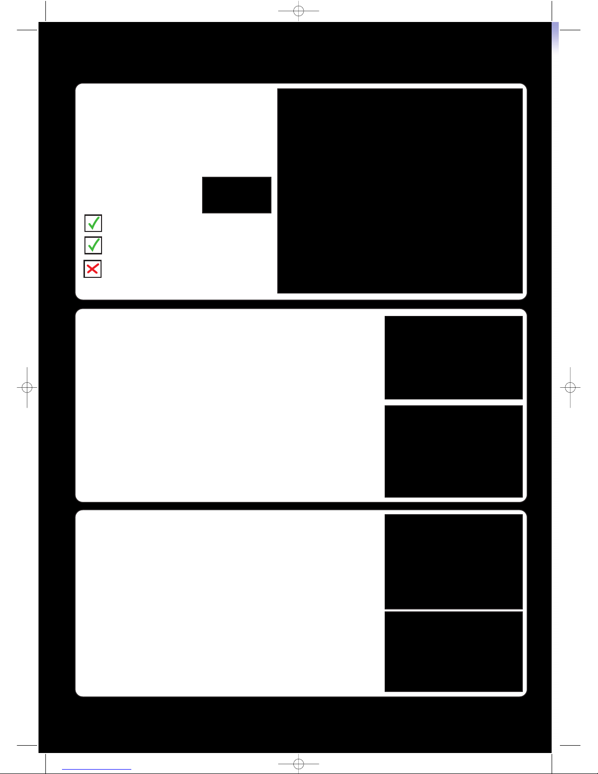
1.UNDERCARRIAGE
1. Apply thread lock to each of
the 25x4mm Cap Screws.
2. Insert 2 Cap screws per leg
and position over the holes in the
fuselage mounting plate.
3. Tighten the Cap Screws using
a 3mm Allan Key.
4. Repeat for the other leg.
PARTS REQUIRED
Fuselage
Main Under Carriage
4off 25x4mm Cap Screws
REQUIRED TOOLS
Thread Lock
3mm Allen Key
1
2
3
4
2. TAIL WHEEL
1. Insert the Aluminum leg into
the Tail Wheel and secure with
thin Cyno.
2. Remove screw and apply Thin
Cyno, tighten up onto the tail
wheel wire.
3. Fit this assembly to the
underside of the fuselage.
4. Secure this with 2 off
2.6 x 8mm Screws
4
3
2
PARTS REQUIRED
Fuselage
Tail Wheel Assembly
2 off 2.6x8mm Screws
REQUIRED TOOLS
Thin Cyno
Pozi Screwdriver
1
TGPF MX2 manual 27/4/11 08:47 Page 5

6
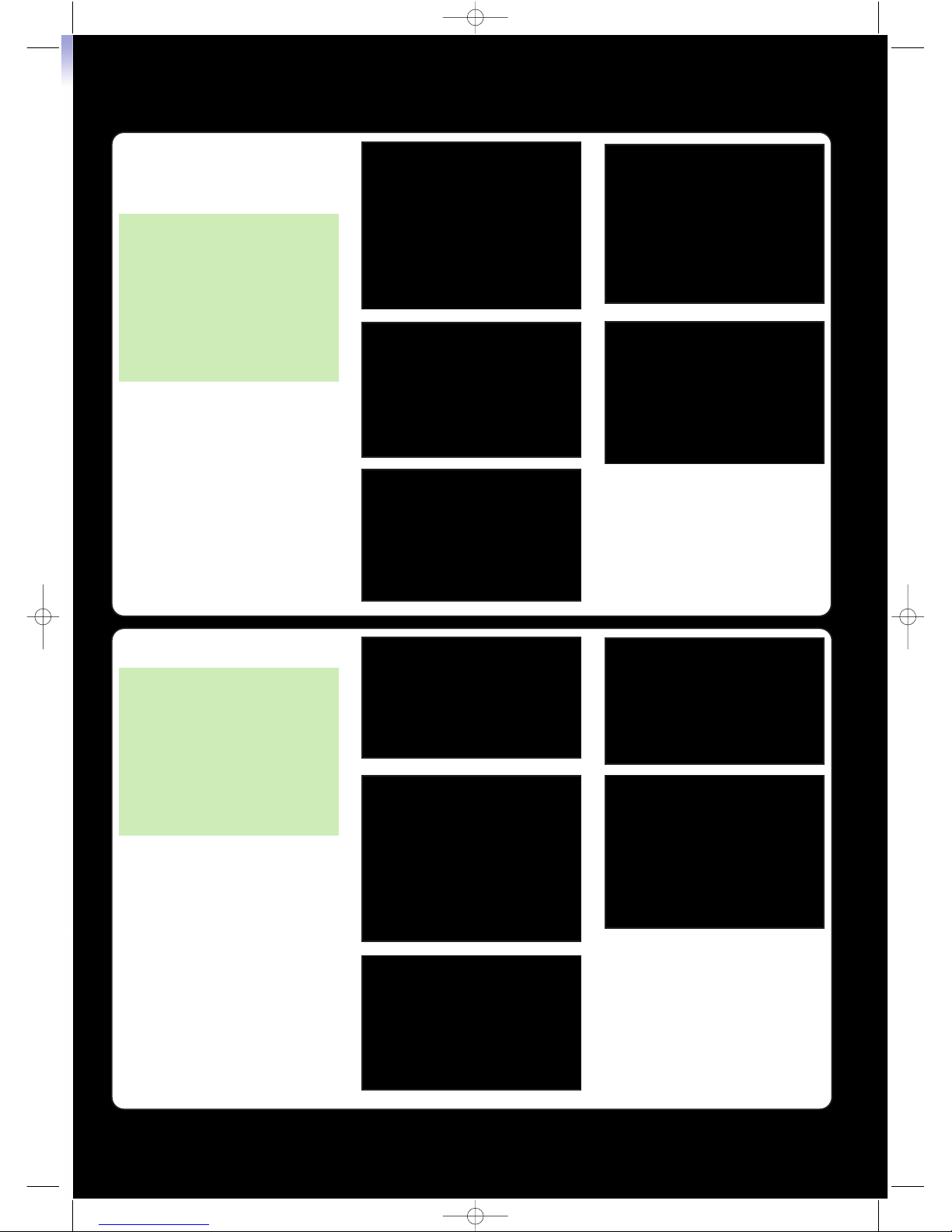
4. RUDDER CONTROL HORNS
1. Fit the Rudder Steering Plate
into the recess of the Vertical
Stab.
2. Fit a Control Horn, secure each
with 2 Screws DIAGONALLY
OPPOSED.
3. Fit the second Control Horn
and secure with 2 Screws fitted
into the free remaining holes.
3. ELEVATOR CONTROL
HORNS
1. Place the control horn on the
underside of the elevator in
the recess.
2. Push through the 4 off
2.6 x 15mm Screws.
3. On the opposite side line up
the screws with the plate and
tighten securely using the Pozi
Screwdriver.
1
2
3
PARTS REQUIRED
Horizontal Tail
Control Horn and Plate
4 off 2.6x15mm Screws
REQUIRED TOOLS
Pozi Screwdriver
PARTS REQUIRED
Vertical Tail
2 off Control Horn
Rudder Steering Plate
4 off 2.6x15mm Screws
REQUIRED TOOLS
Pozi Screwdriver
1
2
3
4
NOTE:
Each Control Horn is only
secured by 2 SCREWS.
The Rudder plate securely
clamps the Rudder and
distributes all loads evenly
from both sides.
TGPF MX2 manual 27/4/11 08:47 Page 6

7
7. CONNECTING UP
ELEVATOR & RUDDER
5. FITTING HORIZONTAL
STAB ASSEMBLY
1. Attach the Stab using the 2 off
45 x 3mm Screws using the
Pozi Screwdriver.
PARTS REQUIRED
Horizontal Tail Assembly
Fuselage
2 off 45x3mm Screws
REQUIRED TOOLS
Pozi Screwdriver
6. FITTING THE VERTICAL
STAB ASSEMBLY
1. Insert the Vertical stab into the
fuselage.
2. Attach the Stab using the 2 off
50 x 3mm Screws.
3. Connect up the springs to the
Rudder Tail Steering Wheel.
2
3
1
PARTS REQUIRED
Vertical Tail Assembly
Fuselage
2 off 50x3mm Screws
2 off Springs
REQUIRED TOOLS
Pozi Screwdriver
PARTS REQUIRED
Fuselage
Required Tools
Pozi Screwdriver
Thread Lock
TGPF MX2 manual 27/4/11 08:47 Page 7

8
3
5
2
1
8. AILERON SET UP
1. Fit Control Horn on the
underside of Aileron in the
recess.
2. Push through 4 off 2.6x15mm
Screws and then screw them
into the top horn plate.
3. Position the Servo Arm so that
it is verical.
4. Chamfer the tip of the ‘Z’ bend
and push this through the outer
most servo arm hole.
5. Ensure the aileron surface is
level and adjust the length of the
Clevis so that it can be
connected.
Repeat for the other wing.
PARTS REQUIRED
Wings
2 off Control Horn and Plates
8 off 2.6x15mm Screws
2 off Pushrods
REQUIRED TOOLS
Pozi Screwdriver
Small File or Dremel with
Sanding Disk
1
CONNECTING UP ELEVATOR
& RUDDER
(continued)
1. Centre the Servo Arms so that
they are parallel to the fuselage
sides.
2. Undo Elevator Quick Connector
3. Connect up the Clevis to the
Elevator, snap lock it in place.
4. Level the Elevator Control
Surface.
5. Apply Thread Lock to the Quick
Connector Screw and tighten up
with a Pozi Screwdriver.
6. By adjusting the Rudder Clevis
length connect the rudder.
4
Ensure the Rudder is positioned
centrally.
7. Check all surfaces move
without binding.
5
TGPF MX2 manual 27/4/11 08:47 Page 8

9
9. FITTING THE WINGS
1. Slide the wing tube into 1
wing.
2. Push this wing and tube into
the hole in the side in of the
fuselage.
3. Feed the Aileron cable through
the squrare hole in the
side of the fuselage.
4. Secure the wing in place using
the 60 x 3mm Screw.
Repeat steps 3 and 4 for the
other Wing
10. CHECKING VERTICAL
AND HORIZONTAL STAB
1. Check the vertical Stab is 90
Degrees to the horizontal Stab
using a Set Square and tape
measure. Adjust if necessary.
2. Check the Horizontal Stab is
level and parallel to wing. Adjust
if necessary.
PARTS REQUIRED
Wing Assemblies
Carbon Wing Tube
2 off 60 x 3mm Screws
Y lead Supplied (We
recommend using - separate
channels)
REQUIRED TOOLS
Pozi Screwdriver
2&3
1
4
PARTS REQUIRED
Airframe assembly
REQUIRED TOOLS
Tape Measure
Set Square
Pozi Screwdriver
Thin Cyno (Optional)
TOP TIP
If you want to maximise performance we
suggest that the horizontal and vertical stab
are glued to the fuselage. Once you have
gone through the above steps apply thin cyno
to the vertical and Horizontal Stabs. Capillary action will draw the
adhesive in, be careful not to overapply as runs can occur.
Y
Y
Y = Y
X
X
X = X
TGPF MX2 manual 27/4/11 08:47 Page 9

10
2
5
3&4
11. PROPELLER AND
SPINNER
1. Remove the nut and washer.
2. Slide on the spinner backplate
onto the shaft.
3. Push on the Propeller and
rotate into its correct position.
4. Fit washer and nut and tighten
with the 10mm Spanner.
5. Attach Spinner and tighten up
the 35x3mm Screw with a Pozi
Screwdrive.
PARTS REQUIRED
Airframe Assembly
3 Blade Propeller
Spinner
1off 35x3mm Screw
REQUIRED TOOLS
Pozi Screwdriver
10mm Spanner
TOP TIP
For Optimum Performance always balance your propellers
12. CANOPY
1. Apply contact adhesive to the
Foam Frame where shown, being
carefull not to go over the edges.
2. Fit into the Fuslage.
3. Fit Clear Canopy to Fuselage
Frame and leave to cure
for at least 30minutes.
4. Remove Canopy Assembly by
lifting from the rear.
PARTS REQUIRED
Canopy frame
Clear Canopy
Airframe Assembly
REQUIRED TOOLS
Contact Adhesive
2
1
3
TGPF MX2 manual 27/4/11 08:47 Page 10

13. COOLING
To Improve the Performance of
the Motor, ESC and Battery we
suggest that you carry out the
following modification to the
airframe.
1. Cut entry hole in ONE side of
the cowl only using a dremel and
sanding drum.
2. Place your template on the
underside of the fuselage and
mark 3 holes at shown
dimensions.
3. Dremel out the marked up
holes, take your time to get a
nice finish
11
1
2
2
3
PARTS REQUIRED
Fuselage Assembly
REQUIRED TOOLS
Dremel with a 20mm Sanding
drum
Pencil
30mm Diameter Template (we
used a red servo horn!)
300mm Rule
14. CENTRE OF GRAVITY
Centre of Gravity for the MX2 is
between 100-110mm measured
from the leading edge of the
wing at the root.
Use the Flight Battery by moving
it fore or Aft to give your
preferred setting.
100-110 mm
C of G
TGPF MX2 manual 27/4/11 08:47 Page 11

12
15. INSTALLING YOUR RADIO (NOT RTF)
1. Please install your radio according to your
manufacturers recommendations on best practice.
2. We recommend that you install each Aileron into
its own seperate channel but we do include a ‘Y’
lead should you choose to use it.
3. Use a small piece of Hook and Loop to retain your
receiver.
4. Confirm that you have set the Radio and Aircraft
correctly by checking stick input and resultant
surface movement.
5. Recommended Control Throws:
Low Rates and Expo
Aileron 30mm Up and Down 20% Expo
Elevator 20mm Up and Down 20% Expo
Rudder 40mm Left and Right 20% Expo
High Rates and Expo
Aileron 30mm Up and Down 30% Expo
Elevator 35mm Up and Down 30% Expo
Rudder 60mm Left and Right 35% Expo
PARTS REQUIRED
2.4Ghz Transmitter (6 Channel Recommended)
2.4Ghz Receiver (6 Channel Recommended)
REQUIRED TOOLS
Hook and Loop
SAFETY:
The ESC default throttle setting (Servo
Direction) is set to NORM for JR and
Spektrum Radio but will need to be set to REV
Direction for Futaba Radio.
IN ALL CASES Always check with the Propeller
removed and be vigillant around a live aircrfaft as
serious injury can occur.
TGPF MX2 manual 27/4/11 08:47 Page 12

13
16. FINAL CHECKS (BEFORE YOU FLY)
Range Test your aircraft, walk 30 metres away from
your aircraft and check that you still have full
control. If you do not, reposition the RX inside the
fuselage and repeat test.
Confirm that your Flight Battery is fully
charged, we recommend that you check
this with a battery checker such as the
Etronix Battery Doctor (Part Number
ET0500).
Confirm that all hardware is fitted securely,
especially control horns, clevices.
Surfaces move in the correct direction.
Transmitter is fully charged, trims and
switches are in the correct place.
FLYING THE MX2
1. You will find that the ground handling of the MX2
is great, especially if you select high rudder rates to
give you maxium movement before you
take off.
2. Gently roll the throttle to about half for a smooth
scale take off.
3. The aircraft will perform the entire aerobatic
catalogue but you will have to mangage your power
and energy.
4. Landing the MX2 on the strip is easy, just line it
up on the runway and bring it in, when you
approach ground effect chop the throttle and
gradually bleed the speed off with the elevator.
Three point landings are best with this type of
aircraft.
5. The Rudder is extremely effective in the air, I
would suggest that if you use your own radio you
dial in a small amount of Expo to help keep things
smooth.
6. To get the best out of this airframe we have
experimented with programmable mixes to
compensate for Rudder to pitch and Rudder to roll
coupling.
7. Have your high Rates on one swich so that you
can instantly switch between them. I always have
my aileron rates set high so that I can initiate
Snap rolls with no switching needed. High rates is
for High Alpaha and Prop Hanging.
We found the following setup virtually eliminates
any coupling:
PMIX 1
To Eliminate PITCH changes when inputting
Rudder.
Master: Rudder
Slave: Elevator
Movements: Right Rudder to give 14% of Up
Elevator
Left Rudder to give 14% of Up
Elevator
PMIX 2
To Eliminate ROLL when inputting the Rudder.
Master: Rudder
Slave: Aileron
Movements: Right Rudder to give 5% of Right
Aileron
Left Rudder to give 5% of Left
Aileron
TGPF MX2 manual 27/4/11 08:47 Page 13

14
RECOMMENDED UPGRADES
1. BATTERY
For outstanding performance and value choose the
new 2200mAh Voltz 14.8v LiPo.
2. CHARGERS
PowerPal 200
The most powerful charger in the range, capable of
delivery upto 200Watts of Power and upto 6 LiPo
Cells.
PowerPal Compact
Simple yet rated to give up to 40Watts, it will charge
a 2200mAh, 14.8v LiPo in an hour.
3. SERVOS
If you want the ulitmate in Speed and Resolution
use Savox Servos, we have had excellent results
with SH-0255-MG
It’s a metal gear servo with 3.9kg of Torque and
class leading resolution and will transform the MX2
flight handling and performance.
Torque 3.9kg
Speed 0.13s
Weight 15.8g
Note: Will require small modification (Plywood rail)
to Elevator and Rudder mounts.
PowerPal 200 Charger
Product code: ET0206
Voltz 2200mah 14.8V
Lipo Cell Pack
PowerPal Compact Charger
Product code: ET0207
Savox SH-0255 Micro Size
Digital Servo
Product code:
SAV-SH0255
TGPF MX2 manual 27/4/11 08:47 Page 14

15
TOP GUN PARKFLITE LIPO CELLS
IMPORTANT SAFETY INSTURCTIONS AND
WARNINGS – READ BEFORE USE
Lithium Polymer batteries can be volatile. Whilst some
of the instances listed below are rare, they can occur
and it is important for you to be aware of how to handle
such situations. Failure to read and follow the below
instructions may result in fire, personal injury and
damage to property if charged or used improperly.
Top Gun Park Flite, its distributers or retailers assume
no liability for failures to comply with these warnings
and safety guidelines.
By using this battery, the buyer assumes all risks
associated with lithium batteries. If you do not agree
with these conditions, return the battery immediately
before use.
The final use and preparation of the battery pack is
ultimately beyond our control and those of our
representatives and retailers. Your decision to use this
product incorporates your agreement that you have read
and understood the safety precautions listed below an
on each battery pack, and that you agree to accept full
responsibility for any injury, loss or damage resulting
from all circumstances surrounding your use or misuse
of this product.
STORAGE AND TRANSPORTATION
1) Store the battery at room temperature between 5 and
26˚C.
2) Do not expose battery pack to direct sunlight (heat)
for extended periods.
3) When transporting or temporarily storing in a vehicle,
temperatures should between –6˚C to 60˚C and ensure
that the battery terminals can’t short.
4) Storing battery temperatures greater than 76˚C for
extended periods (more than 2 hours) may cause
damage to the battery and may lead to a possible fire.
5) Always store the batteries in a fireproof box or LiPo
Bag.
PRODUCT WARRANTY OF BATTERIES
Product warranty is limited to original defects in
material and workmanship. Warranty does not cover
collateral damage. Due to the nature and use of the
battery there is no term warranty. Misuse, abuse,
incorrect charging and other inappropriate use of this
product are not covered under warranty.
GENERAL GUIDELINES AND WARNINGS
FOR LIPO BATTERIES
1. Only use the supplied specific lithium charger. Do not
use a NiMH or NiCd charger – Failure to do so may
cause fire, which may result in personal injury and
property damage.
2. Never charge batteries unattended. When charging
LiPo batteries you should always remain in constant
observation to monitor the charging process and react
to potential problems that may occur.
3. If at any time you witness a battery starting to
balloon or swell up, discontinue the charging process
immediately, disconnect the battery and observe it in a
safe place for approximately 15 minutes. The battery
electrolyte may leak, and the reaction with the air may
cause the chemicals to ignite, resulting in a fire.
4. Since delayed chemical reaction can occur, it is best
to observe it in a safe place for approximately 15
minutes should any damage occur to your battery.
5. Additionally, if a short occurs and contact is made
with metal (such as rings on your hand), severe injuries
may occur due to the conductibility of electric current.
6. Do not bend, crush, drill or cut open your battery.
In the event of a crash, you must remove the battery for
observation and in a place where it is away from
combustible material for approximately 15 minutes.
7. Never store or charge the battery pack inside your
car in extreme temperatures, since extreme
temperatures it could ignite. Do not expose the battery
to fire or any temperatures exceeding 76˚C.
8. After use please let the battery cool to ambient
temperature before charging.
9. Do not over-discharge the battery. Discharging the
battery below 3 volts per cell may cause damage to the
pack resulting in reduced performance and duration.
When a drop in power occurs in flight land immediately
to avoid discharging the batteries below 3 Volts per cell.
10. Should you get the electrolyte on your skin wash it
off immediately with soap and water. Should you get the
electrolyte in your eyes flush generously with water for
10 minutes and seek medical attention.
11. 3.7 Volts is the average voltage of each cell; a LiPo
can be charged up to 4.2 Volts and discharged to 3
Volts, any higher or lower in voltage and the cell will
almost certainly be damaged and may become unstable.
This can be very dangerous as there is a fire risk.
12. If disposing of a LiPo battery proceed as follows:
Submerse the battery into a container filled with about
10 litres of salt water (one cup of salt in 10L).
Leave the battery submerged for 2 weeks, this will
slowly and safely discharge the battery until the voltage
has dropped to zero volts which eliminates the risk of
any chemical reaction. It can then be disposed off in the
general waste collection.
TGPF MX2 manual 27/4/11 08:47 Page 15

TGP0335B MX2 Green Fuselage
TGP0335G MX2 Blue Fuselage
TGP0336B MX2 Green main wing
TGP0336G MX2 Blue main wing
TGP0337B MX2 Green Horizontal tail
TGP0337G MX2 Blue Horizontal tail
TGP0338B MX2 Green vertical tail
TGP0338G MX2 Blue vertical tail
TGP0339 MX2 Canopy
TGP0340B MX2 Green cowling
TGP0340G MX2 Blue cowling
TGP0341B MX2 Green cover
TGP0341G MX2 Blue cover
TGP0342 MX2 pilot (option)
TGP0343 MX2 Spinner
TGP0344 Propeller
TGP0345 PU wheel
TGP0346 Fuselage plastic parts
TGP0347 Wing plastic parts
TGP0348 Vertical tail plastic parts
TGP0349 Screw parts
TGP0539 MX2 650KV motor
TGP0350 Motor struct
TGP0351 Metal wire of landing gear
TGP0352 Wing carbon spar
TGP0353 Aluminium Prop Adaptor
TOP GUN PARK FLITE MX2 SPARE PARTS LIST
DISTRIBUTORS OF QUALITY MODEL & HOBBY PRODUCTS
Saxon House, Saxon Business Park, Hanbury Road, Bromsgrove, Worcestershire. B60 4AD. England
Tel: +44 (0) 1527 575349 Fax: + 44 (0) 1527 570536
E-mail: info@cmldistribution.co.uk
Web site: www.cmldistribution.co.uk
TGPF MX2 manual 27/4/11 08:47 Page 16
 Loading...