

)
XC6901 Series
200mA Negative Voltage Regulator with ON/OFF Control
■GENERAL DESCRIPTION
The XC6901 Series is a negative voltage CMOS regulator which includes a reference voltage source, error amplifier, driver
transistor, current limiter and phase compensator.
The CE function enables the circuit to be in stand-by mode by inputting low level signal. In the stand-by mode, the electric
charge at the output capacitor (C
quickly returns to the V
The over current protection circuit will operate when the output current reaches limit current. The thermal shutdown circuit will
operate when the junction temperature reaches limit temperature.
■APPLICATIONS
●CCD power supplies
●LCD Modules
●Op-Amp power supplies
●Digital still cameras
●Battery powered equipment
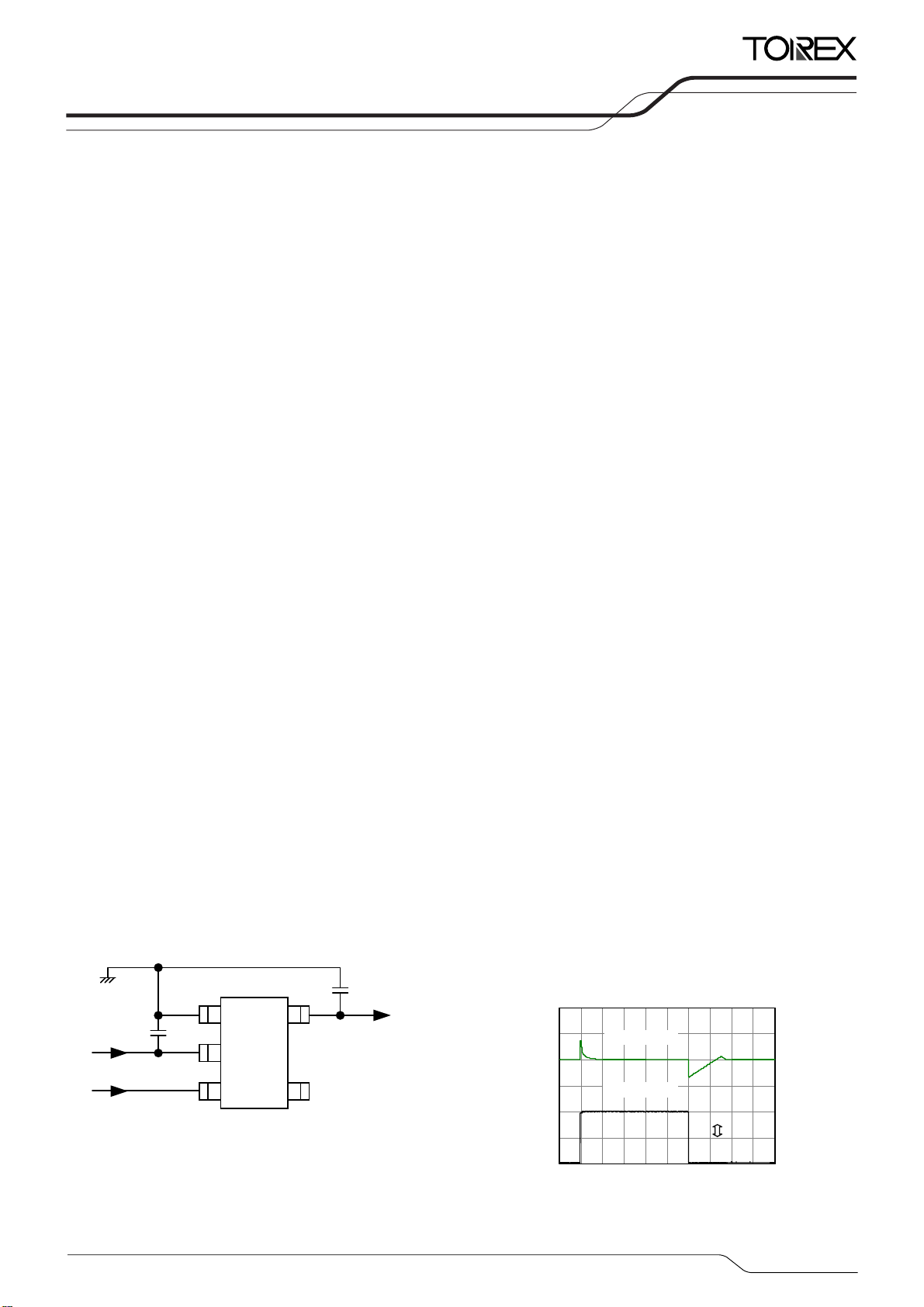
■TYPICAL APPLICATION CIRCUIT
:1.
C
IN
ceramic
(
-V
IN
CE
GND
0
μF
)
level.
SS
SOT -25
TOP VIEW
(
) will be discharged via the internal auto-discharge switch and as a result the -V
L
■FEATURES
Maximum Output Current
Input Voltage Range
Output Voltage Range
Accuracy
Temperature Stability
CE High Level Voltage
Dropout Voltage
Low Power Consumption
Stand-by Current
Protection Circuits
Output Capacitor
Built-in Function
Operating Ambient Tempera ture
Packages
Environmentally Friendly
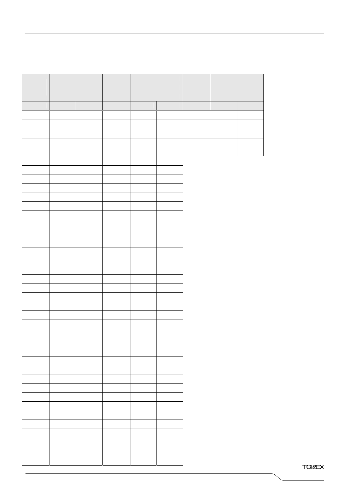
■ TYPICAL PERFORMANCE
CHARACTERISTICS
1.0
CL:
μF
ceramic
)
(
-V
OUT
NC
)
: 200mA
: -2.4V ~-12.4V(V
:
-0.9V~-12.0V
: ±1.5%(V
±0.03V(V
:
TYP. ±50ppm/℃
:
+1.2V~+3.6V,(Active High)
: 400mV@I
: 100μA MAX.
: Less than 0.1μA
:
Current Limit 350mA TYP, Foldback
Overheat Protection T
:
Ceramic Capacitor Compatible
:
CL High-Speed Discharge
: -40℃~+85℃
: SOT-25, SOT-89-5, USP-6C
: EU RoHS Compliant, Pb Free
XC6901x501
I
=1⇔100mA,tr=tf=5μs,Ta=25℃,VCE=1.5V
OUT
V
=-6V,CIN=1μF(ceram ic),CL=1μF(ceramic
-4.6
[V]
-4.8
OUT
-5.0
-5.2
-5.4
Output Voltage: V
-5.6
-5.8
IN
Output Voltage
Output Current
1mA
100mA
Time(100μs/div)
<‐2.0V)
OUT
OUT
OUT
OUT
≧‐2.0V)
=100mA
ETR03043-006
pin
=3.6V)
CE
=150℃
TSB
300
250
[mA]
OUT
200
150
100
Output Current: I
50
0
1/28

XC6901
Series
■PIN CONFIGURATION
* The dissipation pad for the USP-6C package should be solder-plated in recommended mount pattern and metal masking to enhance
mounting strength and heat release. If the pad needs to be connected to other pins, it should be connected to the -V
■PIN ASSIGNMENT
PIN NUMBER
USP-6C SOT-25 SOT-89-5
1 5 5 -V
2,5 4 1 NC No Connection
3 2 2 -VIN Negative Supply Input
4 3 3 CE ON/OFF Control
6 1 4 GND Ground
PIN NAME FUNCTIONS
Negative Output
OUT
(No. 3) pin.
IN
■FUNCTION CHART
XC6901 Series D type
PIN NAME SIGNAL STATUS
L Stand-by
CE
H Active
OPEN Stand-by
2/28
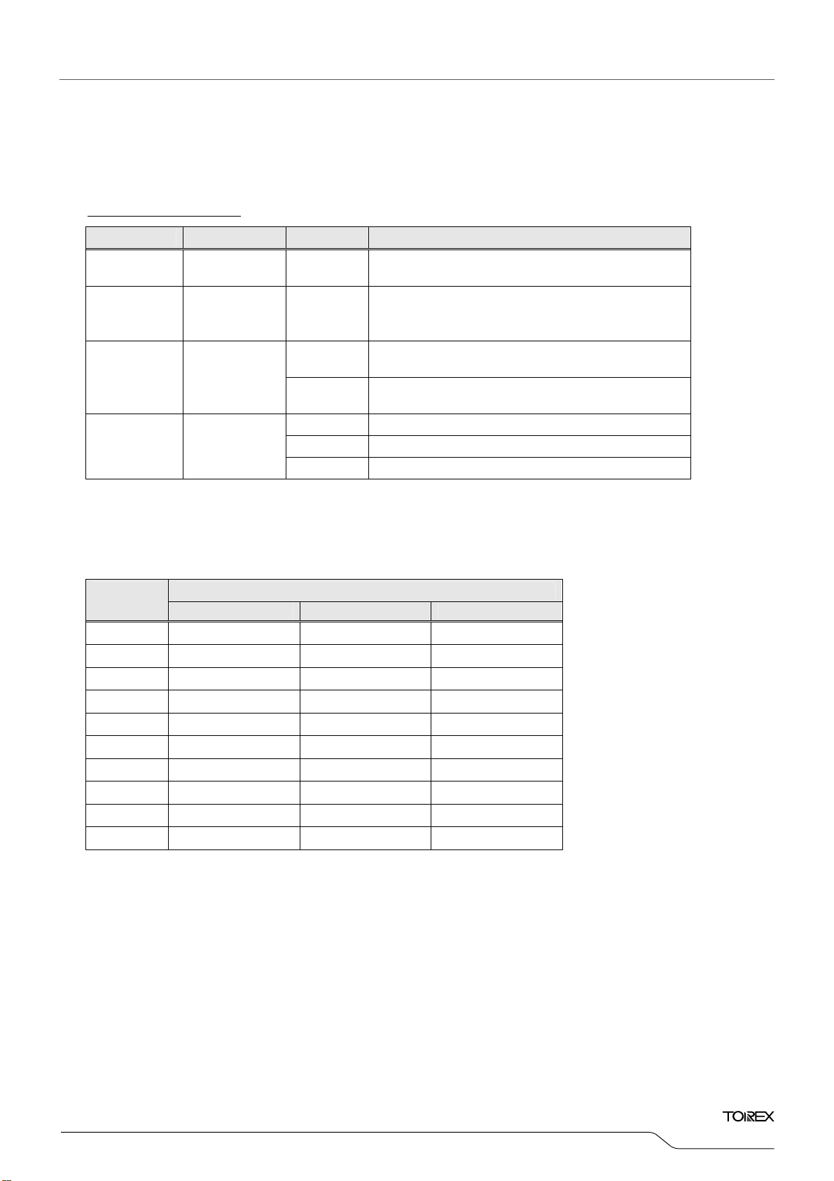
■PRODUCT CLASSIFICATION
●Ordering Information
XC6901①②③④⑤⑥-⑦
DESIGNATOR ITEM SYMBOL DESCRIPTION
①
②③
④ Output Type
⑤⑥-⑦
(*1)
The “-G” suffix denotes Halogen and Antimony free as well as being fully RoHS compliant.
(*2)
For the type without CL auto-discharge, please contact your local Torex sales office or representative.
Output Voltage
(*1)
(*2)
Type
Packages
(Order Unit)
ON/OFF Control Voltage Regulator (CE Active High)
D
09~C0
1
B
ER-G USP-6C(3,000/Reel)
MR-G SOT-25(3,000/Reel)
PR-G SOT-89-5 (1,000/Reel)
CE Pull-down resistor
CL Auto-discharge
-0.9V~-12V
e.g. -0.9V→②=0, ③=9, -12V→②=C, ③=0
A:10, B:11, C:12
0.10V Increments
e.g. -1.2V→②=1, ③=2, ④=1
0.05V Increments for -0.95V~-4.95V
e.g. -1.25V→②=1, ③=2, ④=B
XC6901
Series
■STANDARD VOLTAGE
●Examples for standard voltage
OUT
(V)
-1.2V XC6901D121ER-G XC6901D121MR-G XC6901D121PR-G
-2.5V XC6901D251ER-G XC6901D251MR-G XC6901D251PR-G
-2.6V XC6901D261ER-G XC6901D261MR-G XC6901D261PR-G
-3.0V XC6901D301ER-G XC6901D301MR-G XC6901D301PR-G
-3.3V XC6901D331ER-G XC6901D331MR-G XC6901D331PR-G
-4.0V XC6901D401ER-G XC6901D401MR-G XC6901D401PR-G
-4.5V XC6901D451ER-G XC6901D451MR-G XC6901D451PR-G
-5.0V XC6901D501ER-G XC6901D501MR-G XC6901D501PR-G
-6.0V XC6901D601ER-G XC6901D601MR-G XC6901D601PR-G
-12.0V XC6901DC01ER-G XC6901DC01MR-G XC6901DC01PR-G
USP-6C SOT-25 SOT-89-5
PACKAGES V
3/28
XC6901
Series
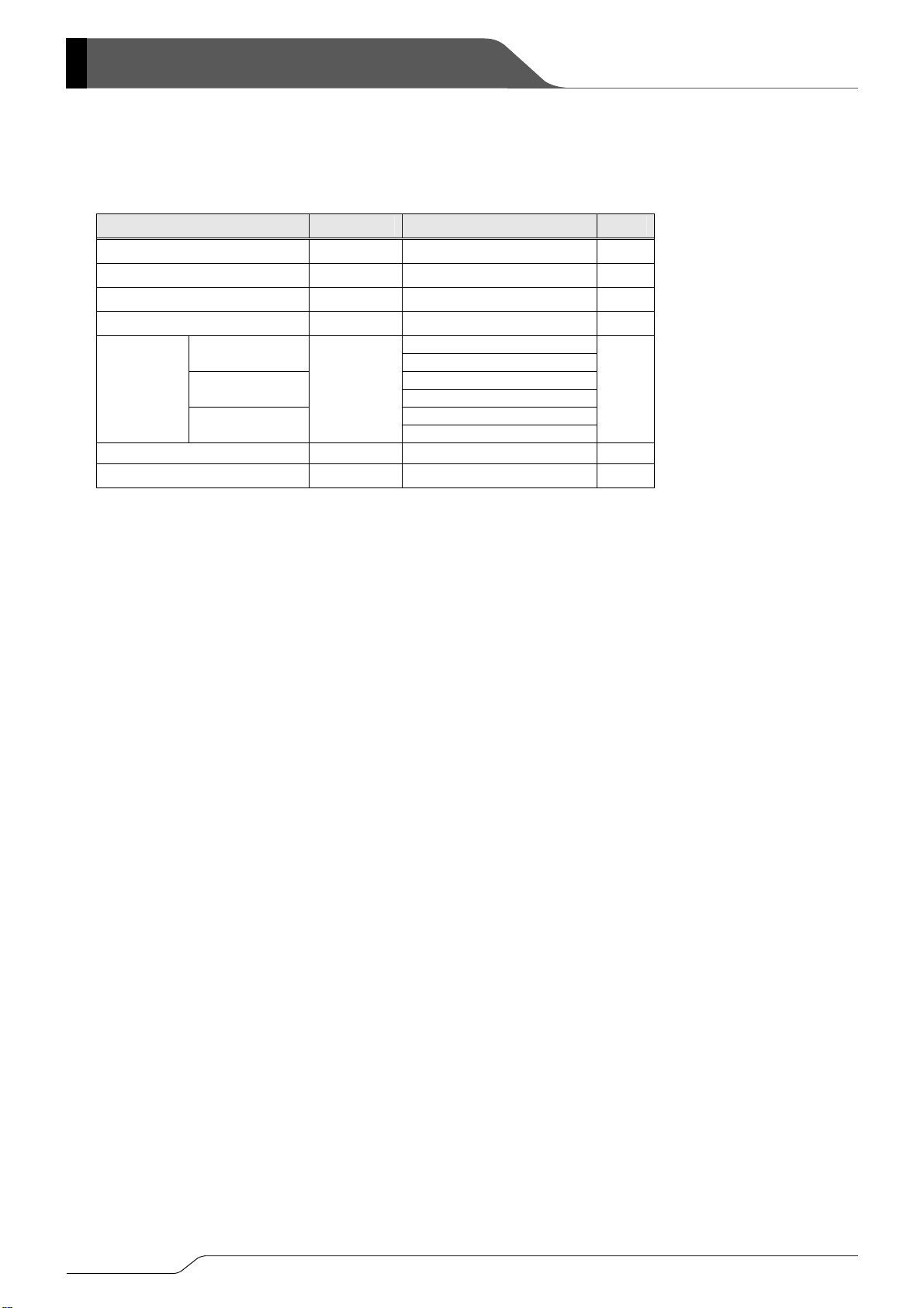
■ABSOLUTE MAXIMUM RATINGS
PARAMETER SYMBOL RATINGS UNITS
Input Voltage VIN GND-18+VCE ~ GND+0.3 V
Output Current I
Output Voltage V
CE Input Voltage VCE GND-0.3 ~ VIN+18 V
USP-6C
Power
Dissipation
Operating Ambient Temperature
Storage Temperature Tstg -55~+125 ℃
(*1): Please use within the range of I
(*2) The power dissipation figure shown is PCB mounted and is for reference only. Please refer to page 24~26 for details.
SOT-25
SOT-89-5
≦Pd/( V
OUT
500
OUT
-VIN-0.3 ~ GND+0.3 V
OUT
120
1000 (PCB mounted)
Pd
Topr -40~+85 ℃
- VIN)
OUT
600 (PCB mounted)
1300 (PCB mounted)
250
500
GND=0V, Ta=25℃
(*1)
mA
(*2)
(*2)
(*2)
mW
4/28
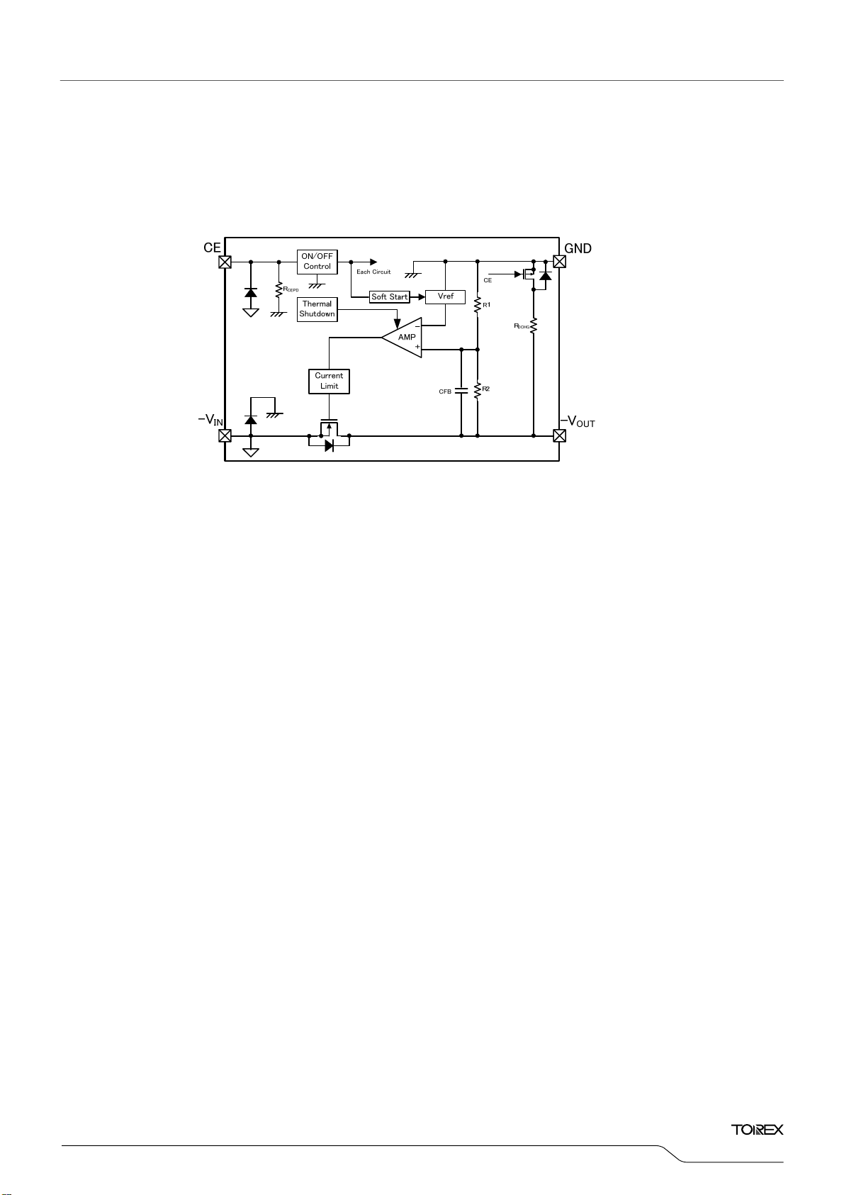
■BLOCK DIAGRAM
XC6901 Series D type
*Diodes inside the circuit are an ESD protection diode and a parasitic diode.
XC6901
Series
5/28

XC6901
Series
■ELECTRICAL CHARACTERISTICS
●XC6901 Series
GND=0V,Ta=25℃
PARAMETER SYMBOL CONDITIONS MIN. TYP. MAX. UNITS CIRCUIT
V
<-2.0V
Output Voltage V
Maximum Output
(*4)
Current
OUT(E)
I
OUTMAX
Load Regulation ΔV
Dropout Voltage Vdif
Supply Current I
Stand-by Current I
Input Line
Regulation
ΔV
(ΔV
(*2)
I
OUT
(*3)
I
V
BIAS
V
STB
/
OUT
・
V
)
IN
OUT
=20mA
OUT
VIN=V
-2.0V
OUT(T)
VIN=-4.4V
VIN=V
-1.0V
OUT(T)
VIN=-4.0V
1mA≦I
OUT
=20mA - E-1
OUT
=-14.5V, VCE=1.5V, I
IN
=-14.5V, VCE=0V, I
IN
-14.5V~V
OUT(T)
-14.5V~-2.4V
I
=20mA
OUT
V
V
V
V
V
≦100mA
-1V
V
V
OUT(T)
≧-2.0V
OUT(T)
≦-2.4V
OUT(T)
>-2.4V
OUT(T)
≦-3.0V
OUT(T)
>-3.0V
OUT(T)
=0mA - 100 200
OUT
=0mA - 0.01 0.1
OUT
≦-1.4V
OUT(T)
>-1.4V
OUT(T)
Input Voltage VIN -16+V
Output Voltage
Temperature
Characteristics
Power Supply
Rejection Ratio
Limit Current I
ΔV
(ΔTopr
PSRR
LIM
OUT
・
/
I
=20mA
OUT
V
-40℃≦Topr≦85℃
)
OUT
V
IN
={ V
-1.0} +0.5Vp-pAC, I
OUT(T)
=20mA,
OUT
f=1kHz
VIN=V
-2.0V
OUT(T)
VIN=-4.4V
V
V
OUT(T)
OUT(T)
≦-2.4V
>-2.4V
×1.015 ×0.985
-0.030
V
OUT(T)
(*1)
+0.030
V
200 - - mA
- 20 60 mV
(*5)
mV
μA ①
μA ①
- 0.01 0.20 %/V
- -2.4 V ①
CE
- ±50 -
- 45 -
ppm/℃①
dB ②
210 300 - mA
①
①
①
①
①
①
Short-Circuit Current I
VIN=V
SHORT
-2.0V Short -V
OUT(T)
to GND level - 80 - mA ①
OUT
Detect Thermal
T
Shutdown
IC Junction temperature - 150 -
TSD
Temperature
Release Thermal
T
Shutdown
IC Junction temperature - 125 -
TSR
Temperature
Hysteresis Width T
CE "H" Level Voltage
CE "L" Level Voltage
CE "H" Level
Current
CE "L" Level Current
CL Discharge
Resistor
Soft Start Time tSS
NOTE: Unless otherwise stated regarding input voltage conditions VCE=1.5V、GND=0V、VIN=V
T
HYS
V
1.2 - 3.6 V
CEH
V
GND - 0.4 V
CEL
V
I
R
CEH
I
CEL
DCHG
V
V
VIN=-8V,V
R
CE="H" to
95% of V
- 25 -
TSD-TTSR
=-12.4V,
IN
=3.6V
CE
=GND -0.1 - 0.1
CE
=3kΩ,Rise Time
L
XC6901D Series 1.8 4 7
=-2V,VCE=GND 0.7 1.2 1.8 kΩ
OUT
0.15 0.4 1.2 ms
0.3 0.7 2 ms
-1.0V or -2.4V the one which bigger
OUT(T)
OUT(E)
V
>-4.0V
OUT(T)
V
≦-4.0V
OUT(T)
absolute value.
*1) V
*2) V
(ie. The output voltage when “V
*3)Vdif=-{V
V
: Nominal output voltage
OUT(T)
: Effective output voltage (see the voltage chart)
OUT(E)
- V
OUT1
}
IN1
is the input voltage when V
IN1
V
is the voltage equal to 98% of the normal output voltage when amply stabilized V
OUT1
the V
pin.
IN
-1.0V” or “-2.4V”is provided at the VIN pin while maintaining a certain I
OUT(T)
appears at the V
OUT1
pin while input voltage is gradually increased
OUT
value.
OUT
-1.0V or -2.4V (the bigger absolute value one ) are input at
OUT (T)
*4) The maximum current may not be able to flow when thermal shutdown operates, it depends on power dissipation.
*5) E-1: Refer to dropout voltage chart.
℃ ①
℃ ①
℃ ①
①
①
μA ①
μA ①
①
③
③
6/28
■ELECTRICAL CHARACTERISTICS(Continued)
Dropout Voltage Chart (V
NOMINAL
OUTPUT
VOLTAGE
V
OUT(T)
-0.90 800 1500 -2.85 116 157 -4.80 80 115
-0.95 750 1450 -2.90 114 155 -4.85 80 115
-1.00 700 1400 -2.95 112 153 -4.90 79 115
-1.05 650 1350 -3.00 110 151 -4.95 79 115
-1.10 600 1300 -3.05 109 150 -5.00 78 114
-1.15 550 1250 -3.10 108 148
-1.20 500 1200 -3.15 107 147
-1.25 450 1150 -3.20 105 145
-1.30 400 1100 -3.25 104 144
-1.35 350 1050 -3.30 102 142
-1.40 300 1000 -3.35 102 141
-1.45 270 950 -3.40 101 140
-1.50 230 900 -3.45 101 139
-1.55 220 850 -3.50 100 137
-1.60 210 800 -3.55 99 136
-1.65 205 750 -3.60 98 135
-1.70 200 700 -3.65 97 134
-1.75 195 650 -3.70 95 133
-1.80 190 600 -3.75 95 132
-1.85 183 550 -3.80 94 131
-1.90 176 500 -3.85 94 130
-1.95 171 450 -3.90 93 129
-2.00 165 400 -3.95 92 128
-2.05 161 350 -4.00 91 127
-2.10 156 300 -4.05 90 126
-2.15 152 250 -4.10 89 125
-2.20 148 200 -4.15 89 125
-2.25 144 187 -4.20 88 124
-2.30 140 185 -4.25 87 123
-2.35 138 183 -4.30 86 122
-2.40 135 181 -4.35 86 122
-2.45 132 178 -4.40 85 121
-2.50 129 174 -4.45 85 120
-2.55 127 172 -4.50 84 119
-2.60 125 169 -4.55 83 119
-2.65 123 166 -4.60 82 119
-2.70 121 163 -4.65 82 118
-2.75 119 161 -4.70 82 117
-2.80 117 159 -4.75 81 116
DROPOUT VOLTAGE DROPOUT VOLTAGE DROPOUT VOLTAGE
Vdif (mV)
TYP. MAX. V
=-0.9V~-5V)
OUT(T)
E-1 E-1 E-1
NOMINAL
OUTPUT
VOLTAGE
TYP. MAX. V
OUT(T)
Vdif (mV)
NOMINAL
OUTPUT
VOLTAGE
TYP. MAX.
OUT(T)
Vdif (mV)
XC6901
Series
7/28

XC6901
Series
■ELECTRICAL CHARACTERISTICS(Continued)
Dropout Voltage Chart (V
NOMINAL
OUTPUT
VOLTAGE
V
OUT(T)
-5.1 77 113 -9.0 58 93
-5.2 77 112 -9.1 58 92
-5.3 76 111 -9.2 58 92
-5.4 75 110 -9.3 57 92
-5.5 74 110 -9.4 57 91
-5.6 73 109 -9.5 56 91
-5.7 73 108 -9.6 56 91
-5.8 72 107 -9.7 56 91
-5.9 71 106 -9.8 55 90
-6.0 70 105 -9.9 55 90
-6.1 70 105 -10.0 54 90
-6.2 69 104 -10.1 54 90
-6.3 69 104 -10.2 54 89
-6.4 68 103 -10.3 54 89
-6.5 67 102 -10.4 54 89
-6.6 66 102 -10.5 53 88
-6.7 66 101 -10.6 53 88
-6.8 65 101 -10.7 53 88
-6.9 65 100 -10.8 53 88
-7.0 65 100 -10.9 53 88
-7.1 64 99 -11.0 52 88
-7.2 64 99 -11.1 53 88
-7.3 63 98 -11.2 52 87
-7.4 63 98 -11.3 51 87
-7.5 62 98 -11.4 51 87
-7.6 62 98 -11.5 50 87
-7.7 62 97 -11.6 50 87
-7.8 61 96 -11.7 50 87
-7.9 61 96 -11.8 50 87
-8.0 60 96 -11.9 50 87
-8.1 60 96 -12.0 50 87
-8.2 60 95
-8.3 60 95
-8.4 60 94
-8.5 59 94
-8.6 59 94
-8.7 59 94
-8.8 59 93
-8.9 59 93
DROPOUT VOLTAGE DROPOUT VOLTAGE
Vdif(mV)
TYP. MAX. V
=-5.1V~-12V)
OUT(T)
E-1 E-1
NOMINAL
OUTPUT
VOLTAGE
TYP. MAX.
OUT(T)
Vdif(mV)
8/28

■TEST CIRCUITS
1) CIRCUIT①
2) CIRCUIT②
3) CIRCUIT③
V
CE
SW1
-V
IN
V
CIN=1μF(ceramic)
A
XC6901
Series
A
CE
V
GND
-V
C
L=1μF
(ceramic)
I
OUT
V
OUT1
V
A
-V
OUT
IN
SW2
9/28

XC6901
Series
■OPERATIONAL EXPLANATION
The voltage divided by resisters R1 and R2 is compared with the internal reference voltage based on ground by the
error amplifier. The driver transistor tied to the –V
voltage at the –V
pin is controlled and stabilized by a system of negative feedback.
OUT
<Soft Start Function>
XC6901 Series includes soft-start circuit. During power start-up, the inrush current from -V
charge CL capacitor can be reduced and it makes the VIN stable. Soft-start time (tSS) is optimized internally.
pin is then driven by the subsequent output signal. The output
IN
pin to V
IN
OUT
pin to
Figure1:Soft Start Time and Inrush Current
<Current Limit, Short-Circuit Protection>
The XC6901 series’ fold-back circuit operates as an output current limiter and a short protection circuit for the output pin. When the
output current reaches the current limit level, output voltage drops with the decrease of the output current. There are no parasitic diode
between the –V
pin and GND pin. The minimized short-circuit current is maintained even if the –V
OUT
pin voltage is pulled up toward
OUT
positive.
<Thermal Shutdown>
The XC6901 Series has an internal thermal Shutdown(TSD) circuit for protection against overheating.
When the junction temperature reaches the detection temperature, the driver transistor is forcibly turned off. When the junction
temperature falls to the release temperature with the driver transistor still in the off state, the driver transistor turns on (automatic
recovery) and restarts regulator operation.
<CE Pin>
The XC6901 Series is able to shut down the regulator circuit using the CE pin signal. CE pin can be controlled with positive voltage due
to P-channel transistor source input (Gate is grounded). A current flow of a few micro amperes. The regulator is turned on when CE input
voltage is positive, the regulator is turned off when CE input is GND.
When CE pin is open, IC is turned OFF, due to the built-in Pull-down resistor. When the IC is turned OFF with low input voltage to the
CE pin,-V
pin voltage goes into GND level by R1,R2 and CL discharge resistance(R
OUT
DCHG
).
10/28

XC6901
Series
■OPERATIONAL EXPLANATION(Continued)
<CL High Speed Discharge>
The XC6901D type is capable of high-speed discharge of the charge that collects on the output capacitor (C
accomplished by the P-channel MOSFET and C
discharge resistance connected between the -V
L
and GND pins in the block
OUT
diagram, and takes place when the L-level signal (IC internal circuit shutdown signal) of the CE pin is input so that it could avoids
malfunction.
The C
resistance R
the CR discharge equation below. Please be noted that R
discharge time is determined by this CL discharge resistance and CL. Letting the time constant of the CL discharge
L
and CL be τ (τ = C × R), the output voltage after discharge by the P-channel MOSFET can be obtained from
DCHG
various with supply voltage and VDS(drain-source voltage) since it
DCHG
consists of P-channel MOSFET.
t = τln(V
OUT(E)
/ V)
V:Output voltage during discharge
V
:Output voltage
OUT(E)
t:Discharge time
auto-discharge resistance R
τ:C
L
× CL Output capacitor value CL
DCHG
<Low ESR Capacitor>
With the XC6901 series, a stable output voltage is achievable even if used with low ESR capacitors, as a phase compensation
circuit is built-in. The output capacitor (C
) should be connected as close to -V
L
pin and GND pin to obtain stable phase
OUT
compensation. Values required for the phase compensation are as the table below.
For a stable power input, please connect an input capacitor (C
compensation while avoiding run-out of values, please use the capacitor (C
temperature too much. The table below shows recommended values of C
) near power supply. In order to ensure the stable phase
IN
, CL) which does not depend on bias or
IN
, CL for all environment conditions.
IN
below). This is
L
CHART 1:Recommended Values of C
OUTPUT VOLTAGE RANGE INPUT CAPACITOR OUTPUT CAPACITOR
V
CIN CL
OUT(T)
-0.9V~-12V 1.0μF~ 1.0μF~100μF
IN, CL
(MIN.)
11/28

XC6901
Series
■NOTE ON USE
1) For temporary, transitional voltage drop or voltage rising phenomenon.
The IC is liable to malfunction should the ratings be exceeded.
2) Where wiring impedance is high, operations may become unstable due to noise and/or phase lag depending on output
current. Please enforce wiring –V
3) Please wire the C
and CL as close to the IC as possible.
IN
4) Capacitances of these capacitors (C
Care shall be taken for capacitor selection to ensure stability of phase compensation from the point of ESR influence.
5) Torex places an importance on improving our products and its reliability. However, by any possibility, we would
request user fail-safe design and post-aging treatment on system or equipment.
and GND.
IN
, CL) are decreased by the influences of bias voltage and ambient temperature.
IN
12/28

)
)
)
)
)
)
■TYPICAL PERFORMANCE CHARACTERISTICS
(1) Output Voltage vs. Output Current
XC6901
Series
XC6901x331
C
= 1 .0μ F (cera mi c), C
0.0
-0.5
[V]
OUT
-1.0
-1.5
-2.0
-2.5
-3.0
Output Voltage: V
-3.5
-4.0
0 50 100 150 200 250 300 350 400 450
Output Current: I
XC6901x501
C
= 1. 0μF (cer ami c), CL = 1 .0μF (cera mi c
IN
0.0
-1.0
[V]
OUT
-2.0
V
= -5.3V,VCE=1.5V
IN
= 1. 0μF (cer ami c
[mA]
OUT
V
IN
Ta=-40℃
Ta=25℃
Ta=85℃
= -7 .0V, VCE=1.5V
Ta=-40℃
Ta=25℃
Ta=85℃
0.0
-0.5
[V]
-1.0
OUT
-1.5
-2.0
-2.5
-3.0
Output Voltage: V
-3.5
-4.0
0 50 100 150 200 250 300 350 400 450
0.0
-1.0
[V]
OUT
-2.0
XC6901x331
C
= 1. 0μF (cer ami c), CL = 1.0μF (ceram ic
IN
Output Current: I
OUT
[mA]
XC6901x501
C
= 1. 0μF (cer ami c), CL = 1.0μF (ceram ic
IN
Ta=25℃,V
VIN=-4.3V
VIN=-5.3V
VIN=-6.3V
Ta=25℃,V
VIN=-6V
VIN=-7V
VIN=-8V
=1.5V
CE
=1.5V
CE
-3.0
-4.0
Output Voltage: V
-5.0
-6.0
0 50 100 150 200 250 300 350 400 450
Output Current: I
OUT
[mA]
XC6901xC01
V
= -14V,VCE=1.5V
OUT
IN
Ta=-40℃
Ta=25℃
Ta=85℃
[mA]
C
= 1 .0μ F (cera mi c), CL = 1 .0μF (cera mi c
IN
0.0
-2.0
[V]
-4.0
OUT
-6.0
-8.0
-10.0
Output Voltage: V
-12.0
-14.0
0 50 100 150 200 250 300 350 400 450
Output Current: I
-3.0
-4.0
Output Voltage: V
-5.0
-6.0
0 50 100 150 200 250 300 350 400 450
Output Current: I
OUT
[mA]
XC6901xC01
Ta=25℃,V
=1.5V
C
= 1. 0μF (cer ami c), CL = 1.0μF (cera mic
IN
0.0
-2.0
[V]
-4.0
OUT
-6.0
-8.0
-10.0
Output Voltage: V
-12.0
-14.0
0 50 100 150 200 250 300 350 400 450
Output Current: I
OUT
CE
VIN=-14V
VIN=-14.5V
[mA]
13/28

)
V
)
)
V
)
)
)
XC6901
Series
■TYPICAL PERFORMANCE CHARACTERISTICS (Continued)
(2) Output Voltage vs. Input Voltage
XC6901x331
I
=20mA,VCE=1.5V
= 1. 0μF (ce rami c), CL = 1.0μF (cera mic
C
IN
0.0
-0.5
[V]
-1.0
OUT
-1.5
-2.0
-2.5
-3.0
Output Voltage: V
-3.5
-4.0
Input Voltage: V
OUT
0.0
Ta=-40℃
Ta=25℃
Ta=85℃
-0.5
[V]
-1.0
OUT
-1.5
-2.0
-2.5
-3.0
Output Voltage: V
-3.5
-4.0
-15.0-12.0-9.0-6.0-3.00.0
[V]
IN
XC6901x331
= 1. 0μF (ce rami c), CL = 1.0μF (ceramic
C
IN
Input Voltage: V
[V]
IN
Ta=25℃,V
IOUT=1mA
IOUT=20mA
IOUT=50mA
CE
=1.5V
-15.0-12.0-9.0-6.0-3.00.0
[V]
OUT
Output Voltage: V
[V]
OUT
Output Voltage: V
0.0
-1.0
-2.0
-3.0
-4.0
-5.0
-6.0
0.0
-2.0
-4.0
-6.0
-8.0
-10.0
-12.0
-14.0
XC6901x501
CIN = 1. 0μF (ce rami c), CL = 1.0μF (cera mic
Input Voltage: V
XC6901xC01
= 1. 0μF (ce rami c), CL = 1.0μF (cera mic
C
IN
Input Voltage: V
IN
IN
I
[V]
I
[V]
OUT
OUT
Ta=-40℃
Ta=25℃
Ta=85℃
=20mA,VCE=1.5
Ta=-40℃
Ta=25℃
Ta=85℃
=20mA,VCE=1.5V
XC6901x501
= 1. 0μF (ce rami c), CL = 1.0μF (cera mic
C
IN
Ta=25℃, V
CE
=1.5V
0.0
-1.0
[V]
-2.0
OUT
IOUT=1mA
IOUT=20mA
IOUT=100mA
-3.0
-4.0
-5.0
Output Voltage: V
-6.0
-15.0-12.0-9.0-6.0-3.00.0
Input Voltage: V
XC6901xC01
CIN = 1. 0μF (ce rami c), CL = 1.0μF (cera mic
IN
[V]
Ta=25℃, V
-15.0-12.0-9.0-6.0-3.00.0
=1.5
CE
0.0
-2.0
[V]
-4.0
OUT
IOUT=1mA
IOUT=20mA
IOUT=100mA
-6.0
-8.0
-10.0
Output Voltage: V
-12.0
-14.0
-15.0-12.0-9.0-6.0-3.00.0
Input Voltage: V
[V]
IN
-15.0-12.0-9.0-6.0-3.00.0
14/28

)
)
)
■TYPICAL PERFORMANCE CHARACTERISTICS (Continued)
(3) Dropout Voltage vs. Output Current
XC6901x331
V
=1.5V
= 1. 0μF (ce ram ic), C
2000
1800
1600
1400
C
Ta=-40℃
Ta=25℃
Ta=85℃
1200
1000
800
600
400
Dro pout Voltage: Vdif [mV]
200
0
0 50 100 150 200
Output Current: I
OUT
[mA]
CE
= 1.0μF (cera mic
2000
1800
1600
1400
1200
1000
800
600
400
Dro pout Voltage: V dif [mV]
200
0
0 50 100 150 200
XC6901xC01
= 1. 0μF (ce ram ic), CL = 1.0μF (cera mic
C
2000
1800
1600
1400
1200
1000
800
600
400
Dro pout Voltage: V dif [mV]
200
0
0 50 100 150 200
IN
Ta=-40℃
Ta=25℃
Ta=85℃
Output Current: I
OUT
[mA]
=1.5V
V
CE
XC6901x501
= 1 .0μ F (cera mi c), CL = 1.0μF (ceramic
C
IN
Ta=-40℃
Ta=25℃
Ta=85℃
Output Current: I
OUT
[mA]
V
CE
=1.5V
XC6901
Series
(4) Supply Current vs. Input Voltage
XC6901x331
0
-20
-40
[μA]
SS
-60
-80
-100
-120
Supply Current: I
-140
-160
Input Voltage: V
IN
[V]
Ta=-40℃
Ta=25℃
Ta=85℃
XC6901x501
=1.5V
V
CE
0
-20
-40
[μA]
SS
-60
Ta=-40℃
Ta=25℃
Ta=85℃
-80
-100
-120
Supply Current: I
-140
-160
-15.0-12.0-9.0-6.0-3.00.0
Input Voltage: V
[V]
IN
-15.0-12.0-9.0-6.0-3.00.0
15/28

)
)
)
XC6901
Series
■TYPICAL PERFORMANCE CHARACTERISTICS (Continued)
(4) Supply Current vs. Input Voltage (Continued)
XC6901xC01
=1.5V
V
CE
Ta=-40℃
Ta=25℃
Ta=85℃
-15.0-12.0-9.0-6.0-3.00.0
[μA ]
SS
Supply Current: I
-20
-40
-60
-80
-100
-120
-140
-160
0
Input Voltage: V
[V]
IN
(5) Output Voltage vs. Ambient Temperature
XC6901x331
VIN =-4 .3V ,I
C
=1μF(ceramic),CL=1μF(ceramic
IN
OUT
-3.27
-3.28
[V]
OUT
-3.29
-3.30
-3.31
Output Voltage: V
-3.32
-3.33
-50 -25 0 25 50 75 100
Ambient Temperature: Ta [℃]
XC6901xC01
VIN =-13V,I
OUT
[V]
OUT
-11.88
-11.92
-11.96
-12.00
=1μF(ceramic),C
C
=20mA,VCE=1.5V
=20mA,VCE=1.5V
=1μF(cerami c
XC6901x501
VIN =-6 .0V, I
=1μF(cerami c),CL=1μF(cerami c
C
IN
-4.95
[V]
-4.98
OUT
-5.00
-5.03
Output Voltage: V
-5.05
-50 -25 0 25 50 75 100
Ambient Temperature: Ta [℃]
=20mA,VCE=1.5V
OUT
Output Voltage: V
16/28
-12.04
-12.08
-12.12
-50 -25 0 25 50 75 100
Ambient Temperature: Ta [℃]

■TYPICAL PERFORMANCE CHARACTERISTICS (Continued)
(6) CE Pin Threshold Voltage vs Ambient Temperature
XC6901 Series
=-14.5V
V
IN
0.95
CE" H"
0.90
[V]
CE
0.85
0.80
0.75
0.70
CE Threshold Voltage: V
-50 -25 0 25 50 75 100
Ambient Temperature: Ta [℃]
CE" L"
XC6901
Series
(7) CE Input Current vs CE Voltage
XC6901 Series,Type A/B
(Without CE Pull-down)
5.0
4.5
4.0
[μA]
3.5
CE
3.0
2.5
2.0
1.5
1.0
CE Input Current: I
0.5
0.0
0.00.61.21.82.4 3.03.6
CE Voltage: V
CE
(8) CE Input Current vs Ambient Temperature
XC6901 Series
4.7
4.2
[uA]
3.7
CE
3.2
2.7
2.2
1.7
CE In put Current: I
1.2
0.7
-50 -25 0 25 50 75 100
A/B TYPE
C/D TYPE
Ambient Temperature: Ta [℃]
Ta=-40℃
Ta=25℃
Ta=85℃
[V]
=-12.4V, VCE=3.6V
V
IN
=-12.4V
V
IN
XC6901 Series,Type C/D
(With CE Pull-down)
5.0
4.5
4.0
[μA]
3.5
CE
3.0
2.5
2.0
1.5
1.0
CE In put Cu rre nt : I
0.5
0.0
0.00.61.21.82.43.03.6
CE Voltage: V
[V]
CE
V
IN
Ta=-40℃
Ta=25℃
Ta=85℃
=-12.4V
17/28

)
)
)
)
)
XC6901
Series
■TYPICAL PERFORMANCE CHARACTERISTICS (Continued)
(9) Input Rising Response Time
XC6901x501
V
=0⇒-6.0V,tr=5μs, Ta=25℃
IN
=1.5V,I
=20mA,CL=1μF(ceramic
V
CE
OUT
Output Voltage
Input Voltage
Time (2 00 μs/ div)
[V]
OUT
Output Voltage: V
0.0
-1.0
-2.0
-3.0
-4.0
-5.0
-6.0
-7.0
-8.0
-9.0
-10.0
XC6901x331
V
=0⇒-4.3V,tr=5μs, Ta=25℃
IN
V
=1.5V,I
=20mA,CL=1μF(ceram ic
CE
OUT
Output Voltage
Input Voltage
Time(200μs/div)
0.0
-0.5
-1.0
-1.5
-2.0
-2.5
-3.0
-3.5
-4.0
-4.5
-5.0
0.0
-2.0
[V]
IN
[V]
-4.0
OUT
-6.0
-8.0
Input Voltage: V
Output Voltage: V
-10.0
-12.0
-14.0
0.0
-1.0
-2.0
-3.0
-4.0
-5.0
-6.0
-7.0
[V]
IN
Input Voltage: V
XC6901xC01
0.0
-6.0
[V]
OUT
-12.0
-18.0
-24.0
Output Voltage: V
-30.0
Time(200μs/div)
(10) CE Rising Response Time
XC6901x331
2.0
1.0
[V]
[V]
OUT
CE
0.0
-1.0
-2.0
CE Voltage: V
Output Voltage: V
-3.0
-4.0
Time (20 0μ s/div)
V
=0⇒-13V,tr=5μs,Ta =25℃
IN
V
=1.5V,I
=20mA,CL=1μF(cerami c
CE
OUT
Output Voltage
Input Voltage
V
=-4.3V,I
=20mA,Ta =25℃
IN
V
=0⇒1.5V,tr =5μs,CL=1μF(cerami c
CE
CE Vol tage
Output Voltage
OUT
0.0
-3.0
-6.0
-9.0
-12.0
-15.0
[V]
IN
Input Voltage: V
XC6901x501
VIN=-6.0V,I
V
=0⇒1.5V,t r=5μs,CL=1μF(ceram ic
CE
2.0
1.0
[V]
0.0
[V]
OUT
CE
-1.0
-2.0
-3.0
CE Voltage: V
-4.0
Output Voltage: V
-5.0
-6.0
Time(200μs/div)
=20mA,Ta=25℃
OUT
CE V olta ge
Output Voltage
18/28

)
)
)
)
■TYPICAL PERFORMANCE CHARACTERISTICS (Continued)
(10) CE Rising Response Time (Continued)
XC6901
Series
4.0
2.0
[V]
0.0
[V]
OUT
-2.0
CE
-4.0
-6.0
-8.0
-10.0
CE Voltage: V
Output Voltage: V
-12.0
-14.0
(11) Input Transient Response
-3.20
-3.25
[V]
-3.30
OUT
-3.35
-3.40
-3.45
-3.50
Output Voltage: V
-3.55
-3.60
Output Voltage
Input Voltag e
XC6901xC01
VIN=-13V,I
=0⇒1.5V, tr=5μs,CL=1μF(ceram ic
V
CE
=20mA,T a=25℃
OUT
CE Volta ge
Output Voltage
Time(200μs/div)
XC6901x331
=-4.3V⇔-5.3V,tr=tf=5μs,Ta=25℃, VCE=1.5V
V
IN
=20mA,CL=1μF(ceramic
I
OUT
Time(100μs/div)
0.0
-1.0
-2.0
-3.0
-4.0
-5.0
-6.0
-7.0
-8.0
XC6901x501
V
=-6V⇔-7V,tr =tf=5μs,Ta=2 5℃,VCE=1.5V
IN
-4.90
-4.95
[V]
IN
[V]
-5.00
OUT
Output Voltage
-5.05
-5.10
-5.15
Input Voltage: V
-5.20
Output Voltage: V
-5.25
Input Voltage
-5.30
Time(100μs/div)
I
=20mA,CL=1μF(ceramic
OUT
-3.5
-4.0
-4.5
-5.0
-5.5
-6.0
-6.5
-7.0
-7.5
[V]
IN
Input Voltage: V
XC6901xC01
=-13V⇔-14V,tr=t f=5μs ,Ta=25℃, VCE=1.5V
V
[V]
OUT
Output Voltage: V
-11.90
-11.95
-12.00
-12.05
-12.10
-12.15
-12.20
-12.25
IN
Output Voltage
Input Voltage
I
=20mA,CL=1μF(ceramic
OUT
-11.0
-11.5
-12.0
-12.5
-13.0
-13.5
-14.0
-14.5
[V]
IN
Input Voltage: V
Time(100μs/div)
19/28

)
)
)
C
)
C
)
XC6901
Series
■TYPICAL PERFORMANCE CHARACTERISTICS (Continued)
(12) Load Transient Response
XC6901x331
I
=1⇔100mA,tr=t f=5μs ,Ta=25℃, VCE=1.5V
OUT
=-4.3V,CIN=1μ F(cer ami c),CL=1μF(cerami c
V
IN
-2.7
-3.0
[V]
OUT
-3.3
-3.6
-3.9
Output Voltage: V
-4.2
Output Voltage
Output Current
1mA
100mA
-4.5
300
250
200
150
100
50
0
[mA]
OUT
Output Current: I
Time(100μs/div)
-4.6
[V]
-4.8
OUT
-5.0
-5.2
-5.4
Output Voltage: V
-5.6
-5.8
XC6901x501
I
=1⇔100mA,tr=t f=5μs,Ta=25℃, VCE=1.5V
OUT
=-6V,CIN=1μF(ceram ic), CL=1μF(ceramic
V
IN
Output Voltage
Output Current
Time (1 00 μs/ div)
1mA
100mA
300
250
200
150
100
50
0
[mA]
OUT
Output Current: I
XC6901xC01
I
=1⇔100mA,tr=t f=5μs,Ta=25℃, VCE=1.5V
OUT
V
=-13V,CIN=1μ F(cer ami c),CL=1μF(cerami c
IN
-11.6
[V]
-11.8
OUT
Output Voltage
-12.0
-12.2
-12.4
Output Voltage: V
Output Current
-12.6
-12.8
Time (20 0μ s/div)
(13) Ripple Rejection Rate
70
60
50
40
30
20
10
Ripple Rejection Rate: RR [dB]
Iout=1mA
Iout=20mA
0
10 100 1k 10k 100k
Ripple Frequency: f [Hz]
XC6901x331
Ta=25℃,V
VCE=1.5V,CL=1μF(cerami c
1mA
100mA
=-4.3V+0. 5V
IN
300
250
[mA]
OUT
200
150
100
Output Current: I
50
0
XC6901x501
p-pA
70
60
50
40
30
20
10
Ripple Rejection Rate: RR [dB]
Iout=1mA
Iout=20mA
0
10 100 1k 10k 100k
Ripple Frequency: f [Hz]
Ta=25℃,V
=-6V+0.5V
IN
VCE=1.5V,CL=1μF(ceram ic
p- pA
20/28

C
)
■TYPICAL PERFORMANCE CHARACTERISTICS (Continued)
(13) Ripple Rejection Rate (Continued)
XC6901
Series
XC6901xC01
Ta=25℃,V
VCE=1.5V,CL=1μF(ceramic
60
50
40
30
20
Iout=1mA
10
Ripple Reje ction Rate: RR [dB]
0
10 100 1k 10k 100k
Iout=20mA
Ripple Frequency: f [Hz]
=-13V+0.5V
IN
p- pA
21/28

XC6901
Series
■PACKAGING INFORMATION
●USP-6C
●SOT-25
●SOT-89-5
4.5±0.1
+0.15
1.6
-0.2
0.42±0.06
0.42±0.06 0.42±0.060.47±0.06
8°
0.42±0.06
5
123
2
Φ1.0
4
0.42±0.06
8°
+0.03
0.4
-0.02
+0.03
0.4
-0.02
22/28
1.5±0.1 1.5±0.1

)
■PACKAGING INFORMATION (Continued
●USP-6C Reference Pattern Layout ●USP-6C Reference Metal Mask Design
2.4
0.45
0.45
XC6901
Series
1
0.225
0.50.5
2
3
0.05
●SOT-25 Reference Pattern Layout ●SOT-89-5 Reference Pattern Layout
0.05
1.0
6
0.25
5
0.250.25
1.8
4
2.0
1.0 0.7
1.5 1.5
23/28

XC6901
■PACKAGING INFORMATION (Continued)
Series
● SOT-25 Power Dissipation
Power dissipation data for the SOT-25 is shown in this page.
The value of power dissipation varies with the mount board conditions.
Please use this data as one of reference data taken in the described condition.
1. Measurement Condition (Reference data)
Condition: Mount on a board
Ambient: Natural convection
Soldering: Lead (Pb) free
Board: Dimensions 40 x 40 mm (1600 mm
Copper (Cu) traces occupy 50% of the board area
Material: Glass Epoxy (FR-4)
Thickness: 1.6 mm
Through-hole: 4 x 0.8 Diameter
2. Power Dissipation vs. Ambient temperature
Board Mount (Tj max = 125℃)
In top and back faces
Package heat-sink is tied to the copper traces
(Board of SOT-26 is used.)
2
in one side)
Evaluation Board (Unit: mm)
Ambient Temperature(℃) Power Dissipation Pd(mW) Thermal Resistance (℃/W)
25 600
166.67
85 240
Pd-Ta特性グラフ
Pd vs. Ta
700
600
500
400
300
200
100
許容損失Pd(mW)
Power Dissipation Pd (mW)
0
25 45 65 85 105 125
Ambient Temperature Ta (℃)
周辺温度Ta(℃)
24/28

■PACKAGING INFORMATION (Continued)
● SOT-89-5 Power Dissipation
Power dissipation data for the SOT-89-5 is shown in this page.
The value of power dissipation varies with the mount board conditions.
Please use this data as one of reference data taken in the described condition.
2. Measurement Condition (Reference data)
Condition: Mount on a board
Ambient: Natural convection
Soldering: Lead (Pb) free
Board: Dimensions 40 x 40 mm (1600 mm
Copper (Cu) traces occupy 50% of the board area
Material: Glass Epoxy (FR-4)
Thickness: 1.6 mm
Through-hole: 5 x 0.8 Diameter
2. Power Dissipation vs. Ambient temperature
Board Mount (Tj max = 125℃)
In top and back faces
Package heat-sink is tied to the copper traces
2
in one side)
Evaluation Board (Unit: mm)
Ambient Temperature(℃) Power Dissipation Pd(mW) Thermal Resistance (℃/W)
XC6901
Series
25 1300
85 520
Pd-Ta特性グラフ
Pd vs. Ta
1400
1200
1000
800
Pd(mW)
600
400
200
許容損失
0
Power Dissipation Pd (mW)
25 45 65 85 105 125
Ambient Temperature Ta (℃)
周辺温度Ta(℃)
76.92
25/28

XC6901
■PACKAGING INFORMATION (Continued)
● USP-6C Power Dissipation
Power dissipation data for the USP-6C is shown in this page.
The value of power dissipation varies with the mount board conditions.
Please use this data as one of reference data taken in the described condition.
3. Measurement Condition (Reference data)
Condition: Mount on a board
Ambient: Natural convection
Soldering: Lead (Pb) free
Board: Dimensions 40 x 40 mm (1600 mm
Copper (Cu) traces occupy 50% of the board area
Material: Glass Epoxy (FR-4)
Thickness: 1.6 mm
Through-hole: 4 x 0.8 Diameter
2. Power Dissipation vs. Ambient temperature
Board Mount (Tj max = 125℃)
Series
2
in one side)
In top and back faces
Package heat-sink is tied to the copper traces
Evaluation Board (Unit: mm)
Ambient Temperature(℃) Power Dissipation Pd(mW) Thermal Resistance (℃/W)
25 1000
100.00
85 400
26/28
 Loading...