

● USPN-4 Power Dissipation
Power dissipation data for the USPN-4 is shown in this page.
The value of power dissipation varies with the mount board conditions.
Please use this data as one of reference data taken in the described condition.
1. Measurement Condition (Reference data)
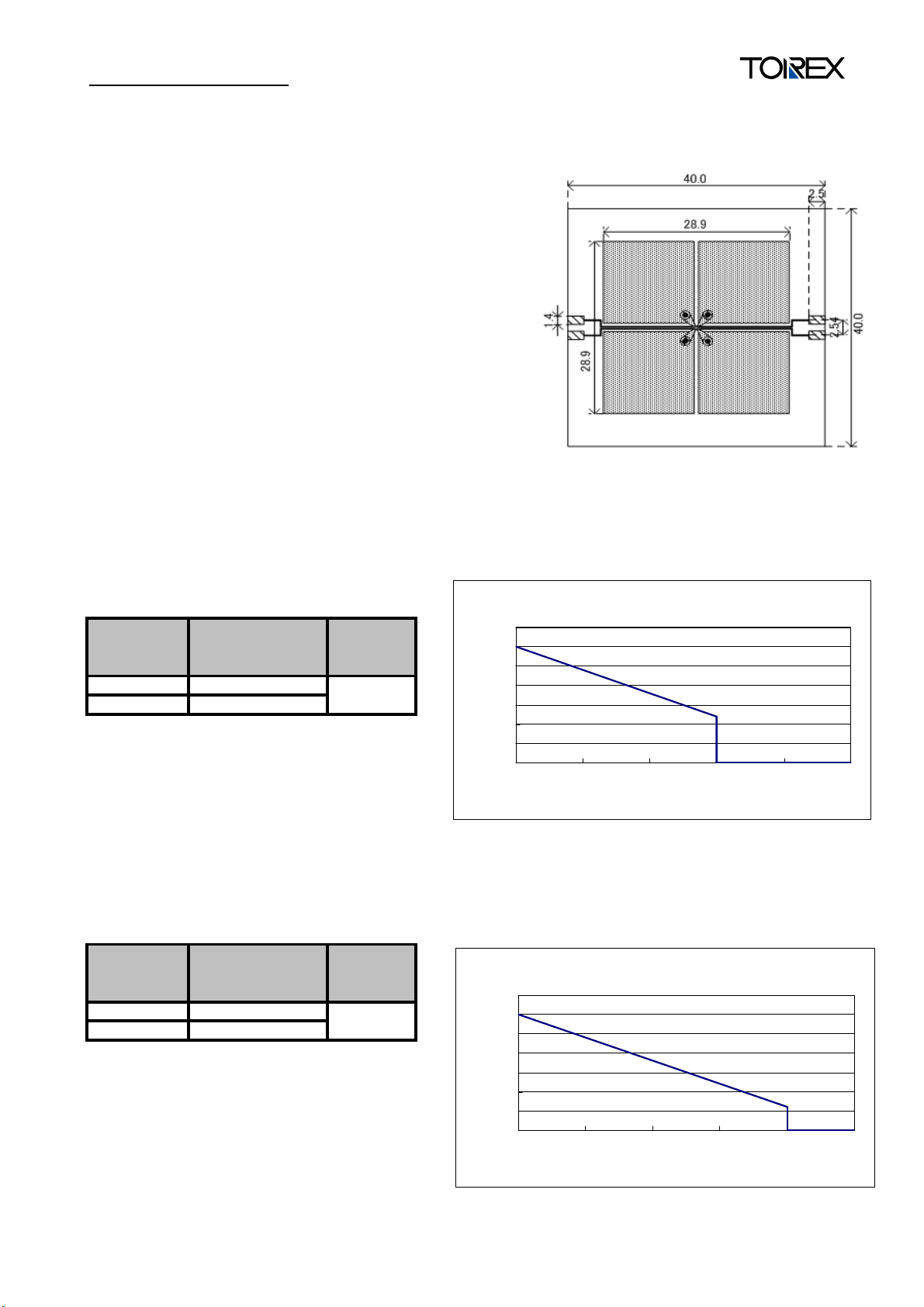
Condition: Mount on a board
Ambient: Natural convection
Soldering: Lead (Pb) free
Board: Dimensions 40 x 40 mm (1600 mm2 in one side)
Copper (Cu) traces occupy 50% of the front and
50% of the back.
The copper area is divided into four block,
one block is 12.5% of total.
The USPN-4 package has for terminals.
Each terminal connects one copper block in the front
and one in the back.
Material: Glass Epoxy (FR-4)
Thickness: 1.6 mm
Through-hole: 4 x 0.8 Diameter Evaluation Board (Unit: mm)
2. Power Dissipation vs. Ambient Temperature(85℃)
Board Mount (Tj max = 125℃)
Ambient
Temperature
(℃)
25 600
85 240
Power
Dissipation Pd
(mW)
Thermal
Resistance
(℃/W)
166.67
3. Power Dissipation vs. Ambient temperature(105℃)
Board Mount ( Tjmax=125℃)
Ambient
Temperature
(℃)
25 600
105 120
Power
Dissipation Pd
(mW)
Thermal
Resistance
(℃/W)
166.67
Pd vs Ta
Pd-Ta特性グラフ
700
600
500
400
300
200
許容損失Pd(mW)
100
0
Power Dissipation Pd(mW)
25 45 65 85 105 125
Ambient Temperature Ta(℃)
周囲温度Ta(℃)
700
600
500
400
300
200
許容損失Pd(mW)
100
0
Power Dissipation Pd(mW)
25 45 65 85 105 125
Pd-Ta特性グラフ
Pd vs Ta
周囲温度Ta(℃)
Ambient Temperature Ta(℃)
 Loading...