

TorcUP ULTRA series, ULTRA UT-3, ULTRA UT-2, ULTRA UT-7, ULTRA UT-11 Operating And Maintenance Instructions Manual


Version 1-2008
September 2008
OPERATION AND MAINTENANCE MANUAL
FOR TorcUP ULTRA UT-2, UT-3, UT-7, UT-11,
SQUARE DRIVE HYDRAULIC TORQUE WRENCHES
UTLRA Series UT-2, UT-3, UT-7, UT-11, Square Drive Hydraulic Torque Wrenches are designed for
installing and removing threaded fasteners requiring precise high torque during bolt makeup and
maximum torque during bolt breakout.
TorcUP Inc. is not responsible for customer modification of tools for applications on which TorcUP Inc.
IMPORTANT SAFETY INFORMATION ENCLOSED.
READ THIS MANUAL BEFORE OPERATING TOOL.
IT IS THE RESPONSIBILITY OF THE EMPLOYER TO PLACE THE INFORMATION IN THIS
MANUAL INTO THE HANDS OF THE OPERATOR.
FAILURE TO OBSERVE THE FOLLOWING WARNINGS COULD RESULT IN INJURY
PLACING TOOL IN SERVICE
• Always operate, inspect and maintain this tool in
accordance with American National Standards Safety
Code for Hydraulic Rams and Jacks (ANSI B30.1)
• This tool will function using an air or electric powered
hydraulic pump. Adhere to the pump safety
requirements and follow instructions when connecting
the pump to the tool.
• Use only equipment rated for the same pressure and
torque.
• Use only a hydraulic pump capable of gener a t i ng
10,000 PSI (681 bar) maximum pressure with this tool.
• Use only twin line hydraulic hose rated for 10,000 PSI
(681 bar) pressure with this tool.
• Do not interchange the male and female swivel inlets
on the tool or the connections on one end of the hose.
Reversing the inlets will reverse the power stroke cycle
and may damage the tool.
• Do not use damaged, frayed or deteriorated hoses and
fittings. Make certain there are no cracks, splits
or leaks in the hoses.
The use of other than genuine TorcUP replacement parts may result in safety hazards, decreased tool performance,
and increased maintenance, and may invalidate all warranties.
Repairs should be made only by authorized personnel. Consult your nearest TorcUP Authorized Service Center.
Refer All Communications to the Nearest TorcUP Office or Distributor.
TorcUP Inc.
Printed in U.S.A.
For Technical Support and Information Contact:
1025 Conroy Place, Easton, PA 18040
Phone: (610) 250-5800 Fax: (610) 250-2700
- 1 -
NOTICE
was not consulted.
WARNING
• Use the quick connect system to attach the hoses to the
tool and pump. Make certain the spring-loaded retaining
rings are fully engaged to prevent the connectors from
disengaging under pressure.
• When connecting hoses that have not been preloade d
with hydraulic oil, make certain the pump reservoir is
not drained of oil during start-up.
• Do not remove any labels. Replace any damaged label.
USING THE TOOL
• Do not handle pressurized hoses. Escaping oil under
pressure can penetrate the skin, causing serious injury. If
oil is injected under the skin, see a doctor immediately.
• Never pressurize uncoupled couplers. Onl y use
hydraulic equipment in a coupled system.
• Always wear eye protection when operating or
performing maintenance on this tool.
• Always wear head and hand protection and protective
clothing when operating this tool.
NOTICE
TorcUP, Inc.
E-mail: info@torcup.com
.

FAILURE TO OBSERVE THE FOLLOWING WARNING COULD RESULT IN INJURY
WARNING
USING THE TOOL
*Keep hands, loose clothing and long hair away from the
reaction arm and working area during operation. Do not
attempt to support the tool with your hands during operation.
*This tool will exert a strong reaction force. Use proper
mechanical support and correct reaction arm positioning to
control these forces. Do not position the reaction arm so that
it tilts the tool off the axis of the bolt and never use the swivel
inlets as a reaction stop.
*Avoid sharp bends and kinks that will cause severe back-up
pressure in hoses and lead to premature hose failure.
*Use accessories recommended by TorcUP.
*Use only impact sockets and accessories. Do not use hand
(chrome) sockets or accessories.
*Use only sockets and accessories that correctly fit the
bolt or nut and function without tilting the tool off the axis
of the bolt.
*This tool is not designed for working in explosive atmo-
spheres
*This tool is not insulated against electric shock. When
using this tool with a pump having an electrical power
source or circuits, follow the pump instructions for proper
grounding.
* Use only impact sockets and accessories that are appro-
priately rated for the output of the tool.
*Always use retaining pin and ring to engage the socket
to the square drive.
*Inspect sockets for signs of over use before utilizing with
tool.
CONNECTING THE TOOL
1. Attach the twin line hose to the swivel inlets of the
Square Drive Torque Wrench using the spring - loaded
quick connects ends. After making certain that they are
fully engaged, thread the safety rings tightly against the
spring–loaded retainer rings.
2. Connect the opposite ends of the hose to the Pump in the
same manner.
ADJUSTMENTS
SETTING THE SQUARE DRIVE FOR ROTATION
The position of the Square Drive when looking toward the
Shroud will determine if the tool is set to tighten or loosen
the nut. When the Square Drive extends to the left when
looking at the Shroud with the inlets away from you, the
tool is set to loosen the nut. When the Square
Drive extends to the right, the tool is set to tighten the nut. To
change the direction of rotation forModels UT-2 UT-3, UT-7
and UT-11simply push the Square Drive into the housing
until the Drive projects out the opposite side of the tool.
SETTING THE TORQUE
After determining the desired torque, use the torque con-ver-
sion chart on the Shroud or the torque conversion charts on
page 5 to determine the pressure that is necessary to achieve
that torque.
1. Connect the tool to the power supply and turn the pump on.
2. Depress the remote control button causing the pressure to
be shown on the gauge.
3. Adjust the pressure by loosening the wing nut that locks the
pressure adjustment thumbscrew. Rotate the thumbscrew
clockwise to increase the pressure and counterclockwise to
decrease the pressure. Con’t...
PLACING THE TOOL IN SERVICE
PLACING THE TOOL IN SERVICE
When decreasing pressure, always lower the pressure
below the desired point and then bring the gauge back up
to the desired pressure.
4. When the desired pressure is reached, retighten the
wing nut and cycle the tool again to confirm that the
desired pressure setting has been obtained.
SETTING THE REACTION ARM
The function of a reaction device is to hold the tool in
position against the forces generated to tighten or loosen
bolts or nuts. Hydraulic wrenches generate tremendous
force.
An improperly positioned reaction arm may
result in operator injury or damaged tooling.
Square Drive Hydraulic Wrench
Reaction Points (Dwg. 01)
Make sure the Reaction Arm is positioned correctly.
(Refer to Drawing 01).
The Reaction Arm can be positioned numerous places
within a 360
correctly positioned, it must be set within a 90
of that circle. That quadrant is the area located between
the protruding Square Drive and the bottom of the
Housing away from the Swivel Inlets. It will always be
toward the lower half of the Housing and on one side of
the Housing when tightening and the other side when
loosening.
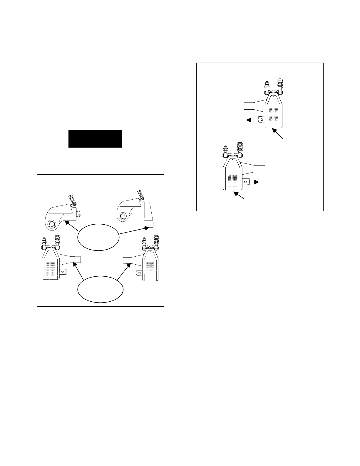
OPERATING THE WRENCH
The position of the Square Drive relative to the Shroud
determines whether the action will tighten or loosen the
nut. (Refer to Dwg. 02 for application examples).
The power stroke of the Piston Assembly will always
turn the Square Drive toward the Shroud.
WARNING
REACTION
REACTION
CONTACT
CONTACT
POINTS
POINTS
REACTION
REACTION
CONTACT
CONTACT
POINTS
POINTS
O
circle. However, for the Arm to be
O
quadrant
WRENCH POSITIONS
Square Drive Position for Loosening and
Tightening (Dwg. 02)
FOR LOOSENING
FOR LOOSENING
FOR LOOSENING
SHROUD
SHROUD
SHROUD
FOR TIGHTENING
FOR TIGHTENING
FOR TIGHTENING
SHROUD
SHROUD
SHROUD
1. Place the Square Driver in the socket and the socket
on the nut. Make certain the Square Driver and socket
are the correct size for the nut and that the Driver fully
engages the socket and that the socket is pinned to the
Driver with retaining ring and pin.
2. Position the reaction arm or surface against an
adjacent nut, flange or solid system component. Make
certain that there is clearance for the hoses, swivels,
inlets and End Plug. DO NOT allow the tool to react
against the hoses, swivels, inlets or End Plug.
3. After having turned the Pump on and presetting the
pressure for the correct torque, depress the remote
control button to advance the Piston Assembly
4. When the wrench is started, the reaction surface of the
wrench or Reaction Arm will move against the contact
point and the nut will begin to turn.
5. When the nut is no longer turning and the Pump
Gauge reaches the preset pressure, release the remote
control button. The piston rod will retract when the
button is released and under normal conditions, an
audible “click” will be heard as the tool resets itself.
6. Continue to cycle the tool until it “stalls” and the
preset PSI/torque has been attained.
7. Once the nut stops rotating, cycle the tool one last
time to achieve total torque.
- 3 -

PLACING THE TOOL IN SERVICE
LUBRICATION
Marine Moly Grease
Lubrication frequency is dependent on factors known only to the user. The amount of contaminants in the work area is one
factor. Tools used in a clean room environment will obviously require less service than a tool used out-doors and dropped
in loose dirt or sand. Marine Moly Grease is formulated not to wash out of the tool in areas where lubrication is critical.
Whenever lubrication is required, lubricate as follows:
1. Remove the Drive Plate, Ratchet, Segment Pawl and Drive Sleeves as instructed in the Maintenance Section and wash
the components in a suitable cleaning solution in a well–ventilated area.
2. After drying the components, wipe a film of Marine Moly Grease onto the wear surface of both Drive Sleeves and the
ends of the Ratchet.
3. Spread a light film of Marine Moly Grease onto the inner face and both sides of the Drive Plate.
Do not pack the teeth of the Segment Pawl or Ratchet with lube. It can prevent the teeth from engaging properly.
4. Place a daub of Marine Moly Grease in the piston rod recess of the Drive Plate before linking the Piston Rod to the
Drive Plate at assembly.
CRITICAL LUBRICATION
It is imperative to lubricate the piston rod recess of the Drive Plate to Piston Rod
contact area every 20 hours of continuous duty cycling.
Lubricate as follows:
1. Remove Shroud Screws, Shroud, and Roll Pin.
2. Pry the Drive Plate assembly forward from the Piston Rod to expose the recessed contact area in the Drive Plate.
3. With a rag, wipe clean the area and apply a sizeable amount of Marine Moly Grease.
4. Reassemble as instructed in the maintenance section.
- 4 -

UT Series Torque Conversion Chart
P.S.I./FT./lbs Bar/N.M.
UT-2
P.S.I.
1,000 127 330 740 1,090 68 172 447 1,003 1,478
1,200 152 395 888 1,308 82 206 535 1,204 1,773
1,400 178 460 1,036 1,526 95 241 624 1,404 2,069
1,600 203 525 1,185 1,745 109 275 712 1,606 2,366
1,800 229 590 1,332 1,962 122 310 800 1,806 2,660
2,000 255 655 1,470 2,210 136 346 888 1,993 2,996
2,200 279 722 1,617 2,430 150 378 979 2,192 3,294
2,400 305 789 1,765 2,652 163 413 1,070 2,393 3,595
2,600 330 856 1,911 2,873 177 447 1,160 2,591 3,895
2,800 356 923 2,058 3,095 190 483 1,251 2,790 4,196
3,000 380 990 2,210 3,340 204 515 1,342 2,996 4,528
3,200 406 1,058 2,358 3,560 218 550 1,434 4,826 4,826
3,400 432 1,126 2,505 3,785 231 586 1,526 3,395 5,131
3,600 457 1,194 2,652 4,005 245 620 1,619 3,595 5,429
3,800 483 1,262 2,800 4,230 258 655 1,711 3,796 5,734
4,000 510 1,330 2,960 4,400 272 691 1,803 4,013 5,965
4,200 533 1,397 3,108 4,620 286 723 1,894 4,213 6,263
4,400 559 1,464 3,256 4,840 299 758 1,985 4,414 6,561
4,600 584 1,531 3,405 5,060 313 792 2,075 4,616 6,859
4,800 609 1,598 3,552 5,280 326 826 2,166 4,815 7,158
5,000 635 1,665 3,716 5,500 340 861 2,257 5,037 7,456
5,200 660 1,732 3,865 5,720 354 895 2,348 5,239 7,754
5,400 686 1,799 4,013 5,940 367 930 2,439 5,440 8,052
5,600 711 1,856 4,162 6,160 381 964 2,516 5,642 8,350
5,800 737 1,933 4,311 6,380 394 999 2,620 5,843 8,649
6,000 760 2,000 4,440 6,620 408 1,030 2,711 6,019 8,974
6,200 787 2,065 4,588 6,838 422 1,067 2,799 6,219 9,270
6,400 813 2,130 4,736 7,060 435 1,102 2,887 6,420 9,571
6,600 838 2,195 4,884 7,280 449 1,136 2,976 6,621 9,869
6,800 864 2,260 5,032 7,500 462 1,171 3,064 6,821 10,167
7,000 890 2,325 5,180 7,710 476 1,206 3,152 7,022 10,452
7,200 914 2,398 5,328 7,927 490 1,239 3,251 7,223 10,746
7,400 940 2,461 5,476 8,147 503 1,274 3,336 7,423 11,044
7,600 965 2,529 5,625 8,368 517 1,308 3,428 7,625 11,344
7,800 991 2,597 5,772 8,588 530 1,343 3,520 7,825 11,642
8,000 1,015 2,665 5,920 8,820 544 1,376 3,613 8,025 11,956
8,200 1,041 2,731 6,068 9,045 558 1,411 3,702 8,226 12,261
8,400 1,067 2,797 6,216 9,265 571 1,446 3,792 8,426 12,560
8,600 1,092 2,863 6,365 9,485 585 1,480 3,881 8,628 12,858
8,800 1,118 2,929 6,512 9,705 598 1,516 3,971 8,828 13,156
9,000 1,145 2,995 6,660 9,930 612 1,552 4,060 9,028 13,461
9,200 1,168 3,062 6,808 10,148 626 1,583 4,151 9,229 13,757
9,400 1,194 3,129 6,956 10,368 639 1,619 4,242 9,430 14,055
9,600 1,219 3,196 7,105 10,588 653 1,652 4,332 9,632 14,353
9,800 1,245 3,263 7,252 10,810 666 1,688 4,423 9,831 14,654
10,000 1,270 3,330 7,400 11,010 680 1,722 4,514 10,031 14,925
UT-3 UT-7 UT-11
ft./lbs. ft./lbs. ft./lbs. ft./lbs.
UT-2 UT-3 UT-7 UT-11
Bar
N.m. N.m. N.m. N.m.
- 5 -

UT – 2, 3, 7 and 11 Series Wrench
- 6 -

Part Numbers for Ordering
1 Housing UT-2-01 UT-3-01 UT-7-01 UT-11-01
2 Housing Threaded Plug N/A N/A TU-7-39 UT-11-39
3 Reaction Arm TU-2-03-1 TU-3-03-1 TU-7-03-1 TU-11-03-1
4 Reaction Arm Cover TU-2-03-7 TU-3-03-7 TU-7-03-7 TU-11-03-7
5 Cover Screws TU-2-03-8 TU-3-03-8 TU-7-03-8 TU-11-03-8
6 Reaction Arm Spring TU-2-03-6 TU-3-03-6 TU-7-03-6 TU-11-03-6
7 Locking Pin UT-2-03-3 UT-3-03-3 UT-7-03-3 UT-11-03-3
8 Retract Button UT-2-03-4 UT-3-03-4 UT-7-03-4 UT-11-03-4
9 Reaction Arm Screw UT-2-03-5 UT-3-03-5 UT-7-03-5 UT-11-03-5
10 Spline sleeve UT-2-03-2 UT-3-03-2 UT-7-03-2 UT-11-03-2
11 Square Drive TU-2-11-1 TU-3-11-1 TU-7-11-1 TU-11-11-1
12 Ball Plunger TU-2-11-3 TU-3-11-3 TU-7-11-3 TU-11-11-3
14 Locking Pin TU-2-11-2 TU-3-11-2 TU-7-11-2 TU-11-11-2
16 Sleeve UT-2-13 UT-3-13 UT-7-13 UT-11-13
17 Ratchet UT-2-05 UT-3-05 UT-7-05 UT-11-05
18 Drive Plate UT-2-09 UT-3-09 UT-7-09 UT-11-09
19 Drive Segment UT-2-07 UT-3-07 UT-7-07 UT-11-07
20 Drive Segment Spring TU-2-27 TU-3-27 TU-7-27 TU-11-27
21 Roll Pin TU-2-19 TU-3-19 TU-7-19 TU-11-19
22 N/A
23 Smalle y Ring TU-2-43 TU-3-43 TU-7-43 N/A
24 End Plug UT-2-15 UT-3-15 UT-7-15 UT-11-15
25 End Plug Seal TU-2-37 TU-3-37 TU-7-37 TU-11-37
26 Piston Seal TU-2-33 TU-3-33 TU-7-33 TU-11-33
27 Piston Rod Assembly TU-2-17 TU-3-17 TU-7-17 TU-11-17
28 Gland Seal TU-2-35 TU-3-35 TU-7-35 TU-11-35
29 Cylinder Gland TU-2-21 TU-3-21 TU-7-21 TU-11-21
30 Rod Seal TU-2-31 TU-3-31 TU-7-31 TU-11-31
31 Shroud TU-2-23 TU-3-23 TU-7-23 TU-11-23
32 Shroud Screws TU-2-25 TU-3-25 TU-7-25 TU-11-25
33 Swivel (2 req) STU-4M-4M STU-4M-4M STU-4M-4M STU-4M-4M
34 Coupler Set HC-S-100 HC-S-100 HC-S-100 HC-S-100
35
36
40 Gland Wrench TU-2-GW TU-3-GW TU-7-GW TU-11-GW
~ Reaction Arm Assembly UT-2-03 UT-3-03 UT-7-03 UT-11-03
~ Square Drive Assembly UT-2-11 UT-3-11 UT-7-11 UT-11-11
Part UT-2 UT-3 UT-7 UT-11
- 7 -

Maintenance Section
Always turn off the power supply, bleed off hydraulic
fluid from the hose connections on the cylinder
assembly and disconnect the hoses before attempting
to repair or perform maintenance on this tool.
Always wear eye protection when operating or
performing maintenance on this tool.
General Instructions
1. Do not disassemble the tool any further than necessa ry
to replace or repair damaged parts.
2. Use extra care not to score, nick or damage surfaces
that will contain hydraulic oil under pressure.
3. Whenever grasping a tool in a vise, always use
leather–covered or copper–covered vise jaws to protect
the surface of the part and help prevent distortion. This is
particularly true of threaded members and housings.
4. Do not remove any part that is a press fit in or on an
assembly unless the removal of that part is necessary for
repairs or replacement.
5. Do not disassemble the hydraulic cylinder assem bly
unless you have a complete set of seals and o–rings for
replacement.
6. Use only British Standard fractional size tools when
disassembling these tools.
Disassembly of the Reaction Arm Assembly
1. Push the Reaction Arm Retract Button (8) toward the
Reaction Arm Boot (4) and separate the Reaction
Arm Assembly from the Housing (1).
2. While holding the Button down, use a hex wre nc h to
unscrew and remove the Reaction Arm Spline Screw (9).
3. Apply some downward pressure to the Reaction Arm
Engagement Pin (7) and unscrew the Reaction Arm
Retract Button from the Engagement Pin.
4. Remove the Engagement Pin by sliding it out of the
top of the Reaction Arm (3).
5. Pull the Reaction Arm Splined Sleeve (10) out of the
Reaction Arm.
6. Using a hooked tool through the Spline Screw
opening, pull the Reaction Arm Pin Spring (6) out of the
Reaction Arm.
7. To remove the Reaction Arm Boot, use a hex wrench
to unscrew the two Boot Mounting Screws (5) and pull
the Boot off the Reaction Arm.
Disassembly of the Square Drive Tool
1. Before attempting to disassemble a square drive tool,
connect the tool to a pump and operate the tool until the
Piston Assembly (27) is in the fully retracted position.
2. Grasp the Housing (1) in copper–covered or leather–
covered vise jaws with the inlet end upward and using a
WARNING
DISASSEMBLY
3/4” wrench, unscrew and remove the two Swivel Inlets
(33) with their attached Couplers (34).
3. Remove the Housing from the vise jaws and with the
inlet openings over a container to catch the oil, drain as
much hydraulic oil as possible from the Housing.
4. Grasp the Cylinder Housing in copper–covered or
leather–covered vise jaws with the Shroud (31) upward.
In the following step the Shroud will spring to a
straightened position when the Screws at one end are
removed. Hold the Shroud in position until the
Screws are removed and control the flex of the loose
end.
5. Use a hex wrench to unscrew and remove the Shroud
Mounting Screws (32). Remove the Shroud.
6. If the Piston Assembly is not fully retracted, use a
brass drift or brass hammer to tap the Assembly inward
until the Retract Pin (21) aligns with the cross holes in
the Housing. Use a small drift to tap the Retract Pin out
of the Drive Plate (18) and Piston Assembly through the
openings in the Housing.
7. For UT-2, UT-3, UT-7 and UT-11 models, insert a
hex wrench through the larger opening in the Square
Drive and unscrew the Square Drive Locking Pin (14)
inward against the Square Drive Spring (13) while
pulling or pushing the Square Drive out of the tool.
8. For UT-2, UT-3, UT-7 and UT-11 models, remove
the Drive Plate, assembled with the Ratchet (17),
Segment Pawl (19) and Segment Pawl Springs (20) from
between the ears of the Housing. Using finger press u re,
push the Drive Sleeves (16) inward to remove them from
the Housing.
9. Being careful not to let the springs eject from the
assembly, slide the Ratchet, Segment Pawl and Segment
Pawl Springs out of the Drive Plate.
- 8 -
CAUTION

NOTICE
The Cylinder Gland is staked into the Housing to
prevent it from loosening due to vibration or
turbulence in the hydraulic oil flow. The stake point
must be drilled out before attempting to remove the
Cylinder Gland.
10. Locate the stake point on the threads of the Cylinder
Gland (29) and Housing. Using a 1/16” drill bit centered
on the stake point, drill approximately 3/32” deep in one
continuous motion to remove the thread and interference
at that point.
11. Engage the pins of the Cylinder Gland Wrench (40)
with the holes in the Cylinder Gland and using a socket
on the hex of the Wrench unscrew and remove the
Cylinder Gland. Should the Gland not rotate freely a fte r
initial breakout, additional drilling, in small increments,
may be required to remove the obstruction.
12. If the Piston Rod Seal (30) must be replaced, remove
it from the central opening of the Gland.
13. If the Cylinder Gland Seal (28) must be replaced,
remove it from the groove at the bottom of the threads in
the Housing.
In the following step, DO NOT grasp the shaft of the
Piston Assembly with any device that will mar, bur or
otherwise damage the shaft or the drive plate end of
the shaft.
14. Pull the Piston Assembly out of the Housing. If the
Assembly is tight in the Housing and difficult to pull,
inject air into the inlet opening while holding the
Housing over a container that will not damage the
Piston when it is expelled. If an air hose is not available,
temporarily attach the advance line from the pump and
cycle the tool to advance the Piston out of the Housing.
Hydraulic oil will be emitted with the Piston, so the
assembly must be held over a non–damaging container.
15. If the Piston Seal (26) must be replaced, remove it
from the Piston.
16. Push on the small end of the End Plug (24) to
remove it from the Housing. If the End Plug is tight in
the Housing, insert a flat face drift into the hole in the
center of the small shaft, and without cocking the Plug,
tap it out of the Housing.
17. If the End Plug Seal (25) must be replaced, remove it
from the End Plug.
18. If the Splined Sleeve Seat (23) needs replacement,
use a thin blade screwdriver to work it out of the groove
in the Housing.
ASSEMBLY
General Instructions
1. Use extra care not to score, nick or damage surfaces
that will contain hydraulic oil under pressure.
2. Whenever grasping a tool in a vise, always use
leather–covered or copper–covered vise jaws to protect
the surface of the part and help prevent distortion. This is
particularly true of threaded members and housings.
3. Apply o–ring lubricant to all o–rings before final
assembly.
Assembly of the Square Drive Tool
1. If the Splined Sleeve Seat (23) was removed from the
Housing (1), install it in the internal groove near the inlet
end of the Housing.
2. Grasp the Housing in leather–covered or cop per–
covered vise jaws with the inlet end downward.
3. Apply o–ring lubricant to the End Plug Seal (25) and
install it in the annular groove at the large end of the
End Plug (24).
4. Insert the assembled End Plug, small end leading, into
the piston bore of the Housing and using a brass drift in
the center of the End Plug; tap the assembly to the
bottom of the bore without cocking it.
5. Apply o–ring lubricant to the Piston Seal (26) and
install it in the annular groove at the large end of the
Piston Assembly (27).
6. If the Piston Rod Seal (30) was removed from the
Cylinder Gland (29), install a new Seal, lip end trailing,
into the central opening of the Gland.
7. Apply o–ring lubricant to the Cylinder Gland Seal
(28) and install it in the housing recess at the bottom of
the threads for the Cylinder Gland.
8. Insert the Piston Assembly, shaft end leading, into the
threaded end of the Gland through the Gland Seal and
push it inward until the large end of the Piston is against
the end of the Gland.
9. Start threading the Cylinder Gland into the Housing.
Using the Cylinder Gland Wrench (40) and a socket,
tighten the Gland in the Housing.
10. Reposition the assembled tool in the vise jaws with
the inlet end upward.
11. Wrap the threads of the Swivel Sets (33) with Teflon
Tape. Thread the swivel with the male hose Coupler (34)
into the threaded hole on the right (Marked A) side of
the Housing when looking from the inlet end of the tool
with the Square Drive downward. Thread the swivel
with the female hose Coupler into the other hole
(Marked R).
12. Connect the hoses from the pump, turn the power on
and cycle the tool several times to determine if the Gland
is leaking fluid.
13. If the Gland is leaking, disconnect the hoses and
power supply, determine the cause of the leak and take
whatever steps are necessary to correct the problem.
If the Gland is not leaking, operate the tool to fully
retract the Piston Assembly, disconnect the hoses and
power supply and reposition the tool in the vise jaws
with the inlet end downward.
- 9 -

NOTICE
In the following step, the Cylinder Gland must be
staked into the Housing to prevent it from loosening
due to vibration or turbulence in the hydraulic oil
flow. Use a center punch with a 60 degree included
angle and do not deform the stake point beyond 3/64”
deep. Do not attempt to use the previously staked
position and leave housing clearance at the new
position for a 1/16” drill bit should the Gland require
removal in the future.
14. Stake the thread of the Gland and Housing at the
open area between the ears of the Housing that holds the
Square Drive (11). Make certain both the Housing and
Gland are deformed at the stake point.
15. If the Ball Plungers (22) were removed, install them
in the Housing and thread them inward until only the ball
projects into the driver sleeve opening.
16. Wipe a thin film of Marine Moly Grease on the sides
of the Drive Plate (18), as well as the inner race and
piston rod recess of the Drive Plate.
17. Insert the Ratchet (17) in the Drive Plate.
18. Position the Segment Pawl (19) at the cavity in the
Drive Plate. Make certain the teeth of the Pawl will
properly engage the teeth of the Ratchet. If they will not
engage properly, reverse the Ratchet in the Drive Plate.
Insert the Segment Pawl Springs (20) into the holes in
the Pawl, and while compressing the springs with finger
pressure, slide the Pawl and springs into the Drive Plate.
19. For UT-2, UT-3, UT-7 and UT-11 models, proceed
as follows:
a) a) From inside the housing ears, insert a Driver
Sleeve (16) into each ear with the detent end of the
Sleeve trailing. The ball of the Ball Plunger must
engage the detent holes encircling the Sleeve.
b) b) Position the assembled Drive Plate between the
ears of the Housing with the notch for the piston rod
toward the rod end.
c) c) Insert a wire rod or hex wrench through the
opening of the Square Drive Hollow Lock ( 15 ) and
push the Square Drive Locking Pin (14) inward
against the Square Drive Spring (13) while inserting
the Square Drive (11) into the Ratchet. It may be
necessary to individually rotate the Driver Sleeves
and Ratchet to align the squares for the Square
Drive.
In the following step, the side of the Housing that the
square protrudes from will determine the direction of
square drive rotation. If the square extends to the
left side when looking from the inlet end of the
NOTICE
Housing, rotation will be clockwise to tighten. A
right side extension is counterclockwise for loosening.
a) Insert the splined end of the Square Drive (11)
through the Driver Sleeves and Ratchet. Install the
Square Drive Retaining Screw (35) in the end of the
Square Drive and tighten it.
20. Insert the Retract Pin (21) into the hole in the Drive
Plate through the hole in the Housing. Use a drift and
hammer to tap the Pin into the Plate and rod to secure the
assembly. Make certain the Pin does not protrude
beyond the sides of the Drive Plate.
21. For UT-11 model , use a hex wrench to install the
two Retract Pin Hole Plugs (2) flush with the sides of the
Housing.
22. Place one end of the Shroud (31) on the Housing and
using a hex wrench, install the Shroud Mounting Screws
(32) at that end.
23. Bend the Shroud around the Housing and install the
remaining Mounting Screws.
Assembly of the Reaction Arm Assembly
1. If the Reaction Arm Boot (4) was removed, push it
onto the end of the Reaction Arm (3) and using a hex
wrench, secure it by installing the two Boot Mounting
Screws (5).
2. Insert the Reaction Arm Pin Spring (6) in the
downward, blind hole below the bore for the Reaction
Arm Splined Sleeve (10).
3. Position the Reaction Arm Splined Sleeve in the bore
of the Reaction Arm with the small hub end trailing and
the slightly larger hole through the side of the Sleeve
upward. Align the holes through the Sleeve with the
holes in the Reaction Arm.
4. Insert the Reaction Arm Engagement Pin (7), flat end
leading, through the Sleeve into the hole against the Pin
Spring. Rotate the Pin so that the vertical flat on the end
of the Pin faces away from the tool end of the Arm.
5. Push downward on the Engagement Pin until the
threaded hole in the side of the Pin is visible through the
slot in the end of the reaction arm away from the tool.
6. For UT-2, UT-3, UT-7 and UT-11 models, apply a
suitable thread–locking compound to the threads of the
Reaction Arm Retract Button (8) and using a
screwdriver, screw the Button tightly into the threaded
hole in the Engagement Pin.
7. Using a hex wrench, thread the Reaction Arm Spline
Screw (9) into the top of the Reaction Arm until the
unthreaded end enters the hole in the Splined Sleeve and
the threads bottom out.
- 10 -

Trouble Probable Cause Solution
Piston will not advance or retract
Piston will not retract
Cylinder will not build up
pressure
Square Drive will not turn
Tool tightens immediately when
turned on
Pump will not build up pressure
Troubleshooting Guide
Couplers are not securely
attached to the tool or pump
Coupler is defective Replace any defective Coupler.
Defective remote control switch
Dirt in the direction-control valve
of the pump unit
Hose connections reversed
Retract hose not connected Connect the retract hose securely
Retract pin broken Replace the broken pin and/or spring
Piston Seal and/or End Plug Seal
leaking
Coupler is defective Replace any defective Coupler
Grease or dirt build up in the
teeth of the Ratchet and Segment
Pawl
Worn or broken teeth on Ratchet
an/or Segment Pawl
Hose connections are reversed
Defective relief valve
Air supply too low or air hose too
small
Electric power source is too low
Check the Coupler connections and
make certain that they are connected.
Replace the switch and/or control
pendent
Disassemble the pump and clean the
direction-control valve.
Make certain the advance on the
pump is connected to the advance on
the tool and retract on the pump is
connected to the retract on the tool.
Replace any defective O-rings
Disassemble the Ratchet and clean the
grease or dirt out of the teeth
Replace any worn or damaged parts
Depress the advance button to release
the tool; shut the pump off in the
advance position and reverse the hose
connection
Inspect, adjust or replace the relief
valve
Make certain the air supply and hose
size comply with the pump manual
recommendations.
Make certain the amperage, voltage
and any extension cord size comply
with the pump manual requirements
Pressure reading erratic Defective Gauge Replace the Gauge
Nut Returns with retract stroke
SAVE THESE INSTRUCTIONS. DO NOT DESTROY.
Defective Gauge Replace the Gauge
Low oil level Check and fill the pump reservoir
Clogged filter
Ball Plungers are not engaging
the Drive Sleeves
Inspect, clean and/or replace the
pump filter
Thread the Ball Plungers to the
correct depth in the Housing.
- 11 -
 Loading...