

Page 1
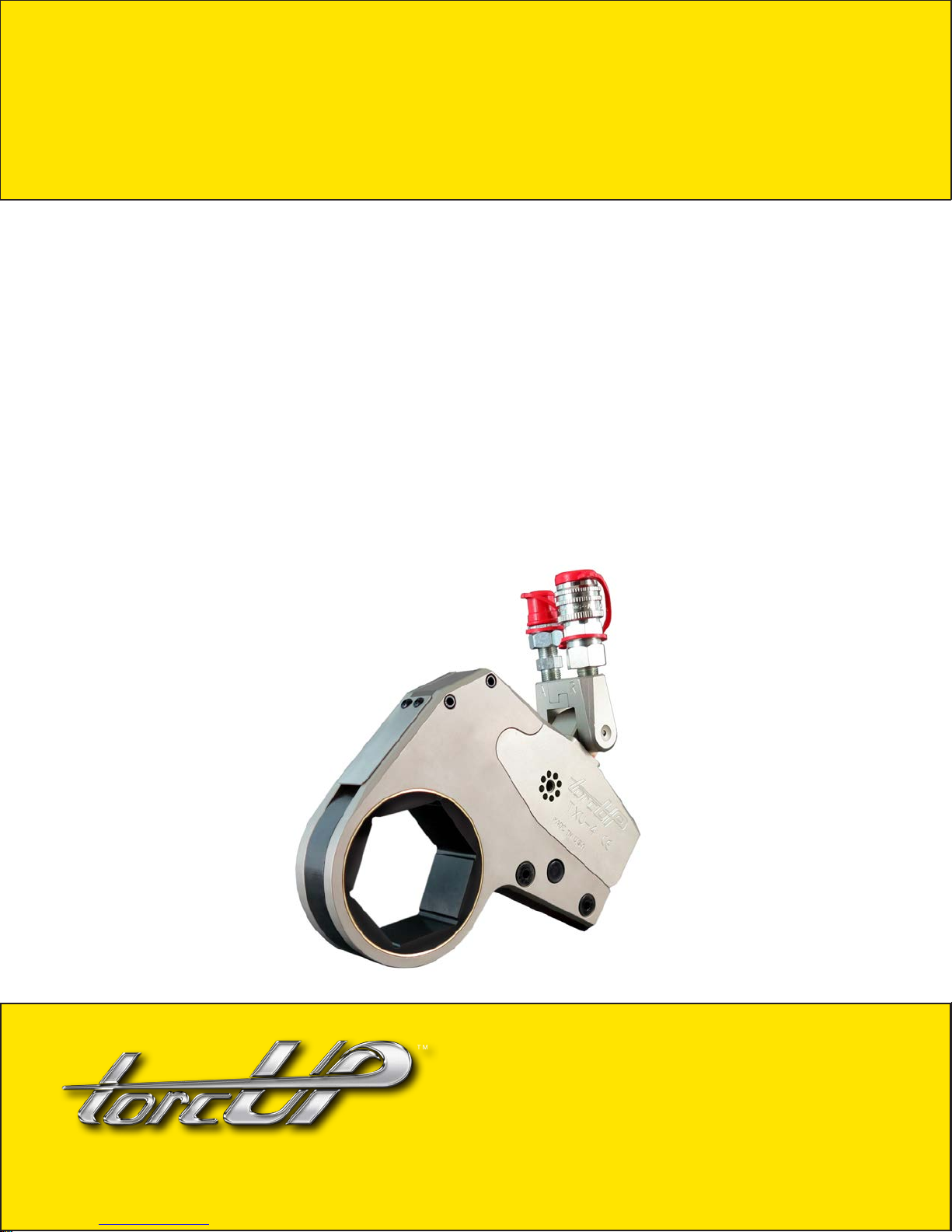
TXU Series
OPERA TION AND MAINTENANCE
MANUAL
TXU Series Uniswivel Low Prole
Hydraulic Torque Wrenches
MODELS TXU-2, TXU-4, TXU-8 and TXU-16
1025 Conroy Place, Easton, PA. 18040 U.S.A.
Phone: +1 610-250-5800
Fax: +1 610-250-2700
Toll Free: 1-888-TORCUP-1
Email: [email protected]
Website: www.torcup.com
Page 2

Operational and Maintenance Manual for TorcUP
TXU-2, TXU-4, TXU-8, and TXU-16
Uniswivel Low Prole Hydraulic Torque Wrenches
Version 2: 2016 September
NOTICE
Series TXU-2, TXU-4, TXU-8, and TXU-16 Low Prole Hydraulic Torque Wrenches are designed for
installing and removing threaded fasteners having minimal wrench clearance and requiring precise high
torque during bolt makeup and maximum torque for bolt breakout.
TorcUP Inc. is not responsible for customer modication of tools for applications on
which TorcUP Inc. was not consulted.
WARNING
IMPORTANT SAFETY INFORMATION ENCLOSED.
READ THIS MANUAL BEFORE OPERATING TOOL.
IT IS THE RESPONSIBILITY OF THE EMPLOYER TO PLACE THE INFORMATION IN THIS
MANUAL INTO THE HANDS OF THE OPERATOR.
FAILURE TO OBSERVE THE FOLLOWING WARNINGS COULD RESULT IN INJURY.
USING THE TOOL
• Always operate, inspect and maintain this tool in accordance with American National Standards
Safety Code for Hydraulic Rams and Jacks (ANSI B30.1).
• This tool will function using an air or electric powered hydraulic pump. Adhere to the pump safety
requirements and follow instructions when connecting the pump to the tool.
• Use only equipment rated for the same pressure and torque.
• Use only a hydraulic pump capable of generating 10,000 psi (681 bar) maximum pressure with this
tool.
• Use only twin line hydraulic hose rated for 10,000 psi (681 bar) pressure with this tool.
• Do not interchange the male and female swivel inlets on the tool or the connections on one end of
the hose. Reversing the inlets will reverse the power stroke cycle and may damage the tool.
• Do not use damaged, frayed or deteriorated hoses and ttings. Make certain there are no cracks,
splits or leaks in the hoses.
• Use the quick connect system to attach the hoses to the tool and pump.
• When connecting hoses that have not been preloaded with hydraulic oil, make certain the pump
reservoir is not drained of oil during start-up.
• Do not remove any labels. Replace any damaged label.
• Do not handle pressurized hoses. Escaping oil under pressure can penetrate the skin, causing
serious injury. If oil is injected under the skin, see a doctor immediately.
• Never pressurize uncoupled couplers. Only use hydraulic equipment in a coupled system.
• Always wear eye protection when operating or performing maintenance on this tool.
• Always wear head and hand protection and protective clothing when operating this tool.
The use of other than genuine TorcUP replacement parts may result in safety
hazards, decreased tool performance, increased maintenance, and may invalidate
all warranties. Repairs should be made only by authorized personnel. Consult
your nearest TorcUP Authorized Service Center.
Refer All Communications to the Nearest TorcUP Ofce or Distributor.
For Technical Support & Information Contact:
TorcUP Inc.
1025 Conroy Place, Easton, PA 18040 USA
Phone: +1 610-250-5800 Fax:+1 610-250-2700
email: [email protected]
1
Page 3
WARNING
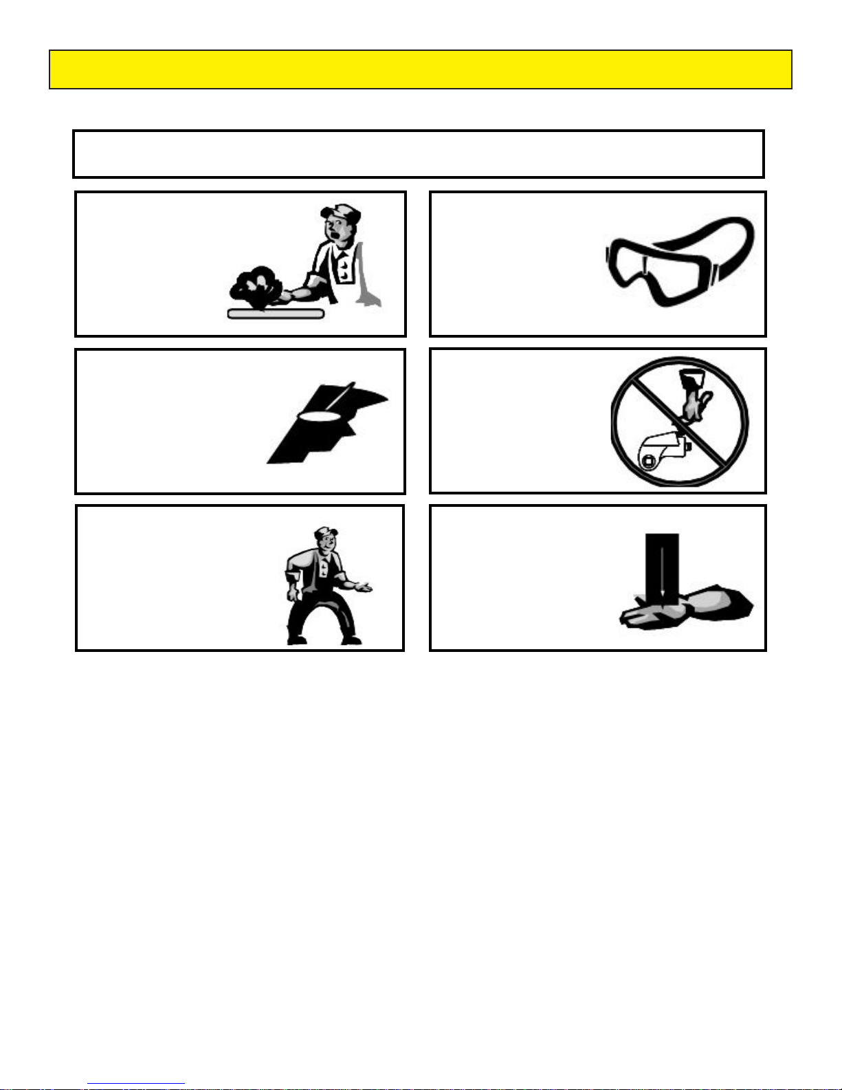
FAILURE TO OBSERVE THE FOLLOWING WARNINGS COULD RESULT IN INJURY
Do NOT Exceed Maximum Pressure. See Torque Chart with Tool. Damage May Occur.
Do not use damaged,
frayed or deteriorated
hydraulic hoses
and ttings.
Always wear ear
protection
when operating
this tool.
Keep body stance
balanced and rm.
Do not overreach
when operating
this tool.
Always wear eye
protection
when operating or
performing
maintenance
on this tool.
Do not carry
the tool
by the hose.
The Torque Reaction Arm must be
positioned against a positive stop.
Do not use the arm as a dead
handle. Take all precautions to
make certain the operator’s hand
cannot be pinched between the
arm and a solid object.
USING THE TOOL
• Keep hands, loose clothing and long hair away from the reaction arm and working area during operation.
• This tool will exert a strong reaction force. Use proper mechanical support and correct reaction arm
positioning to control these forces. Do not position the reaction arm so that it tilts the tool off the axis of the
bolt and never use the swivel inlets as a reaction stop.
• Avoid sharp bends and kinks that will cause severe back-up pressure in hoses and lead to premature hose
failure.
• Use accessories recommended by TorcUP.
• Use only impact sockets and accessories. Do not use hand (chrome) sockets or accessories.
• Use only sockets and accessories that correctly t the bolt or nut and function without tilting the tool off the
axis of the bolt.
• This tool is not insulated against electric shock.
• This equipment must not be operated or serviced unless the operator read the operating instructions and
fully understands the purpose, consequences and procedure of each step.
• When operating a larger tool (TXU-16) above waist height, employ a secondary means of support for safety
purposes. A tool sling or chains may be used. Consult your safety department for further suggestions.
Depending on the working environment your local health and safety regulations may require
you wear protective gear (i.e. safety shoes, hard hat, gloves, coveralls, etc.). In case external
forces are exerted on the equipment, non-compliance with these regulations may result in
injury. EAR PROTECTION MUST BE WORN WHEN OPERATING THIS TOOL.
2
Page 4
PLACING THE TOOL IN SERVICE
CONNECTING THE TOOL
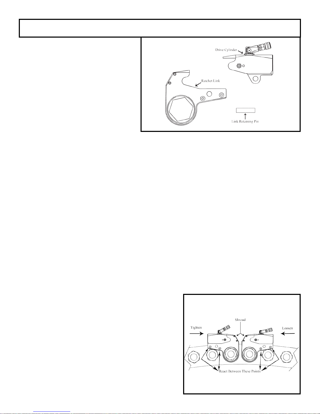
1. Attach the twin line hose to the swivel
inlets of the low prole drive cylinder
using the spring–loaded quick connect
ends.
2. Connect the opposite ends of the hose
to the pump in the same manner.
3. Push the link retaining pin out of the
low prole drive cylinder.
4. Mate the selected ratchet link to the
cylinder by inserting the end of the
cylinder opposite the swivel inlets
between the side plates of the ratchet
link. (Refer to Dwg. 1)
5. Align the holes for the link retaining pin and insert the pin through the side plates and cylinder to keep
the units joined together.
Dwg. 1
SETTING THE TORQUE
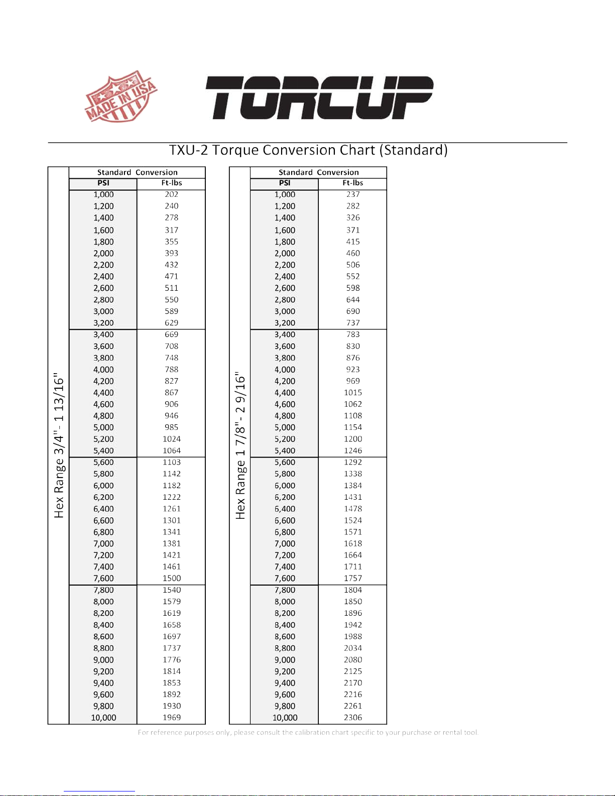
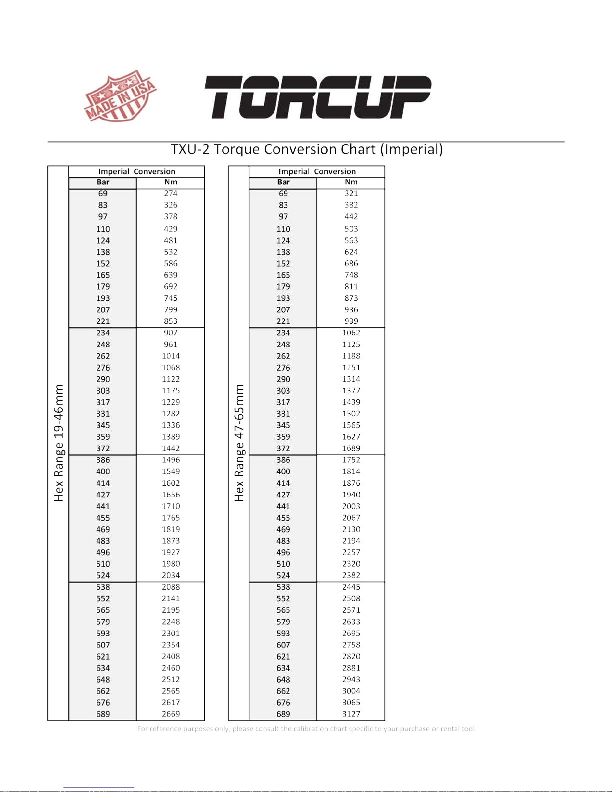
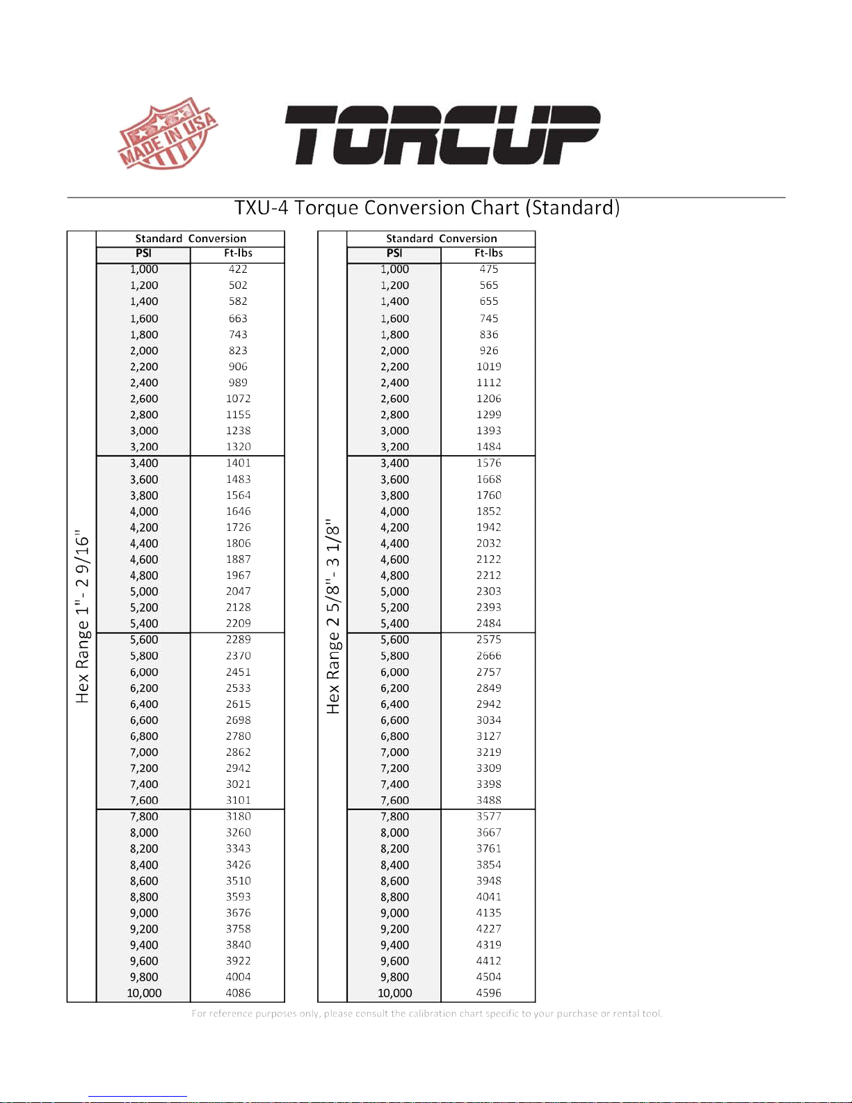
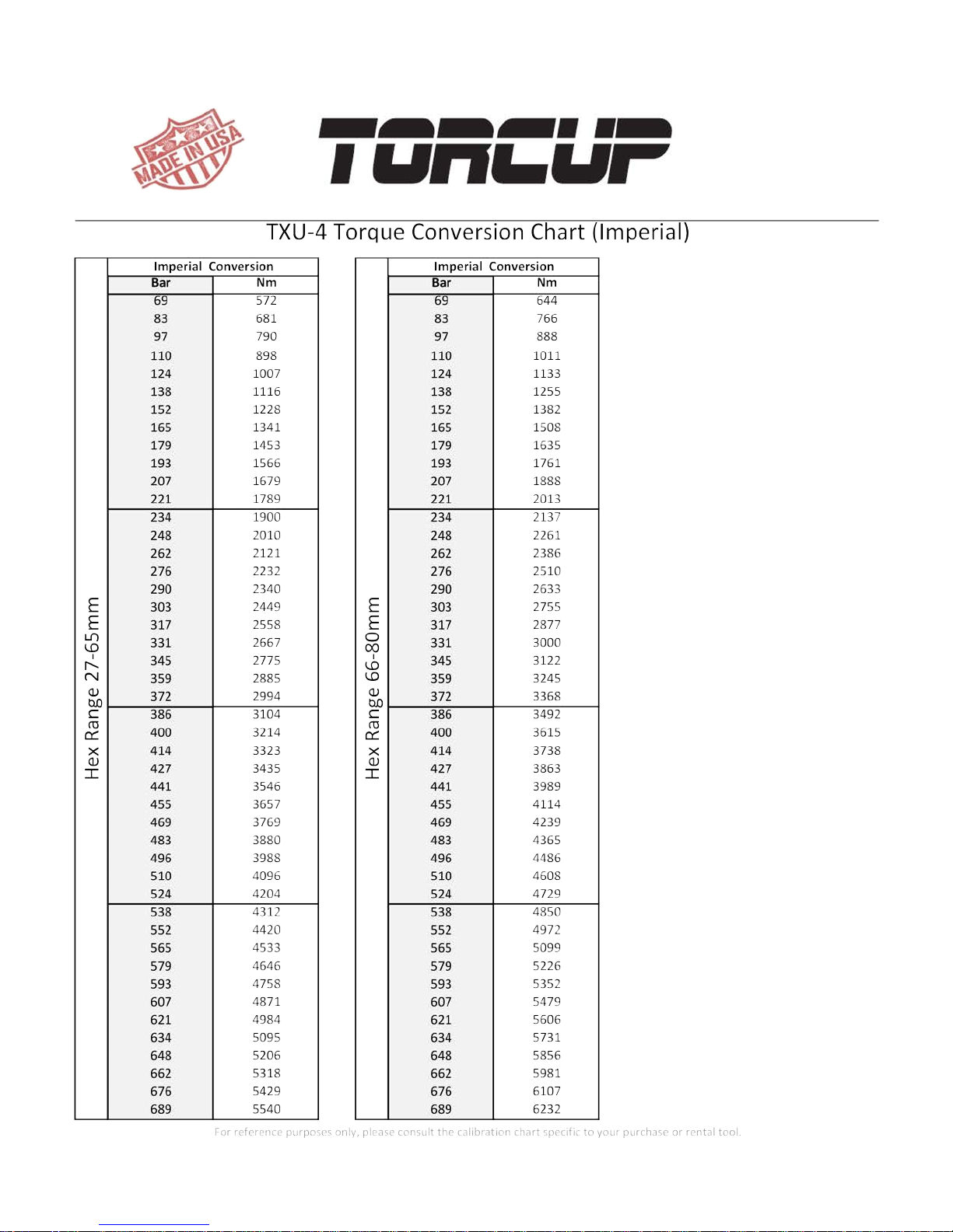
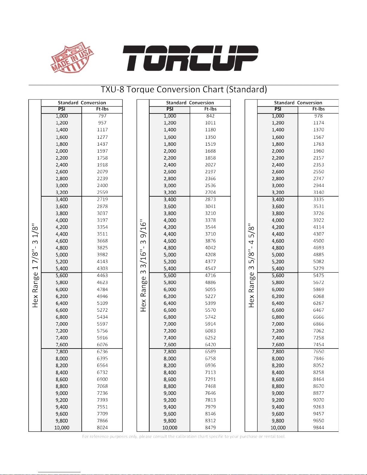
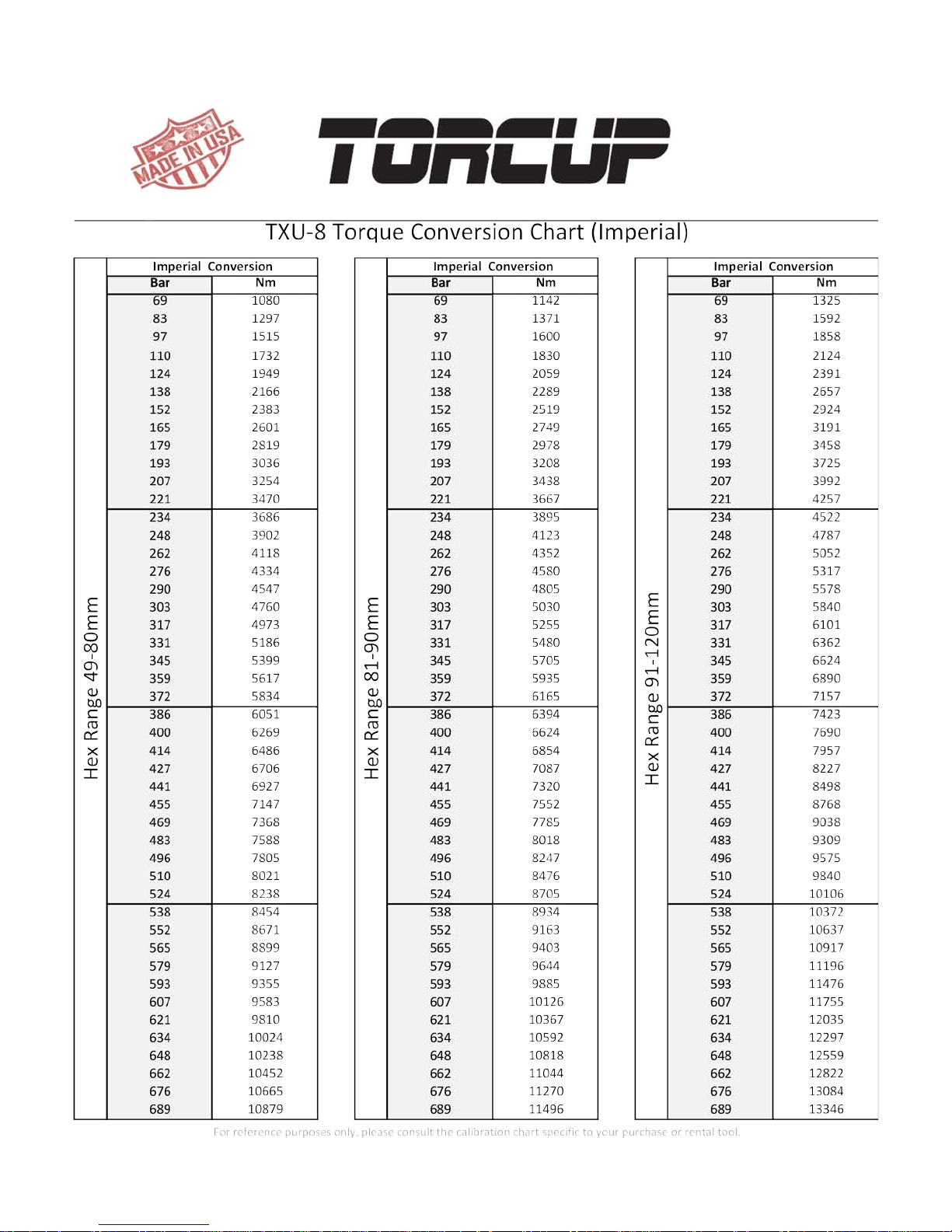
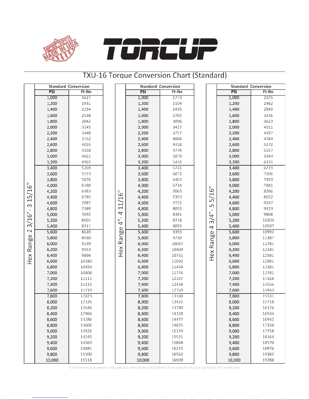
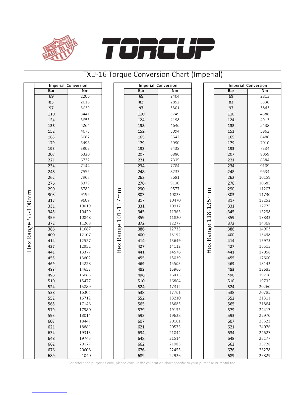
After determining the desired torque, use the torque conversion charts on pages 6 to 13 to determine the
pressure that is necessary to achieve that torque.
1. Connect the tool to the power supply and turn the pump on.
2. Depress the remote control button causing the pressure to be shown on the gauge.
3. Adjust the pressure by loosening the wing nut that locks the pressure adjustment thumbscrew.Rotate
the thumbscrew clockwise to increase the pressure and counterclockwise to decrease the pressure.
When decreasing pressure, always lower the pressure below the desired point and then bring the
gauge back up to the desired pressure.
4. When the desired pressure is reached, retighten the wing nut and cycle the tool again to conrm that
the desired pressure setting has been obtained.
OPERATING THE WRENCH
The position of the tool relative to the nut determines
whether the action will tighten or loosen the nut.
(Refer to Dwg. 2 for application examples). The power
stroke of the piston assembly will always turn the ratchet
hex toward the shroud.
1. Place the ratchet hex on the nut. Make certain it is the
correct size for the nut and that it fully engages the nut.
2. Position the reaction surface against an adjacent
nut, ange or solid system component. Make certain
that there is clearance for the hoses, swivels and inlets.
DO NOT allow the tool to react against the hoses or
swivels.
Wrench Positions Dwg. 2
3
Page 5

PLACING THE TOOL IN SERVICE
3. After having turned the pump on and presetting the pressure for the correct torque, depress
the remote control button to advance the piston assembly. If the notch in the piston rod did not
engage the retract pin in the ratchet link when the link was joined to the housing, it will engage the
pin automatically during the rst advance stroke.
4. When the link is connected to the cylinder and the wrench is started, the reaction surface of the
wrench will move against the contact point and the nut will begin to turn.
5. When the nut is no longer turning and the pump gauge reaches the preset pressure, release the
remote control button. The piston rod will retract when the button is released and under normal
conditions, an audible “click” will be heard as the tool resets itself.
6. Continue to cycle the tool until it “stalls” and the preset psi/torque has been attained.
7. Cycle the tool one additional time to ensure full torque.
LUBRICATION
MARINE MOLY GREASE
Lubrication frequency is dependent on factors known only to the user. The amount of contaminants in
the work area is one factor. Tools used in a clean room environment will obviously require less service
than a tool used out-doors and dropped in loose dirt or sand. Marine Moly Grease is formulated not to
wash out of the tool in areas where lubrication is critical. Whenever lubrication is required, lubricate as
follows:
1. Separate the low prole cylinder from the ratchet link if they are joined.
2. After wiping off the old grease, apply a daub of Marine Moly Grease to the hooking notch in the
piston rod, and wipe a lm of Marine Moly Grease onto the sides and faces of the two sliders.
3. Disassemble the ratchet link as instructed in the Maintenance Section and wash the components
in a suitable cleaning solution in a well ventilated area.
4. Dry the components, then wipe a lm of Marine Moly Grease onto the wear surface of both side
plate sleeves and the hubs of the ratchet.
5. Spread a light lm of Marine Moly Grease onto the inner faces of both side plates, covering the
area where the drive plate and drive segment travel. DO NOT pack the teeth of the drive segment
or ratchet with lube. It can prevent the teeth from engaging properly.
6. Reassemble the ratchet link as instructed in the Maintenance Section.
4
Page 6
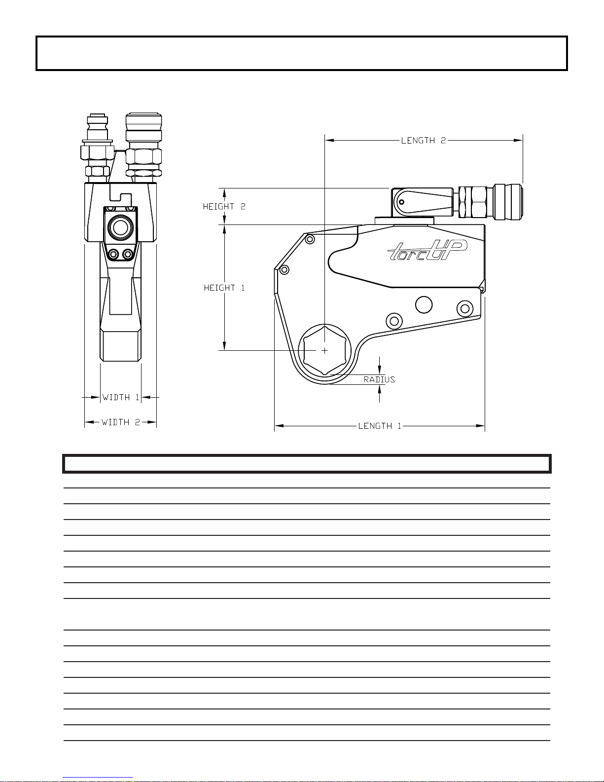
TXU Series Uni-Swivel Wrench Technical & Dimensional Data
Model Number TXU-2 TXU-4 TXU-8 TXU-16
Min. Torque (ft/lbs) 192 395 830 1560
Max. Torque (ft/lbs) 1928 3950 8630 16600
Min. Torque (nm) 260 535 1125 2115
Max. Torque (nm) 2614 5355 11699 22503
Output Accuracy +/-3% +/-3% +/-3% +/-3%
Repeatability 100% 100% 100% 100%
Duty Cycle 100% 100% 100% 100%
Cylinder Weight (lbs/kg) 4.0/1.8 6.9/3.1 12.5/5.7 16/7.3
Link Weight
Length 1 (in/mm) 6.45/163.8 7.87/199.9 10.81/258.6 12.93/328.4
Length 2 (in/mm) 5.99/152.4 6.58/167.1 7.34/186.4 8.20/208.2
Width 1 (in/mm) 1.25/31.8 1.63/41.4 2.05/52.1 2.50/63.5
Width 2 (in/mm) 2.19/55.6 2.26/57.4 2.26/57.4 2.26/57.4
Radius (in/mm) 0.36/9.1 0.46/11.7 0.54/13.7 0.65/16.5
Height 1 (in/mm) 3.39/86.3 4.93/125.2 6.18/157 7.58/192.5
Height 2 (in/mm) 1.11/28.2 1.30/33.0 1.30/33.0 1.30/33.0
(lbs) 2.4-3.5 5.4-7.6 11.9-14.5 21.0-28.0
(kg) 1.0-1.5 2.4-3.4 5.5-6.5 9.5-13.0
5
Page 7
6
Page 8
7
Page 9
8
Page 10
9
Page 11
10
Page 12
11
Page 13
12
Page 14
13
Page 15
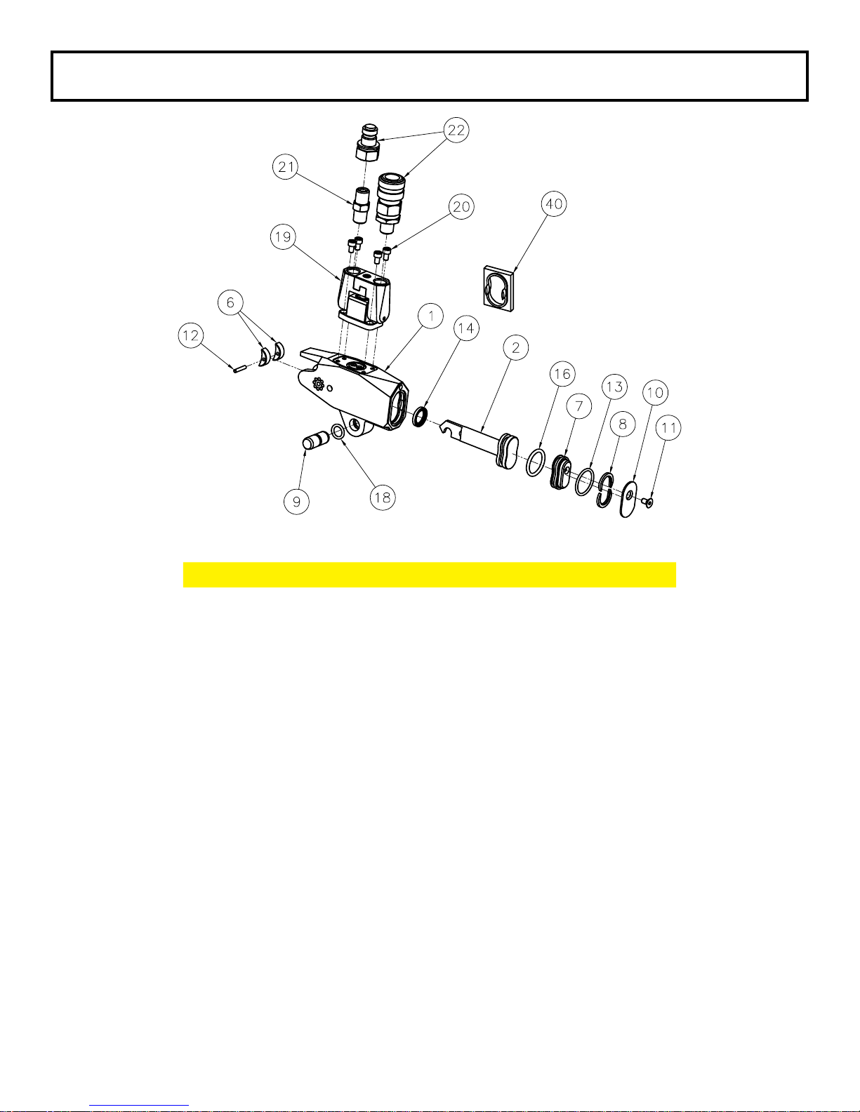
TXU-2 Cylinder Swivel Low Prole Hydraulic Torque Wrench
Part Numbers for Ordering
ITEM NAME PART # QTY.
1 Housing TXU-2-C01 1
2 Piston TX-2-C03 1
6 Slider TX-2-C09 2
7 End Cap TXU-2-C11 1
8 Retaining Ring TX-2-C13 2
9 Link Pin TX-2-C15 1
10 End Cover TXU-2-C17 1
11 End Cover Screw TX-2-C23 1
12 Slider Pin TX-2-C27 1
13 End Plug Seal TX-2-C29 1
14 Rod Seal TX-2-C31 1
16 Piston Seal TX-2-C33 1
18 Link Retaining Spring TX-2-C53 1
19 Uniswivel Assembly USS-00 1
20 Uniswivel Post Screw USS-21 4
21 Male 1/4” NPT to Male 1/4” NPT F004004 1
22 Coupler Set HC-S-100 1
40 Seal Insertion Tool ATX-2-ST
14
Page 16
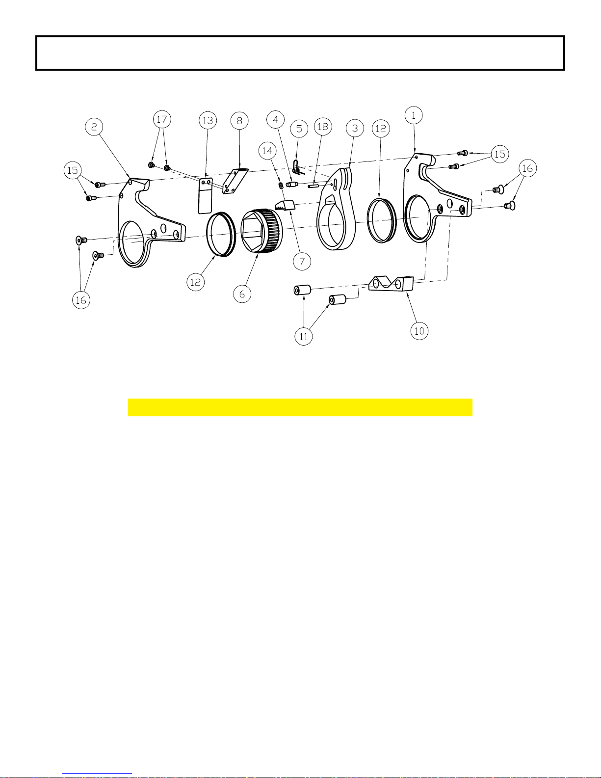
TXU-2 Series Link
Part Numbers for Ordering
ITEM NAME PART # QTY.
1 Side Plate - Left TX-2-L01 1
2 Side Plate - Right TX-2-L02 1
3 Drive Plate TX-2-L03 1
4 Drive Pin TX-2-L05 1
5 Drive Pin Spring TX-2-L07 1
6 Ratchet TX-2-L09 1
7 Drive Segment TX-2-L11 1
8 Upper Spacer TX-2-L13 1
10 Lower Spacer TX-2-L15 1
11 Spacer Pin TX-2-L17 2
12 Sideplate Sleeve TX-2-L19 2
13 Shroud TX-2-L21 1
14 Segment Spring TX-2-L25 1
15 Upper Spacer Screw TX-2-L27 4
16 Lower Spacer Screw TX-2-L29 4
17 Shroud Screw TX-2-L31 2
18 Drive Pin Spring Roll Pin TX-2-L33 1
15
Page 17
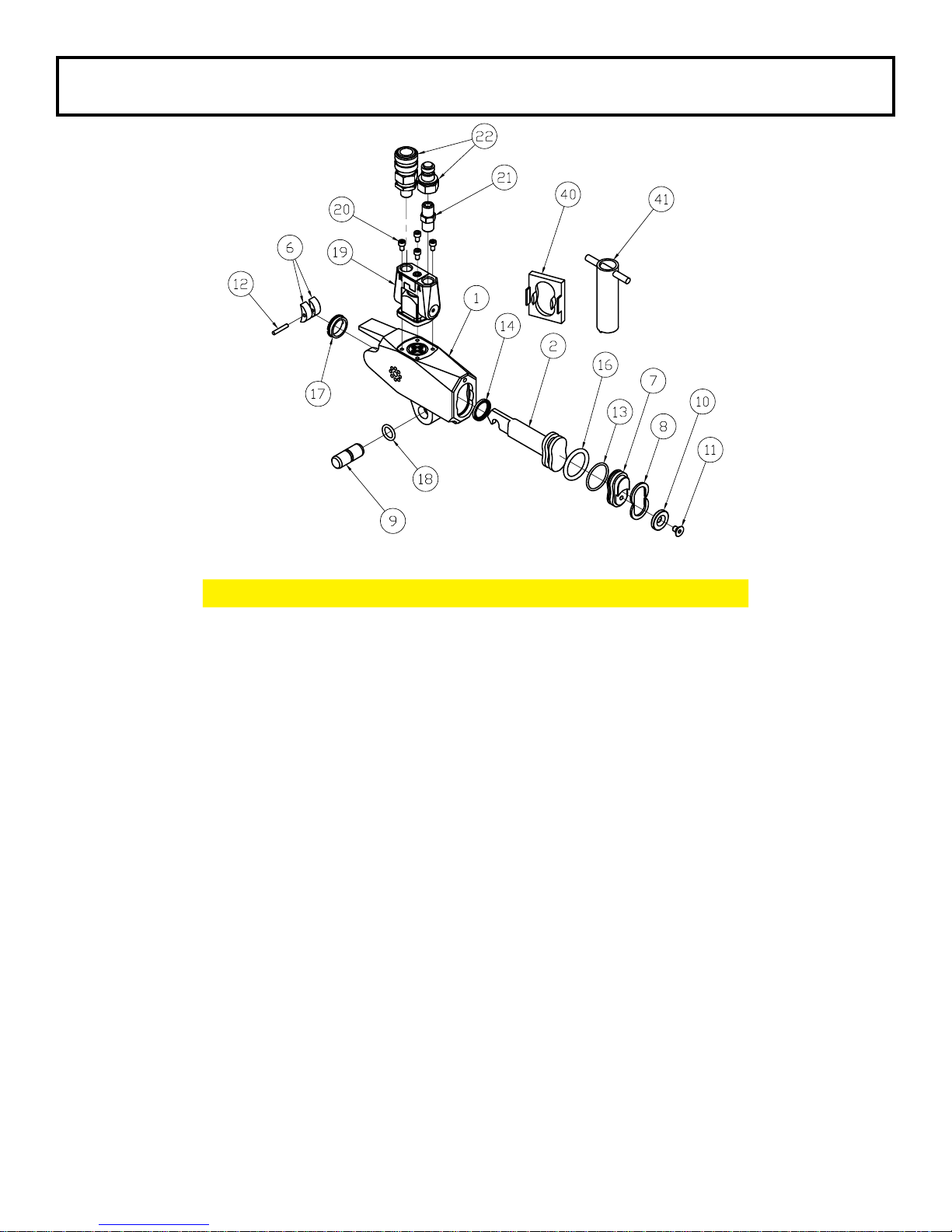
TXU-4 Cylinder Swivel Low Prole Hydraulic Torque Wrench
Part Numbers for Ordering
ITEM NAME PART # QTY.
1 Housing TXU-4-C01 1
2 Piston TX-4-C03 1
6 Slider TX-4-C09 2
7 End Cap TXU-4-C11 1
8 Retaining Ring TX-4-C13 2
9 Link Pin TX-4-C15 1
10 End Cover TXU-4-C17 1
11 End Cover Screw TX-4-C23 1
12 Slider Pin TX-4-C27 1
13 End Plug Seal TX-4-C29 1
14 Rod Seal TX-4-C31 1
16 Piston Seal TX-4-C33 1
17 Cylinder Gland TX-4-C51 1
18 Link Retaining Spring TX-4-C53 1
19 Uniswivel Assembly USL-00 1
20 Uniswivel Post Screw USL-21 4
21 Male 1/4” NPT to Male 1/4” NPT F004004 1
22 Coupler Set HC-S-100 1
40 Seal Insertion Tool ATX-4-ST
41 Gland Removal Tool ATX-4-GW
16
Page 18
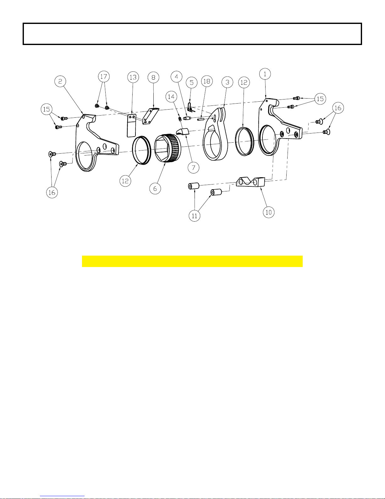
TXU-4 Series Link
Part Numbers for Ordering
ITEM NAME PART # QTY.
1 Side Plate - Left TX-4-L01 1
2 Side Plate - Right TX-4-L02 1
3 Drive Plate TX-4-L03 1
4 Drive Pin TX-4-L05 1
5 Drive Pin Spring TX-4-L07 1
6 Ratchet TX-4-L09 1
7 Drive Segment TX-4-L11 1
8 Upper Spacer TX-4-L13 1
10 Lower Spacer TX-4-L15 1
11 Spacer Pin TX-4-L17 2
12 Sideplate Sleeve TX-4-L19 2
13 Shroud TX-4-L21 1
14 Segment Spring TX-4-L25 1
15 Upper Spacer Screw TX-4-L27 4
16 Lower Spacer Screw TX-4-L29 4
17 Shroud Screw TX-4-L31 2
18 Drive Pin Spring Roll Pin TX-4-L33 1
17
Page 19
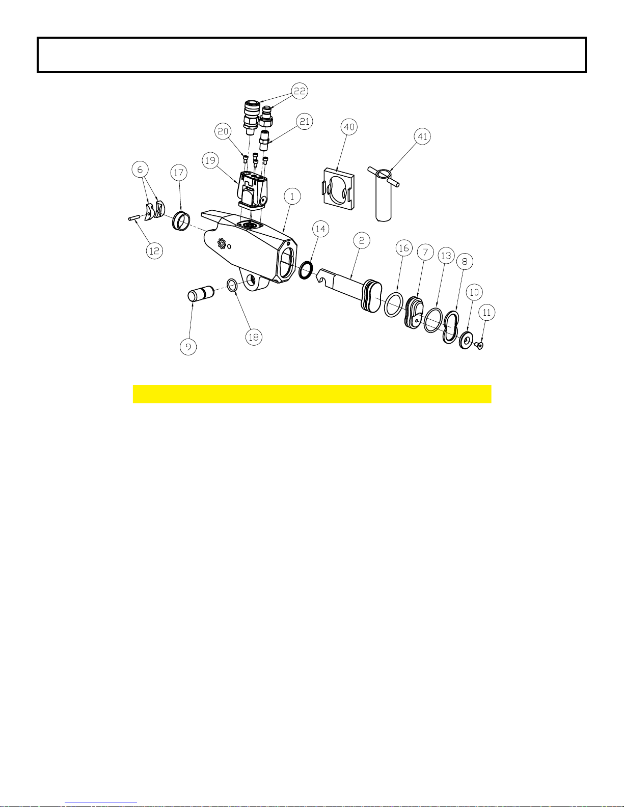
TXU-8 Cylinder Swivel Low Prole Hydraulic Torque Wrench
Part Numbers for Ordering
ITEM NAME PART # QTY.
1 Housing TXU-8-C01 1
2 Piston TX-8-C03 1
6 Slider TX-8-C09 2
7 End Cap TXU-8-C11 1
8 Retaining Ring TX-8-C13 2
9 Link Pin TX-8-C15 1
10 End Cover TXU-8-C17 1
11 End Cover Screw TX-8-C23 1
12 Slider Pin TX-8-C27 1
13 End Plug Seal TX-8-C29 1
14 Rod Seal TX-8-C31 1
16 Piston Seal TX-8-C33 1
17 Cylinder Gland TX-8-C51 1
18 Link Retaining Spring TX-8-C53 1
19 Uniswivel Assembly USL-00 1
20 Uniswivel Post Screw USL-21 4
21 Male 1/4” NPT to Male 1/4” NPT F004004 1
22 Coupler Set HC-S-100 1
40 Seal Insertion Tool ATX-8-ST
41 Gland Removal Tool ATX-8-GW
18
Page 20
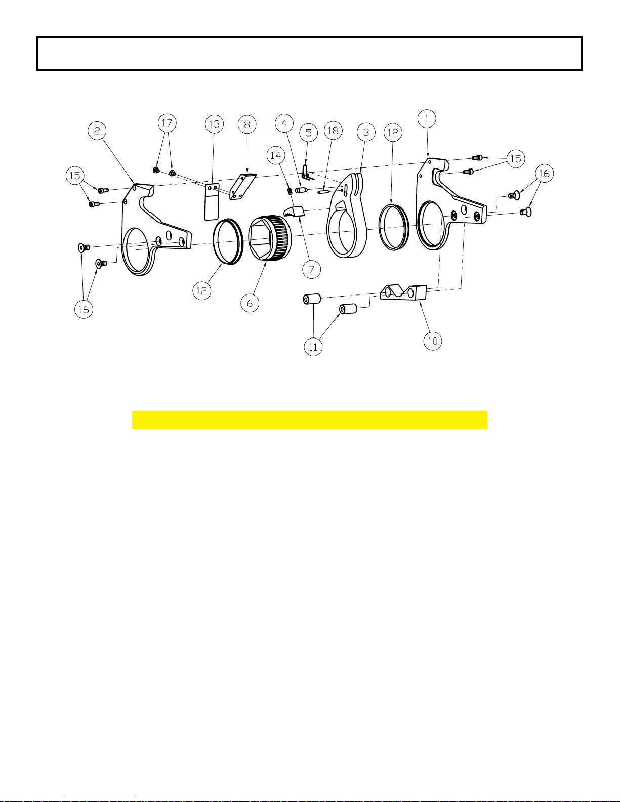
TXU-8 Series Link
Part Numbers for Ordering
ITEM NAME PART # QTY.
1 Side Plate - Left TX-8-L01 1
2 Side Plate - Right TX-8-L02 1
3 Drive Plate TX-8-L03 1
4 Drive Pin TX-8-L05 1
5 Drive Pin Spring TX-8-L07 1
6 Ratchet TX-8-L09 1
7 Drive Segment TX-8-L11 1
8 Upper Spacer TX-8-L13 1
10 Lower Spacer TX-8-L15 1
11 Spacer Pin TX-8-L17 2
12 Sideplate Sleeve TX-8-L19 2
13 Shroud TX-8-L21 1
14 Segment Spring TX-8-L25 1
15 Upper Spacer Screw TX-8-L27 4
16 Lower Spacer Screw TX-8-L29 4
17 Shroud Screw TX-8-L31 2
18 Drive Pin Spring Roll Pin TX-8-L33 1
19
Page 21
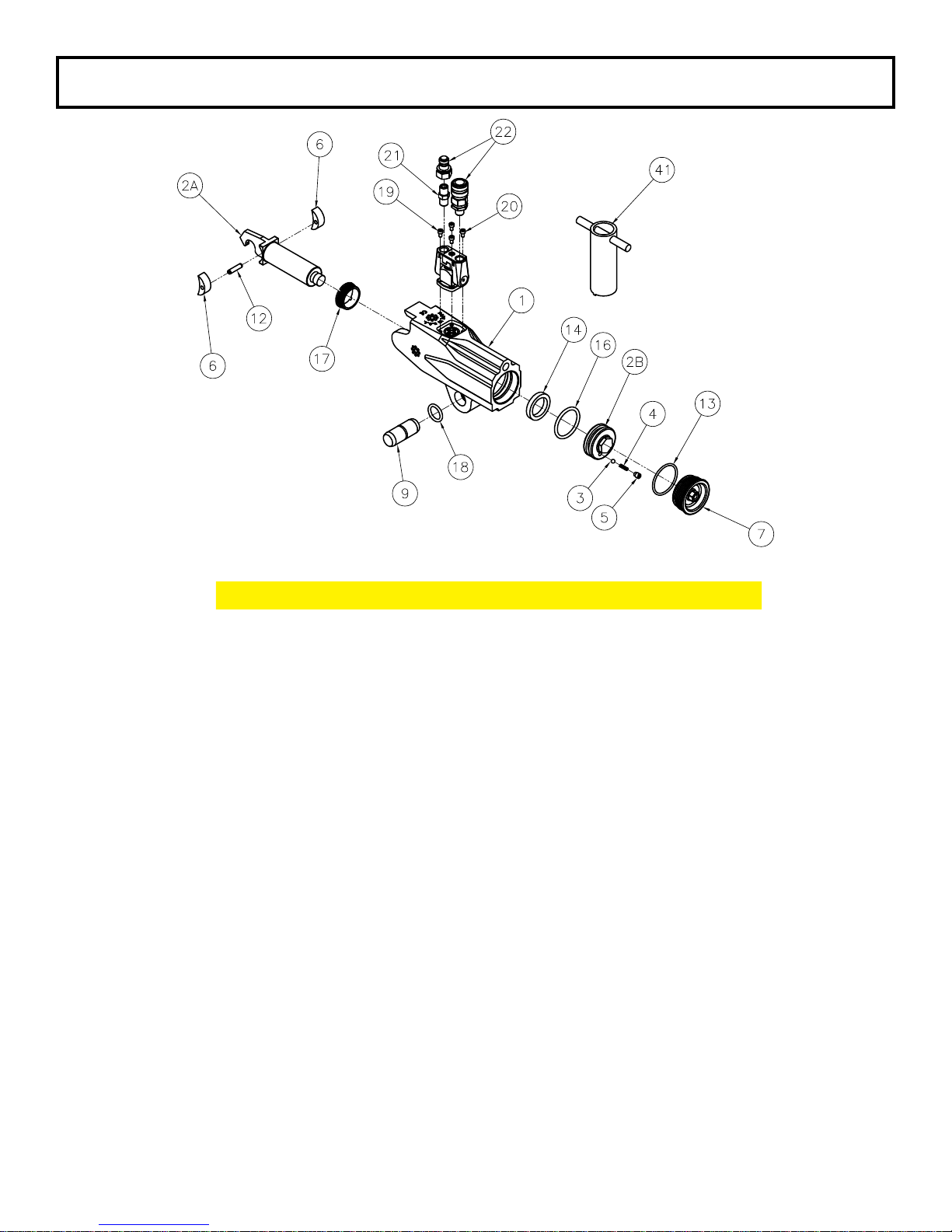
TXU-16 Cylinder Swivel Low Prole Hydraulic Torque Wrench
Part Numbers for Ordering
ITEM NAME PART # QTY.
1 Housing TXU-16-C01 1
2A Piston Rod TX-16-C03-1 1
2B Piston Cap TX-16-C03-2 1
3 Valve Ball TX-16-C03-3 1
4 Valve Spring TX-16-C03-4 1
5 Valve Cup TX-16-C03-5 1
6 Slider TX-16-C09 2
7 End Cap TXU-16-C11 1
9 Link Pin TX-16-C15 1
12 Slider Pin TX-16-C27 1
13 End Plug Seal TX-16-C29 1
14 Rod Seal TX-16-C31 1
16 Piston Seal TX-16-C33 1
17 Cylinder Gland TX-16-C51 1
18 Link Retaining Spring TX-16-C53 1
19 Uniswivel Assembly USL-00 1
20 Uniswivel Post Screw USL-21 4
21 Male 1/4” NPT to Male 1/4” NPT F004004 1
22 Coupler Set HC-S-100 1
41 Gland Removal Tool ATX-16-GW
42 End Plug Wrench ATX-16-EPW
Piston Assembly TX-16-03
20
Page 22
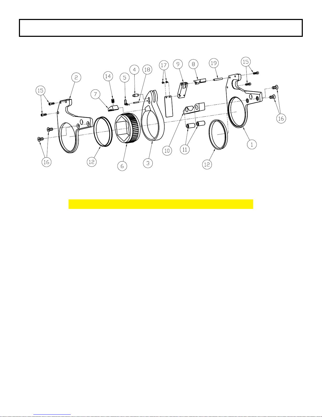
TXU-16 Series Link
Part Numbers for Ordering
ITEM NAME PART # QTY.
1 Side Plate - Left TX-16-L01 1
2 Side Plate - Right TX-16-L02 1
3 Drive Plate TX-16-L03 1
4 Drive Pin TX-16-L05 1
5 Drive Pin Spring TX-16-L07 1
6 Ratchet TX-16-L09 1
7 Drive Segment TX-16-L11 1
8 Upper Spacer TX-16-L13 1
9 Middle Spacer TX-16-L14 1
10 Lower Spacer TX-16-L15 1
11 Spacer Pin TX-16-L17 2
12 Sideplate Sleeve TX-16-L19 2
13 Shroud TX-16-L21 1
14 Segment Spring TX-16-L25 1
15 Upper Spacer Screw TX-16-L27 4
16 Lower Spacer Screw TX-16-L29 4
17 Shroud Screw TX-16-L31 2
18 Drive Pin Spring Roll Pin TX-16-L33 1
19 Spacer Roll Pin TX-16-L35 1
21
Page 23
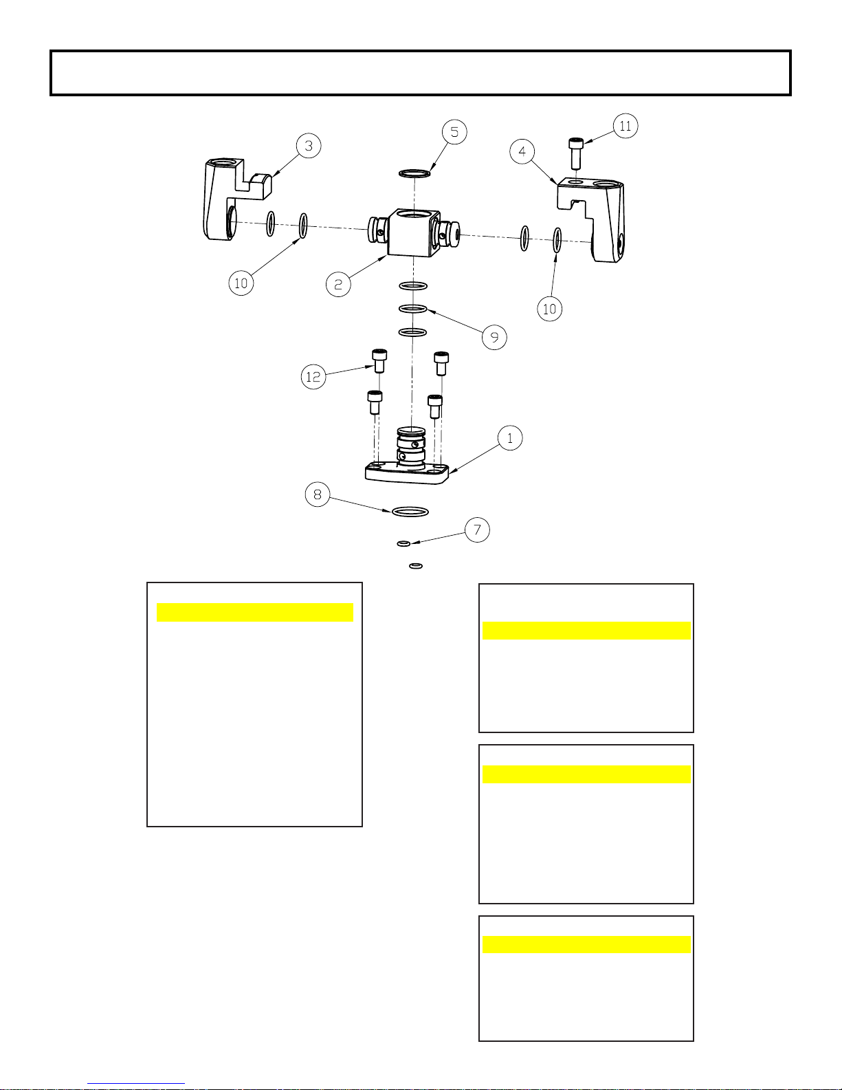
TXU Series USS Uni-swivel
T
7
USSUni‐swivelPartsList
ITEM NAME
1 Post
2 Joint 1 Post
3 SwivelArm(Advance) 7 SwivelO‐ring(Small)
4 SwivelArm(Retract) 8 SwivelO‐ring(Large)
5 RetainingRing 9 PostO‐ring
7 SwivelO‐ring(Small) 12 SwivelPostScrew
8 SwivelO‐ring(Large)
9 PostO‐ring JointKit USS‐JKIT
10 JointO‐ring
11 SwivelScrew 2 Joint
12 SwivelPostScrew 3 SwivelArm(Advance)
Availablerepairkits
PostKit USS‐PKIT
ITEM NAME
ITEM NAME
4 SwivelArm(Retract)
5 RetainingRing
9 PostO‐ring
10 JointO‐ring
11 SwivelScrew
SealKit USS‐SKI
ITEM NAME
SwivelO‐ring(Small)
8 SwivelO‐ring(Large)
9 PostO‐ring
10 JointO‐ring
12 SwivelPostScrew
22
Page 24
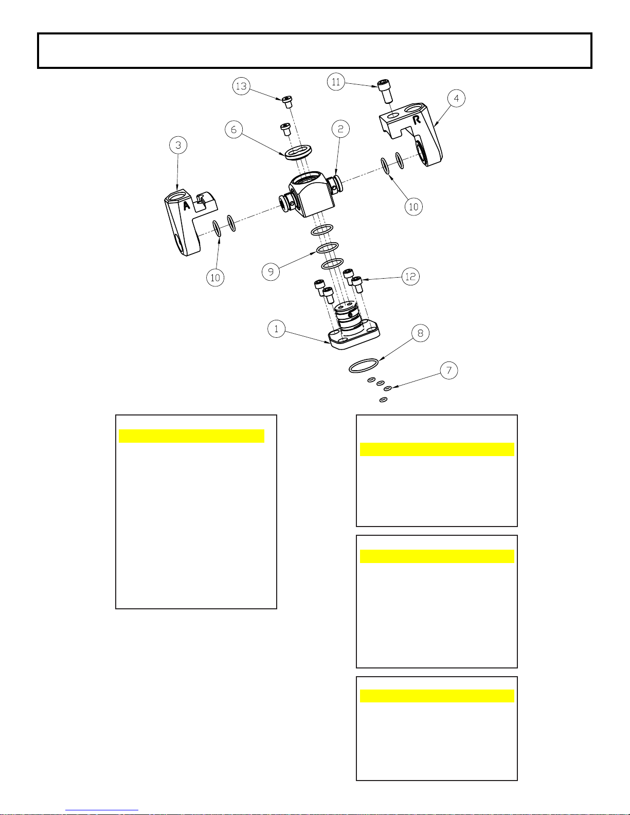
TXU Series USL Uni-swivel
12
SwivelPostScrew
3
SwivelArm(Advance)
13
CapScrew
4
SwivelArm(Retract)
6
Cap9PostO‐ring
10
JointO‐ring
11
SwivelScrew
13
CapScrew
SealKit
USL‐SKIT
ITEM
NAME
7
SwivelO‐ring(Small)
8
SwivelO‐ring(Large)
9
PostO‐ring
10
JointO‐ring
12
SwivelPostScrew
13
CapScrew
USLUni‐swivelPartsList
Availablerepairkits
ITEM NAME
1 Post
2 Joint 1 Post
3 SwivelArm(Advance) 7 SwivelO‐ring(Small)
4 SwivelArm(Retract) 8 SwivelO‐ring(Large)
6 Cap 9 PostO‐ring
7 SwivelO‐ring(Small) 12 SwivelPostScrew
8 SwivelO‐ring(Large)
9 PostO‐ring JointKit USL‐JKIT
10 JointO‐ring
11 SwivelScrew 2 Joint
PostKit USL‐PKIT
ITEM NAME
ITEM NAME
23
Page 25

TXU Series Uni-swivel Assembly
1. Clamp the post (1) in a
2. Slide the post O-rings (9) onto the post starting from the top to the base.
3. Lightly lubricate the post.
4. Using hand pressure, press the joint (2) onto the post until it makes contact with the base of the
post and until the top of the post is ush with the top of the joint.
5. For USS uni-swivels: install the retaining ring (5) into the groove on the top of the post by
spreading it open slightly and working it around the post. For USL uni-swivels: install the cap (6)
and secure with the cap screws (13).
6. Slide the joint O-rings (10) onto the arms of the joint from outside to inside.
7. Lightly lubricate the arms of the joint.
8. Using hand pressure, press the swivels (3 & 4) onto the joint. Note: One of the arms of the joint
has an ‘R’ engraved on the end denoting that it is the retract side. Install the retract swivel (4) onto
this arm.
9. Swing the arms together so they interlock and fasten them together with the swivel screw (11).
10. Install the large and small swivel O-rings (7 & 8) into their glands in the cylinder housing.
11. Install the uni-swivel assembly onto the cylinder housing with the swivel post screws (12).
copper-covered or leather-covered
vice by the base.
24
Page 26
MAINTENANCE SECTION
Always turn off the power supply. Bleed off hydraulic uid from the hose
connections on the cylinder assembly and disconnect the hoses before
WARNING
DISASSEMBLY
GENERAL INSTRUCTIONS
1. Do not disassemble the tool any further than necessary to replace or repair damaged parts.
2. Use extra care not to score, nick or damage surfaces that will contain hydraulic oil under pressure.
3. Whenever grasping a tool in a vise, always use leather–covered or copper–covered vise jaws to
protect the surface of the part and help prevent distortion. This is particularly true of threaded
members and housings.
4. Do not remove any part that is press t in or on an assembly unless the removal of that part is
necessary for repairs or replacement.
5. Do not disassemble the hydraulic cylinder assembly unless you have a complete set of seals and
O–rings for replacement.
6. Use only British Standard fractional size tools when disassembling these tools.
DISASSEMBLY OF THE TOOL
1.
Push the link pin (9) out of the cylinder housing (1) and link side plates (1 & 2).
2.
Lift the housing from between the side plates and separate the two units.
attempting to repair or perform maintenance on this tool. Always wear
eye protection when operating or performing maintenance on this tool.
DISASSEMBLY OF THE TXU-2, TXU-4, AND TXU-8 CYLINDER ASSEMBLIES
1.
Clamp the housing (1) in copper-covered or leather-covered vise jaws with the uniswivel upward.
Using a hex wrench, unscrew the four uniswivel post screws (20) that clamp the uniswivel to the
housing. Collect the O-rings (three for the TXU-2, ve for the TXU-4 and TXU-8).
2.
Remove the housing from the vise and turn it over a container to catch any oil remaining inside the
cylinder.
3. Place the tool with the slider pin hole over a clearance opening and use a small drift to tap the slider
pin (12) out of the sliders (6) and piston (2).
(10) end upward.
4.
Use a hex wrench to unscrew and remove the end cover screw (11). Remove the end cover (10).
5.
Tap the end cap (7) inward approximately 1/2” and remove the two retaining rings (8) by working
them out of the groove in the cylinder. Note: Covering the oil ports with a cloth will contain any oil
that may expel from the housing.
CAUTION
6.
Install the seal insertion tool (40) into the end of the housing (1). Note: Lubricating the inside of the
insertion tool will ease the removal of the piston (2) and end cap (7).
7.
Invert the tool above the vice, spreading the vice open enough to catch the end plug and piston.
Note: Placing a cloth draped between the jaws of the vice will contain the exiting parts.
8.
Tap the piston with a brass tap lightly until both the piston and end cap slip through the housing and
into the catch cloth.
9.
Use the gland removal tool (41) to unscrew and remove the cylinder gland (17) from the housing.
Note: TXU-2 does not have a cylinder gland.
The purpose of the seal insertion tool in the following step is to prevent
the end plug seal from expanding into the retaining ring groove. If the
tool is not used, place two thin pieces of at stock at the midpoint of the
opening against opposite walls to control the seal expansion.
Re-clamp the housing in the vise with the end cover
25
Page 27
MAINTENANCE SECTION
During removal and after the piston shaft is removed; DO NOT grasp
NOTICE
DISASSEMBLY OF THE TXU-16 CYLINDER ASSEMBLIES
1. Clamp the housing (1) in copper-covered or leather-covered vise jaws with the uniswivel upward.
Using a hex wrench, unscrew the four uniswivel post screws (20) that clamp the uniswivel to the
housing. Remove the uniswivel and O-rings.
2. Re-clamp the housing in the vise with the end cap (7) upward.
3. Unscrew the end cap (7) from the housing.
4. Using a socket on the hex of the piston cap (2B), unscrew and remove the piston cap from the
piston rod (2A).
5. Remove the housing from the vise and turn over a container to empty any remaining oil from the
housing.
6. Re-clamp the housing in the vise, end plug end upward.
7. Remove the piston rod (2A) from the housing. If necessary, tap the threaded end of the piston rod
with a brass tap being careful not to damage the threads. Place a cloth between the jaws of the
vice to contain the exiting parts.
8. Flip the housing in the vice so that the cylinder gland (17) is visible.
9. Use the gland removal tool (41) to unscrew the cyclinder gland (17) from the housing.
10. Place the slider pin in the piston rod over a clearance opening in a soft block, and use a small drift
to tap the pin out of the sliders and piston rod.
the round portion of the rod with any holding device that will damage
the surface. Any nicks or scratches to the surface will allow hydraulic
oil to leak from the cylinder when the tool is reassembled.
DISASSEMBLY OF THE RATCHET LINK
1. Lay the ratchet link at on a workbench with the left side plate (1) downward and using a hex
wrench, unscrew and remove the two lower spacer screws (16).
2. Using a hex wrench, unscrew and remove the two upper spacer screws (15).
3. For series TXU-16: Use a roll pin punch to tap the spacer roll pin (19) out of the right side plate (2).
4. While applying thumb pressure to the edge of the ratchet (6), carefully lift the side plate off the
assembly.
5. Grasp the ratchet and drive plate (3) and, while maintaining their relationship, lift them both off the
left side plate.
6. Push the Ratchet out of the drive plate and remove the drive segment (7) and the segment spring
(14) from the drive plate recess.
NOTICE
7. If the drive pin (4) or drive pin spring (5) must be replaced, use a roll pin punch to push the drive pin
spring roll pin (18) out of the drive plate. Once the pin spring is removed, the drive pin (4) will drop
down to the large opening at the bottom of the slot for easy removal.
8. Lift the lower spacer (10) off the lower spacer pins (11). If the pins must be replaced, use a hex
wrench to remove the two lower spacer screws from the right side plate. Pull the pins out of the
holes on the inner face of the right side plate.
When the ratchet is removed from the drive plate, the drive segment
and segment spring will be free to fall from the drive plate recess. Do
not allow the drive segment to fall on a hard surface that might chip the
teeth.
26
Page 28

MAINTENANCE SECTION
9. For Series TXU-2, TXU-4, and TXU-8 models: Unscrew the two spacer screws and remove the
upper spacer (8) from the right side plate. For Series TXU-16 models: Use a roll pin punch to
remove the spacer roll pin (19) from the right side plate. Unscrew the two spacer screws and
remove the middle spacer (9) and upper spacer (8) from the right side plate.
10. If the side plate sleeves (12) must be replaced, press the sleeves out toward the inner face of the
side plate.
NOTICE
Inspect all parts prior to assembly. Replace any worn or damaged parts.
ASSEMBLY
ASSEMBLY OF THE TXU-2, TXU-4 & TXU-8 CYLINDER ASSEMBLIES
1. Clamp the housing (1) in copper-covered or leather-covered vise jaws with the end cap end
downward.
2. Apply a non-permanent thread-locking compound to the threads of the cylinder gland (17). Use
the gland removal tool (41) to thread the bushing into the small central opening in the housing and
tighten until ush with the housing (1). Note: TXU-2 does not have a cylinder gland.
3. Flip the housing (1) in the vise and install the seal insertion tool (40). Note: Lubricating the inside of
the insertion tool and the sides of the piston rod assembly and end cap will ease installation.
4. Insert the piston (2) into the seal insertion tool (41), notched end leading and toward the link pin
hub, and tap into housing approximately 1”.
5. Insert the end cap (7), swivel inlet toward the link pin hub, into the seal insertion tool (40), and tap in
until the piston (2) bottoms out against the housing (1).
6. Install retaining rings (8), tapered edge leading into the grooves in the housing.
7. Flip the housing in the vise and drive the piston (2) into the housing with a brass tap until the end
cap (7) seats in the retaining rings (8).
8. Install the end cover (10), applying a non-permanent thread-locking compound to the end cover
screw (11) threads.
9. Remove the housing from the vice and place on a soft block with the engraved side up.
10. Install sliders (6), one on each side of the piston (2). For TX-8 models: Install sliders with the
cutout towards the piston. Align the holes in the sliders with the holes in the piston and the housing.
11. Install slider pin (12) until ush with top slider.
12. Apply moly grease to the face of the sliders and the notch in the piston.
13. Apply non-permanent, thread-locking compound to the threads of the cylinder, and install uniswivel
O-rings and uniswivel (USS for TXU-2 or USL for TXU-4 & 8), tightening uniswivel post screws (20)
in a cross pattern.
ASSEMBLY OF TXU-16 CYLINDER ASSEMBLIES
1. Press the slider pin (12) into one of the sliders (6) until ush with one side. Install the pin through
the hole in the piston rod (2A) and press the remaining slider into the pin.
2. Clamp the housing (1) in copper-covered or leather-covered vise jaws with the end cap end
downward.
3. Apply a non-permanent, thread-locking compound to the threads of the cylinder gland (17). Use the
gland removal tool (41) to thread the gland into the small central opening in the housing and tighten
until ush with the housing (1).
4. Insert the piston rod (2A), threaded end leading, into the small cylinder gland in the housing. The
notch in the trailing end of the rod should be towards the retaining pin hub.
5. Insert the piston cap (2B), hex end trailing, into the bore of the housing and use a socket to thread
and tighten the piston cap onto the piston rod.
27
Page 29
MAINTENANCE SECTION
6. Using a socket, thread the end cap (7), O-ring leading, into the bore of the housing and tighten.
7. Install uniswivel O-rings and uniswivel (USS for TXU-2 or USL for TXU-4 & TXU-8), tightening
uniswivel post screws (20) in a cross pattern. Apply non-permanent, thread-locking compound to
the threads.
8. Apply moly grease to the face of the sliders and the notch in the piston.
ASSEMBLY OF THE RATCHET LINK
1. If the side plate sleeves (12) were removed, press new sleeves, shoulder end trailing, into the right
and left side plates (1 & 2) from the inner face of the side plates. Make certain the sleeves are
square with the side plate faces and the shoulder of the sleeves enters the recesses in the side
plates and are pressed ush with the faces.
2. For Series TXU-2, TXU-4, and TXU-8 models: Position the upper spacer (8) against the inside
face of the right side plate. Apply a non-permanent thread-locking compound to the threads of the
two upper spacer screws (15) and secure the spacer with the screws through the side plate. For
Series TXU-16 models: Press the spacer roll pin (19) into the right side plate with one end of the
pin ush with the external face of the side plate. Insert the tab of the upper spacer (8) into the slot
in the middle spacer (9), and after aligning the holes in both pieces, install them on the spacer roll
pin (19). When they are correctly positioned, apply a non-permanent thread-locking compound to
the threads of the two upper spacer screws (15) and secure the spacers with the screws through
the side plate.
3. Insert the two lower spacer pins (11) into the holes in the lower edge of the right side plate. Apply a
non-permanent thread-locking compound to the threads of the lower spacer screws (16) and secure
the pins with the screws through the side plate.
4. Place the lower spacer (10) over the pins against the side plate. Make certain it is correctly oriented
so that no part of the spacer extends beyond the edge of the side plate.
5. Insert the drive pin (4) into the small cross-hole and slot in the drive plate (3). Invert the plate
causing the ends of the pin to enter the slot and move the pin to the narrow end.
6. Position the drive pin spring (5) in the drive plate slot with the two non-connected ends between the
drive pin and the large hole in the slot. Position the closed end of the spring on the opposite side
of the pin. Then, apply pressure on the spring to align the hole through it with the hole in the drive
plate for the drive pin spring roll pin (18). Insert the spring roll pin into the drive plate, through the
spring and into the far wall of the drive plate.
NOTICE
In the following step, an excessive amount of grease will prevent
proper tooth engagement between the ratchet and the drive
segment, causing the tool to malfunction.
7. Wipe a thin lm of Marine Moly Grease onto the inner face of the large opening in the drive plate.
8. Position the ratchet (6) in the central opening of the drive plate.
9. Insert the drive segment (7) into the opening adjacent to the ratchet. Make certain the teeth of
the ratchet correctly engage the teeth of the drive segment. Reverse the ratchet if they do not
properly engage.
10. Slide the drive segment sideways to expose the spring hole. Install the segment spring (14) into the
hole. While compressing the spring, slide the drive segment inward until the drive plate captures
the segment spring.
11. Apply a light coat of Marine Moly Grease to both sides of the drive plate and drive segment as well
as the inner faces of both side plate sleeves (12).
12. While keeping the assembly together, insert the hub of the ratchet into the side plate sleeve of the
assembled side plate.
28
Page 30

MAINTENANCE SECTION
13. Place the left side plate sleeve on the hub of the ratchet and align the screw holes for the spacers.
14. After applying a non-permanent, thread-locking compound to the threads. Use hex wrenches to
install the two remaining lower spacer screws.
ASSEMBLY OF THE TOOL
1. With the cylinder assembly in one hand and the ratchet link in the other, hook the notch on the
shaft of the cylinder piston rod (2) onto the link drive pin (4) and bring the two assemblies together.
2. Insert the link pin (9) into the hole in the link side plate (1 or 2) until the cylinder piston rod (2) snaps
into the annular groove around the center of the link pin.
29
Page 31
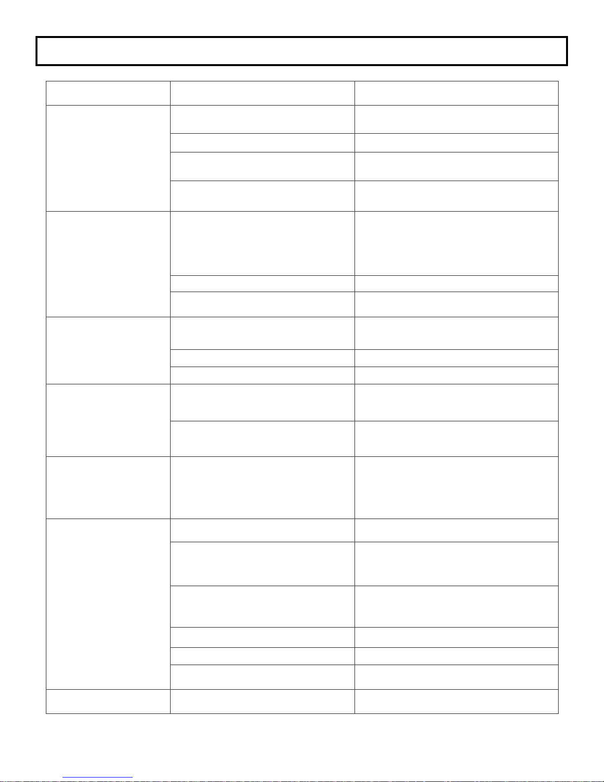
TROUBLESHOOTING GUIDE
Trouble Probable Cause Solution
Piston will not advance
or retract
Piston will not retract
Cylinder will not build
up pressure
Ratchet will not turn
Couplers are not securely attached
to the tool or pump
Coupler is defective Replace any defective coupler.
Defective remote control switch
Dirt in the direction-control valve of
the pump unit
Hose connections reversed
Retract hose not connected Connect the retract hose securely.
Retract pin and/or spring broken Replace the broken pin and/or spring.
Internal seal leaking/or end plug
seal leaking
Retaining screws sheared Replace any broken screws.
Coupler is defective Replace any defective coupler.
Grease or dirt build up in the teeth
of the ratchet link
and drive segment
Worn or broken teeth on ratchet
and/or drive segment
Check the coupler connections and
make certain that they are connected.
Replace the switch and/
or control pendent.
Disassemble the pump and clean the
direction-control valve.
Make certain the advance on the pump
is connected to the advance on the tool
and retract on the pump is connected to
the retract on the tool.
Replace any defective o-rings.
Disassemble the ratchet and clean the
grease or dirt out of the teeth.
Replace any worn or damaged parts.
Tool tightens immedi-
ately when turned on
Pump will not build up
pressure
Pressure reading
erratic
Hose connections are reversed
Defective relief valve
Air supply too low or air hose too
small
Electric power source is too low
Defective gauge Replace the gauge.
Low oil level Check and ll the pump reservoir.
Clogged lter
Defective gauge Replace the gauge.
Depress the advance button to release
the tool; shut the pump off in the
advance position and reverse
the hose connection.
Inspect, adjust or replace
the relief valve.
Make certain the air supply and hose
size comply with the pump manual
recommendations.
Make certain the amperage, voltage
and any extension cord size comply
with the pump manual requirements.
Inspect, clean and/or replace
the pump lter.
30
Page 32

SAVE THESE INSTRUCTIONS DO NOT DESTROY
NOTES:
1025 Conroy Place, Easton, PA. 18040 U.S.A.
Phone: +1 610-250-5800
Fax:+1 610-250-2700
Toll Free: 1-888-TORCUP-1
Email: [email protected]
Website: www.torcup.com
 Loading...