

TorcUP TX-2, TX-32, TX-8, TX-4, TX-16 Operating And Maintenance Instructions Manual
...
TX Series
1025 Conroy Place, Easton PA 18040
Phone: 610-250-5800 * Fax: 610-250-2700
Toll-Free: 1-888-TORCUP-1
E-mail: sales@torcup.com * Website: www.torcup.com

Version 1-2009
2/20
August 2009
OPERATION AND MAINTENANCE MANUAL
FOR TorcUP TX-2, TX-4, TX-8, TX-16, TX-32 and TX-45
LOW PROFILE HYDRAULIC TORQUE WRENCHES
Series TX-2, TX-4, TX-8, TX-16, TX-32 and TX-45 Low Profile Hydraulic Torque Wrenches are designed
for installing and removing large bolts having minimal wrench clearance at offshore platforms, power
plants, steel erection sites and other locations requiring precise high torque during bolt makeup and
maximum torque for bolt breakdown.
TorcUP Inc. is not responsible for customer modification of tools for applications on which TorcUP Inc.
was not consulted.
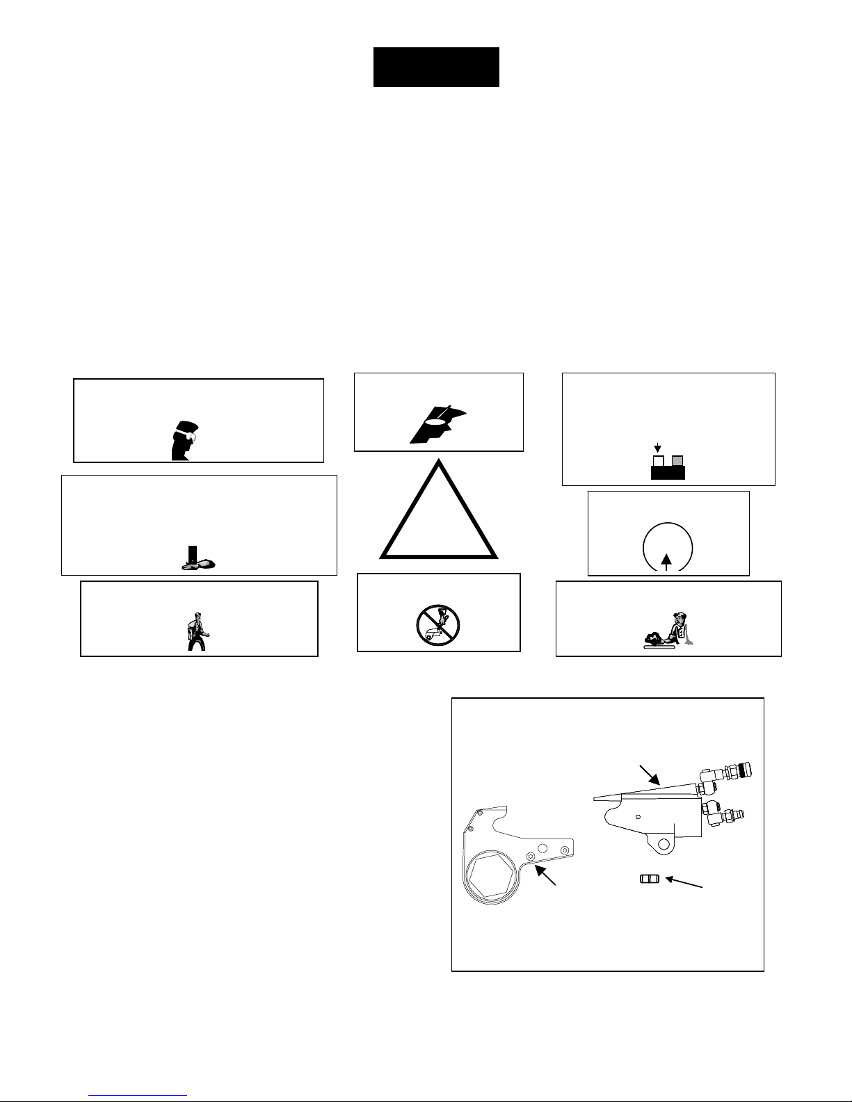
IMPORTANT SAFETY INFORMATION ENCLOSED.
READ THIS MANUAL BEFORE OPERATING TOOL.
IT IS THE RESPONSIBILITY OF THE EMPLOYER TO PLACE THE INFORMATION IN THIS
MANUAL INTO THE HANDS OF THE OPERATOR.
FAILURE TO OBSERVE THE FOLLOWING WARNINGS COULD RESULT IN INJURY
PLACING TOOL IN SERVICE
• Always operate, inspect and maintain this tool in
accordance with American National Standards Safety
Code for Hydraulic Rams and Jacks (ANSI B30.1)
• This tool will function using an air or electric powered
hydraulic pump. Adhere to the pump safety
requirements and follow instructions when connecting
the pump to the tool.
• Use only equipment rated for the same pressure and
torque.
• Use only a hydraulic pump capable of gene r a ti ng
10,000 psig (681 bar) maximum pressure with this tool.
• Use only twin line hydraulic hose rated for 10,00 0 psig
(681 bar) pressure with this tool.
• Do not interchange the male and female swivel inlets
on the tool or the connections on one end of the hose.
Reversing the inlets will reverse the power stroke cycle
and may damage the tool.
• Do not use damaged, frayed or deteriorated hos es a nd
fittings. Make certain there are no cracks, splits or
leaks in the hoses.
The use of other than genuine TorcUP replacement parts may result in safety hazards, decreased tool performance,
and increased maintenance, and may invalidate all warranties.
Repairs should be made only by authorized personnel. Consult your nearest TorcUP Authorized Service Center.
Refer All Communications to the Nearest TorcUP Office or Distributor.
TorcUP Inc. 2000
Printed in U.S.A.
NOTICE
WARNING
.
• Use the quick connect system to attach the hoses to the
tool and pump. Make certain the spring-loaded retaining
rings are fully engaged and the safety rings are tightly
threaded against the spring-loaded retaining rings to
prevent the connectors from disengaging under pressure.
• When connecting hoses that have not been preloaded
with hydraulic oil, make certain the pump reservoir is
not drained of oil during start-up.
• Do not remove any labels. Replace any damaged labels.
USING THE TOOL
• Do not handle pressurized hoses. Escaping oil under
pressure can penetrate the skin, causing serious injury. If
oil is injected under the skin, see a doctor immediately.
• Never pressurize uncoupled couplers. Only use
hydraulic equipment in a coupled system.
• Always wear eye protection when operating or
performing maintenance on this tool.
• Always wear head and hand protection and protective
clothing when operating this tool.
NOTICE
For Technical Support and Information Contact:
TorcUP, Inc.
1025 Conroy Place, Easton, PA 18040
Toll Free: (888) TORCUP-1 Fax: (610) 250-2700
E-mail: info@torcup.com
- -
WARNING
3/20
FAILURE TO OBSERVE THE FOLLOWING WARNINGS COULD RESULT IN INJURY
USING THE TOOL
• Keep hands, loose clothing and long hair away
from the reaction arm and working area during
operation. Do not attempt to support the tool with
your hands during operation.
• This tool will exert a strong reaction force. Use
proper mechanical support and correct reaction arm
positioning to control these forces. Do not position
the reaction arm so that it tilts the tool off the axis of
the bolt and never use the swivel inlets as a reaction
stop.
• Avoid sharp bends and kinks that will cause severe
back-up pressure in hoses and lead to premature hose
• Use accessories recommended by TorcUP.
• Use only impact sockets and accessories. Do not use
hand (chrome) sockets or accessories.
• Use only sockes and accesssories that correctly fit
the bolt or nut and function without tilting the tool
off the axis of the bolt.
• This tool is not designed for working in explosive
atmospheres
• This tool is not insulated against electric shock.
When using this tool with a pump having an
electrical power source or circuits, follow the pump
instructions for proper grounding
.
failure.
Always wear eye protection when operating
Always wear eye protection when operating
or pe rfor ming mainten a nc e on th is to ol.
or pe rfor ming mainten a nc e on th is to ol.
The Torque Reaction Arm must be positioned
against a positive stop. Do not use the Arm as a dead
handle. Take all precautions to make certain the
operator’s hand cannot be pinched between the Arm
and a solid object.
Always wear ear protection
when operating this tool.
!
Always turn off the pump and
disconnect the power before installing,
removing, or adjusting any accessory on
this tool, or before performing any
maintenance on this tool.
ON
ON
OFF
OFF
POWER
POWER
Operate at 10,000 psig
(681bar) maximum pressure.
10,000 psig
10,000 psig
(681 bar)
(681 bar)
Keep body stance balanced and firm. Do not
overreach when operating this tool.
Do not carry the tool by the
hose.
Do not use damaged, frayed or
deteriorated hydraulic hoses and fittings.
PLACING THE TOOL IN SERVICE
CONNECTING THE TOOL
1. Attach the twin line hose to the swivel inlets of the
Low Profile Driver Assembly using the spring–loaded quick
connect ends. After making certain that they are fully engaged,
thread the safety rings tightly against the spring–loaded
retainer rings.
2. Connect the opposite ends of the hose to the Pump in the
same manner.
3. Push the Link Retaining Pin out of the Low Profile Drive
Cylinder.
4. Mate the selected Ratchet Link to the Cylinder by inserting
the end of the Cylinder opposite the Swivel Inlets between the
Side Plates of the Ratchet Link. (Refer to Dwg. 1)
5. Align the Holes for the Link Retaining Pin and insert the
Pin through the side plates and Cylinder to keep the units
joined together.
RATCHET LINK
RATCHET LINK
Dwg.1
DRIVE CYLINDER
DRIVE CYLINDERDRIVE CYLINDER
RETAINING PIN
RETAINING PIN
LINK
LINK
PLACING THE TOOL IN SERVICE
4/20
ADJUSTMENTS
SETTING THE TORQUE
After determining the desired torque, use the tor que conversion charts on pages 4 and 5 to determine the pressure
that is necessary to achieve that torque.
1. Connect the tool to the power supply and turn the
pump on.
2. Depress the remote control button causi ng t he
pressure to be shown on the gauge.
3. Adjust the pressure by loosening the wing nut that
locks the pressure adjustment thumbscrew. Rotate the
thumbscrew clockwise to increase the pressure and
counterclockwise to decrease the pressure. When
decreasing pressure, always lower the pressure below the
desired point and then bring the gauge back up to the
desired pressure.
4.When the desired pressure is reached, retighten the
wing nut and cycle the tool again to confirm that the
desired pressure setting has been obtained.
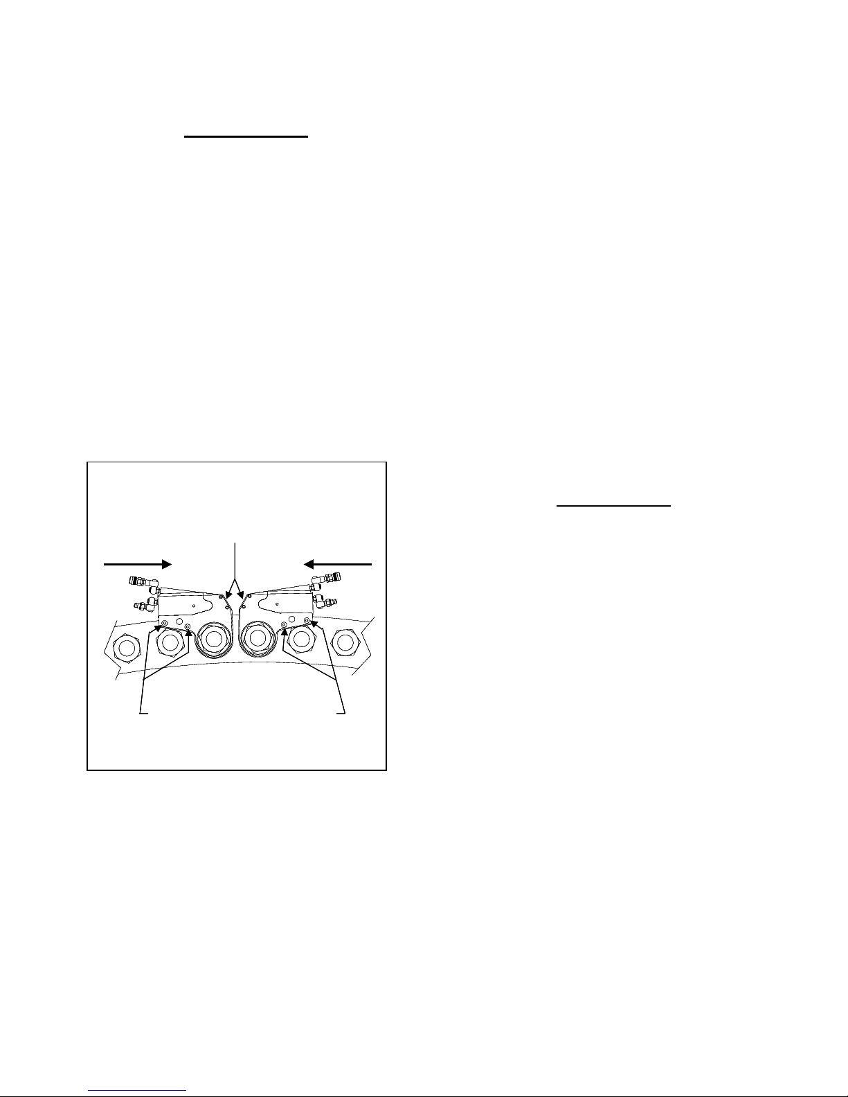
Wrench Positions
Dwg. 2
SHROUD
SHROUDSHROUDSHROUD
TIGHTEN LOOSEN
TIGHTENTIGHTEN LOOSENLOOSEN
REACT BETWEEN THESE POINTS
REACT BETWEEN THESE POINTS
OPERATING THE WRENCH
The position of the tool relative to the nut determines
whether the action will tighten or loosen the nut. (Refer
to Dwg. 2 for application examples). The power stroke
of the Piston Assembly will always turn the Ratchet Hex
toward the Shroud.1.Place the Ratchet Hex on the nut.
Make certain it is the correct size for the nut and that it
fully engages the nut.
2. Position the reaction surface against an adjacent nut,
flange or solid system component. Make certain that
there is clearance for the hoses, swivels, and inlets. DO
NOT allow the tool to react against the hoses, swivels,
or inlets.
3. After having turned the Pump on and presetting the
pressure for the correct torque, depress the remote
control button to advance the Piston Assembly. If the
notch in the piston rod did not engage the Retract Pin in
the Ratchet Link when the Link was joined to the
Housing, it will engage the Pin automatically during the
first advance stroke.
4. When the Link is connected to the Housing and the
wrench is started, the reaction surface of the wrench will
move against the contact point and the nut will begin to
turn.
5. When the nut is no longer turning and the Pump
Gauge reaches the preset pressure, release the remote
control button. The piston rod will retract when the
button is released and under normal conditions, an
audible “click” will be heard as the tool resets itself.
6. Continue to cycle the tool until it “stalls” and the
preset psi/torque has been attained.
7. Once the nut stops rotating, cycle the tool one last
time to achieve total torque.
LUBRICATION
Marine Moly Grease
Lubrication frequency is dependent on factors known
only to the user. The amount of contaminants in the
work area is one factor. Tools used in a clean room
environment will obviously require less service than a
tool used out-doors and dropped in loose dirt or sand.
Marine Moly Grease is formulated not to wash out of the
tool in areas where lubrication is critical. Whenever
lubrication is required, lubricate as follows:
1. Separate the Low Profile Cylinder from the Ratchet
Link if they are joined.
2. After wiping of the old grease, apply a daub of Marine
Moly Grease to the hooking notch in the Piston rod
and wipe a film of Marine Moly Grease onto the sides
and faces of the two Sliders.
3. Disassemble the Ratchet Link as instructed in the
Maintenance Section and wash the componen ts in a
suitable cleaning solution in a well-ventilated area.
4. Dry the components, then wipe a film of Marine Moly
Grease onto the wear surface of both Side Plate
Sleeves and the hubs of the Ratchet.
5. Spread a light film of Marine Moly Grease onto the
inner faces of both Side Plates covering the area where
the Drive and Segment Pawl travel. DO NOT pack the
teeth of the Segment Pawl or Ratchet with lube. It can
prevent the teeth from engaging properly.
6. Reassemble the Ratchet Link as instructed in the
Maintenance Section.

TX Series Torque Conversion Chart
5/20
Bar/N.M.
Hex
3/4" to 1-13/16" 1-7/8" to 2-3/8" All Hex SizesAll Hex Sizes2-5/8" to 3-15/16" 4" to 4-5/8" 2-7/16" to 4-5/8" 4-11/1 6" to 6-1 /2"
Sizes
19 to 46MM 47 to 60MM All Hex SizesAll Hex Sizes 65 to 100MM 105 to 115MM 80 to 115MM 115 to 155MM
Bar
68
82
95
109
122
136
150
163
177
190
204
218
231
245
258
272
286
299
313
326
340
354
367
381
394
408
422
435
449
462
476
490
503
517
530
544
558
571
585
598
612
626
639
653
666
680
1,045 1,159 2,142 4,853 8,452 9,015 17,895 20,063
1,093 1,212 2,250 5,063 8,879 9,466 18,790 21,066
1,145 1,270 2,359 5,275 9,299 9,916 19,685 22,069
1,197 1,328 2,460 5,485 9,720 10,368 20,579 23,072
1,250 1,385 2,569 5,696 10,147 10,818 21,474 24,075
1,307 1,450 2,677 5,908 10,567 11,333 22,367 25,079
1,353 1,507 2,786 6,152 10,987 11,786 23,266 26,082
1,406 1,566 2,894 6,396 11,414 12,240 24,165 27,085
1,457 1,624 2,996 6,640 11,834 12,692 25,064 28,088
1,510 1,682 3,104 6,884 12,261 13,147 25,962 29,091
1,567 1,742 3,213 7,128 12,682 13,692 26,861 30,094
1,613 1,799 3,321 7,334 13,102 14,148 27,719 31,097
1,666 1,857 3,430 7,540 13,522 14,604 28,577 32,101
1,718 1,914 3,531 7,747 13,949 15,061 29,435 33,104
1,769 1,972 3,640 7,953 14,369 15,518 30,460 34,107
1,829 2,033 3,748 8,161 14,796 15,888 31,153 35,110
1,873 2,089 3,857 8,386 15,217 16,342 32,044 36,113
1,926 2,146 3,965 8,611 15,637 16,796 32,934 37,116
1,979 2,204 4,067 8,837 16,064 17,250 33,825 38,119
2,029 2,262 4,175 9,062 16,484 17,630 34,716 39,123
2,090 2,325 4,284 9,289 16,911 18,314 35,605 40,126
2,134 2,379 4,392 9,520 17,331 18,772 36,495 41,129
2,187 2,437 4,501 9,754 17,752 19,231 37,386 42,132
2,238 2,494 4,602 9,985 18,172 19,687 38,277 43,135
2,291 2,553 4,711 10,219 18,599 20,146 39,167 44,138
2,352 2,615 4,819 10,452 19,019 20,361 40,058 45,141
2,394 2,669 4,928 10,701 19,446 20,814 40,947 46,145
2,447 2,726 5,029 10,951 19,866 21,267 41,837 47,148
2,498 2,784 5,138 11,200 20,287 21,718 42,726 48,151
2,551 2,843 5,246 11,449 20,714 22,171 43,615 49,154
2,614 2,908 5,355 11,699 21,141 22,503 44,504 50,157
TX-2 TX-4 TX-8 TX-16 TX-32
N.m. N.m. N.m. N.m. N.m. N.m. N.m. N.m.
260 285 535 1,125 2,115 2,250 4,324 5,016
312 342 644 1,357 2,535 2,700 5,260 6,019
365 399 752 1,590 2,955 3,150 6,195 7,022
416 455 854 1,822 3,382 3,600 7,130 8,025
469 512 962 2,055 3,802 4,051 8,066 9,028
522 569 1,071 2,288 4,229 4,501 8,996 10,031
572 626 1,179 2,528 4,650 4,951 9,871 11,035
625 683 1,288 2,768 5,070 5,401 10,747 12,038
678 740 1,389 3,008 5,490 5,851 11,623 13,041
728 797 1,498 3,248 5,917 6,301 12,499 14,044
784 868 1,606 3,489 6,337 6,751 13,374 15,047
832 923 1,715 3,762 6,764 4,826 14,250 16,050
885 981 1,823 4,034 7,185 7,651 15,126 17,053
937 1,038 1,925 4,307 7,605 8,101 16,002 18,057
990 1,097 2,033 4,579 8,032 8,551 16,877 19,060

6/20
Hex
Sizes
P.S.I.
1,000
1,200
1,400
1,600
1,800
2,000
2,200
2,400
2,600
2,800
3,000
3,200
3,400
3,600
3,800
4,000
4,200
4,400
4,600
4,800
5,000
5,200
5,400
5,600
5,800
6,000
6,200
6,400
6,600
6,800
7,000
7,200
7,400
7,600
7,800
8,000
8,200
8,400
8,600
8,800
9,000
9,200
9,400
9,600
9,800
10,000
TX Series Torque Conversion Chart
P.S.I./FT./lbs
TX-2 TX-4 TX-8 TX-16 TX-32
3/4" to 1-13/16" 1-7/8" to 2-3/8 " All He x SizesAll Hex Sizes2-5/8" to 3-15/16" 4" to 4-5/8" 2-7/16" to 4-5/8" 4-11/16" to 6-1/2"
19 to 46MM 47 to 60MM All Hex SizesAll Hex Sizes 65 to 100MM 105 to 115MM 80 to 115MM 115 to 155MM
ft./lbs. ft./lbs. ft./lbs. ft./lbs. ft./lbs. ft./lbs. ft./lbs. ft./lbs.
192 210 395 830 1,560 1,660 3,190 3,700
230 252 475 1,001 1,870 1,992 3,880 4,440
269 294 555 1,173 2,180 2,324 4,570 5,180
307 336 630 1,344 2,495 2,656 5,260 5,920
346 378 710 1,516 2,805 2,988 5,950 6,660
385 420 790 1,688 3,120 3,320 6,636 7,400
422 462 870 1,865 3,430 3,652 7,282 8,140
461 504 950 2,042 3,740 3,984 7,928 8,880
500 546 1,025 2,219 4,050 4,316 8,574 9,620
537 588 1,105 2,396 4,365 4,648 9,220 10,360
578 640 1,185 2,574 4,675 4,980 9,866 11,100
614 681 1,265 2,775 4,990 3,560 10,512 11,840
653 724 1,345 2,976 5,300 5,644 11,158 12,580
691 766 1,420 3,177 5,610 5,976 11,804 13,320
730 809 1,500 3,378 5,925 6,308 12,450 14,060
771 855 1,580 3,580 6,235 6,650 13,201 14,800
806 894 1,660 3,735 6,550 6,983 13,861 15,540
845 937 1,740 3,891 6,860 7,315 14,521 16,280
883 980 1,815 4,046 7,170 7,648 15,181 17,020
922 1,022 1,895 4,202 7,485 7,980 15,841 17,760
964 1,070 1,975 4,358 7,795 8,360 16,500 18,500
998 1,112 2,055 4,538 8,105 8,694 17,163 19,240
1,037 1,155 2,135 4,718 8,420 9,029 17,826 19,980
1,075 1,198 2,210 4,898 8,730 9,363 18,489 20,720
1,114 1,241 2,290 5,078 9,045 9,698 19,152 21,460
1,156 1,285 2,370 5,258 9,355 10,100 19,815 22,200
1,190 1,327 2,450 5,410 9,665 10,437 20,448 22,940
1,229 1,370 2,530 5,562 9,975 10,773 21,081 23,680
1,267 1,412 2,605 5,715 10,290 11,110 21,714 24,420
1,305 1,455 2,685 5,867 10,600 11,447 22,470 25,160
1,349 1,500 2,765 6,020 10,915 11,720 22,981 25,900
1,382 1,541 2,845 6,186 11,225 12,055 23,638 26,640
1,421 1,583 2,925 6,352 11,535 12,390 24,295 27,380
1,460 1,626 3,000 6,519 11,850 12,725 24,952 28,120
1,497 1,669 3,080 6,685 12,160 13,005 25,609 28,860
1,542 1,715 3,160 6,852 12,475 13,510 26,265 29,600
1,574 1,755 3,240 7,023 12,785 13,848 26,922 30,340
1,613 1,798 3,320 7,195 13,095 14,186 27,579 31,080
1,651 1,840 3,395 7,366 13,405 14,523 28,236 31,820
1,690 1,883 3,475 7,538 13,720 14,861 28,893 32,560
1,735 1,929 3,555 7,710 14,030 15,020 29,550 33,300
1,766 1,969 3,635 7,894 14,345 15,354 30,206 34,040
1,805 2,011 3,710 8,078 14,655 15,688 30,862 34,780
1,843 2,054 3,790 8,262 14,965 16,021 31,518 35,520
1,882 2,097 3,870 8,446 15,280 16,355 32,174 36,260
1,928 2,145 3,950 8,630 15,595 16,600 32,830 37,000
 Loading...