

TorcUP TU-2, TU-11, TU-3, TU-20, TU-7 Operation And Maintenance Manual
...
TU Series
OPERATION AND MAINTENANCE
MANUAL
TU Series Hydraulic Torque Wrenches
MODELS TU-2, TU-3, TU-7, TU-11, TU-20, TU-27 & TU-60
1025 Conroy Place, Easton, PA. 18040 * U.S.A.
Phone: +1 610-250-5800 * Fax: +1 610-250-2700
Toll Free: 1-888-TORCUP-1
Email: sales@torcup.com * Website: www.torcup.com

Operational and Maintenance Manual for TorcUP
1/21
TU-2, TU-3, TU-11, TU-20 ,TU-27 AND TU-60
Square Drive Hydraulic Torcque Wrenches
Version 1: 2015 February
Series TU-2, TU-3, TU-7, TU-11, TU-20, TU-27 and TU-60 Square Drive Hydraulic Torque Wrenches
are designed for installing and removing threaded fasteners requiring precise high torque during bolt
makeup and maximum torque during bolt breakout.
TorcUP Inc. is not responsible for customer modication of tools for applications on which TorcUP Inc.
was not consulted.
IMPORTANT SAFETY INFORMATION ENCLOSED.
READ THIS MANUAL BEFORE OPERATING TOOL.
IT IS THE RESPONSIBILITY OF THE EMPLOYER TO PLACE THE INFORMATION IN THIS
MANUAL INTO THE HANDS OF THE OPERATOR.
FAILURE TO OBSERVE THE FOLLOWING WARNINGS COULD RESULT IN INJURY.
USING THE TOOL
• Always operate, inspect and maintain this tool in accordance with American National Standards Safety
Code for Hydraulic Rams and Jacks (ANSI B30.1)
• This tool will function using an air or electric powered hydraulic pump. Adhere to the pump safety require
ments and follow instructions when connecting the pump to the tool.
• Use only equipment rated for the same pressure and torque.
• Use only a hydraulic pump capable of generating 10,000 psig (681 bar) maximum pressure with this tool.
• Use only twin line hydraulic hose rated for 10,000 psig (681 bar) pressure with this tool.
• Do not interchange the male and female swivel inlets on the tool or the connections on one end of the
hose. Reversing the inlets will reverse the power stroke cycle and may damage the tool.
• Do not use damaged, frayed or deteriorated hoses and ttings. Make certain there are no cracks, splits
or leaks in the hoses.
• Use the quick connect system to attach the hoses to the tool and pump. Make certain the spring-loaded
retaining rings are fully engaged and the safety rings are tightly threaded against the spring-loaded retain
ing rings to prevent the connectors from disengaging under pressure.
• When connecting hoses that have not been preloaded with hydraulic oil, make certain the pump reservoir
is not drained of oil during start-up.
• Do not remove any labels. Replace any damaged label.
• Do not handle pressurized hoses. Escaping oil under pressure can penetrate the skin, causing serious
injury. If oil is injected under the skin, see a doctor immediately.
• Never pressurize uncoupled couplers. Only use hydraulic equipment in a coupled system.
• Always wear eye protection when operating or performing maintenance on this tool.
• Always wear head and hand protection and protective clothing when operating this tool.
The use of other than genuine TorcUP replacement parts may result in safety
hazards, decreased tool performance, and increased maintenance, and may
invalidate all warranties. Repairs should be made only by authorized
personnel. Consult your nearest TorcUP Authorized Service Center.
Refer All Communications to the Nearest TorcUP Ofce or Distributor.
For Technical Support & Information Contact:
TorcUP Inc.
1025 Conroy Place, Easton, PA 18040 USA
Phone: +1 610-250-5800 Fax:+1 610-250-2700
email: sales@torcup.com
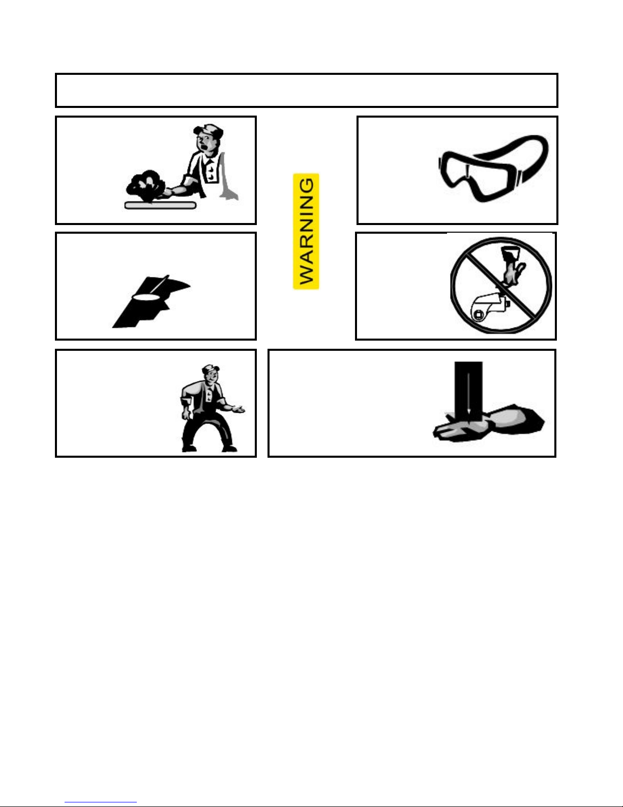
FAILURE TO OBSERVE THE FOLLOWING WARNINGS COULD RESULT IN INJURY
2/21
Do NOT exceed Maximum Pressure. See Torque Chart with Tool. Damage May Occur.
Do not use damaged,
frayed or deteriorated
hydraulic hoses
and ttings.
Always wear ear protection
when operating this tool.
Keep body stance
balanced and rm.
Do not overreach
when operating this
tool.
Always wear eye
protection
when
operating or
performing
maintenance
on this tool.
Do not carry
the tool
by the hose.
The Torque Reaction Arm must be
positioned against a positive stop.
Do not use the arm as a dead
handle. Take all precautions to
make certain the operator’s hand
cannot be pinched between the
arm and a solid object.
USING THE TOOL
• Keep hands, loose clothing & long hair away from the reaction arm and working area during operation.
• This tool will exert a strong reaction force. Use proper mechanical support and correct reaction arm
positioning to control these forces. Do not position the reaction arm so that it tilts the tool off the axis of
the bolt and never use the swivel inlets as a reaction stop.
• Avoid sharp bends and kinks that will cause severe back-up pressure in hoses an lead to premature
hose failure.
• Use accessories recommended by TorcUP.
• Use only impact sockets and accessories. Do not use hand (chrome) sockets or accessories.
• Use only sockets and accessories that correctly t the bolt or nut and function without tilting the tool off
the axis of the bolt.
• This tool is not insulated against electric shock.
• This equipment must not be operated or serviced unless the operator read the operating instructions
and fully understands the purpose, consequences and procedure of each step.
• When operating a larger tool (TU-20, TU-27 or TU-60) above waist height, employ a secondary means
of support for safety purposes. A tool sling or chains may be used. Consult your safety department for
further suggestions.
Depending on the working environment your local health and safety regulations may require
you protective gear (i.e. Ear Protection, Safety Shoes, Hard Hat, Gloves, Coveralls, etc.) In
case external forces are exerted on the equipment, non-compliance with these regulations may
result in injury. EAR PROTECTION MUST BE WORN WHEN OPERATING THIS TOOL.

PLACING THE TOOL IN SERVICE
3/21
CONNECTING THE TOOL
1. Attach the twin line hose to the swivel inlets of the square drive torque wrench using the
spring–loaded quick connect ends. After making certain that they are fully engaged,
thread the safety rings tightly against the spring–loaded retainer rings.
2. Connect the opposite ends of the hose to the pump in the same manner.
ADJUSTMENTS
SETTING THE SQUARE DRIVE FOR ROTATION
The position of the square drive when looking toward the shroud will determine if the tool is
set to tighten or loosen the nut. When the square drive extends to the left when looking at
the shroud with the inlets away from you, the tool is set to loosen the nut. When the square
drive extends to the right, the tool is set to tighten the nut. To change the direction of rotation
for model TU-2 TU-3, TU-7 and TU-11 simply push the square drive into the housing until the
drive projects out the opposite side of the tool. For model TU-20, TU-27 & TU-60, loosen and
remove the square drive retaining screw and pull the square drive out of the housing. Insert
the square drive into the opposite side of the housing and secure it by installing the screw in
the splined end of the drive.
SETTING THE TORQUE
After determining the desired torque, use the calibration certicate provided with the tool to
determine the pressure necessary to achieve that torque. You may also refer to the chart
engraved on the shroud of the tool or the chart provided on page 7 of this manual.
1. Connect the tool to the power supply and turn the pump on.
2. Depress the remote control button causing the pressure to be shown on the gauge.
3. Adjust the pressure by loosening the wing nut that locks the pressure adjustment thumb
screw. Rotate the thumbscrew clockwise to increase the pressure and counterclockwise
to decrease the pressure. When decreasing pressure, always lower the pressure below
the desired point and then bring the gauge back up to the desired pressure.
4.When the desired pressure is reached, retighten the wing nut and cycle the tool again to
conrm that the desired pressure setting has been obtained.
SETTING THE REACTION ARM
REACTION
CONTACT
POINTS
REACTION
CONTACT
POINTS
REACTION
CONTACT
POINTS
REACTION
CONTACT
POINTS
4/21
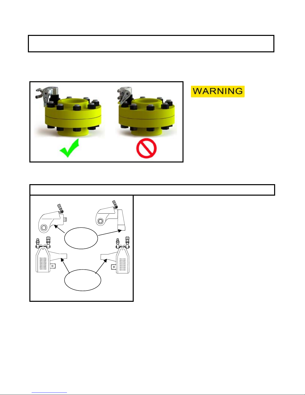
The function of a reaction device is to hold the tool in position against the forces generated to
tighten or loosen bolts or nuts. Hydraulic wrenches generate tremendous force.
An improperly
positioned reaction
arm may result in
operator injury
or damage tooling.
Square Drive Hydraulic Wrench Reaction Points (Dwg.01)
Make sure the reaction arm is positioned correctly.
(Refer to Dwg. 01).
The reaction arm can be positioned numerous
O
places within a 360
circle. However, for the arm to
be correctly positioned, it must be set within a 90O
quadrant of that circle. That quadrant is the area
located between the protruding square drive and
the bottom of the housing away from the swivel
inlets. It will always be toward the lower half of the
housing and on one side of the housing when
tightening and the other side when loosening.
OPERATING THE WRENCH
5/21
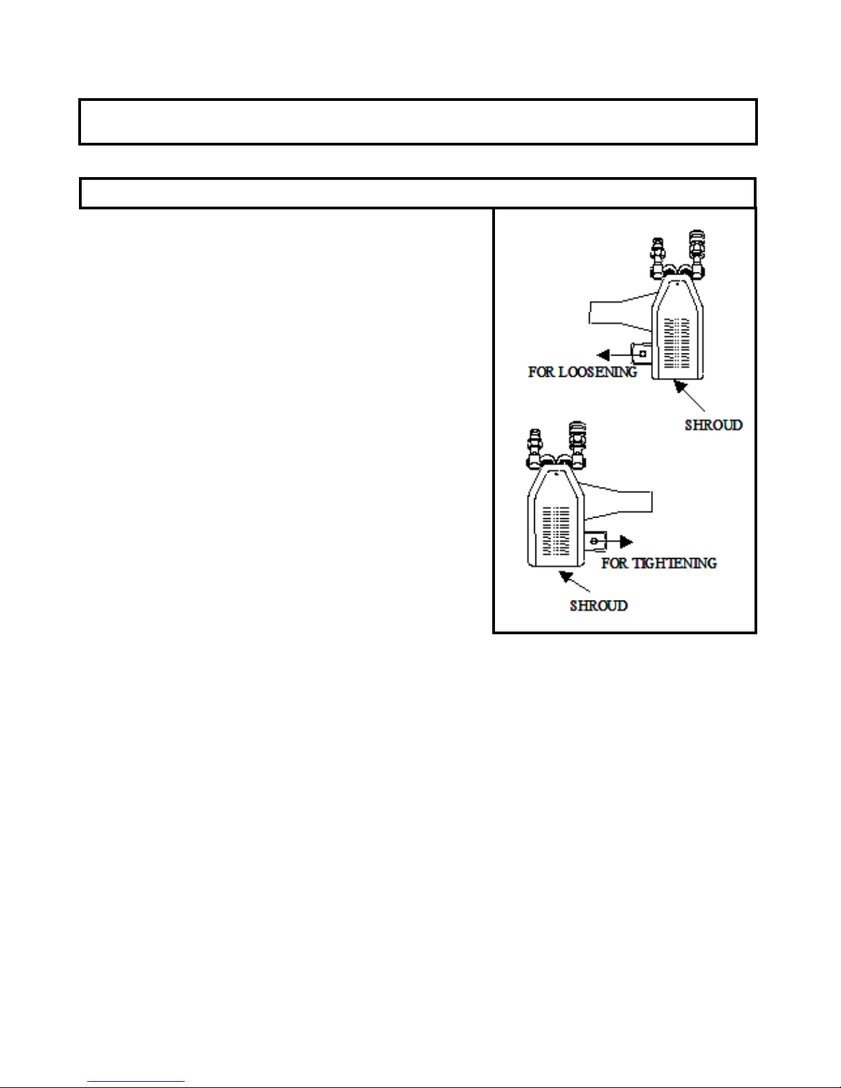
Square Drive Position for Loosening and Tightening(Dwg.02)
The position of the square drive relative to the shroud
determines whether the action will tighten or loosen the
nut. (Refer to Dwg. 02 for application examples).
The power stroke of the piston assembly will always
turn the square drive toward the shroud.
1. Place the square driver in the socket and the socket
on the nut. Make certain the square driver and socket
are the correct size for the nut and that the driver fully
engages the socket and the socket fully engages the
nut.
2. Position the reaction arm or surface against an
adjacent nut, ange or solid system component.
Make certain that there is clearance for the hoses,
swivels, inlets and end plug. DO NOT allow the tool
to react against the hoses, swivels, inlets or end plug.
3. After having turned the pump on and presetting the
pressure for the correct torque, depress the remote control button to advance the
piston assembly.
4. When the wrench is started, the reaction surface of the wrench or reaction arm will move
against the contact point and the nut will begin to turn.
5. When the nut is no longer turning and the pump gauge reaches the preset pressure,
release the remote control button. The piston rod will retract when the button is released
and under normal conditions, an audible “click” will be heard as the tool resets itself.
6. Continue to cycle the tool until it “stalls” and the preset psi/torque has been attained.
7. Once the nut stops rotating, cycle the tool one last time to achieve total torque.

LUBRICATION
6/21
Marine Moly Grease
Lubrication frequency is dependent on factors known only to the user. The amount of
contaminants in the work area is one factor. Tools used in a clean room environment will
obviously require less service than a tool used out-doors and dropped in loose dirt or sand.
Marine Moly Grease is formulated not to wash out of the tool in areas where
lubrication is critical.
Whenever lubrication is required, lubricate as follows:
1. Remove the drive plate, ratchet, drive segment and sleeves as instructed in the
maintenance section and wash the components in a suitable cleaning solution in a well
ventilated area.
2. After drying the components, wipe a lm of Marine Moly Grease onto the wear
surface of both sleeves and the ends of the ratchet.
3. Spread a light lm of Marine Moly Grease onto the inner face and both sides of the Drive
Plate. Do not pack the teeth of the drive segment or ratchet with lube. It can prevent the
teeth from engaging properly.
4. Place a daub of Marine Moly Grease in the piston rod recess of the drive plate before
linking the piston rod to the drive plate at assembly.
CRITICAL LUBRICATION
It is imperative to lubricate the piston rod recess of the drive plate to piston rod contact area
every 80 hours of continuous duty cycling.
Lubricate as follows:
1. Remove shroud screws, shroud, and roll pin.
2. Pry the drive plate assembly forward from the piston rod to expose the recessed
contact area in the drive plate.
3. With a rag, wipe clean the area and apply a sizeable amount of Marine Moly Grease.
4. Reassemble as instructed in the maintenance section.
 Loading...