

Page 1
Page 2
WARNING
IMPORTANT SAFETY INFORMATION ENCLOSED.
READ THIS MANUAL BEFORE OPERATION.
IT IS THE RESPONSIBLITIY OF THE EMPLOYER TO PLACE THE INFORMATION IN THIS MANUAL INTO
THE HANDS OF THE OPERATOR.
FAILURE TO OBSERVE THE FOLLOWING WARNINGS COULD RESULT IN INJURY.
The use of other than genuine TorcUP replacement parts may result in safety hazards, decreased tool
performance, and increased maintenance, and may invalidate all warranties.
Repairs should be made only by authorized personnel. Consult your nearest TorcUP Authorized
Service Center. Refer all communications to the nearest TorcUP Office or Distributor.
WARNING
For Technical Support and Information Contact:
TorcUP, Inc.
1025 Conroy Place, Easton, PA 18040
Toll Free: (888) TORCUP-1 Fax: (610) 250-2700
E-mail: [email protected]
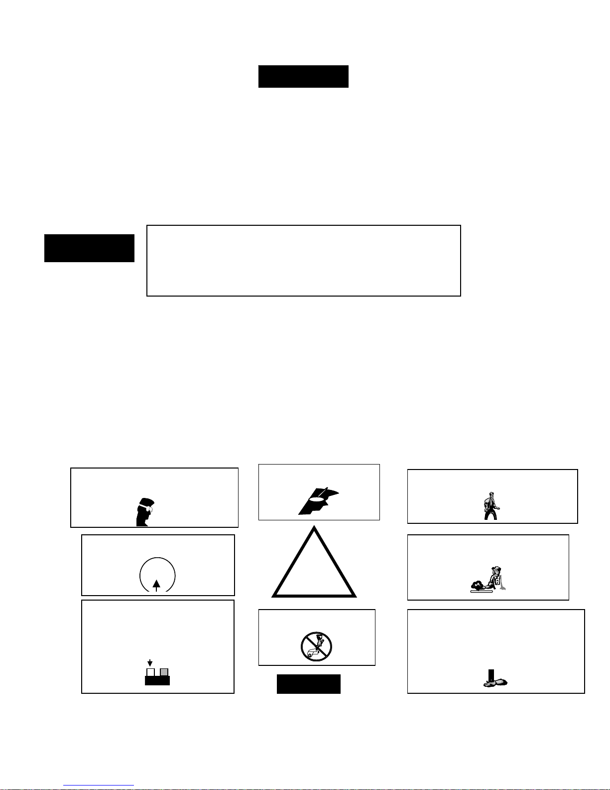
FAILURE TO OBSERVE THE FOLLOWING WARNINGS COULD RESULT IN INJURY
• Keep hands, loose clothing and long hair
away from the reaction arm and working area
during operation. Do not attempt to support the
tool with your hands during operation.
• This tool will exert a strong reaction force.
Use proper mechanical support and correct
reaction arm positioning to control these
forces. Do not position the reaction arm so that
it tilts the tool off the axis of the bolt and never
use the swivel inlets as a reaction stop.
Avoid sharp bends and kinks that will cause
severe back-up pressure in hoses and lead to
premature hose failure.
• Use accessories recommended by TorcUP.
• Use only impact sockets and accessories. Do
not use hand (chrome) sockets or accessories.
• Use only sockets and accesssories that
correctly fit the bolt or nut and function without
tilting the tool off the axis of the bolt.
• This tool is not designed for working in
explosive atmospheres
Always wear eye protection when operating
Always wear eye protection when operating
or performing maintenance on this tool.
or performing maintenance on this tool.
Always wear ear protection
when operating this tool.
Keep body stance balanced and firm. Do
not overreach when operating this tool.
!
the hose.
Do not use damaged, frayed or
deteriorated hydraulic hoses and
fittings.
The Torque Reaction Arm must be
positioned against a positive stop. Do not
precautions to make certain the operator’s
hand cannot be pinched between the Arm
use the Arm as a dead handle. Take all
and a solid object.
Operate at 10,000 psig (681bar)
maximum pressure.
10,000 psig
10,000 psig
(681 bar)
Always turn off the pump and
disconnect the power before
installing, removing, or adjusting
any accessory on this tool, or
before performing any maintenance
(681 bar)
on this tool.
ON
ON
OFF
OFF
POWER
POWER
Do not carry the tool by
NOTICE
SAVE THESE INSTRUCTIONS. DO NOT DESTROY.
-
Page 3
••• 1 •••
EP500 & EP1000
TORQUE PUMPS
Rev. - A
Date - 0709
CO NTENTS
Receiving Instructions and Warranty Statement .........................................................................................................1
Safe and Correct Use ............................................................................................................................................... 2-3
Technical Specifications ...............................................................................................................................................4
Working Pressure .........................................................................................................................................................4
Install Vent Plug ............................................................................................................................................................4
Adding Oil .....................................................................................................................................................................4
Install Hydraulic Connections .......................................................................................................................................5
Electrical .......................................................................................................................................................................5
Connecting Hydraulic Tools...................................... ....................................................................................................5
Starting the Pump for the First Time ............................................................................................................................5
Pump Mounting ............................................................................................................................................................6
Control Valves ...............................................................................................................................................................6
Power Control Switches ...............................................................................................................................................6
Pressure Torque Setting ...............................................................................................................................................7
After Completing the Job .............................................................................................................................................7
Periodic Maintenance ...................................................................................................................................................7
Maintain Oil Level .........................................................................................................................................................8
Clean Oil Intake Screen ................................................................................................................................................8
Flushing the Pump .......................................................................................................................................................8
Problem / Cause - Solutions ........................................................................................................................................9
- Note -
TorcUP has taken every care in preparing this Operational Manual that is intended as a technical guideline only.
TorcUP accepts no liability in relation to any use or reliance made of any information in this Operational Manual.
All information, illustrations and specications in this Operational Manual are based on the latest information
available at the time of publication. The right is reserved to make changes at any time without notice.
Equipment operators and installers shall be responsible for ensuring that a safe working environment and safe
systems of work are in place before operating the equipment.
www.torcup.com
Page 4
EP Torque Pumps
••• 2 •••
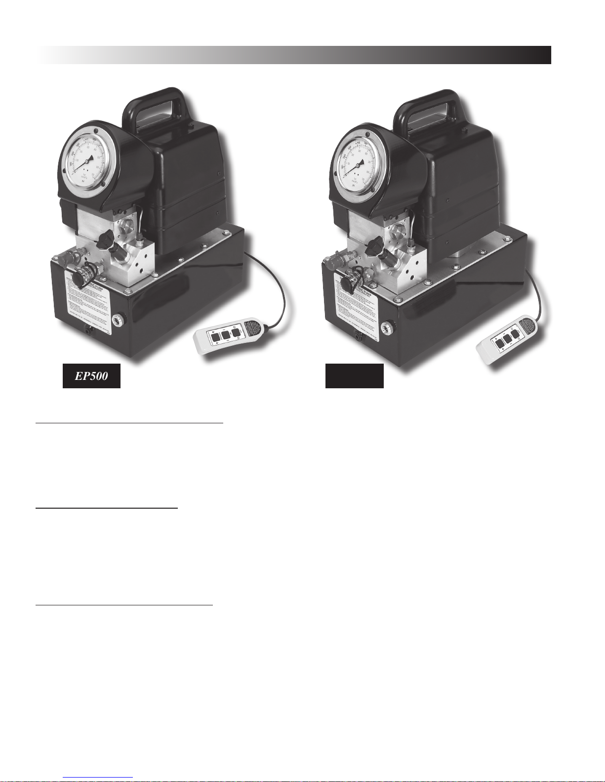
EP500
EP1000
IMPORTANT - READ CAREFULLY
This manual contains important information for the correct installation, operation and maintenance of this
equipment. All persons involved in the installation, operation and maintenance of this equipment must be
thoroughly familiar with the contents of this manual. To safeguard against the possibility of personal injury or
property damage, follow the recommendations and instructions of this manual. Keep this manual for reference.
WARRANTY STATEMENT
TorcUP products are warranted to be free of defects in materials and workmanship under normal use for
as long as the original purchaser owns them, subject to the guidelines and limitations listed. This warranty does
not cover: normal wear & tear, cosmetic items, abuse, overloading, alterations, improper fluid, or use in a
manner for which they are not intended. If the customer believes a product is defective, the product must be
delivered, or shipped freight prepaid, to the nearest TorcUP Authorized Service Center for evaluation and
repair.
1.0 RECEIVING INSTRUCTIONS
Important! Make sure to inspect all of the components for shipping damage. If damage is found, notify carrier at
once. Shipping damage will not be covered by warranty. The carrier is responsible for all loss associated with
shipping damage.
www.torcup.com
Page 5
••• 3 •••
2.0 SAFETY
Make sure to read the instructions, warnings and precautions carefully. Follow any recommended safety precautions
to avoid personal injury or damage to the unit. TorcUP cannot be responsible for any damage or injury from unsafe
use, lack of maintenance or incorrect operation. In the event any questions or concerns arise, contact TorcUP or a
local Distributor for clarication.
The pump’s maximum working pressure is 10,000 PSI (700kg/cm2). Make
sure that all hydraulic equipment such as rams, hoses, etc. used with this
pump are rated at 10,000 PSI (700kg/cm2) operating pressure.
If you have never been trained on high-pressure hydraulic safety, consult
your distributor or service center for a free TorcUP Hydraulic Safety Course.
Failure to comply with the following cautions and warnings could cause equipment damage, property damage or
personal injury.
DANGER is only used when your action or lack of action may cause serious injury or even death.
WARNING indicates a potential danger that requires correct procedures or practices to avoid personal injury.
CAUTION is used to indicate correct operating or maintenance procedures and practices to prevent damage
to, or destruction of equipment, or other property.
WARNING: Wear proper personal protective gear when operating hydraulic equipment.
DANGER: To avoid personal injury, keep hands and feet away from cylinder and work-piece during operation.
WARNING: Do not exceed equipment ratings. Overloading causes equipment failure and possible personal injury.
The wrenches are designed for a maximum pressure of 10,000 PSI (700kg/cm2). Never set the relief valve to a higher
pressure than the maximum rated pressure of the pump. Higher settings may result in equipment damage and/or
personal injury.
WARNING: The system operating pressure must not exceed the pressure rating of the lowest rated component in
the system. Install pressure gauges in the system to monitor operating pressure. It is your window to what is
happening in the system.
CAUTION: Avoid damaging hydraulic hose. Avoid sharp bends and kinks when routing hydraulic hoses. Using a
bent or kinked hose will cause severe back-pressure. Sharp bends and kinks will internally damage the hose, leading
to premature hose failure.
Do not drop heavy objects on hose. A sharp impact may cause internal damage to hose wire strands. Applying
pressure to a damaged hose may cause it to rupture.
IMPORTANT: Do not lift hydraulic equipment by the hose or swivel couplers. Use the carrying handle or other means
of safe transport.
CAUTION: Keep hydraulic equipment away from ames and heat. Excessive heat will soften seals, resulting in uid
leaks. Heat also weakens hose materials. For optimum performance do not expose equipment to temperatures of
65° C (170° F) or higher. Protect hoses and cylinders from weld spatter.
DANGER: Do not handle pressurized hoses. Escaping oil under pressure can penetrate the skin, causing serious
injury. If oil is injected under the skin, see a doctor immediately.
DANGER: Only use hydraulic cylinders in a coupled system. Never use a cylinder with unconnected couplers. If the
cylinder becomes severely overloaded, components can fail catastrophically causing severe personal injury or death.
www.torcup.com
Page 6
••• 4 •••
3.0 TECHNICAL SPECIFICATIONS
EP500 Electric Torque Wrench
Voltage 115V 230V
Operating Pressure 10,000 PSI (700kg/cm2)
Electrical Power Source 20 Amps 115V Grounded 50/60 Hz 10 Amps 220V Grounded 50/60 Hz
Motor Rating 1.125 Hp Single Phase
Flow Rate 554 cu. in./ min. @ 1,100 psi, 46 cu. in / min. @ 10,000 psi
Maximum Operating
Temperature
18 Amps @ 10,000 psi (700kg/cm2)
170F - (65C)
1.125 Hp Single Phase
10 Amps @ 10,000 psi (700kg/cm2)
EP1000 Electric Torque Wrench
Voltage 115V 230V
Operating Pressure 10,000 PSI (700kg/cm2)
Electrical Power Source 20 Amps 115V Grounded 50/60 Hz 10 Amps 220V Grounded 50/60 Hz
Motor Rating 1.5 Hp Single Phase
Flow Rate 575 cu. in./ min. @ 1,100 psi, 55 cu. in / min. @ 10,000 psi
Maximum Operating
Temperature
18 Amps @ 10,000 psi (700kg/cm2)
170F - (65C)
1.5 Hp Single Phase
10 Amps @ 10,000 psi (700kg/cm2)
4.0 WORKING PRESSURE
The pump’s maximum working pressure is 10,000 PSI (700kg/cm2). Make sure that all hydraulic equipment such as
rams, hoses, etc. used with this pump are rated at 10,000 PSI (700kg/cm2) operating pressure.
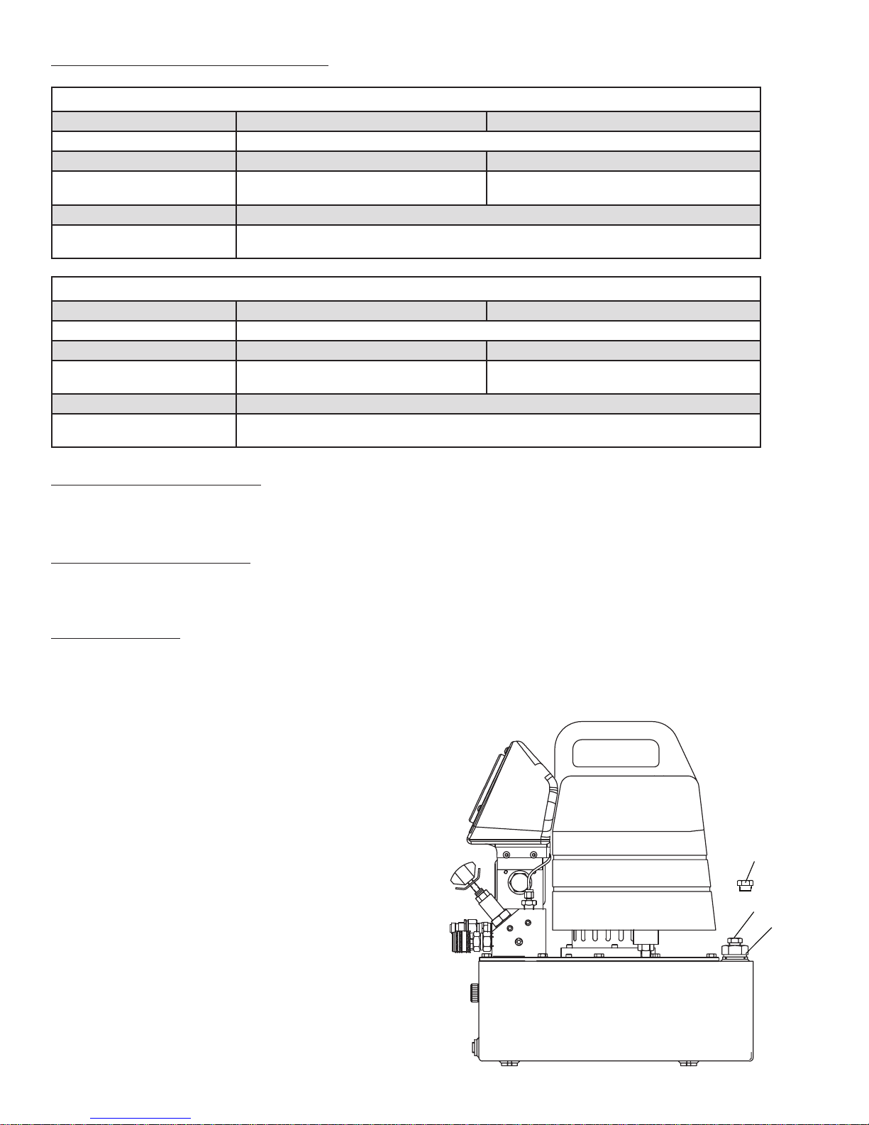
4.1 INSTALL VENT PLUG
Remove SHIPPING PLUG (A) and install VENT PLUG (B) into cover plate.
4.2 ADDING OIL
Remove OIL FILLER CAP (C) and add TorcUP Hydraulic Oil into reservoir. Oil level should not exceed 1” from the
reservoir cover.
*As a “rule of thumb” oil should be visual in site window when
the unit is powered down and all connected tools or cylinders
are retracted.
B
www.torcup.com
A
C
N O T E :
V e n t P l u g / O i l F i l l L o c a t i o n i s a p p l i c a b l e t o t h e
1 . 5 , 2 . 5 , 5 & 1 0 g a l l o n r e s e r v o i r s .
O n e g a l l o n m o d e l s u t i l i z e t h e d r a i n p l u g f o r
r e m o v i n g a n d a d d i n g o i l . V e n t p l u g a r e p r e - i n s t a l l e d
u n d e r t h e s h r o u d .
Page 7
••• 5 •••
“
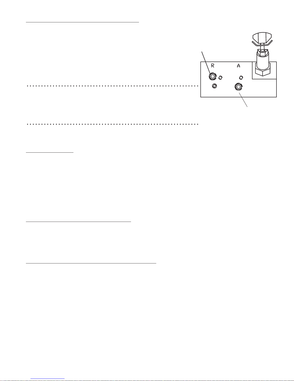
4.3 INSTALL HYDRAULIC CONNECTIONS
Use only cylinders, tools, hoses and accessories rated at 10,000 PSI
(700kg/cm2). Remove the shipping plugs from the ports to connect your
coupling(s) or hose(s) to manifold. Use 1.5 wraps of Teon tape (or suitable
thread sealant) on all threads, leaving the rst complete thread free of tape to
ensure no foreign matter enters the hydraulic circuit.
When making connections with quick disconnect couplings, make sure the
couplings are fully engaged. Threaded connections such as ttings, gauges,
etc. must be securely tightened and leak free.
WARNING: Loose or improperly threaded ttings can be potentially
dangerous if pressurized; however, severe over tightening can cause premature
thread failure. Fittings need to be tightened secure & leak free. Never hold or
stand directly in line with any hydraulic connections while pressurizing. Never
grab, touch or in any way come in contact with a hydraulic pressure leak.
Escaping oil can penetrate the skin and a serious injury can result.
CAUTION: Do not subject the hose to potential hazards such as sharp surfaces, extreme heat or heavy impact. Do
not allow the hose to kink or twist. Inspect each hose for wear before it is used.
B”
“A”
4.4 ELECTRICAL
Check for proper electrical supply before connecting. Be sure the electrical connection is grounded. Check that your
power supply agrees with the motor nameplate and/or TorcUP model decal.
NOTE: MOTOR MAY SPARK. DO NOT OPERATE IN AN EXPLOSIVE ATMOSPHERE OR IN THE PRESENCE OF
CONDUCTIVE LIQUIDS.
1. Do not use a power or extension cord that is damaged or has exposed wires.
2. All single phase motors come equipped with a three prong grounding type plug to t the
proper grounded type electrical outlet. Do not use a two prong ungrounded extension cord
as the pump’s motor must be grounded.
4.5 CONNECTING HYDRAULIC TOOLS
Use only tools, hoses and accessories rated at 10,000 PSI (700kg/cm2). When making connections with quick
disconnect couplings, make sure the couplings are fully engaged. Threaded connections such as ttings, gauges,
etc. must be securely tightened and leak free. Use 1.5 wraps of Teon tape (or suitable thread sealant) on all threads,
leaving the rst complete thread free of tape to ensure no foreign matter enters the hydraulic circuit.
4.6 STARTING THE PUMP FOR THE FIRST TIME
1. Locate the power switch on shroud and select to the “ON” position. Check for any leaks, repair as needed.
2. Shift pendant to the advance position to advance tool and release to retract tool. Look for movement in tool,
check for any leaks, repair as needed.
CAUTION: Never operate the pump without tool movement for more than 1 minute. Leaving the valve in the advance
or retract position without the tool’s piston rod moving will overheat the oil.
CAUTION: Never disconnect or connect any hydraulic hoses or ttings without rst unloading the tool, then unplug
the electrical cord of the pump. Open manual relief valve to assure that the system has been depressurized. View
the gauge reading and double check the gauge to assure pressure has been released.
www.torcup.com
Page 8
••• 6 •••
4.7 PUMP MOUNTING
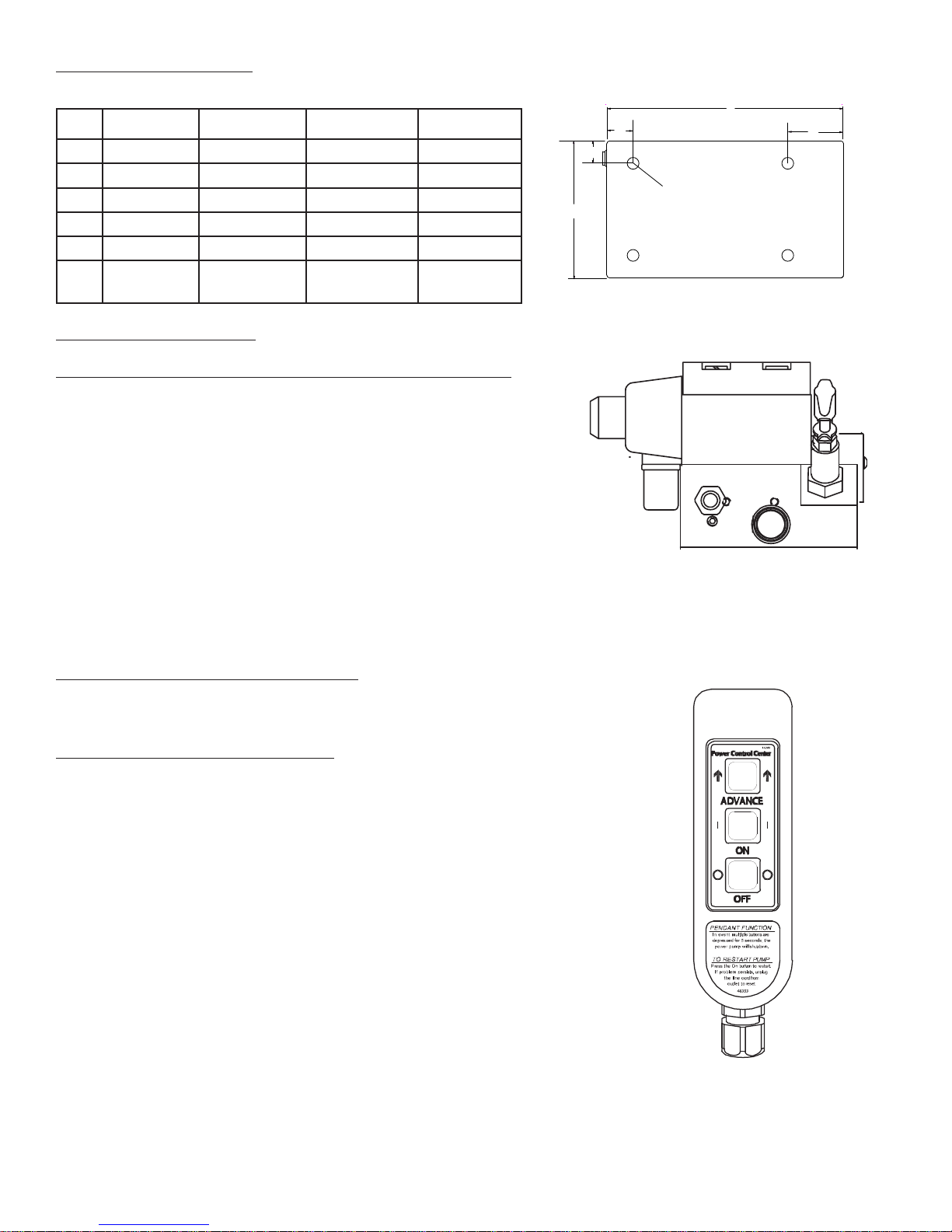
Refer to the chart for mounting dimensions to secure the pump to a xed surface.
1 gal. (4L) 1.5 gal.(6L) 2.5 gal.(10L) 5 gal. (20L)
A
B
C
D
E
F
11 15.13 17 19.6
0.56 1.68 2.75 4.69
0.56 3.57 4.37 5.03
1.16 1.43 1.93 2.93
8.19 8.75 9.75 11.75
1/4-20unc
(4 places)
1/4-20unc
(4 places)
1/4-20unc
(4 places)
1/4-20unc
(4 places)
A
B
D
F
E
C
5.0 CONTROL VALVES
2-Postion – 4 Way Solenoid Valve for Hydraulic Torque Wrenches.
• To Advance......depress the Advance Switch
• To Retract.........release advance switch to Retract Tool.
5.1 POWER CONTROL SWITCHES
Remote pendant.
Congured with motor control pendant:
ADVANCE = Press and hold switch to turn motor on.
Energizes ADV. Coil.
ON = Press switch to turn motor on.
OFF = Press switch to turn motor off.
2 Position - 4 Way Solenoid
Motor/Valve Control Pendant
NOTE: In the event multiple buttons are depressed for longer than 5 seconds, the unit is programmed to shut
down. To restart, you will need to depress the motor “ON” to continue, or unplug / re-plug the unit into power
supply, then depress the motor “ON” to continue.
www.torcup.com
Page 9
••• 7 •••
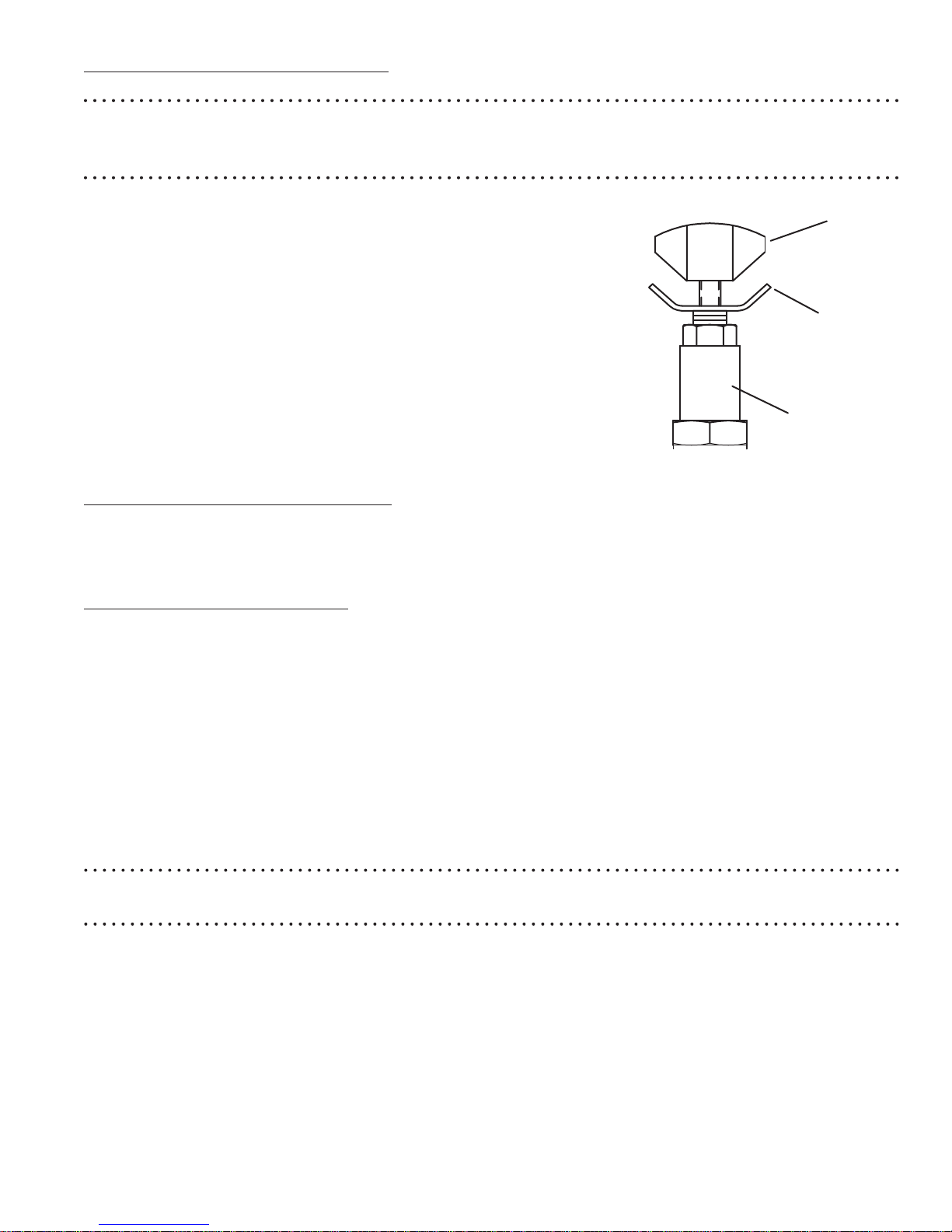
5.2 PRESSURE TORQUE SETTING
WARNING: Make these adjustments BEFORE putting torque wrench on nut or bolt head. The pump pressure
setting may be above the pressure needed to provide the required torque for your application.
Exceeding required torque will cause equipment damage and may lead to serious personal injury.
1. See torque wrench instructions for amount of pressure required
to produce desired torque.
2. Loosen lock nut and back out relief valve to prevent unintended
pressure build up.
3. Turn pump on. Press and the “ADVANCE” switch, and read
pressure gauge.
4. While holding the switch, turn relief valve in (clockwise)
to increase pressure or out (counter-clockwise)
to decrease maximum pressure. Repeat until
correct pressure is obtained.
5. Tighten lock nut on the relief valve to maintain setting.
6. Run pump several times to test this setting before
setting tool on the nut.
Adjusting Knob
Lock Nut
Valve Assembly
5.3 AFTER COMPLETING THE JOB
Before disconnecting hoses, ttings, etc., rst be sure the tool is unloaded and retracted, then unplug the power
cord. The pump is designed to cycle valve upon power down “off.”
6.0 PERIODIC MAINTENANCE
Completely change the hydraulic oil and clean the intake screen and magnet (located in the reservoir) twice a year.
If equipped, change the external oil lter twice a year (Use TorcUP oil only, Model # AO1, 1 gallon). Change the
oil more frequently when used in extremely dusty areas or when the oil has been overheated. Using oil other than
TorcUP Brand may void the pump’s warranty.
The following conditions require more frequent oil changes.
• Rigorous duty, where oil temperature may reach 150˚ F.
• High humidity environment and extreme changes in temperature that can result in condensation inside the
reservoir.
• Dirty or dusty environments that may contaminate the oil.
• Frequent connection and disconnection of hydraulic hoses and components.
WARNING: The electrical power cord must be disconnected from electrical outlets before performing maintenance
or repair procedures.
www.torcup.com
Page 10
••• 8 •••
6.1 MAINTAIN OIL LEVEL
Check hydraulic oil level every 30 hours of operation (sight gauge should be completely covered in oil when all tools
are retracted. Add TorcUP oil (Model # AO1 – 1 gallon) when necessary. Oil level should be no more than 1” from top
of reservoir plate – with cylinders retracted and motor off.
6.2 CLEAN OIL INTAKE SCREEN ONCE A YEAR
Loosen and remove reservoir plate bolts. Lift pump unit off the reservoir, being careful not to damage the gasket.
Applies to 1, 1.5, 2, 2.5 gallon reservoirs:
Remove the 5 Allen socket head cap screws securing the screen to the 1st stage gear pump. Care should be taken
not to remove the center plate and gears. Remove and clean with nonammable solvent, blow dry clean. Reinstall in
reverse order and torque bolts to 75 inch pounds. Keep the motor
and pump as clean as possible.
Applies to the 5 and 10 gallon reservoirs:
Unscrew screen from bottom of pump unit and clean with
nonammable solvent. Blow dry and reassemble. Keep areas
around pump unobstructed to provide good air ow around the
motor and pump. Keep the motor and pump as clean as possible.
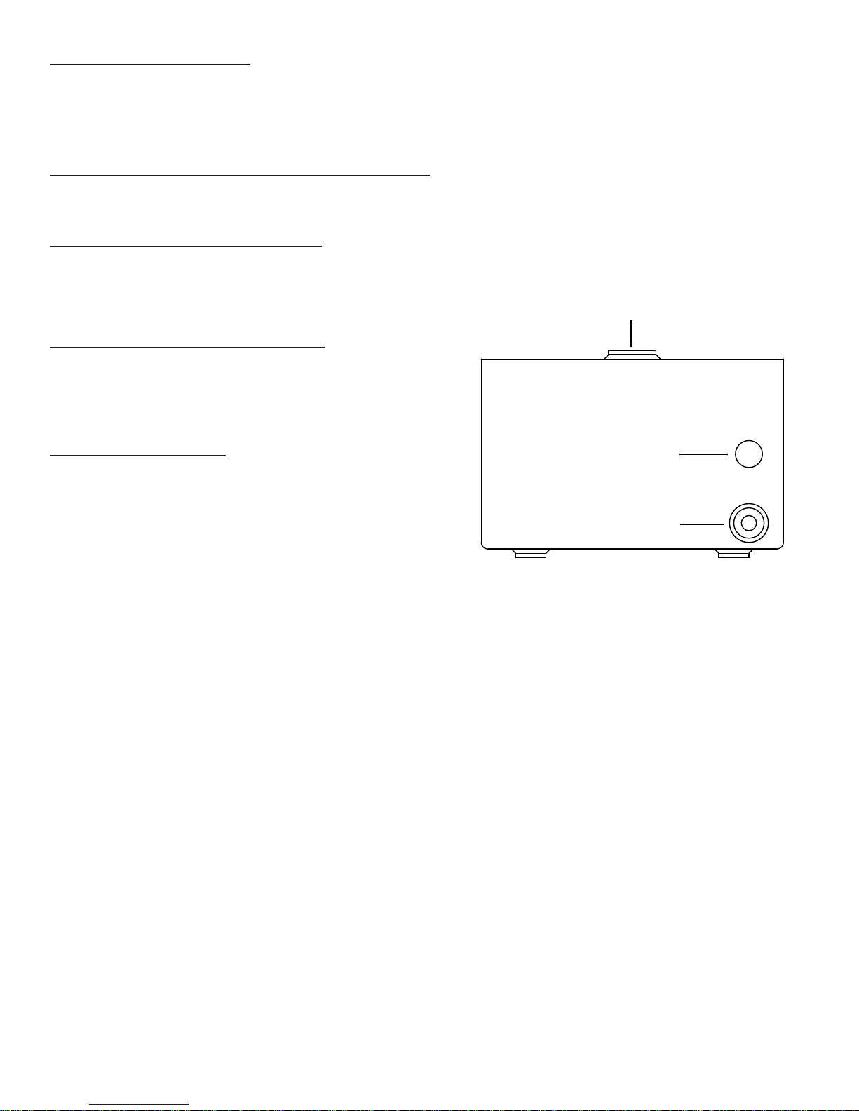
Oil Fill (1.5 - 10 Gal. Models)
6.3 FLUSH THE PUMP
If you suspect your pump has been contaminated or discover
sludge or other deposits on internal components, you should
thoroughly ush the pump. Remove the old oil from the reservoir,
then thoroughly clean the reservoir and rell with a clean,
nonammable ushing oil. Reassemble the pump and motor to the
reservoir.
Run the pump in no load condition for 1 or 2 minutes maximum.
Unplug the pump and remove the motor and pump assembly again.
Now drain the ushing oil and re-clean the inside of the reservoir.
(Make sure ushing uid is also drained from pump assembly). Rell
the reservoir with TorcUP hydraulic oil and reassemble the pump.
Sight Gauge
Drain Plug (1.5 - 10 Gal.)
www.torcup.com
Page 11

••• 9 •••
7.0 TROUBLESHOOTING
PROBLEM CAUSE-SOLUTION
Sporadic Tool Action: • Air in the hydraulic system. Bleed the hydraulic circuit.
• Check reservoir oil level.
Motor Will Not Start: • Be sure power cord is not damaged.
• Check for tripped circuit breaker; be sure breaker is of adequate
size.
• Have motor checked for proper operation.
• Have qualied electrician inspect for loose or faulty wiring or switch.
Noisy Operation: • Air in system.
• Be sure the oil reservoir is lled to normal level.
• Check all points where air might leak into system.
• Clogged or blocked intake screen.
Pump Oil is Over Heating: • Inspect for high pressure leakage at the pump (leaking at plug or
relief valve).
• Oil level is low. Fill reservoir to normal level, or retrot the pump with
larger reservoir or heat exchanger.
Pump Runs But Will Not Pump Oil: • Pump is not primed. Run pump a few minutes tipping from side to
side.
• Inspect to make sure that external adjustable relief valve is set
properly.
• Defective control valve, take to nearest TorcUP Authorized Service
Center for repair.
• Incorrect motor rotation, take to nearest TorcUP Authorized Service
Center for repair.
• Check to make sure the intake screen is not clogged. Clean if
needed.
• Check oil reservoir is low. Fill as needed.
• Oil viscosity is too high. Replace with TorcUP oil.
www.torcup.com
Page 12
Material Safety Data Sheet MSDS No. HydOil001
RYKON® Oil MV
1.0 CHEMICAL PRODUCT AND COMPANY IDENTIFICATION
PRODUCT NAME: RYKON® OIL MV
MANUFACTURER/SUPPLIER: EMERGENCY HEALTH INFORMATION:
Amoco Oil Company 1 (800) 447-8735
200 East Randolph Drive EMERGENCY SPILL INFORMATION:
Chicago, IL 60601 1 (800) 424-9300 CHEMTREC (USA)
OTHER PRODUCT SAFETY INFORMATION:
(312) 856-3907
2.0 COMPOSITION/INFORMATION ON INGREDIENTS
COMPONENT CAS# RANGE % BY WEIGHT
Solvent refined heavy
64741-88-4 80-100
paraffinic distillate
(See section 8.0 “Exposure Controls/Personal Protection” for exposure guidelines)
3.0 HAZARDS IDENTIFICATION
EMERGENCY OVERVIEW: This product has been evaluated and does not require any
hazard waning on the label under OSHA criteria.
POTENTIAL HEALTH EFFECTS:
EYE CONTACT: No significant health hazards identified.
SKIN CONTACT: Prolonged or repeated contact may produce some skin irritation.
High-pressure equipment can inject this product through the skin and cause severe
damage.
INHALATION: No significant health hazards identified.
INGESTION: No significant health hazards identified.
HMIS CODE: (Health:0) (Flammablility:1) (Reactivity:0)
NFPA CODE: (Health:0) (Flammablility:1) (Reactivity:0)
4.0 FIRST AID MEASURES
EYE: Flush eyes with plenty of water.
SKIN: Wash exposed skin with soap and water. Get medical attention if irritation develops.
Get immediate medical attention following injection injuries.
INHALATION: If adverse effects occur, remove to uncontaminated area. Get medical
attention.
INGESTION:
Page 13
5.0 FIRE FIGHTING MEASURES
FLASHPOINT: 383oF (195oC) (Cleveland open cup)
UEL: Not Determined
LEL: Not Determined
AUTOIGNITION TEMPERATURE: Not Determined
FLAMMABILITY CLASSIFICATION: Not Flammable.
EXTINGUISHING MEDIA: Agents approved for Class B hazards (e.g. dry chemical, carbon
dioxide, foam, steam) or water fog.
UNUSUAL FIRE AND EXPLOSION HAZARDS: None Identified.
FIRE-FIGHTING EQUIMENT: Firefighters should wear full bunker gear, including a positive
pressure self-contained breathing apparatus.
HAZARDOUS COMBUSTION PRODUCTS: Incomplete burning can produce carbon
monoxide and/or carbon dioxide and other harmful products.
6.0 ACCIDENTAL RELEASE MEASURES
Prevent spreading by diking, ditching, or absorbing on inert materials. Keep out of sewers
and waterways.
7.0 HANDLING AND STORAGE
HANDLING: No Special Requirements
STORAGE: No Special Requirements
8.0 EXPOSURE CONTROLS/PERSONAL PROTECTION
EYE: None required, however, use of eye protection is good industrial practice.
SKIN: Wear protective gloves if prolonged or repeated contact is expected.
INHALATION: None required, however, use of adequate ventilation is good industrial
practice
ENGINEERING CONTROLS: Control airborne concentrations below the exposure
guidelines
EXPOSURE GUIDELINES:
COMPONENT CAS# EXPOSURE LIMITS
Solvent refined heavy
paraffinic distillate
64741-88-4 OSHA PEL: 5mg/m3 (oil mist) (1989) (1971)
ACGIH TLV-TWA: 5 mg/m
ACGIH TLV-STEL: 10 mg/m
3
(oil mist)
3
(oil mist)
Page 14

9.0 CHEMICAL AND PHYSICAL PROPERTIES
APPEARANCE AND ODOR:
pH:
VAPOR PRESSURE:
VAPOR DENSITY:
BOILING POINT:
MELTING POINT:
SOLUBILITY IN WATER:
SPECIFIC GRAVITY (WATER = 1)
VISCOSITY:
POUR POINT:
VISCOSITY INDEX:
Oily liquid. Pale yellow
Not Determined
Not Determined
Not Determined
Not Determined
Not Determined
Negligible, below 0.1%
0.87
32.4 – 39.66cSt at 40
o
C
-40oF (-40oC) (maximum)
95 Minimum
10.0 STABILITY AND REACTIVITY
STABILITY: Stable
CONDITIONS TO AVOID: None identified
MATERIALS TO AVOID: Avoid chlorine, fluorine, and other strong oxidizers
HAZARDOUS DECOMPOSITION: None identified
HAZARDOUS POLYMERIZATION: Will not occur.
11.0 TOXICOLOGICAL INFORMATION
ACUTE TOXICITY DATA:
EYE IRRITATION: Testing not conducted. See other toxicity data.
SKIN IRRITATION: Testing not conducted. See other toxicity data
DERMAL LD50: Testing not conducted. See other toxicity data
ORAL LD50: Testing not conducted. See other toxicity data
INHALATION LC50: Testing not conducted. See other toxicity data
OTHER TOXICITY DATA:
Specific toxicity test have not been conducted on this product. Our hazard evaluation
is based on information from similar products, the ingredients, technical literature,
and/or professional experience.
No component of this product present at levels greater than 0.1% is identified as a
carcinogen by the US National Toxicology Program, the US Occupational Safety and
Health Act, or the International Agency on Research on Cancer (IARC).
12.0 ECOLOGICAL INFORMATION
Ecological testing has not been conducted on this product.
Page 15

13.0 DISPOSAL INFORMATION
Disposal must be in accordance with applicable federal, state, or local regulations. Enclosed
– controlled incineration is recommended unless directed otherwise by applicable ordinances.
This material may be amenable to recycling.
Since the emptied containers retain product residue, follow label warnings even after
container is emptied.
14.0 TRANSPORTATION INFORMATION
US DEPT OF TRANSPORTATION
Shipping Name: Not Regulated
INTERNATIONAL INFORMATION
Sea (IMO/IMDG)
Shipping Name: Not Determined
Air (ICA/IATA)
Shipping Name: Not Determined
European Road/Rail (ADR/RID)
Shipping Name: Not Determined
Canadian Transportation of Dangerous Goods
Shipping Name: Not Determined
15.0 REGULATORY INFORMATION
CERCLA SECTIONS 102A/103 HAZARDOUS SUBSTANCES (40 CFR PART 302.4): This
product is not reportable under 40 CFR Part 302.4
SARA TITLE III SECTION 302 EXTREMELY HAZARDOUS SUBSTANCES (40 CFR PART 355): This product
is not regulated under Section 302 of SARA and 40 CFR Part 355
SARA TITLE III SECTIONS 311/312 HAZARDOUS CATEGORIZATION (40 CFR PART 370): This product is
not regulated under SARA Title III Section 311/312
SARA TITLE III SECTION 313 (40 CFR PART 372): This product is not regulated under Section 313 of SARA
and 40 CFR Part 372
US INVENTORY (TSCA): Listed on inventory
This product contains n-methyl pyrrolidone (CAS 872-50-4) which is currently undergoing review and
testing under TSCA Section 4. Notification to the US EPA Office of Toxic Substances is required prior to
export of this material from the United States.
OSHA HAZARD COMMUNICATION STANDARD: Contains a component listed by OSHA. Contains a
component listed by ACGIH
EC INVENTORY (EINECS/ELINCS): Not Determined
JAPAN INVENTORY (MITI): Not Determined
AUSTRALIA INVENTORY (AICS): Not Determined
KOREA INVENTORY (DSL): Not Determined
CANADA INVENTORY (DSL): Not Determined
PHILIPPINE INVENTORY (PICCS): Not Determined
FOOD CONTACT STATUS:
USDA: H2 Status. This product is acceptable to the USDA for use as a lubricant in official meat and
poultry establishments provided there is no possibility of the lubricant or lubricated part contacting
edible products.
Page 16

16.0 OTHER INFORMATION
Prepared by
Environmental Health and Safety Department Issued: September 20, 1993
This Material Safety Data Sheet conforms to the requirements of ANSI z400.1
This material safety data sheet and the information it contains are offered to you in good faith
as accurate. We have reviewed any information contained in this data sheet, which we
received from sources outside our company. We believe the information to be correct, but
cannot guarantee its accuracy or completeness. Health and safety precautions in this data
sheet may not be adequate for all individuals and/or situations. It is the user’s obligation to
evaluate and use this product safely and to comply with all applicable laws and regulations.
No statement made in this data sheet shall be construed as a permission or recommendation
for the use of any product in a manner that might infringe existing patents. Not warranty is
made, either express or implied.
Page 17
L
8
V
0
p
all
3
21st Century Bolting Tool Technology
1025 Conroy Place, Easton,
PA, 18040 U.S.A.
Phone: 610-250-5800
[email protected]* www.torcup.com
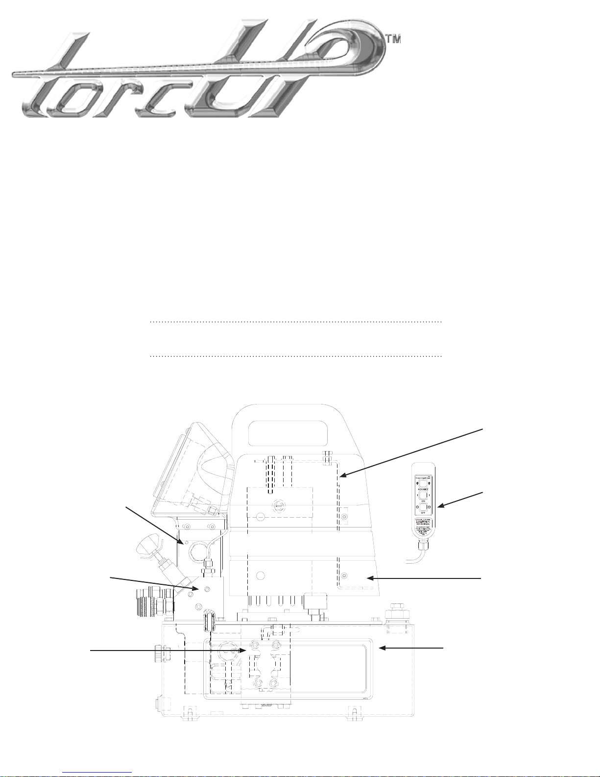
This illustration is for reference purposes only. The
appearance of your unit may differ from the unit shown.
EP1000 SERIES
TORQUE POWER PUMP
PARTS IDENTIFICAT ION MANUA
ev. - A
Date - 10/0
ectrical Brackets Wiring
iagrams - pg. 11-12
alve Sub-Assemblies
pg. 8-9
anifold Sub-Assembly
pg. 1
ump Sub-Assemblies
and Sub-Com
pg. 5-7
onents
Pendants - pg. 11-12
ommon Components
in
orcUP pumps - pg. 3-4
eservoirs - pg. 1
Page 18
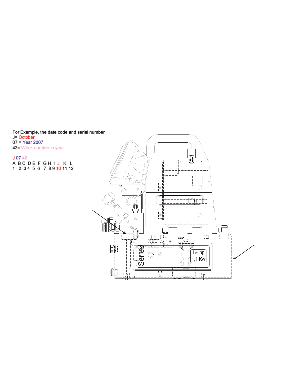
EP1000 Torque Wrench
How to Identify Parts
Power Pump
for Your Model.
MODEL NUMBER & DATE CODE LOCATION
DATE CODE COVER PLATE
STAMPING LOCATION
MODEL DECAL
PLACEMENT
Page 19
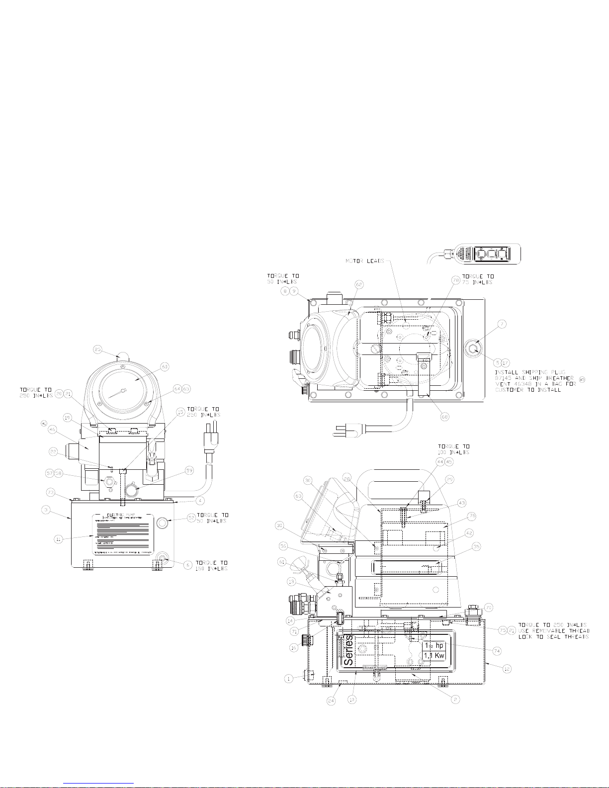
EP1000 Torque Wrench
Common components
Power Pump
NOTE: This illustration is for reference
only. The appearance of your unit
may dier from unit shown.
used in pumps
Page 20
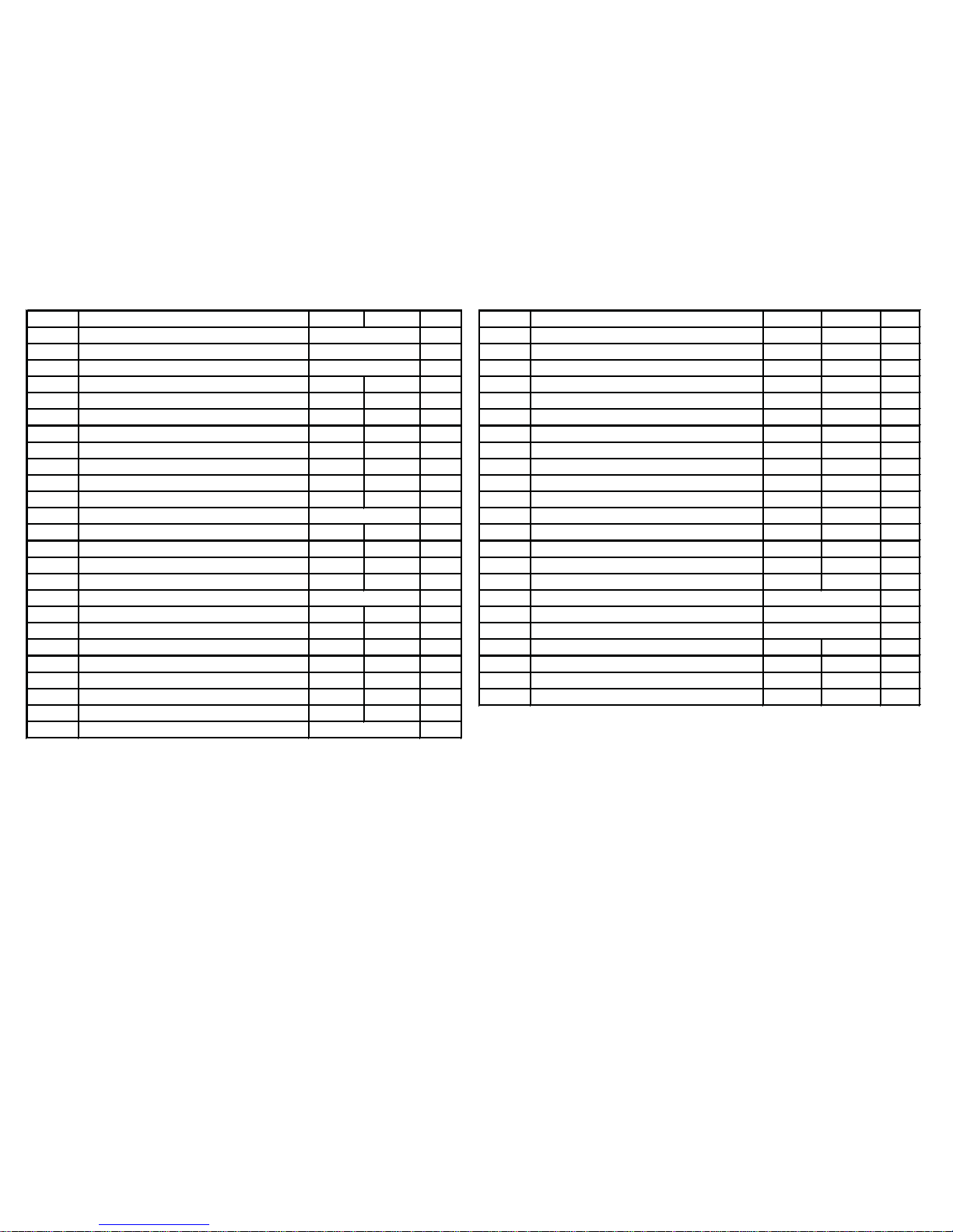
EP1000 Torque Wrench
Common components
Power Pump
ITEM # DESCRIPTION PART # PART # QTY. ITEM # DESCRIPTION PART # PART # QTY.
02 PUMP ASM. 1.00 29 HEAVY HEX JAM NUT 1/4-20 69234 69234 2.00
03 RESERVOIR 1.00 30 BHCS 10-24 x 3/8 LG 69236 69236 4.00
04 RESERVOIR GASKET 1.00 30 BHCS 10-24 x 3/8 LG 69236 69236 4.00
05 BREATHER VENT 3/8" NPT 46348 46348 1.00 35 SIMPLEX DECAL 5.71" x 1.15" 46355 46355 2.00
06 PIPE PLUG 1/4" W/ COATING 46510 46510 1.00 37 QUICK DISCON. FLAG BLUE 44491 44491 2.00
07 SAE #12 HEX PLUG WITH PT 46118 46118 1.00 42 HOLE PLUG 1/4" 46405 46405 4.00
08 HHC
09 SEALING WASHER 65892 65892 14.00 44 HHCS 1/4-20 X 1.50 84417 87260 2.00
10 G5 RES
11 LABEL SAFE USE ELEC 68068 68068 1.00 46 COIL 115V WITH DIN CONNECTOR 46294 46324 1.00
12 BLANK DECAL 3 X 4 87305 87305 1.00 52 SIGHT GAUGE 46009 46009 1.00
13 MANIFOLD ASM. 1.00 57 1/4 IN NIPPLE 4100067 4100067 1.00
14 VALVE GASKET 69242 6
15 SHCS 3/8-16 X 2 3/4 99921 99921 3.00 59 1/4" SELF-LOCKING COUPLER 45765 45765 1.00
16 ADAPTER ASSY. 68963 68963 1.00 62 GAUGE SHROUD ASSEMBLY 46474 46474 1.00
17 HEX PIPE PLUG 3/8" W/ COATING 46513 46513 1.00 68 VELCRO STRAP 1x14 46310 46310 1.00
19 VALVE ASM. 2P/4W 1.00 70 GASKET-MOTOR 1.00
20 SHCS 3/8-16 X 3 1/2 88363 88363 4.00 71 PUMP GASKET G5 1.00
21 LOCK WASHER 3/8 93943 93943 2.00 73 COVER PLATE 1.00
21 LOCK WASHER 3/8 93943 93943 4.00 74 PIN,DOW EL 3/16 1" LONG 69026 69026 1.00
22 ROLL PIN 1/8 X 3/8 LG 561604 561604 1.00 75 SHCS 3/8-16 X 1 93594 93594 2.00
24 MAGNET 66021 66021 1.00 76 1 1/2HP, PM MOTOR 68376 68403 1.00
25 MOTOR SHROUD W / HANDLE 45534 45534 1.00 78 FHCS 1/4-28 x 0.50 LONG 46279 46279 4.00
27 DECAL OVERLAY 46539 46539 1.00
28 BRACKET ASM 1.00
S 1/4-20 X .75 PLT 65891 65891 14.00 43 SPACER 1" 69353 69759 2.00
ERVOIR DECAL 46052 46052 2.00 45 W ASHER 1/4" SS 88429 88429 2.00
SEE PAGE 5-7
SEE PAGE 12
*
SEE PAGE 9
9242 1.00 58 1/4" NIPPLE CT210 CT210 1.00
SEE PAGE 9
SEE PAGE 10-11
used in pumps
*
*
SEE PAGE 12
NOTES :
REBUILD KIT ( * = COMPONENTS) -- PART # 54488
Page 21
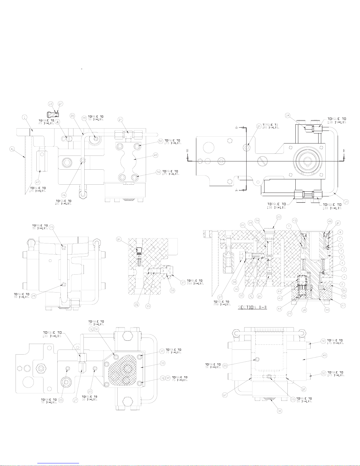
EP1000 Torque Wrench
Power Pump
(46335) PUMP ASM.
Sub Pump Assembly
Page 22
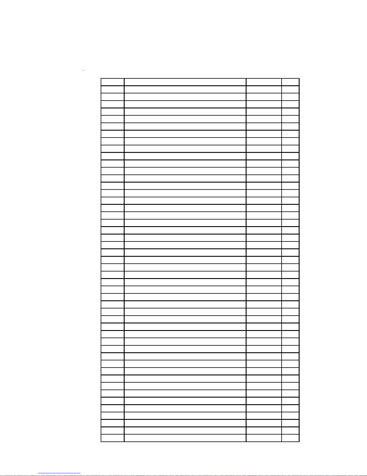
EP1000 Torque Wrench
Power Pump
(46335) PUMP ASM.
ITEM # DESCRIPTION PART # QTY.
01 PUMP BODY G5 45750 1.00
02 BEARING ROLLER 5/8x13/16x5/8 WIDE 68360 1.00
03 THRUST BEARING 66033 1.00
04 THRUST WASHER 66474 2.00
05 ECCENTRIC SHAFT ASM 5/8" G5
06 THRUST BEARING 66106 1.00
07 THRUST WASHER 66108 2.00
08 ECCENTRIC SHAFT ADAPTER G5 45908 1.00
09 O-RING 1 3/4 X 1 7/8 * 1.00
10 RETAINING RING 68978 1.00
11 POW'R BUD DUMP PLUG 43283 1.00
12 O-RING 3/16X5/16 * 3.00
13 BACKUP WASHER 56080087 1.00
14 MALE TEE 1/8" PIPE TO 1
15 PIPE PLUG 1/4" FLUSH W/ COATING 46509 1.00
16 UNLOADING PISTON ASSEMBLY
17 MALE ELBOW 1/4" TUBE 1/4" PIPE 45929 1.00
18 BALL 1/8" 90906 3.00
19 G3 PISTON BLOCK TUBE 45420 1.00
20 OUTLET TUBE PISTON BLOCK 45815 1.00
21 BALL 5/16" 91701 3.00
22 UNLOADING SPRING 43671 1.00
23 ADJUSTING SCREW G5 45903 1.00
24 O-RING 5/8X3/4 URETH * 1.00
25 PIPE PLUG FLUSH 1/16 W/ COATING 40049 7.00
26 WEAR PLATE G5 45909 1.00
27 BOT
28 GEAR PUMP 0.281 45824 2.00
29 SHAFT-IDLER 68850 1.00
30 SCREEN * 1.00
31 TUBE-GUIDE .11 68894 2.00
32 SHCS 1/4-28 X 1 3/4 68255 5.00
33 PLATE-SCREEN MTG. 68927 1.00
34 MALE ELBOW 1/8 PIPE 69354 1.00
35 SPRING 68225 2.00
36 ROLL PIN 1/8 X 3/4 LONG 97782 1.00
37 BALL STOP G5 45904 2.00
38 GASKET 29/64 X 5/8 * 2.00
39 SPRING CAP UNLOADING VALVE 43673 1.00
41 TUBE RETURN 68569 1.00
43 BEARING ROLLER 1 1/4x1 1/2x3/4 WIDE 6603
44 BEARING ROLLER 1/2x11/16x1/2 WIDE 68891 3.00
45 RING-RETAINING 68892 1.00
46 PIPE PLUG 1/8" FLUSH W/ COATING 46508 1.00
47 CART REL. VAL. ASSEMBLY 66220 1.00
48 SHAFT SEAL G5 * 1.00
49 PISTON BLOCK ASM. 0.255 G5
50 SHCS 5/16-24 X 1.75 69392 8.00
TOM PLATE 9/32" G5 45900 1.00
Sub Pump Assembly
SEE PAGE 7 1.00
/4" TUBE 45426 1.00
SEE PAGE 7 2.00
0 1.00
SEE PAGE 7 2.00
REBUILD KIT ( * = COMPONENTS) -- PART # 54488
Page 23
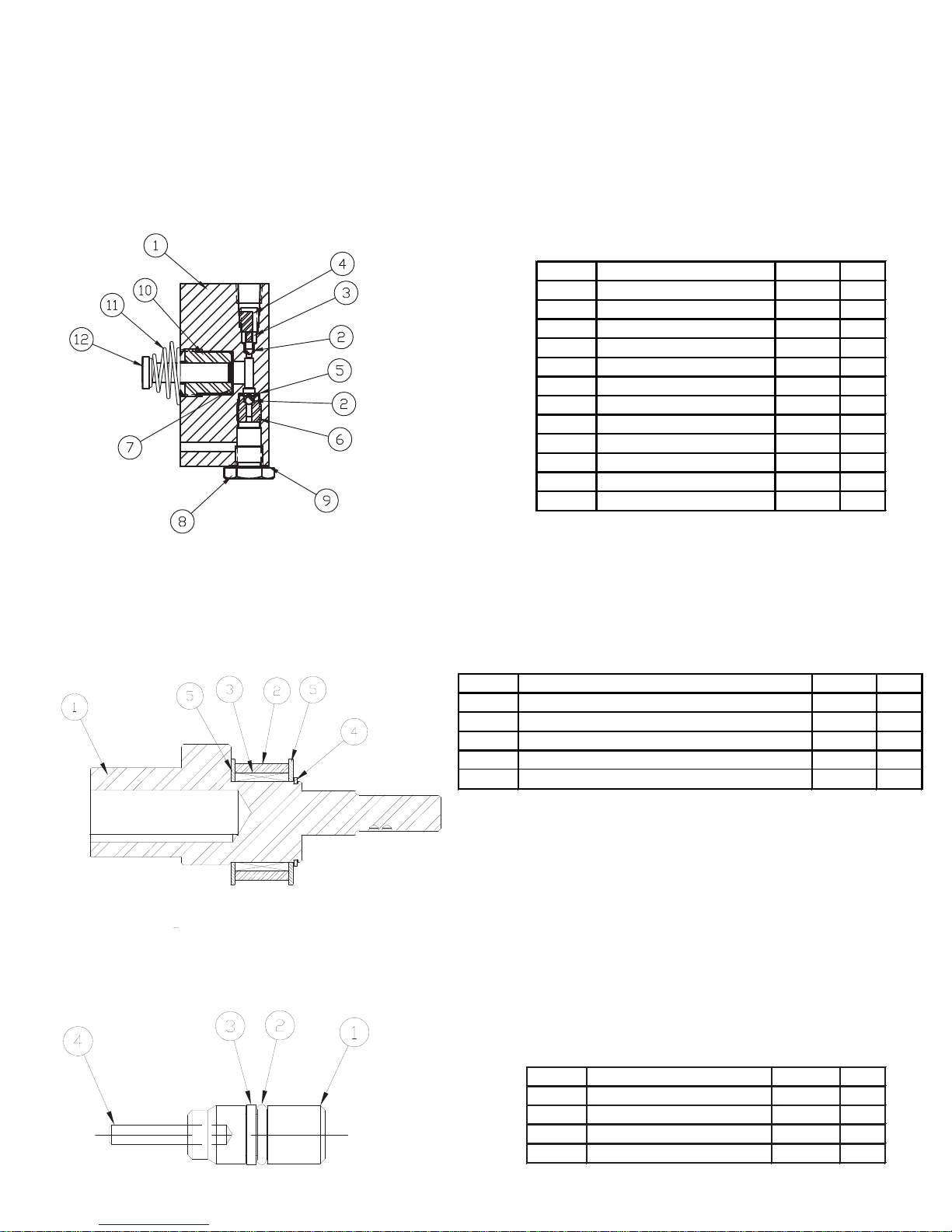
EP1000 Torque Wrench
Sub Component
Power Pump
(46336) PISTON BLK ASM.
Assemblies
ITEM # DESCRIPTION PART # QTY.
01 GEN II PISTON BLOCK 45539 1.00
02 BALL 1/8" 90906 2.00
03 SPRING 66042 1.00
04 BALL STOP 68810 1.00
05 BALL RETAINER 66043 1.00
06 INTAKE SEAT 66046 1.00
07 GASKET 25/64X19/32 1.00
08 PLUG PISTON BLOCK 68825 1.00
09 GASKET 29/64 X 5/8 1.00
10 ADAPTOR .255 DIA. 68909 1.00
11 SPRING, PISTON 68340 1.00
12 PISTON .255 DIA. 68222 1.00
*
*
(45820) ECCEMTRIC SHAFT ASM.
(43766) UNLOADING PISTON ASM.
ITEM # DESCRIPTION PART # QTY.
01 ECCENTRIC SHAFT 5/8" 45819 1.00
02 ECCENTRIC RING 45907 1.00
03 ROLL BEARING 1 1/8x1 3/8x3/4 WIDE 45926 1.00
04 RETAINING RING EXTERNAL 1 1/8" 45931 1.00
05 THRUST WASHER 68026 2.00
REBUILD KIT ( * = COMPONENTS) -- PART # 54488
ITEM # DESCRITPION PART # QTY.
01 UNLOAD PISTON 43765 1.00
02 O RING 1/4X3/8 1.00
03 BACK-UP WASHER TEF 43768 1.00
04 DOWEL PIN 1/8X3/4 LG 43686 1.00
*
Page 24
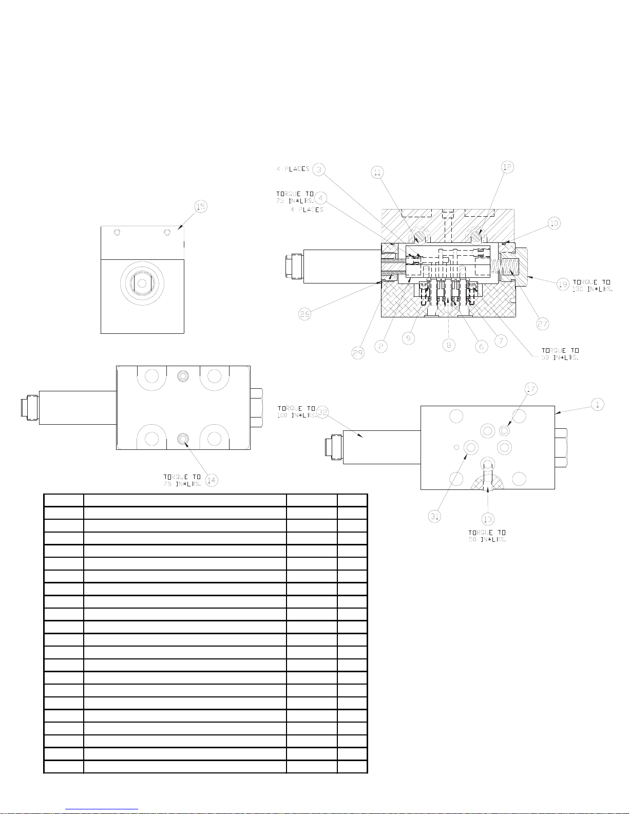
EP1000 Torque Wrench
Valve Sub Assemblies
Power Pump
(46291) 3 & 4 WAY SOLENOID VALVE 115V. / 230V.
ITEM # DESCRIPTION PART # QTY.
01 BODY-VALVE 68708 1.00
02 SLIDER ADV/RET ONLY 44328 1.00
03 BALL 3/16" 90548 4.00
04 SET SCREW 1/4-28 X 1/4 CUP 40254 4.00
06 O-RING 7/32X11/32 * 3.00
07 BACK UP WASHER * 3.00
08 SHEAR SEAL 68383 3.00
09 SPRING 68384 3.00
10 O-RING 2 5/8 X 2 3/4 * 1.00
11 BEARING ROLLER 5/16x1/2x5/16 WIDE 68385 4.00
12 PIN BEARING 68390 2.00
13 PIPE PLUG FLUSH 1/16 W/ COATING 40049 1.00
14 SHCS #10-32 X 1" LG PLATED 68264 2.00
15 VALVE TOP PLATE MACHINED 46272 1.00
7 O-RING 3/16X5/16 * 1.00
1
19 VALVE PLUG 2 POSITION SLIDER 46271 1.00
26 O-RING SAE PORT #10 * 2.00
27 SPRING 68711 1.00
29 SPACER VALVE SLIDER 46418 1.00
31 O-RING 5/16X7/16 URE * 4.00
32 PUSHER-SOLENOID 68729 1.00
PACKING KIT 3 & 4 WAY SOLENOID VALVE
(* = COMPONENTS) -- PART #54491
Page 25
EP1000 Torque Wrench
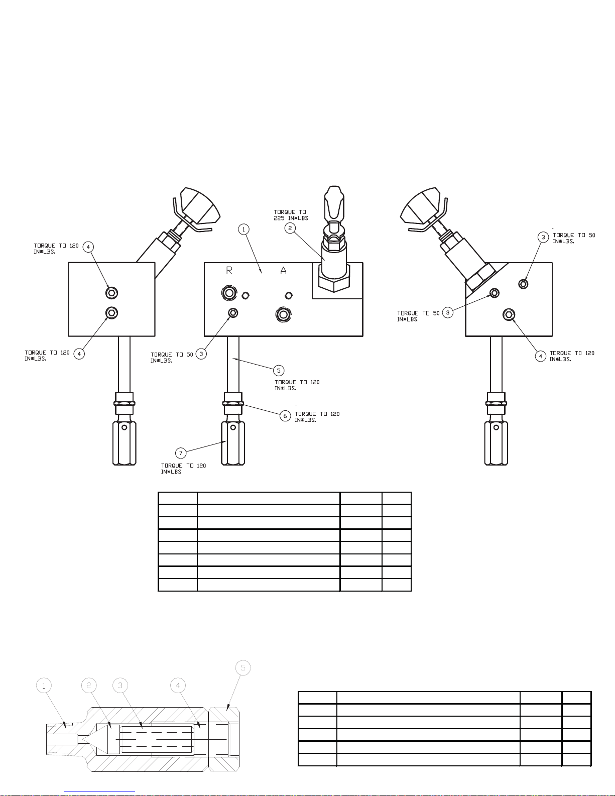
Power Pump
(46292) MANIFOLD ASM.
Manifold Assembly
ITEM # DESCRIPTION PART # QTY.
01 VALVE MANIFOLD 46270 1.00
02 CARTRIDGE RELIEF VALVE 45423 1.00
03 1/16 PIPE PLUG-FLUSH 40049 3.00
04 PIPE PLUG 1/8" FLUSH 81093 3.00
05 PIPE NIPPLE 1/8 NPT 68917 1.00
06 PIPE COUPLING 1/8 68918 1.00
07 INT.RELIEF ASM HF 68999 1.00
(68999) INT. RELIEF ASM.
ITEM # DESCRIPTION PART # QTY.
01 CARTRIDGE 66096 1.00
02 CONE REL VLVE 66086 1.00
03 POPPET RELIEF SPRING 44641 1.00
04 RELIEF VALVE ADJUSTING SCREW 66083 1.00
05 HEX NUT 7/16-20 68920 1.00
Page 26
EP1000 Torque Wrench
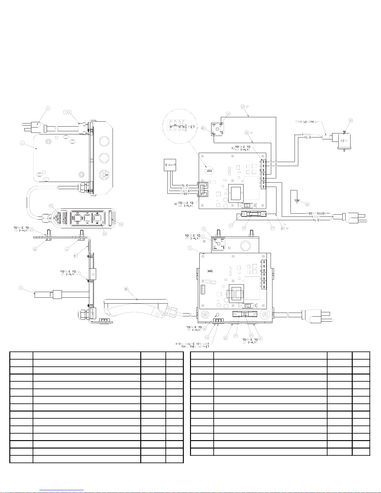
Bracket Sub
Power Pump
(46281) BRACKET SUB ASM. 115V.
Assemblies
ITEM # DESCRIPTION PART # QTY. ITEM # DESCRIPTION PART # QTY.
01 MOUNTING BRACKET G3/G5 46233 1.00 15 RING TERMINAL 1/4" 69917 1.00
02 PLUG AND CORD ASSY 68595 1.00 16 SHCS #10-32X1/4" LG PLATED 45175 1.00
03 HOSE CLAMP 69235 1.00 17 GROMMET 7/8" HOLE 69855 1.00
04 CIRCUIT BOARD BASIC 46196 1.00 18 PENDANT ASSEMBLY BASIC 46220 1.00
05 BRIDGE RECTIFIER 25A 68623 1.00 19 MEMBRANE SWITCH LABEL PET * 1.00
06 SHCS #10-32 X 1/2 66805 1.00 20 MOLDED DIN CONNECTOR W/ CORD 46327 1.00
07 FITTING,CORD L-TIGHT 68375 1.0
08 LOCKNUT 1/2 INCH 85510 1.00 22 DECAL PENDANT INSTRUCTION * 1.00
09 MACHINE SCREW W/ LOCK WASH 46248 5.00 23 SIMPLEX DECAL 1.25" x 0.25" * 1.00
10 HOLE PLUG 7/8" 69652 2.00 24 FUSE HOLDER 30 AMP 46481 1.00
11 HHCS 1/4-20 X .75 PLT 65891 2.00 25 FUSE 25 AMP 46482 1.00
12 HEX NUT 1/4-20 PLATD 93849 2.00 26 SHCS #6-32 x 1/4 LONG 46506 1.00
13 WIRE #14 BLACK 68261B 2.00 27 SPADE TERMINAL 68116 2.00
14 QUICK DISCON. FL
AG BLUE 44491 2.00
0 21 PUSH THRU BUSHING 46420 1.00
PENDANT DECAL KIT (* = COMPONENTS) -- PART # 54489
Page 27
EP1000 Torque Wrench
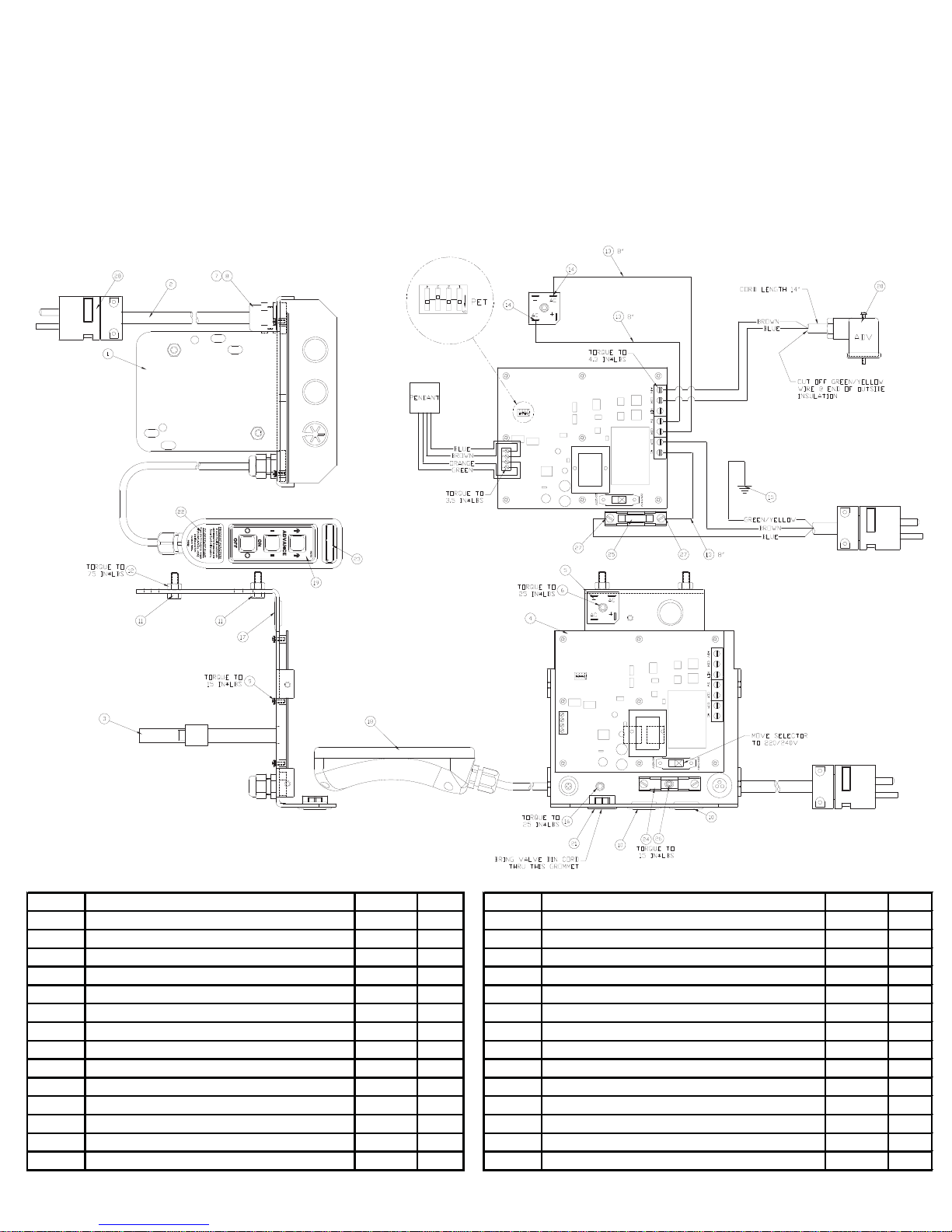
Bracket Sub
Power Pump
(46289) BRACKET SUB ASM. 230V.
Assemblies
ITEM # DESCRIPTION PART # QTY. ITEM # DESCRIPTION PART # QTY.
01 MOUNTING BRACKET 46233 1.00 15 RING TERMINAL 1/4" 69917 1.00
02 POWER CORD 14-3 IEC 69604R 72.00 16 SHCS #10-32X1/4" LG PLATED 45175 1.00
03 HOSE CLAMP 69235 1.00 17 GROMMET 7/8" HOLE 69855 1.00
04 CIRCUIT BOARD BASIC 46196 1.00 18 PENDANT ASSEMBLY BASIC 46220 1.00
05 BRIDGE RECTIFIER 25A 68623 1.00 19 MEMBRANE SWITCH LABEL PET * 1.00
06 SHCS #10-32 X 1/2 66805 1.00 20 MOLDED DIN CONNECTOR W/ CORD 46327 1.00
07 FITTING,CORD L-TIGHT 68375 1.00 2
08 LOCKNUT 1/2 INCH 85510 1.00 22 DECAL PENDANT INSTRUCTION * 1.00
09 MACHINE SCREW W/ LOCK WASH 46248 5.00 23 SIMPLEX DECAL 1.25" x 0.25" * 1.00
10 HOLE PLUG 7/8" 69652 2.00 24 FUSE HOLDER 30 AMP 46481 1.00
11 HHCS 1/4-20 X .75 PLT 65891 2.00 25 FUSE 25 AMP 46482 1.00
12 HEX NUT 1/4-20 PLATD 93849 2.00 26 SHCS #6-32 x 1/4 LONG 46506 1.00
13 WIRE #14 BLACK 68261B 2.00 27 SPADE TERMINAL 68116 2.00
14 QUICK DISCON. FLAG
BLUE 44491 2.00 28 PLUG 20 AMPS-250V 87093 1.00
1 PUSH THRU BUSHING 46420 1.00
PENDANT DECAL KIT (* = COMPONENTS) -- PART # 54489
Page 28
EP1000 Torque Wrench
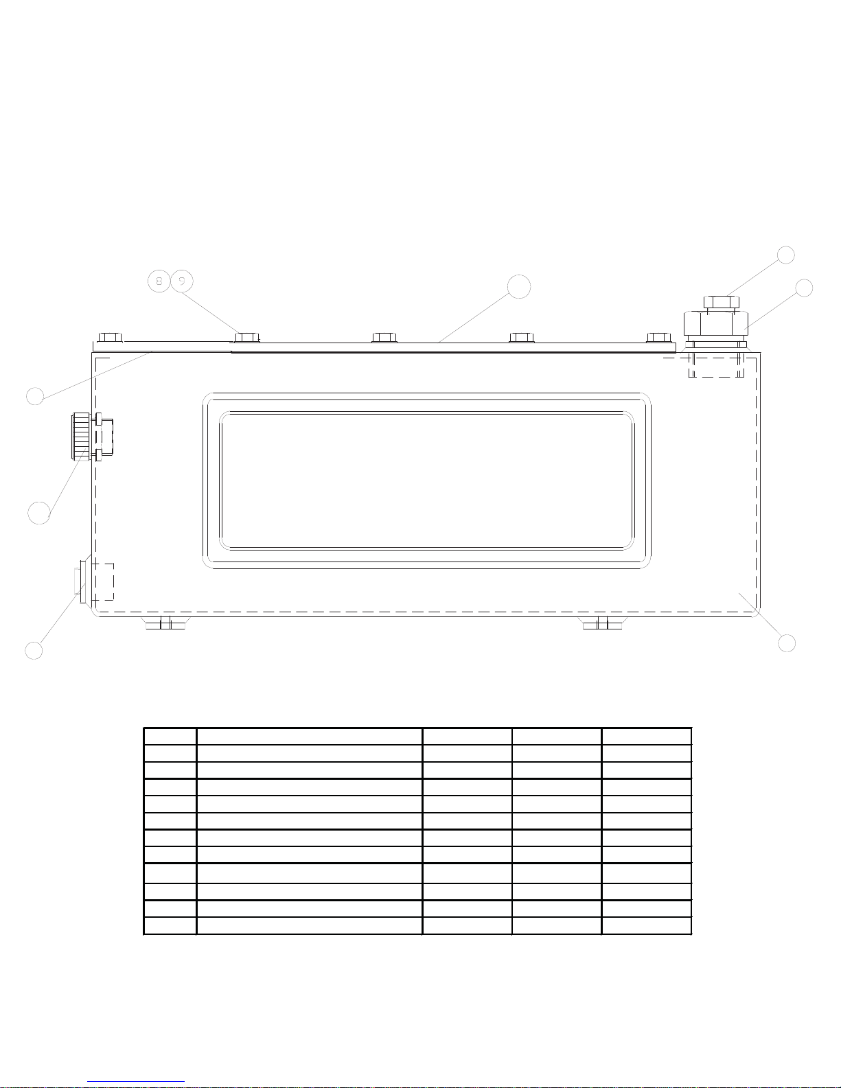
Power Pump
(45996P) 1.5 GALLON RESERVIOR
(46213P) 2.5 GALLON RESERVIOR
Reservoirs
5
4
52
6
7 3
1.5 GALLON RESERVOIR
NOTE: THIS ILLUSTRATION IS FOR REFERENCE ONLY.
THE APPEARANCE OF YOUR UNIT MAY DIFFER
FROM UNIT SHOWN.
7
3
ITEM # DESCRIPTION 1.5 GALLON 2.5 GALLON QTY.
03 RESERVOIR 45996P 46213P 1.00
04 RESERVOIR GASKET 85469 85469 1.00
05 BREATHER VENT 3/8" NPT 46348 46348 1.00
06 1/4 SOC PIPE PLUG 93950 93950 1.00
07 SAE #12 HEX PLUG W ITH PORT 46118 46118 1.00
08 HHCS 1/4-20 x 3/4 LG PLATED 65891 65891 14.00
09 SEALING WASHER 65892 65892 14.00
52 SIGHT GAUGE 46009 46009 1.00
73 COVER PLATE 46334 46334 1.00
NS PIPE COUPLING 1/4 N/A N/A 1.00
NS NIPPLE N/A N/A 1.00
NS = NOT SHOWN
NOTE: ALL RESERVOIRS ARE POWDER COATED BLACK
Page 29
Page 30
T
21st Century Bolting Tool Technology
1025 Conroy Place, Easton,
PA, 18040 U.S.A.
Phone: 610-250-5800
[email protected]* www.torcup.com
orcUP PRODUCTS ARE WARRANTED TO BE FREE OF DEFECTS IN MATERIALS AND WORKMANSHIP UNDER NORMAL USE FOR AS LONG
S THE ORIGINAL PURCHASER OWNS THEM, SUBJECT TO THE GUIDELINES AND LIMITATIONS LISTED. THIS WARRANTY DOES NOT COVER :
NORMAL WEAR AND TEAR, COSMETIC ITEMS, ABUSE, OVERLOADING, ALTERATIONS. IMPROPER FLUID, OR USE IN A MANNER FOR WHICH
HEY ARE NOT INTENDED. IF THE CUSTOMER BELIEVES A PRODUCT IS DEFECTIVE, THE PRODUCT MUST BE DELIVERED, OR SHIPPED FREIGHT
REPAID, TO THE NEAREST TorcUP AUTHORIZED SERVICE CENTER FOR EVALUATION AND REPAIR.
Printed in the U.S.A.
 Loading...