


- 1 -
User Manual
Digital Video Recorder
CDVR-0402U

- 2 -
NOTE : This equipment has been tested and found to comply with the limits for a Class A digital device,
pursuant to part 15 of the FCC Rules. These limits are designed to provide reasonable protection against
harmful interference when the equipment is operated in a commercial environment. This equipment
generates, uses, and can radiate radio frequency energy and, if not installed and used in accordance with
the instruction manual, may cause harmful interference to radio communications. Operation of this
equipment in a residential area is likely to cause harmful interference in which case the user will be
required to correct the interference at his own expense.
FCC Compliance Statement
WARNING

- 3 -
1. Read Instructions
All the safety and operating instructions should be read before the product is operated.
2. Retain Instruction Manuals
The safety and operating instructions should be retained for future reference.
3. Heed Warnings
All warnings on the product and in the opera ting instructions should be adhered to.
4. Follow Instructions
All operating and use instructions shoul d be followed.
5. Cleaning
Unplug this product from the power outlet before cleaning.
Do not use liquid cleaners or aerosol cleaners. Use a damp cloth for cleaning.
6. Attachments
Do not use attachments not recommended by the product man ufacturer as they may cause hazards.
7. Water and Moisture
Do not use this product near water - for example, near a bath t ub, w ash bo wl, ki tchen sink, or laundry tub; in a wet
basement; or near a swimming pool; and the like.
8. Accessories
Do not place this product on an unstable cart, stand, tripod, bracket, or table. The product may fall, causing serious
injury to a child or adult, and serious damage to the pro duct.
9. Ventilation
Slots and openings in the cabinet are provided for ventilation and to ensure reli able oper ation of the product an d
to protect it from overheating, and these openings must not be blocked or covered. The openings should nev er be
blocked by placing the product on a be d, sofa, rug, or other similar surface. This product should not be placed in a
built-in installation such as a bookcase or rack unless proper ventilation is provided or the manufacturer’s
instructions have been adhered to.
10. Power Sources
This product should be operated on ly from the type of power source indicated on the marking label. If you are not
sure of the type of power supply to your home, consult your product dealer or local power company .
11. Power-Cord Protection
Power-supply cords should be routed so that they are not likely to be walked on or pinched by items placed
upon or against them, paying particular attention to car ds at plugs, convenience receptacles, and the point whe re
they exit from
12. Overloading
Do not overload wall outlets, extension cords, or integral convenience receptacle as this can result in a risk of
fire or electric shock.
13. Object and Liquid Entry
Never push objects of any kind into this product through openings as they may touch dangerous voltage
points or short-out parts that could result in a fire or electric shock. Nev er spill liquid of any kind on the product.
I
MPORTANT SAFETY INSTRUCTION
S

- 4 -
14. Damage Requiring Service
Unplug this product from the wall outlet and refer servicing to qualified service personnel under the following
conditions:
a) When the power-supply cord or plug is damaged.
b) If liquid has been spilled, or objects have fallen into the product.
c) If the product has been exposed to rain or water .
d) If the product does not operate normally by following the operating instructions. Adjust only those controls
that are covered by the operating instructions as an improper adjustment of other controls may result in
damage and will often require extensive work by a qualified technician to restore the product to its normal
operation.
e) If the product has been dropped or damaged in any way and
f) When the product exhibits a distinct change in performance - this indicates a need for service.
15. Replacement Parts
When replacement parts are required, be sure the service technician has used replacement parts specified by
the manufacturer or have the same characteristics as the original part. Unauthorized substitutio n s may result in
fire, electric shock, or other hazards.
16. Safety Check
Upon completion of any service or repairs to this product ask the service technician to perform safety checks
to determine that the product is in proper operating condition.
17. Heat
The product should be situated away from heat sources such as radiators, heat registers, stoves, or other
products (inclu ding am plifi ers) th at pro duce h eat the product.
18. Internal Fan
The internal fan rotates at high speed and may cause an accident.
19. Battery
Change the lithium battery after turning off the power of the product.
Check the polarity of the lithium battery while changing and change the lithium battery with the same type
which is in the product or with a similar type recommended by your vendor.
Dispose the lithium battery according to the instructions of the battery manufacturer .
There is danger of explosion when instructions are not followed.
20. Turning On/Off the DVR power.
Do not turn off the power by removal of the power plug.
T o turn off the power, click the power button from the front panel.
When the system stops abnormally , the power button might not work.
Click power button for 5 full seconds to turn power off.
Do not turn off the power unproperly or apply shock/vibration to unit while the hard disk is activating.
It may cause hard disk failure or loss of data.
Important Safety Instruction
s

- 5 -
FCC COMPLIANCE STATEMENT...........................................................................................
IMPORTANT SAFETY INSTRUCTIONS................................................................................
INDEX................................................................................................................................
1. INTRODUCTION AND INSTALLATION
DVR Components..........................................................................................................
Front Panel....................................................................................................................
Rear Panel.....................................................................................................................
Remote Controller.....................................................................................................
2. INSTALLATION
Installation of Hard Disk Drives...........................................................................................
Starting the DVR............................................................................................................
Log In & Log Out...........................................................................................................
USB Flash Drive............................................................................................................
3. CONFIGURATION
System Setup....................................................................................................................
Camera Setup....................................................................................................................
Motion Detection..................................................................................................
Masking...............................................................................................................
Record Setup.................................................................................................................
Record Schedule...........................................................................................................
Sensor Setup......................................................................................................................
Network Setup...................................................................................................................
Display Setup.....................................................................................................................
Backup & Format............................................................................................................
4. OPERATION
Monitoring.....................................................................................................................
Monitoring Screen................................................................................................
Freeze..................................................................................................................
Zoom...................................................................................................................
Sequence Display..................................................................................................
PTZ Control......................................................................................................................
Recording.................................................................................................................
Search(Playback)...........................................................................................................
DVR Search...........................................................................................................
USB Search..........................................................................................................
LOG Search.......................................................................................................................
Video Clip Copy............................................................................................................
Appendix : T echnical Specification........................................................................................
C
ONTENTS
2
3
5
6
7
8
9
10
11 12 13
14
17 18 18 19 21 22 24
27
28
29
29
29 29 30 30 31 32
32
36
37 40
41

- 6 -
The CDVR-0402 is a compact sized multiplexer digital video recorder developed to provides extremely long
recording capabilities with advanced recording and convenient search functions.
1.1. DVR Components
Check the package and contents for visible damage. If any components are damaged or missing, do not attempt
to use the unit, contact the supplier immediately. If the unit must be returned , it must be shipped in the original
packing box.
CDVR0402 Unit
Remote Controller
Power Cable
Program CD
Operation Manual
1. I
NTRODUCTION

- 7 -
1.2. Product Description
1.2.1. Front Panel
① POWER : Power On/Off
② PANIC : Recording On/Off of all channels at highest speed and quality .
③ Channel Indicator : Indicates which channels are operating
④ PREV : Move to previous category
⑤ NEXT : Move to next category
⑥ Remote Control Extension Cable Port
⑦ ESC : Return to previous mode
T urn On/Off the OSD
⑧ CH : Change channels
⑨
USB Flash Drive Port
⑩ D irectio n Keys & EN TER
(PTZ) : Move up, increase values, PTZ control(Tilt)
(PTZ) : Move down, decrease values, PTZ control (Tilt)
(PTZ) : Move left, PTZ Control(Pan)
(PTZ) : Move right, PTZ control(Pan)
ENTER : Enter MENU, Select/Enable a highlighted category/item.
Introduction
①
②
③
④
⑤
⑥
⑦ ⑧
⑨
⑩

- 8 -
1.2.2. Rear Panel
① Power Cable Connection. ( Does not support 110V~220V Free Volt)
② Power Switch.
- Select the correct voltage for your region.
③ Video Input Connectors
- Input connectors for video signals.
④ Audio Input Connectors
- Input connectors for audio signals.
⑤ VGA (Monitor) Port.
- Connection to PC monitor .
⑥ Video (Composite) Output Connector
- Output connector for video signals to analogue monitors.
⑦ Audio Output Connector
- Output connector for audio signals.
⑧ S-Video Connector
- Connection to S-Video jack.
⑨ Sensor and Alarm Output Connector
⑩ DIP Switch
Type OFF Position(Up) ON Position(Down)
NTSC /PAL NTSC PAL
COMPOSITE / SVIDEO COMPOSITE S-VIDEO
None -
TEST -
⑪ LAN Port
- Connection port for internet cable.
⑫ PTZ Serial Port
- Connection to PTZ camera.
PTZ Serial Com Port Serial Remote Control ETC
Pin No. Explanation Pin No. Explanation
Pin No.
Explanation Pin No. Explanation
1 nRS485 2 RX 6 RX 5 GND
9 RS485 3 TX
8
TX 4, 7 Not use
②
⑥ ⑦
⑧
⑨ ⑩
⑪ ⑫
Introduction
!
1
2 3
4 5 6
7
8
9
①
③
④
⑤

- 9 -
1.2.3. Remote Controller
OSD OSD On/Off during Monitoring/Full-screen Playback.
PANIC Panic Recording On/Off.
Numeral Keys Select channel or type in characters.
CAPTURE Capture video clip/image to external memory .
F/F Remove image distortion during frame by frame advance.
PREVIOUS Move to previous category .
NEXT Move to next category .
Direction Keys
Move cursor left/right/up/down.
PTZ control
MENU / ENTER
Enter Menu.
Select/Enable a highlighted category/item.
ESC Stop current operation or return to previous mode.
AUDIO Change audio channel during monitoring/playback.
LOG Enter Log Search mode.
PTZ Enter PTZ control mode.
SEARCH Enter Search(Playback) mode.
SETUP Enter Setup mode.
PAUSE
Pause during playback.
Fast reverse play back
Playback in reverse/forward direction
Fast forward playback.
FULL SCR
Change to full screen display of one channel during
playback.
Toggle to select and clear all area in Motion Detection
/Masking Setup.
Playback in slow motion
SKIP
Reverse/forward jump in 5 minute intervals during
playback. Frame by frame advance/reverse during pause.
Speed adjustment during slow motion.
CH Change channels.
QUAD Select 4 channel display mode.
ZOOM
Adjust zoom of PTZ camera.
T oggle between zoom 2x and normal view during
monitoring.
FREEZE Freeze screen during monitoring
SEQUENCE Automatic sequence display during monitoring.
FOCUS Adjust focus of PTZ camera
ID Set
Set ID of remote controller .
Same ID must be applied for the DVR and remote
controller.
☞ While pressing the ID SET button and input the ID
using the numeral keys.
The ID must be set in 3 digits.(If DVR ID is “1” press
“001”)
PRESET Enter preset controls of PTZ
IRIS
Adjust aperture of PTZ camera.
Introduction
※ Usage of Numeral Keys. (T o input FUZ42 )
☞ F : 333 → U : 88 → Z : 9999 → 4 : Press 4 until it appears on screen → 2 : Press 2
until it appears on screen.

- 10 -
2.1. Installation of Hard Disk Drives
※ Compatible Hard Disk Drives : Samsung, Maxtor, Fujitsu, Western Digital, Seagate
Maximum of 2 Hard Disk Drives may be installed in the DVR.
Installation order.
Insert the HDD into the bracket(Bottom side up) and secure the HDD onto the bracket using 4 screws
and connect the Power Plug and IDE Cable into the HDD connectors.
※ Adjust the Jumper Pin of the HDD to the Master or Slave position before installing the HDD.
If you are installing only one HD D, it must be ins talled in the Maste r HDD slot.
2. I
NSTALLATION
Master HDD
Slave HDD
Screws
Power Cable
(Master)
IDE Cable
(Master)
DVR FRONT
Power Cable
(Slave)
IDE Cable
(Slave)

- 11 -
2.2. Starting The DVR
After installing the hard disk, set the DIP switch to the NTSC or PAL position to match your equipment and
select the correct power voltage(located at the rear panel) of your region before turning on the power of the
DVR. Then connect the power cord to start the DVR.
When starting the DVR for the first time, formatting of the hard disk will commence automatically and the
DVR will initialize as follows.
The DVR will perform “S.M.A.R.T.” check of the installed hard disks.
- The first Line indicates the version of the DVR software.
- The second line indicates the MAC address.
- The third line indicates the hard disk information(Model name, whether or not it is formatted(FAT32 or
NOT FA T32), HDD capacity, and S.M.A.R.T. check result.
If no problems are detected [S.M.A.R.T. PASS] will be indicated and if problem is detected [S.M.A.R.T.
FAILURE] will be indicated and a warning will appear on the monitoring screen every 1 minute for a
duration of 5 seconds.
The hard disk capacity indicated may be smaller than the capacity declared by the hard disk producer. This
difference may occur due to the difference in measure units and therefore is not a defect.
If the hard disk detected has not been formatted, recording will start after automatic formatting is
completed.
※ S.M.A.R.T. (Self Monitoring, Analysis and Reporting Technology)
S.M.A.R.T. is a reliability prediction technology to anticipate the failure of a hard disk drive with
sufficient notice to allow a system or user to back up data prior to a drive’s failure.
If the controller detects problems in the disk drive reliability, it will release a warning to the user.
In such a case, the use of the disk drive should be stopped immediately and have it examined.
Starting The DV
R

- 12 -
2.3. Log In & Log Out
The USER will be required to Log In(Type in the PASSWORD) in order to enter Setup, Search(Playback),
PTZ Control, and Log Search.
※ Default PASSWORD is set at “0000”
1) Using the Remote Controller press the [ENTER] button and use the Number buttons to type in the
password. You may use the [Left] button for backspace.
2) After typing in the Password, press the [ENTER] button. Re-type the correct Password if the following
message appears on the screen.
3) You may now enter the Menu Screen by pressing [ENTER], or press the PTZ, SEARCH, LOG, SETUP
buttons to enter each functions.
※ LOG OUT
Press [ENTER] to enter the Menu Window and select LOGOUT .
This will prohibit any other users other than the authorized personnel with proper password to enter
SETUP, SEARCH, PTZ Control, and LOG.
※ Password can be changed in the SETUP - SYSTEM menu.
Starting The DV
R

- 13 -
2.4. USB Flash Drive
• This DVR supports Hi-Speed USB 2.0 Flash Drives.
- Use of Full Speed USB 2.0 Flash Drives may result in slow backup speed or capture speed.
•
Please note that the USB must be formatted using the DVR Formatting function.
- P lease follow the formatting instructions provided in CONFIGURA TION – BACKUP in page33.
Starting The DV
R

- 14 -
Before starting your DVR for the first time, you should establish the initial settings. This includes categories such
as time and date, display language, camera, audio, record mode, network and password.
Press the [SETUP] button on the Remote Controller to enter SETUP .
The selected category will be highlighted with a blue background as shown in the above picture.
Use the [Up, Down] buttons to move to the desired category and press the [ENTER] button to enter the selected
category .
Press [ESC] button to exit from the menu..
※ OPERATION
PREV : Select Previous category(Up)
NEXT : Select Next category(Down)
ESC : Return to previous mode
ENTER : Select/Enable a highlighted category/item.
For entering numeric and letter values, the user may use the numeral keys on the remote controller .
3.
C
ONFIGURATION
※ Caution
Recording will stop when Date/Time is changed and during Formatting. Recording will resume
automatically after initializing the DVR system.

- 15 -
3.1. System Setup
CATEGORY DEFAULT ADJUSTMENT
LANGUAGE ENGLISH
Change the OSD LANGUAGE.
[Up, Down][Left, Right]: ENGLISH Ù KOREAN Ù CHINESE
[ENTER] : Apply new LANGUAGE.
[PREV][NEXT] : Move to previous/next category.
ID 0
Set the ID(Identification no.) of DVR.
Input Range : 0~255
[Left, Down] : Decrease number
[Right, Up] : Increase number
PASSWORD
CHANGE
ADMIN
Select [ADMIN] or [USER] and press [ENTER] to change the PASSWORD.
[Up, Down][Left, Right] : Change ADMIN Ù USER1 Ù USER2
[ENTER] : Enter PASSWORD window
Use the Numeral keys(combination of numerals and letters) to type in the
Password(Default password is “0000”) and New Password.
[ENTER] : Apply new PASSWORD
DATE/TIME
Current
Date/Time
Select DATE indication method.(YY -MM-DD, MM-DD- YY, DD-MM- YY.)
[Up, Down][Left, Right] : Move between YY-MM-DD Ù MM-DD-YY Ù
DD-MM-YY
Change DATE/TIME
[Left, Right] : Mov e between Y ear/Month/ Day or Hour/Min./S ec.
[Up, Down] : Increase/Decrease the DATE/TIME.
[ENTER] : Apply and move to DST
※ Sy stem check will be performed when TIME is changed.
DST NO
Set the DAYLIGHT SAVING TIME.
[Up ,Down][Left, Right] : UseÙNot Use
SETUP
IM/EXPORT
Copy the SETUP values from the “/DVRSYS/” folder of the DVR to a USB
memory stick or from a USB memory stick to the DVR.
[Up, Down][Left, Right] : Move between IMPORTÙEXPORT.
[ENTER] : Perform IMPORT/EXPORT
Configuration

- 16 -
CATEGORY DEFAULT ADJUSTMENT
SYSTEM
UPGRADE
Upgrade the Firmware of the System.
Copy the Firmware file “/DVRSYS/FW/FDVR0402.BIN” to a USB memory stick
and connect the USB memory stick to the DVR..
The DVR will reboot in order to initialize the UPGRADE.
[ENTER] : Perform UPGRADE.
HDD
STA TU S
Indicate the HDD’s current memory usage/total capacity , and S.M.A.R.T.
status.
COLOR
SYSTEM
The NTSC/PAL can be selected only with the DIP Switch located in the rear
panel of the DVR.
S/W
The date of the DVR Firmware Version will be indicated.
FACTORY
RESET
All setting values will return to its’ initial FACT ORY DEF AUL T values.
[Up, Down][Left, Right]: T oggle between YESÙNO
[ENTER] : Apply the Factory Default values.
※ Password input will be required.
Configuration

- 17 -
3.2. Camera Setup
CATEGORY DEFAULT ADJUSTMENT
COVERT
Set whether to hide the selected channel or channels from the live
monitoring screen while continuing to record the channels.
[ENTER] : T oggle to Apply /Not Apply .
CHANNEL 1
Select the channel that is to be configured.
[Up, Down][Left, Right] : Change channels
[CH] and Numeral keys can also be used to change the channel.
NAME CH1
Assign an Identification NAME for the cameras.
Input Range : Max. 8 characters(Combination of Number/Letter/ Symbol)
[Left, Right] : Move to previous or next space.
[Up, Down] : Select letter , number, symbol.
Numeral/Letter/Symbol keys can also be used to input the Name.
HUE 5
Set HUE level
Input Range : 0~10
[Left, Down] : Decrease level
[Right, Up] : Increase level
Number keys can also be used to change the Hue level.
CONTRAST 5
Set CONTRAST level
Input Range : 0~10
[Left, Down] : Decrease level
[Right, Up] : Increase level
Number keys can also be used to change the Contrast level.
BRIGHTNESS 5
Set BRIGHTNESS level
Input Range : 0~10
[Left, Down] : Decrease level
[Right, Up] : Increase level
Number keys can also be used to change the Brightness level.
Configuration

- 18 -
CATEGORY DEFAULT ADJUSTMENT
PTZ ID
Set the PTZ ID.
Input Range : 0~255
[Left, Down] : Decrease number
[Right, Up] : Increase number
Number keys can also be used to change the PTZ ID.
PTZ DRIVER NONE
Select the PTZ Driver .
[Up, Down, Right, Left] : Select the PTZ Driver
< Compatible PTZ DRIVER List >
Pelco_D, P elco_P, Panasonic, PT_A100L, DOME1, DOME2, HSDN_251N,
WPT_101, SJ_2819, SK_2162D, DSC_230, GROOM_D106, CAZ1723,
VC_C4, SCC_C4201, CRR1600T , SRX_100B , VVK_3000, ORX_1000,
NK97CH, PIH717, PIH718, Vicon, Hangang, Gateway, E_DSO, Ateye,
GRX_1000A, AD, JO308ACU, Sensormatic, Smartscan, Sungjin
PTZ SETTING
Set up Baud Rate, Data Bit, Parity , Stop Bit.
[ENTER] : Enter the PTZ Configuration Menu.
Press [ENTER] to TEST .
[Left, Down] : Decrease Rate/Bit/Parity
[Right, Up] : Increase Rate/Bit/Parity
PARITY : Select between NON Ù ODD Ù EVEN.
SENSITIVITY 80
Set the SENSITIVITY level of the selected Camera.
Input Range : 0(Low)~100(High)
[Left, Down] : Decrease level
[Right, Up] : Increase level
MOTION
Select Motion Detection Area.
[Up, Down, Right, Left] : Move position
[ENTER] : T oggle between Able Ù Cancel
MASKING
Select Masking Area.
Masking is used to protect privacy .
[Up, Down, Right, Left] : Move current position
[ENTER] : T oggle between Able Ù Cancel
MOTION DETECTION AREA
The area selected for motion detection will be
indicated in pink as shown below.
Configuration
MASKING AREA
The area designated for Masking will be
hidden(Yellow Blocks) during recording
and playback.

- 19 -
3.3. Record Setup
CATEGORY DEFAULT ADJUSTMENT
RESOLUTION
NTSC
352X240
PAL
352X288
Set the recording resolution level.
Even if QUAD recording is selected, only 1 channel will be recorded if the
resolution is set at 720x480. Therefore, when 720x480 is set, designate which
channel to be recorded.
4 channels can only be recorded if the resolution is set at 352x240.
[Left, Right] : Move between resolution and channel(When 720x480 is
selected).
[Up, Down] : Change resolution(Change channel if resolution is set at
720x480).
AUDIO REC ALL
Set the AUDIO recording channel
[Up, Right][Down, Left] : Move between ALL Ù NO Ù 1 Ù 2 Ù ALL…..
WATERMARK
USE
NO
Set whether to use the W A TERMARK.
[Up, Right][Down, Left] : YESÙNO
WATERMARK
KEY
0
Set the WATERMARK KEY value.
Input Range : 0~15
[Left, Down] : Decrease value
[Right, Up] : Increase value
WATERMARK
STRENGTH
0
Set the WATERMARK STRENGTH.
Input Range : 0~4
[Left, Down] : Decrease level
[Right, Up] : Increase level
CHANNEL 1, 2
Recording FPS and Quality can be set only in groups of 2 channels.
Group 1 : Channel 1 & 2
Group 2 : Channel 3 & 4
[Left, Down][Right, Up] : Move between two groups.
Configuration

- 20 -
CATEGORY DEFAULT ADJUSTMENT
FPS
NTSC: 15
PAL : 12
Set the FPS(frame per second).
NTSC(fps) : 0, 1, 2, 3, 4, 5, 6, 7, 10, 15, 30
PAL(fps) : 0, 1, 2, 3, 4, 5, 6, 8, 12, 25
[Left, Down] : Decrease FPS level
[Right, Up] : Increase FPS level
QUALITY MIDDLE
Set video recording QUALITY
LOW Ù MIDDLE Ù HIGH Ù SUPER
[Left, Down][Right, Up] : Move between quality levels.
END OF DISK OVERWRITE
Set whether to overwrite or stop recording when the installed HDD is full.
Configuration
- 21 -
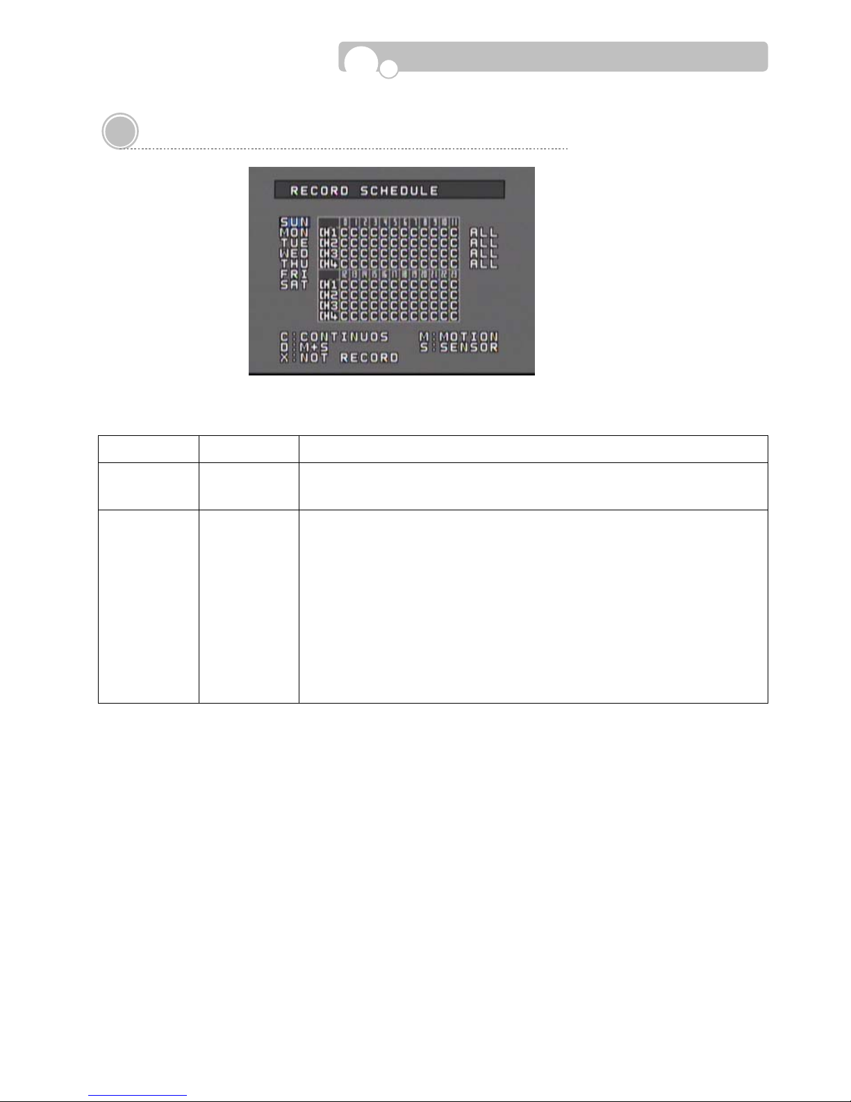
3.4. Record Schedule
The recording time can be set according to Channels, Weekday , and Time.
CATEGORY DEFAULT ADJUSTMENTS
WEEKDAY SUN
Select the WEEKDAY Scheduling.
[Up, Down] : Change WEEKDAY
SCHEDULE
TABLE
D
Set the Recording method.
C : Continuous
M : Motion Detection
D : Dual Mode (Motion + Sensor)
S : Sensor
X : No recording
[NEXT, PREVIOUS] : Move between Weekday and Time Table
[Up, Down, Left, Right] : Move to select Channel & Time
[ENTER] : C → M → D → S → X → C→….
(Select ALL and apply the same recording method for the whole day.)
Configuration

- 22 -
3.5. Sensor Setup
CATEGORY DEFAULT ADJUSTMENT
SENSOR
NO.
1
Set the SENSOR Number .
[Left, Down] : Decrease Number
[Right, Up] : Increase Number
SENSOR
TYPE
NO
Select the SENSOR TYPE
[Up, Down, Left, Right] : Select NO or NC
CAMERA
LINK
Select the CAMERA that is to be connected to the SENSOR
[Left, Down, Right, Up] : Move between channels
[ENTER] : T oggle to Enable/Disable
ALARM
LINK
Select the ALARM OUTPUT that will be connected to the SENSOR
[Left, Down, Right, Up] : Move between channels
[ENTER] : T oggle to Enable/Disable
OPERATION
TIME
0~24
Set the OPERATION TIME for the selected sensor. (Start Hour ~ End Hour)
It will not activate if same time is set.
Range : 0~24(Hour), OFF
[Left, Right] : Move between Start ~ End
[Up, Down] : Increase/Decrease hour .
Number keys can also be used to change the hour .
OPERATION
MODE
SPOT
Set whether to show the camera v iew in full screen on the Spot monitor when
the sensor is triggered.
[NORMAL] : Disable
[SPOT] : Apply
If a sensor is linked to several channels, the channels will be displayed in the
multi-screen mode.
[Up, Down, Left, Right]: Move between NORMAL Ù SPOT
RECORDING
DWELL TIME
30
Set the time duration for which the camera will continue recording when the
sensor is triggered.
Input Range : 0~600(Second)
[Left, Down] : Decrease dwell time
[Right, Up] : Increase dwell time
Number keys can also be used to change the dwell time.
Configuration

- 23 -
CATEGORY
DEFAULT
ADJUSTMENT
OUTPUT
DWELL TIME
30
Set the duration for which the Alarm(Output) will continue after the sensor is
triggered.
Input Range : 0~600(Second)
[Left, Down] : Decrease duration
[Right, Up] : Increase duration
Number keys can also be used to change the dwell time.
BEEP
Set whether to use the DVR Buzzer wh en a sensor is triggered.
[ENTER] : Toggle Enable/Disable
Configuration

- 24 -
3.6. Network Setup : Page 1
CATEGORY DEFAULT ADJUSTMENT
NAME
Set the DVR NAME.
Use the Numeral/Letter/Symbol buttons or the [Up, Down] buttons to input
the Name.
[Left, Right] : Move to previous/ next space
[Up, Down] : Select letter , number, symbol
TYPE FIXED
Select IP T ype.
[Up, Down, Left, Right]: Move between FIXED Ù AUTO ÙPPPOE
PORT
Set the PORT number that will be connected to the Network.
Range : 0~65535
[Left, Down] : Decrease number
[Right, UP] : Increase number
Number keys can also be used to change the Port number .
IP
Set the IP Address of the DVR.
[Left, Right] : Move to next number field
[Up, Down] : Increase/Decrease number
Number keys can also be used to change the IP address
GATEWAY
Set the GATEW AY Address of the DVR.
[Left, Right] : Move to next number field
[Up, Down] : Increase/Decrease number
Number keys can also be used to change the Gateway address
SUBNET
Set the SUBNET MASK Number of the DVR.
[Left, Right] : Move to next number field
[Up, Down] : Increase/Decrease number
Number keys can also be used to change the Subnet number .
DNS
Set the DNS Address.
[Left, Right] : Move to next number field
[Up, Down] : Increase/Decrease number
Number keys can also be used to change the DNS address.
Configuration

- 25 -
CATEGORY DEFAULT ADJUSTMENT
SMTP
Set the SMTP Address.
[Left, Right] : Move to next number field
[Up, Down] : Increase/Decrease number
Number keys can also be used to change the STMP address.
MAC
Display the MAC Address of the DVR.
MAC Address is pre-set during production and cannot be changed.
PPPOE ID
Set the PPPOE ID for internet connection when using ADSL modems.
[Up, Down] : Select letter , number, symbol.
[Left, Right] : Move to next space
Numeral/Letter/Symbol keys can also be used to change the ID
Input Range : Max. 16 characters(Combination of Numeral/Letter/Symbol).
PPPOE
PASSWORD
Set the PPPOE PASSWORD for internet connection when using ADSL modems.
[Up, Down] : Select letter , number, symbol.
[Left, Right] : Move to next space
Numeral/Letter/Symbol keys can also be used to change the Password
Limit: Max. 16 characters(Combination of Numeral/Letter/Symbol).
Configuration

- 26 -
3.6. Network Setup : Page 2
CATEGORY DEFAULT ADJUSTMENT
E-MAIL
AUTHORITY
NO
Set whether E-Mail Login is required for E-MAIL notification when a sensor is
triggered
[Up, Down, Left, Right] : Select YES or NO
AUTH-ID
Set the E-Mail Login ID.
[Up, Down] : Select letter , number, symbol.
[Left, Right] : Move to next space
Numeral/Letter/Symbol keys can also be used to change the ID
Limit : 16 characters(Combination of numbers and letters).
AUTH- PASS
Set the E-Mail Login Password.
[Up, Down] : Select letter , number, symbol.
[Left, Right] : Move to next space
Numeral/Letter/Symbol keys can also be used to change the Password.
Limit : 16 characters(Combination of numbers and letters).
E-MAIL FROM
Enter the E-MAIL address of the SENDER
[Up, Down] : Select letter, number, symbol.
[Left, Right] : Move to next space
Numeral/Letter/Symbol keys can also be used to input the Address.
Limit: 50 characters.
E-MAIL TO
Enter the E-MAIL address of the RECEIVER.
[Up, Down] : Select letter , number, symbol.
[Left, Right] : Move to next space
Numeral/Letter/Symbol keys can also be used to input the Address.
Limit : 50 characters.
EVENT MAIL
Select EVENTS for automatic transmission of e-mail notifications
[Up, Down, Left, Right] : Move between the Events.
[ENTER] : T oggle to Check/Disable
Configuration

- 27 -
3.7. Display Setup
CATEGORY DEFAULT ADJUSTMENT
OSD ALL
OSD(On Screen Display)
Designate which information to be shown on the monitoring screen.
[Left, Up] : Move to upper category
[Right, Down] : Move to lower category
[ENTER] : T oggle to Apply /Disable
BORDER
COLOR
GRAY2
Set the BORDER COLOR of screen
[Left, Up] : Move to upper category .
[Right, Down] : Move to lower category .
[ENTER] : T oggle to Apply /Disable
SEQUENCE
DWELL TIME
5
Set the SEQUENCE DWELL TIME of the monitoring channels
Range : 1~60(Second)
[Left, Down] : Decrease number
[Right, UP] : Increase number
Number keys can also be used to change the dwell time
VGA
DEINTERLACING
BOB
When viewing video in the progressive(VGA) scan mode the interlaced image
is transformed to the progressive image,
and if there is moving images, horizontal Lines(Tearing) will appear on the
screen. Selecting BOB will make the tearing disappear and if there is no
moving images selecting WEAVE will provide a clearer image.
[Up, Down, Left, Right] : Select between BOB Ù WEAVE
[ENTER] : Apply and move to next category.
Configuration

- 28 -
3.8. Backup & Format
CATEGORY ADJUSTMENT
BACKUP
Set the STAR T -END TIME of a recorded video for Backup
[Left, Right] : Move between Year/Month/Day/Time
[Up, Down] : Increase/Decrease number
Number keys can also be used to change date & time
Select the backup memory device(USB) and move to START.
[ENTER] : Activate ST ART.
FORMAT
Format the internal HDD or External Memory(USB)
[Left, Right] : Move between the memory drives.
Select the memory to be formatted and activate START
※ The DVR supports only the FA T32 file system.
※ Recording will stop during formatting.
Configuration

- 29 -
4.1. Monitoring
Monitoring Screen
The video signals received by the DVR can be viewed
on Multi-Screens or the image can be viewed in the
Pause and Zoom mode.
Date, Time, Camera Number, Recording Status, HDD
Capacity Usage are displayed on the screen.
Information displayed on the screen(OSD) can be changed
by pressing the [OSD] button or the DVR front panel
[ESC] button..
When recording is in progess, Letter “R” will appear in the
center of the screen.
FREEZE
FREEZE is a function to view still image during monitoring.
(Recording will continue).
Press the [FREEZE] button for still image viewing.
Press the [FREEZE] button again to resume monitoring.
During Freeze mode, Letter “F” will appear in the center
of the screen.
ZOOM
ZOOM mode allows 200% magnification of the selected
area of the screen.
Press the [ZOOM] button and the magnification area will
appear on the center of the screen.
The magnification area can be moved horizontally and
vertically by pressing the [Up, Down, Left, Right] buttons.
Pressing the [Enter] button each time will magnify/
de-magnify the selected area.
Press the [ESC] button to escape from ZOOM mode.
4.
O
PERATION

- 30 -
SEQUENCE DISPLAY
Single screen sequence display is possible by pressing the [SEQUENCE] button.
The Sequence Dwell Time can be set in the [SETUP] – [DISPLAY] menu.
icon will appear on the screen during the Sequence Display mode.
4.2. PTZ Control
This is a mode to control Camera Direction/Focus/Zoom/Preset/Swing/P attern/Group during the Monitoring
Mode.
Press the [PTZ] button or press the [MENU] button and select PTZ.
The window showing the PTZ control status will appear on the bottom of the screen
CATEGORY OPERATION
CHANNEL
Select the channel you wish to control.
[CH] : Change channels
PAN / TILT
[Left, Up] : Move camera up and down.
[Right, Down] : Move camera left and right.
ZOOM
Use ZOOM buttons to zoom in/out.
FOCUS
Use the FOCUS buttons to focus in/out.
APERTURE
Use the IRIS buttons to adjust the aperture.
T o display the Preset/Swing/Pattern/Group/Setting menu, press [ENTER] after selecting the channel
Select PRESET to set the presets for a PTZ camera.
Select SETTING to set the Swing/Pattern/Group movement of the PTZ Camera.
Operation
※ Please refer to the Operation Manual of the PTZ camera to setup SWING, PATTERN,
GROUP configurations.

- 31 -
4.3. Recording
The initial recording configuration for this DVR is set up as fol lows :
CATEGORY DEFAULT VALUE
RECORDING SPEED
- NTSC
- PAL
15FPS(Frames Per Second)
12FPS(Frames Per Second)
RECORDING QUALITY MIDDLE
RESOLUTION
- NTSC
- PAL
352x240(CIF)
352x288(CIF)
RECORDING SCHEDULE CONTINUOUS
AUDIO RECORDING ALL
FULL DISK OVERWRITE
WATERMARK NO
※ To change the above configurations, enter SETUP and change the settings from the RECORD SET and
RECORD SCHEDULE menus.
※ Recording Indicator : The following indicator will appear on the monitoring screen for each channels.
-
R : Recording schedule has been set up.
- Blinking
R : Actual recording is in progress.
- Blinking
M : Motion detection recording is in progress
- Blinking
S : Sensor activated recording in progress.
PANIC RECORDING
Press the PANIC button during an emergency to activate recordings of all cameras at the highest recording
quality level and the OSD “R” will change to “
!”.
RECORDING SPEED : 30FPS/NTSC, 25FPS/PAL
RECORDING QUALITY : SUPER
※ The resolution will remain in its original recoding setting.
You ma y de-activ ate the P ANIC recording by pressing th e PANIC butt on once again and the DVR will continue
to operate based on the original recording setting s.
Operation
- 32 -
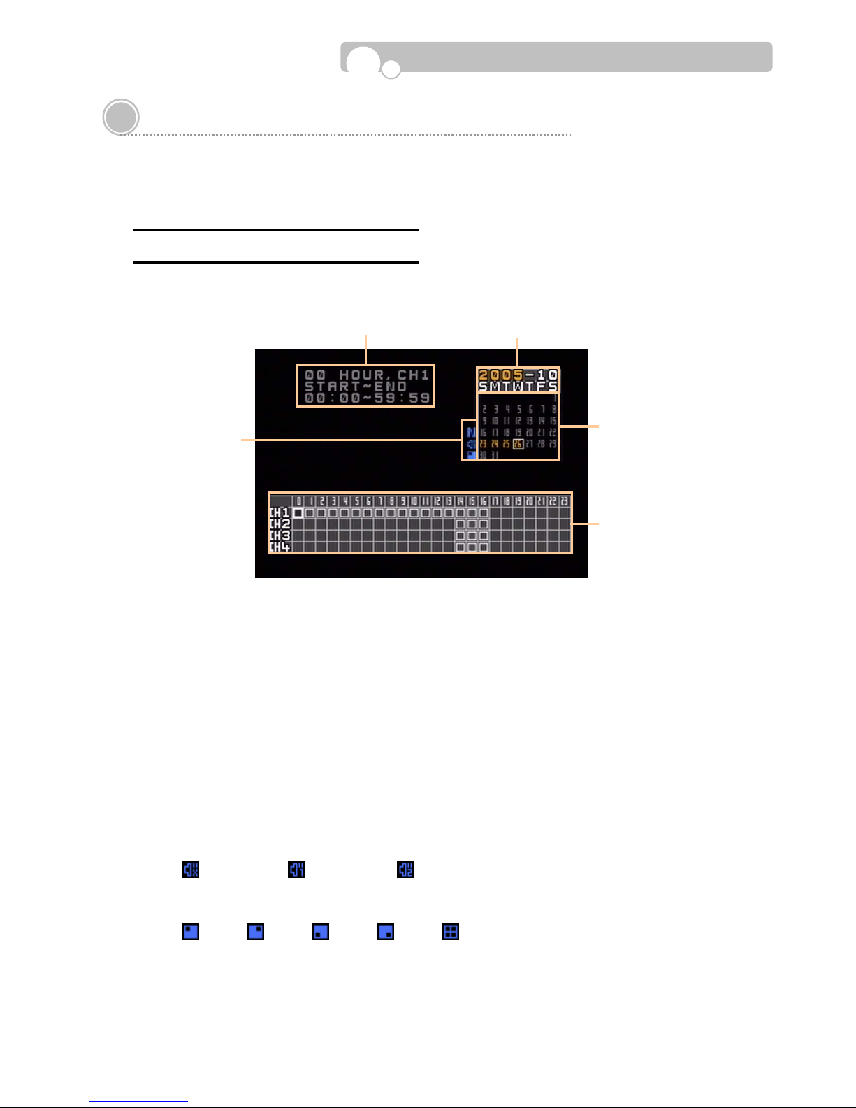
4.4. Search (Playback)
You may search the recorded video data of the DVR by using the Time Search Mode.
Enter the [SEARCH] menu and select “DVR” using the [Up. Down] buttons and press [ENTER].
DVR Se arc h : TIME & DATE SEARCH
The following Time Search Mode will appear on the screen.
① YEAR - MONTH
② DAY
③ Hour/Channel Table
The recording information will be shown on the Hour and Channel(camera) Table for the selected
Day.
④ Recording Information
The recording information of the selected Hour will be shown as “Minute: Second
~ Minute: Second” .
⑤ Playback Information
1) Audio Channel
The audio channel status will be indicated as follows..
(AUDIO OFF) , (AUDIO 1 ON), (AUDIO 2 ON)
2) Multi-Screen Display mode
The multi-screen display mode will be indicated as follows.
: CH1, : CH2, : CH3, : CH4, : 4 Multi-screen mode
② ⑤
③
④ ①
Operation

- 33 -
SEARCH PROCEDURE
By selecting the [SEARCH] menu, information of the first file recorded on the current day will appear on
the screen. And the search procedure will start from the “Day” indication field.
1) Select the Year and Month.
On the calendar , days containing recorded data will be highlighted in y ellow.
2) Select the Day.
Move to the relevant Day and the recording information for the corresponding Day will be
indicated on the Hour/Channel indication table.
Button Function
Left, Right Move between Y ear Ù Month
Up, Down Change the Y ear and Month
ENTER, NEXT Move to the Day indication field
PREV Move to the Hour/Channel indication table
Operation
- 34 -
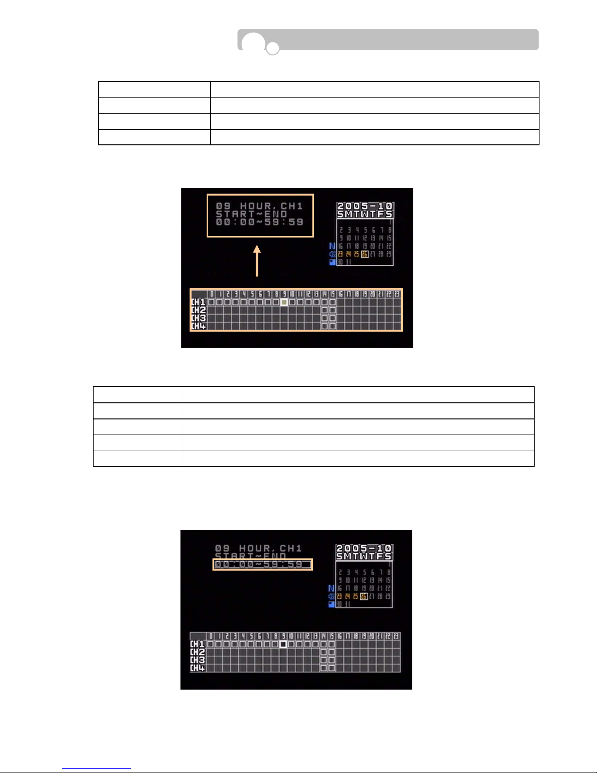
3) Select the relevant Hour/Channel.
The relevant recording file list will appear on the upper left corner of the screen for the selected Hour/Channel.
4) Select the relevant time range(Minute : Second ~ Minute :Second) and press [Enter] button to
play the recording.
Button Function
Up, Down, Left, Right Move to the desired Day
ENTER, NEXT Move to the Hour/Channel indication table
PREV PREV : Move to “Year-Month” indication field
Button Function
Left, Right Move to relevant hour
Up, Down Move to relevant Channel (CH1 ~ CH4, QUAD Button)
ENTER, NEXT Move to R ecording File List
PREV PREV : Move to Day indication field
Operation

- 35 -
FULL SCREEN DISPLAY
The playback screen can be changed to the full screen
mode by pressing the [FULL SCR] button.
Playback Information will appear on the lower part of
the screen.
Press the [OSD] button to make the Playback
information disappear or appear.
Press the [FULL SCR] button again to return to the Time
& Date Search mode.
< Playback Information >
Button Function
Up, Down Move from file to file(Time range)
ENTER Start playback
PREV, NEXT
PREV : Move to Hour/Channel indication table
NEXT : Move to “Year-Month” indicator
Time Indicator
Audio/Display Status
Date Indicator
Playback Information
Operation

- 36 -
USB Search
Data saved on a USB Memory Stick may be played back by following the USB SEARCH procedure.
Sel e c t th e [ S EA R C H ] m en u a n d m o v e t o “ US B ” b y using the [Up, Down] buttons. Then press the [ENTER]
button to enter the USB Time Search Mode.
SEARCH PROCEDURE
The following display will appear on the screen.
Video data stored in the USB will appear according
to the recording dates.
Select the date you wish to search by using the
[Up, Down] buttons and press [ENTER].
If data exists for the selected date, the following
time list will appear on the screen.
Select the relevant time and press [ENTER] to
start playback.
The playback will proceed in the Full Screen Mode.
Operation

- 37 -
4.4. Log Search
All events that occur on the DVR are recorded in the Log List.
Select the [LOG] Menu and the following LOG Time Search mode will appear.
① SORT
Selection of LOG types.
② LOG LIST
List of events of the selected LOG type.
Type Explanations
POWER Power On/Off
SENSOR Sensor Input
RECORD Record Start/Stop
CAMERA Camera Input Signal data
NETWORK Network connections
BACKUP Start Backup
SETUP Setup Enter/Exit/Save
CLOCK Date/Time adjustments
① ②
Operation

- 38 -
SEARCH PROCEDURE
1) Select the relevant “Year, Month”.
On the calendar , days containing LOG records will be highlighted in yellow .
2) Select the desired Day.
Move to the desired Day , then the corresponding log records of the selected Day will appear in
the LOG List at the bottom of the screen.
Button Function
Left, Right T oggle between Y ear Ù Month
Up, Down Select the relevant Y ear and Month
ENTER Move to the Day indication field
PREV, NEXT
PREV : Move to LOG List(If log records exist for the selected date.)
NEXT : Move to Day indication field
Button Function
Up, Down, Left, Right Move to relevant Day
ENTER Move to LOG List
PREV, NEXT
PREV : Move to “Year-Month” indication field
NEXT : Move to SORT
Figure 33
Operation

- 39 -
3) SORT
Select the desired type of log information of the selected Day.
4) Event Playback
Video recordings activated by Alarm Inputs are listed in the LOG List(SENSOR) and the recordings can be
played back by selecting “SENSOR ON” from the list and pressing the [ENTER] button. (If recorded data
exists)
Button Function
Up, Down
Select the SORT category .
(Select among ALL, POWER, SENSOR, RECORD, CAMERA, LAN, BACKUP, SETUP,
TIME.)
ENTER
Display log list of the selected event selected. (If log records exist for the selected
event.)
PREV, NEXT
PREV : Move to Day indication field
NEXT : Move to LOG List(If log records exist for the selected date.)
Operation

- 40 -
4.5. Video Clip Copy
Video Clip copies of recorded video datas can be made to a USB Memory Stick by taking the following
steps.
COPY PROCEDURE
1) Enter SEARCH(DVR).
2) Follow the procedure explained in DVR SEARCH to find the relevant video data and activate playback.
3) Find the Starting location of the video clip you wish to make a copy and press the [CAPTURE] button to
designate the Starting location. The video will be put on pause and you will be required to select the
external memory device on which the copy will be made.
※ The free memory space of the external memory device and the file size of the video clip will be
indicated on the screen. The free memory space of the external memory device must b e larger
than the video clip file size in order to make a copy.
4) Use the Play , F ast F orw ard/Rev erse, Slow Motion, Skip buttons to find the end of the video clip you wish
to copy and press the [CAPTURE] button to designate the End location.
5) Copying will proceed and the copy progress rate will be indicated on the screen.
※ The [CAPTURE] button can only be used during playback.
※ Y ou may return to the monitoring mode during the copying process by pressing the [ESC]
button.
Operation

- 41 -
Appendix
Technical Specification
Category Specification
Operating System Embedded Proprietary OS
Compression Algorithm MPEG4(VIDEO) , ADPCM(SOUND)
Byte Size per Frame
1.5~6KByte/Frame @ 352x240(352x288)
6~24KByte/Frame @ 720x480(720x576)
Multi-Screen Display 1/4/Sequence
Video Input 4 BNC
Monitor Output 1 Composite, 1 VGA, 1 S-Video
Display Speed 120fps
Recording Resolution
NTSC : 352x240, 720x480
PAL : 352x288, 720x576
Recording Speed(CIF)
Max 120fps(NTSC), Max 100fps(PAL)
Recording Mode Continuous, Schedule, Event(Sensor, Motion Detection)
Audio 2 Line-In / 1 Line-Out
Search Method Time & Date, Event(Sensor)
Sensor Alarm 4 Alarm Input(NO/NC) / 2 Alarm Output
PTZ Interface RS-485
Storage Max. 2 HDD IDE
External Backup USB Memory , Network
System Control Front Panel, IR Remote Controller, Network
Network DHCP, DDNS, PPPoE, TCP/IP Ethernet
Special Features
SMART Warning, Virus Free, Masking, T riplex Operation(Simultaneous Playback,
Recording, Networking), Covert Recording.
Remote Management Remote Configuration, Software Upgrade, PTZ Control
Verification Digital Watermark
Dimension(W x H x D) 278mm x 88mm x 260mm
Weight 3.3kg
Power Supply S witchable AC100~110/220~230V, 50~60Hz
 Loading...