

Page 1
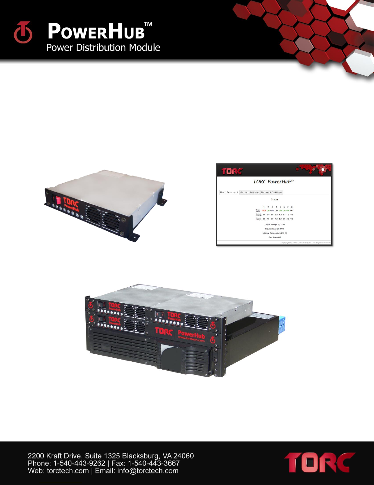
Single Unit
Web Configuration Utility
Rack Mounted Units
The PowerHub power distribution modules provide eight outputs at 5V, 12V or
24V, and are controlled over Ethernet for easy integration with unmanned and
autonomous vehicle computer systems. The modules are capable of distributing
up to 500W and are available in standalone or rackmount configurations.
User Manual
Intelligent Power Distribution
Page 2

PowerHubTM User Manual, Version 1.2
TABLE OF CONTENTS
1 ASSIGNMENT OF LIABILITY ....................................................................................................... 3
2 GENERAL SAFETY INFORMATION ............................................................................................ 4
3 PACKAGE CONTENTS .................................................................................................................... 5
4 POWERHUB OVERVIEW .............................................................................................................. 6
5 POWERHUB SPECIFICATIONS ................................................................................................... 7
5.1 Electrical specifications ............................................................................................................................. 7
5.2 Interface / Contact Ratings ...................................................................................................................... 11
5.3 Visual Indicators ...................................................................................................................................... 11
5.4 Environmental ......................................................................................................................................... 11
6 WEB-BASED CONFIGURATION ................................................................................................ 12
6.1 The Status Tab ......................................................................................................................................... 12
6.2 The Output Settings Tab .......................................................................................................................... 14
6.3 The Network Settings Tab ....................................................................................................................... 15
7 ADVANCED COMMUNICATION PROTOCOL ......................................................................... 16
7.1 PuTTY configuration ................................................................................................................................ 17
8 POWERHUB DETAIL ................................................................................................................... 19
8.1 Front View............................................................................................................................................... 19
8.2 Rear View ................................................................................................................................................ 20
8.3 Connector Pinouts ................................................................................................................................... 21
8.4 Remote Enable Connection ..................................................................................................................... 23
9 PHYSICAL DIMINSIONS AND MOUNTING ............................................................................ 23
1
Page 3

PowerHubTM User Manual, Version 1.2
9.1 Rack mount Faceplate Dimensions .......................................................................................................... 24
9.2 Standalone Mounting Configuration ....................................................................................................... 26
10 LIMITED WARRANTY ............................................................................................................. 27
2
Page 4

PowerHubTM User Manual, Version 1.2
1 ASSIGNMENT OF LIABILITY
WARNING: DO NOT OPERATE UNTIL USER MANUAL IS REVIEWED AND UNDERSTOOD. PRODUCT USE IS
SUBJECT TO STRICT TERMS AND CONDITIONS. SEE CUSTOMER AGREEMENT FOR ADDITIONAL USE
RESTRICTIONS. OPERATING PRODUCT IN VIOLATION OF USER RESTRICTIONS COULD RESULT IN
PRODUCT MALFUNCTION, PROPERTY DAMAGE, AND PERSONAL INJURY INCLUDING DEATH.
NOTICE: USER ASSUMES ALL RISKS ASSOCIATED WITH POSSESSION OR USE OF PRODUCT AND RELATED
SYSTEMS. USER AGREES TO INDEMNIFY, DEFEND AND HOLD HARMLESS TORC FROM ANY DAMAGES
ARISING OUT OF POSSESSION OR USE OF PRODUCT AND RELATED SYSTEMS. TORC IS NOT LIABLE FOR
ANY DAMAGES OF ANY KIND.
3
Page 5

GENERAL SAFETY INFORMATION
WARNING: Indicates a hazardous condition that could result in serious injury or loss of
life if not performed properly.
CAUTION: Indicates a hazardous condition or procedure that could result in damage to
this product, or loss related to equipment malfunction.
NOTE: A note indicates information that may not be applicable regarding system safety
but needs to be known for best system performance.
The following symbols are used throughout the user manual to indicate a particularly hazardous
condition.
Read this manual before using the PowerHub.
Make sure to read this manual in its entirety before using the PowerHub. Failure to follow the
instructions and warnings contained in this manual could result in damage to the unit or the
external devices it is connected to.
Do Not Operate With Suspected Failures.
If you suspect there is damage to the product, contact TORC Technologies to have it inspected
before further use.
Do Not Attempt to Modify or Disassemble.
To avoid shock hazard and/or damage to the product, do not attempt to open the case, make
modifications, or repair the device. Opening, modifying or repairing this device will void any
applicable warranty and could prevent the device from operating properly.
Do Not Operate in Wet/Damp Conditions.
To avoid shock hazard and/or product malfunction, do not operate in a wet or damp
environment.
PowerHubTM User Manual, Version 1.2
4
Page 6
2 PACKAGE CONTENTS
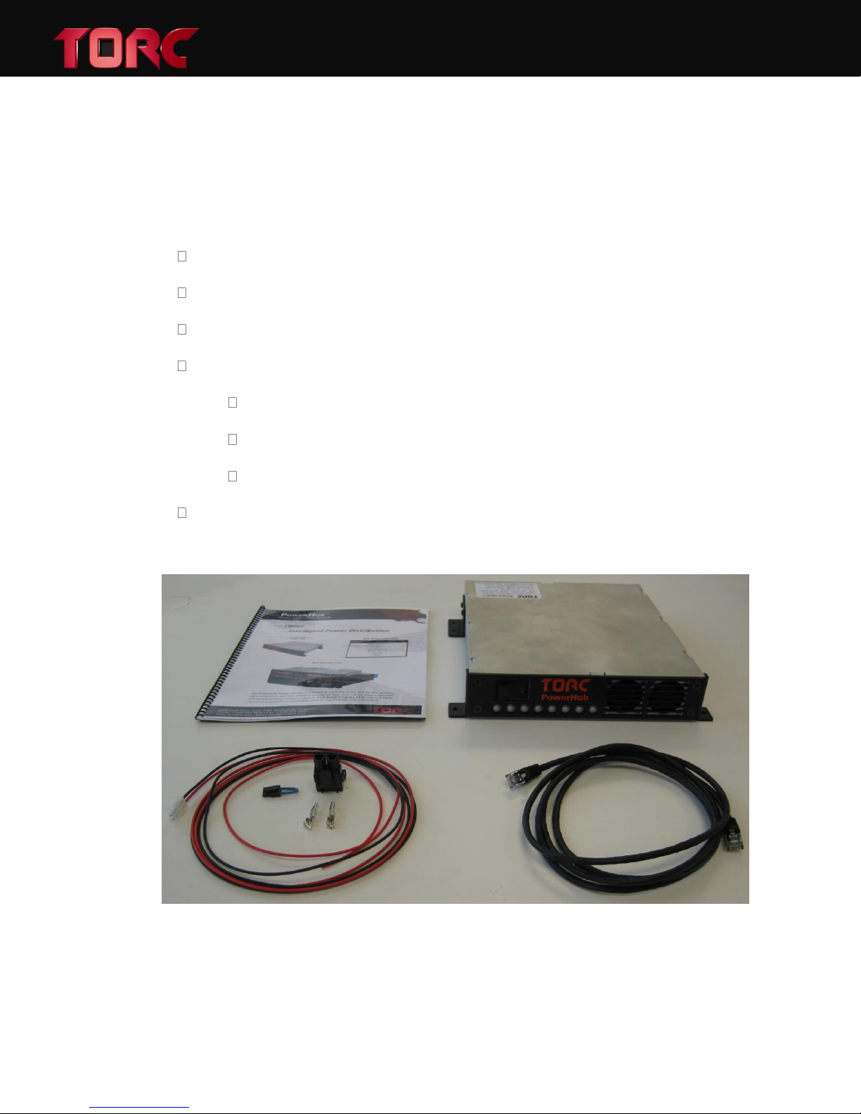
After unpacking the contents of the PowerHub system, please verify the contents of the package
includes the following items:
PowerHub™ Module with Faceplate
Network Cable
User Manual
Starter Kit
Remote Enable Jumper
Input Connector and Pins
PowerHubTM User Manual, Version 1.2
Output Cables (x4) (single output cable displayed)
Mounting Bracket (Standalone Only)
Figure 1: PowerHub Package Contents (standalone faceplate with optional mounting bracket)
5
Page 7

3 POWERHUB OVERVIEW
The TORC PowerHub provides computer controlled power distribution designed for applications
in unmanned systems. The PowerHub is available with a 12V, 24V, or 48V nominal input, and a
5V, 12V, or 24V nominal output. Convenient control over Ethernet allows each of the 8 outputs
to be switched and monitored remotely. An intuitive web interface allows the user to directly
configure and use the PowerHub during testing and development. In addition, a simple TCP
protocol allows for advanced computer control. The PowerHub provides unmanned systems
developers with a compact and highly functional power conditioning and distribution solution,
allowing them to focus on more complex design and control tasks.
PowerHubTM User Manual, Version 1.2
6
Page 8

4 POWERHUB SPECIFICATIONS
Parameter
Min
Typ
Max
Unit
Notes
Operating input voltage
36
48
60
Vdc Adjusted output voltage
19.2
24
26.4
Vdc
nominal input; full load; 25°C
Output Power
500 W nominal input; 24VDC output
Output ripple
75 mV
p-p; nominal input; full load
Load regulation
0.02
0.2
%
nominal input; no load to full
Efficiency
85 %
nominal input; full load; 25°C
Disabled power consumption
0.05
W remote disable
Enabled power consumption
1.3 W
outputs off, no load
13.3
W outputs on, no load
Parameter
Min
Typ
Max
Unit
Notes
Operating input voltage
36
48
60
Vdc Adjusted output voltage
10.5
12
16.5
Vdc
nominal input; full load; 25°C
Output Power
400 W nominal input; 12VDC output
Output ripple
85 mV
p-p; nominal input; full load
Load regulation
0.02
0.2
%
nominal input; no load to full
Efficiency
87 %
nominal input; full load; 25°C
Disabled power consumption
0.05
W remote disable
Enabled power consumption
1.3 W
outputs off, no load
15.3
W outputs on, no load
Parameter
Min
Typ
Max
Unit
Notes
Operating input voltage
36
48
60
Vdc Adjusted output voltage
4.5 5 5.5
Vdc
nominal input; full load; 25°C
Output Power
400 W nominal input; 12VDC output
Output ripple
80 mV
p-p; nominal input; full load
Load regulation
0.02
0.2
%
nominal input; no load to full
Efficiency
82 %
nominal input; full load; 25°C
Disabled power consumption
0.05
W remote disable
Enabled power consumption
1.3 W
outputs off, no load
12.6
W outputs on, no load
4.1 Electrical specifications
PH482401
PH481201
PowerHubTM User Manual, Version 1.2
PH480501
7
Page 9

PH242401
Parameter
Min
Typ
Max
Unit
Notes
Operating input voltage
18
24
36
Vdc Adjusted output voltage
19.2
24
26.4
Vdc
nominal input; full load; 25°C
Output Power
400 W nominal input; 24VDC output
Output ripple
80 mV
p-p; nominal input; full load
Load regulation
0.02
0.2
%
nominal input; no load to full
Efficiency
86 %
nominal input; full load; 25°C
Disabled power consumption
0.05
W remote disable
Enabled power consumption
1.3 W
outputs off, no load
16.3
W outputs on, no load
Parameter
Min
Typ
Max
Unit
Notes
Operating input voltage
18
24
36
Vdc Adjusted output voltage
10.5
12
16.5
Vdc
nominal input; full load; 25°C
Output Power
320 W nominal input; 12VDC output
Output ripple
160 mV
p-p; nominal input; full load
Load regulation
0.02
0.2
%
nominal input; no load to full
Efficiency
85 %
nominal input; full load; 25°C
Disabled power consumption
0.05
W remote disable
Enabled power consumption
1.3 W
outputs off, no load
11.6
W outputs on, no load
Parameter
Min
Typ
Max
Unit
Notes
Operating input voltage
18
24
36
Vdc Adjusted output voltage
4.5 5 5.5
Vdc
nominal input; full load; 25°C
Output Power
400 W nominal input; 5VDC output
Output ripple
152 mV
p-p; nominal input; full load
Load regulation
0.02
0.2
%
nominal input; no load to full
Efficiency
80 %
nominal input; full load; 25°C
Disabled power consumption
0.05
W remote disable
Enabled power consumption
1.3 W
outputs off, no load
12.5
W outputs on, no load
PH241201
PowerHubTM User Manual, Version 1.2
PH240501
8
Page 10

PH122401
Parameter
Min
Typ
Max
Unit
Notes
Operating input voltage
10
24
36
Vdc Adjusted output voltage
19.2
24
26.4
Vdc
nominal input; full load; 25°C
Output Power
200 W nominal input; 24VDC output
Output ripple
315 mV
p-p; nominal input; full load
Load regulation
0.02
0.2
%
nominal input; no load to full
Efficiency
82 %
nominal input; full load; 25°C
Disabled power consumption
0.05
W remote disable
Enabled power consumption
1.3 W
outputs off, no load
17.6
W outputs on, no load
Parameter
Min
Typ
Max
Unit
Notes
Operating input voltage
10
24
36
Vdc Adjusted output voltage
10.5
12
16.5
Vdc
nominal input; full load; 25°C
Output Power
160 W nominal input; 12VDC output
Output ripple
220 mV
p-p; nominal input; full load
Load regulation
0.02
0.2
%
nominal input; no load to full
Efficiency
81 %
nominal input; full load; 25°C
Disabled power consumption
0.05
W remote disable
Enabled power consumption
1.3 W
outputs off, no load
18 W
outputs on, no load
Parameter
Min
Typ
Max
Unit
Notes
Operating input voltage
10
24
36
Vdc Adjusted output voltage
4.5 5 5.5
Vdc
nominal input; full load; 25°C
Output Power
175 W nominal input; 5VDC output
Output ripple
280 mV
p-p; nominal input; full load
Load regulation
0.02
0.2
%
nominal input; no load to full
Efficiency
74 %
nominal input; full load; 25°C
Disabled power consumption
0.05
W remote disable
Enabled power consumption
1.3 W
outputs off, no load
19.7
W outputs on, no load
PH121201
PowerHubTM User Manual, Version 1.2
PH120501
9
Page 11
CONTROL AND SENSING
Parameter
Min
Typ
Max
Unit
Notes
Current limit accuracy
0.5 A
25 deg C
Voltage set point accuracy
2
5
%
of nominal output
Temperature accuracy
1
deg C
Output fault shutoff time
2
ms
Output shorted
Aux supply output current
500
mA
Remote enable logic high
Remote enable logic low
2 60
0.8 V V
Internal 100k pull-down
Internal 100k pull-down
OUTPUT DERATING
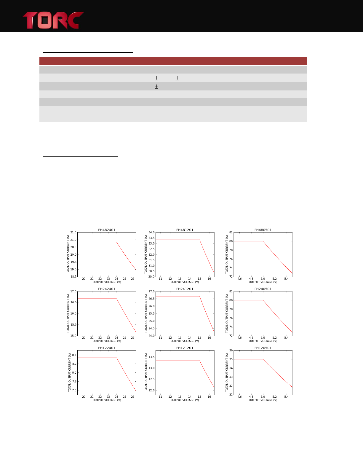
The PowerHub is both current limited and power limited. When operating below the nominal
output voltage, the current is constant and the maximum output power is reduced. When
operating above the nominal output voltage, the power is constant and the maximum output
current is reduced. Exceeding the PowerHub output ratings will cause it to not function
properly until corrected. Refer to Figure 2 for operation outside the nominal output voltage.
PowerHubTM User Manual, Version 1.2
Figure 2: PowerHub Output Derating Curves
10
Page 12

4.2 Interface / Contact Ratings
INPUT CONNECTION
Connector Part Number: Molex 42820-2212
Mating Part Number: Molex 42816-0212
Max Current: 48.0 Amps
OUTPUT CONNECTIONS
Connector Part Number: Molex 39-30-1022
Mating Part Number: Molex 39-01-3028
Max Current Per Output: 9.0 Amps
REMOTE ENABLE CONNECTION
PowerHubTM User Manual, Version 1.2
Connector Part Number: Molex 43650-0303
Mating Part Number: Molex 43645-0300
Max Current: 5.0 Amps
ETHERNET CONNECTION
Standard RJ-45 jack, supporting CAT5, CAT5e, and CAT6 network cables
SERIAL DATA CONNECTION
Standard female DE-9 jack, RS-232 serial communication
4.3 Visual Indicators
Output Status Indication: Bicolor LEDs,
GREEN – output on
RED – overcurrent fault
4.4 Environmental
Operational Temperature: -20°C to 60°C
Operational Humidity: 5% to 90%, non-condensing
Operational Shock Rating: 98 m/s2
11
Page 13
5 WEB-BASED CONFIGURATION
All settings on the PowerHub can be controlled through the web-based configuration utility. To
access the utility, launch a web browser on a computer that is connected to the PowerHub and
enter the PowerHub IP address into the address field. The factory default IP address is
192.168.0.150. If the IP address is forgotten, refer to section 8.2 for instructions on how to
reset the factory defaults.
5.1 The Status Tab
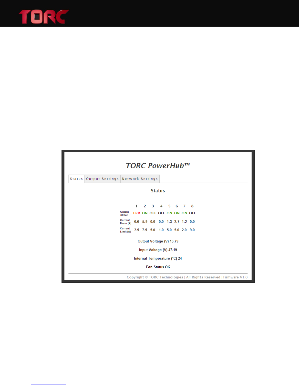
When the configuration page is loaded, the status tab will be displayed as shown below in Figure
3. The status tab displays the current state of each output, the measured input and output
voltages, the internal temperature of the unit, and the fan status. This page is configured to
automatically refresh once every two seconds.
PowerHubTM User Manual, Version 1.2
Figure 3: The status tab of the web based configuration utility.
The output status reflects the current state of each output. The possible states are ON, OFF,
and ERR. When the output is set to the ON state, the positive output terminal is connected to
the output voltage via a solid state relay. In the OFF and ERR states, the positive output
terminal is disconnected from the output voltage and left floating.
12
Page 14

PowerHubTM User Manual, Version 1.2
The current draw and fault current limit for each output is displayed with 100mA resolution.
The fault current limit can be used as a software configurable fuse to ensure that if a particular
output draws higher current than expected, the output is disabled. This prevents one
malfunctioning device from overloading the PowerHub and causing all outputs to be current
limited.
The PowerHub output and input voltages are measured internally and displayed with 10mV
resolution. These voltages are displayed as a reference, confirming the current state of the
module.
The internal temperature of the PowerHub corresponds to the exhaust air temperature and is
provided with 1oC resolution. If the internal temperature of the PowerHub is too high, the
module will shutdown. To resume operation the input power must be cycled using the Master
power switch on the front panel or by the remote enable connection.
Finally, the fan status is displayed as OK if the fans are operating as expected and ERR if one or
both of the cooling fans have stalled. The fan status is only a warning to the user and the
outputs will remain active until the module overheats. If a fan error is detected, the maximum
operational temperature of the PowerHub will be reduced until the error is cleared.
13
Page 15
5.2 The Output Settings Tab
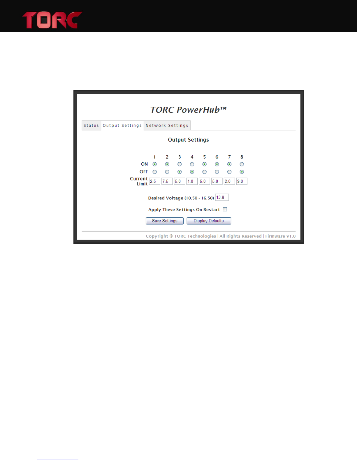
The output settings tab provides the interface to control the function of the PowerHub. The
user can turn outputs ON or OFF, set the current limit, and adjust the desired output voltage.
Figure 4 displays the output settings tab.
PowerHubTM User Manual, Version 1.2
Figure 4: The Output Settings tab of the PowerHub Configuration menu.
After the output settings page is loaded, the ON and OFF radio buttons reflect the current state
of each output. Clicking on the radio buttons for each output will command an on or off state.
If an output fault has occurred, the output state will be displayed as OFF and the error can be
reset by selecting the ON radio button for that channel. Settings will be applied only when the
“Save Settings” button is selected.
Current limits can be adjusted by typing the desired value in the text box. The current limit may
be entered with a 100mA resolution from 0.0 to 9.0A per channel.
Each of the 5V, 12V, and 24V PowerHub units allow the output voltage to be adjusted around
the nominal output voltage of the module. The range of acceptable voltages is displayed in
parenthesis next to the text box where it is entered.
The PowerHub settings can be saved in two ways: default settings or current operation settings.
If saved as default settings, the saved settings will be the power-up configuration of the
PowerHub. Current operation settings, on the other hand, will be lost when the PowerHub is
turned off. To save the output settings as default, select the “Apply These Settings on Restart”
checkbox before saving the changes.
14
Page 16
Pressing the “Save Settings” button will apply the output settings selection. If the user navigates
to another tab before saving, the changes will not applied.
When the “Display Defaults” button is pressed, the current power-up configuration is displayed.
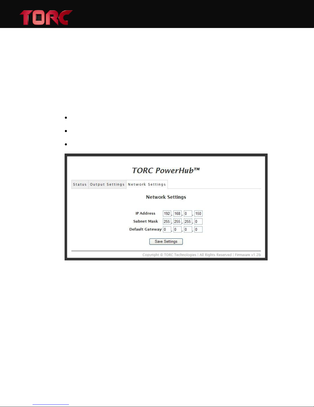
5.3 The Network Settings Tab
The PowerHub can be configured to be accessed as a part of any network by changing the
configurations on the Network Settings tab of the PowerHub configuration menu. The factory
defaults are:
IP Address: 192.168.0.150
Subnet Mask: 255.255.255.0
Gateway: disabled (0.0.0.0)
PowerHubTM User Manual, Version 1.2
Figure 5: The Network Settings configuration tab.
15
Page 17

PowerHubTM User Manual, Version 1.2
6 ADVANCED COMMUNICATION PROTOCOL
In addition to the web interface, the PowerHub also accepts ASCII commands over TCP
(firmware v1.1 and above). The commands are made up of a command word and one or more
arguments separated by spaces. A carriage return (0x0D) followed by a new line (0x0A) denotes
the end of each complete command and terminates each response. Only NVT ASCII characters
are valid, and any telnet option requests will trigger a WONT or DONT response (See RFC 854 for
details). This permits the use of either a standard telnet client or a raw TCP connection to port
23.
The serial port may also be used for sending and receiving advanced communications protocol
messages (firmware v1.2 and above). It is configured for 115200 baud, 8 data bits, no parity, 1
stop bit, and no flow control.
The following commands are available:
ON - Switches an output to the ON state.
Usage: “ON <output numbers, separated by spaces>\r\n”
Example: “ON ALL\r\n” will turn all outputs on
Example: “ON 1 8 4\r\n” will turn outputs 1, 8, and 4 on.
OFF - Switches an output to the OFF state
Usage: “OFF <output numbers, separated by spaces>\r\n”
Example: “OFF ALL” will turn all outputs off
Example: “OFF 1 5 3\r\n” will turn outputs 1, 5, and 3 off.
STATUS - Displays system status
Usage: “STATUS <option>\r\n”
Options:
OUT – Current output state
Example: “STATUS OUT\r\n”
could return “OUT ON OFF OFF ERR ON ON OFF OFF\r\n”
IOUT – Current output amperes
Example: “STATUS IOUT\r\n”
could return “IOUT 1.2 0.0 0.0 0.0 8.5 0.1 0.0 0.0\r\n”
VOUT – Current output voltage
Example: “STATUS VOUT\r\n” could return “VOUT 13.8\r\n”
VIN – Current input voltage.
Example: “STATUS VIN\r\n” could return “VIN 55.0\r\n”
FAN – Current fan state
Example: “STATUS FAN\r\n” could return “FAN OK\r\n” or “FAN ERR\r\n”
16
Page 18

TEMP – Current temperature in degrees Celsius
Example: “STATUS TEMP\r\n” could return “TEMP 25\r\n”
IP – Current IP address
Example: “STATUS IP\r\n” could return “IP 192.168.0.150\r\n”
PowerHub configuration options such as current limits, desired voltage, and network settings
are currently only accessible using the web-based configuration utility.
The freely available telnet/ssh client, “PuTTY” can be used to test the PowerHub advanced
communication protocol. The necessary setup required to use the PuTTY client is outlined in the
following section.
6.1 PuTTY configuration
To configure the PuTTY telnet client for testing the PowerHub advanced communication
protocol, follow the steps outlined below.
PowerHubTM User Manual, Version 1.2
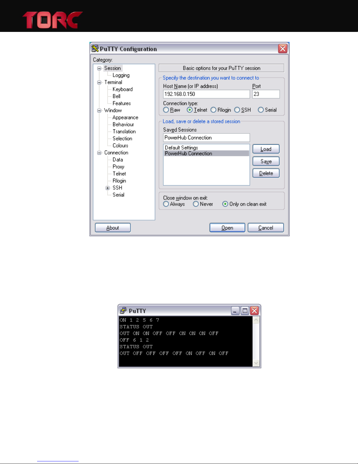
In the “Session” menu, enter the IP address of the PowerHub and select the “Telnet” connection
type (will auto-fill Port 23), shown in Figure 6. If desired, these settings can be saved for future
use by clicking the “Save” button. Once configured, click the “Open” button to create a TCP
connection to the PowerHub.
17
Page 19
PowerHubTM User Manual, Version 1.2
Figure 6: The session tab of the PuTTY configuration menu.
Commands can now be entered into the PuTTY console, validating the PowerHub control over
the TCP communications protocol. A screenshot from an example PuTTY session is included as
Figure 7.
Figure 7: An example using PuTTY to control the PowerHub.
18
Page 20
7 POWERHUB DETAIL
Item
Description
1
Output Indicator LEDs (x8)
2
Input Fans (x2)
3
10-32 Threaded Mounting locations (x4)
4
Master ON/OFF Switch, Circuit Breaker
7.1 Front View
PowerHubTM User Manual, Version 1.2
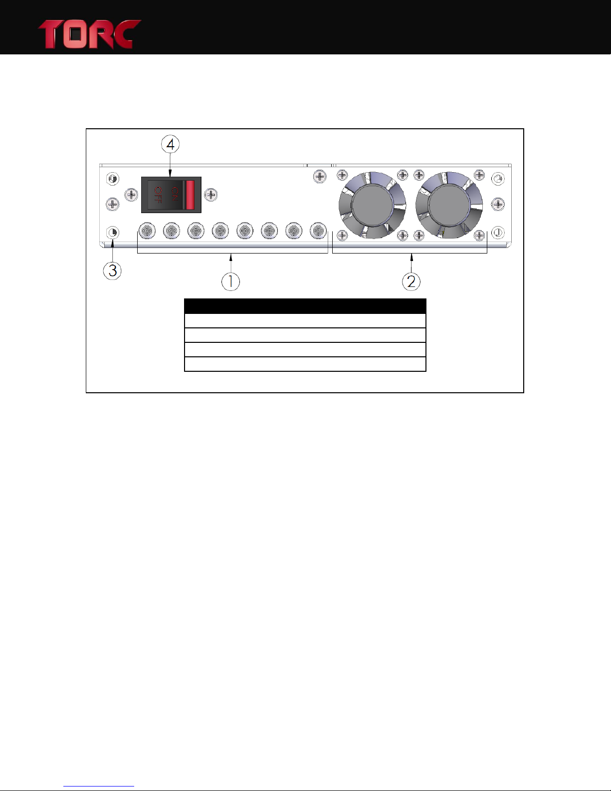
Figure 8: Front View of the PowerHub
On the front face of the PowerHub, there are indicator LEDs (1) for each of the eight outputs.
These LEDs will illuminate GREEN when the corresponding output is enabled and RED if an
overcurrent fault is detected on the output. If the LED is off, the output is OFF. The left most
LED corresponds to output one and the right most LED corresponds to output eight.
The two fans (2) provide forced air cooling of the internal electronics and are turned on
automatically anytime an output is active. Internal fan speed monitoring ensures both fans are
functioning properly. The direction of air flow through the PowerHub is from front to rear.
Four mounting holes (3) on the face of the PowerHub are the primary method of attaching the
device mounting brackets. These holes are threaded for a 10-32 machine screw.
The rocker switch (4) on the front of the PowerHub serves as a dual purpose as the Master
ON/OFF switch and a resettable circuit breaker. This breaker interrupts all input current to the
PowerHub, protecting against a short circuit condition. With the Master Switch in the ON
position, the PowerHub is powered and outputs are under software control via the Ethernet
interface. If the Master Switch is in the OFF position, the PowerHub is disabled and in a zero
power mode.
19
Page 21
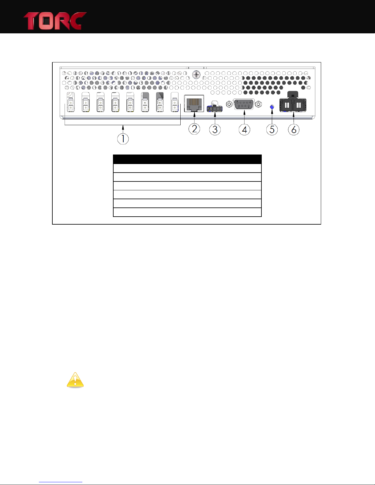
7.2 Rear View
Item
Description
1
Output Connectors (x8)
2
RJ-45 Ethernet Jack
3
Remote Enable Connection
4
Serial Communications Jack
5
Reset to Factory Defaults Button
6
Input Power Connection
CAUTION: Pin 1 on the Remote Enable connector is tied to the input voltage. Ensure
any external circuitry connected to this pin is rated for the input voltage of the unit.
PowerHubTM User Manual, Version 1.2
Figure 9: Rear View of PowerHub
All connections to the PowerHub are located on the rear of the unit. The output connectors (1)
are numbered right to left, one through eight. The output connectors are Molex part number
39-30-1022 and the mating plug is Molex part number 39-01-3028. The output ground, input
ground, and chassis are all connected internally.
The Ethernet jack (2) is an RJ-45 connector located next to the output connectors. The network
interface is a 10/100 Mbps auto-sensing connection.
The remote enable connection (3) allows the PowerHub to be enabled and disabled via external
circuitry (e.g. a vehicle key switch). When disabled, the PowerHub will operate in a very low
power state. If the remote enable capability is not required, a jumper can be used to connect
pins one and three, configuring the PowerHub to always be enabled when the Master Switch is
in the ON position. Refer to Section 7.4 for additional information on the remote enable
feature.
The serial communications jack (4) is a female 9 pin D-subminiature connector. This port is used
for firmware updates as well as the advanced communication protocol messages.
20
Page 22
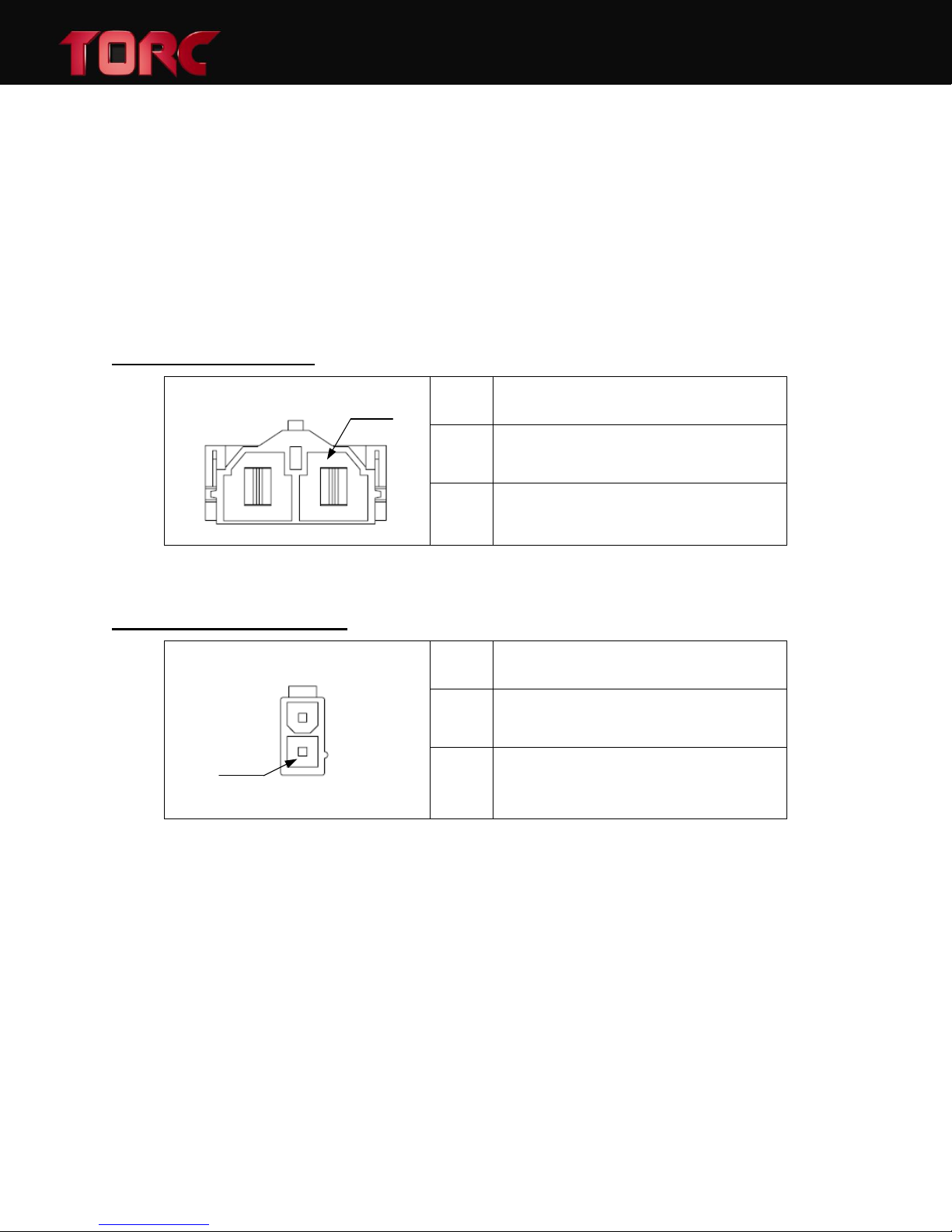
A reset to factory defaults button (5) can be pressed using a paperclip or other small object.
PIN 1
PIN #
DESCRIPTION
1
V
IN+
Positive input terminal
2
GND Negative input terminal
PIN 1
PIN #
DESCRIPTION
1
V
OUT+
Positive output terminal
2
GND Negative output terminal
Holding this button until a beep is heard (approximately 5 seconds) will reset all configuration
settings to the factory defaults. Once the button is released, the PowerHub will reset to apply
the settings.
The input power connector (6) is a Molex 42820-2212 connector. The mating plug is Molex part
number 42816-0212. Pin 1 is positive input and Pin 2 is ground.
7.3 Connector Pinouts
INPUT CONNECTION
PowerHubTM User Manual, Version 1.2
OUTPUT CONNECTIONS
21
Page 23
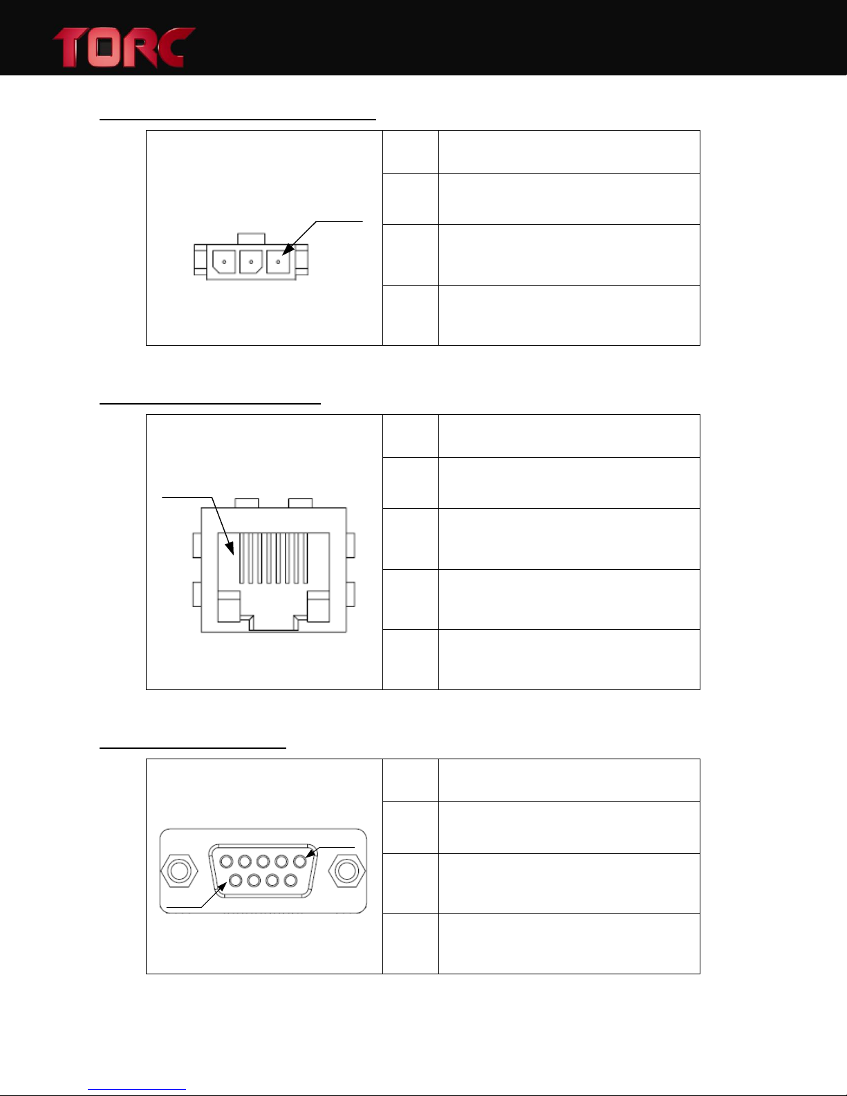
REMOTE ENABLE CONNECTION
PIN 1
PIN #
DESCRIPTION
1
V
REF
Positive output terminal = V
IN+
2
GND Negative output terminal
3
SIG Remote Enable Input (5-60V)
PIN 1
PIN #
DESCRIPTION
1
TXD + Ethernet Transmit Data +
2
TXD - Ethernet Transmit Data -
3
RXD + Ethernet Receive Data +
6
RXD - Ethernet Receive Data -
PIN 1
PIN 9
PIN #
DESCRIPTION
2
TXD RS-232 Transmit Data (To PC)
3
RXD RS-232 Receive Data (From PC)
5
GND RS-232 Signal ground
ETHERNET CONNECTION
PowerHubTM User Manual, Version 1.2
RS-232 CONNECTION
22
Page 24
7.4 Remote Enable Connection
CAUTION: Pin 1 on the Remote Enable connector is fused internally. Always keep any
load on this connector safely below 500 mA.
CAUTION: Pin 1 on the Remote Enable connector is tied to the input voltage. Ensure
any external circuitry connected to this pin is rated for the input voltage of the unit.
3
2
+12V
ACC
1
3
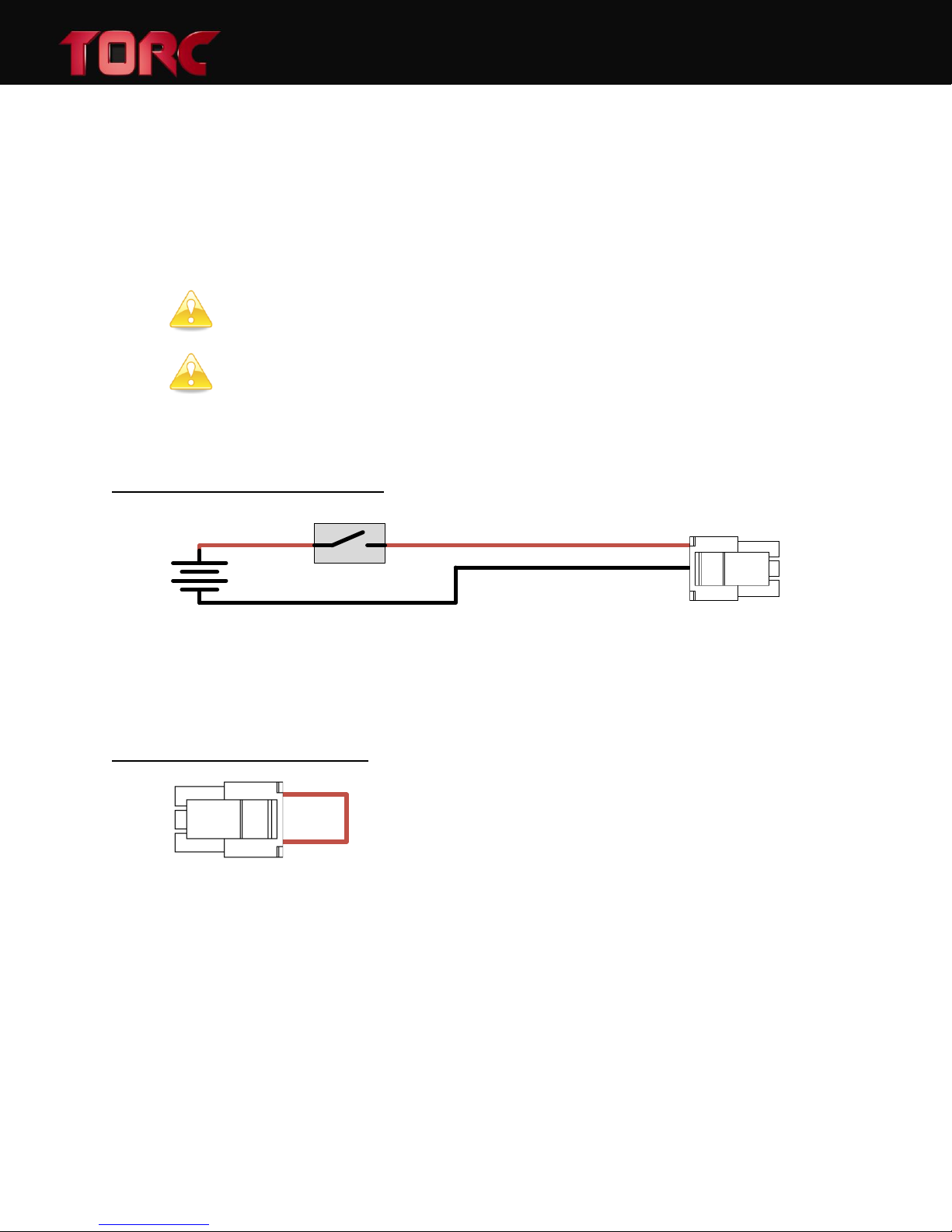
The remote enable connection is used to transition the PowerHub from a low power disabled
state to an active state. To enable the PowerHub, this input needs to be connected to a voltage
between 2-60 Vdc in reference to ground (Pin 2 of the Remote Enable Connector). When left
disconnected, the PowerHub is in the disabled state. When the PowerHub is disabled, all
outputs and communications are inactive.
EXAMPLE CONFIGURATION
PowerHubTM User Manual, Version 1.2
Figure 10: Remote enable configuration example – vehicle key switch
The accessory line of a vehicle key switch can be a used as a convenient remote enable input to
the PowerHub. In this configuration, the PowerHub is enabled when the key is in the ACC
position and disabled when the vehicle is turned off.
JUMPER CONFIGURATION
Figure 11: Remote Enable Jumper
A remote enable jumper is included with the PowerHub. When the jumper is in place, the
PowerHub will auto-enable any time power is supplied to the input connector. The PowerHub
will not go into low power state with the jumper installed.
8 PHYSICAL DIMENSIONS AND MOUNTING
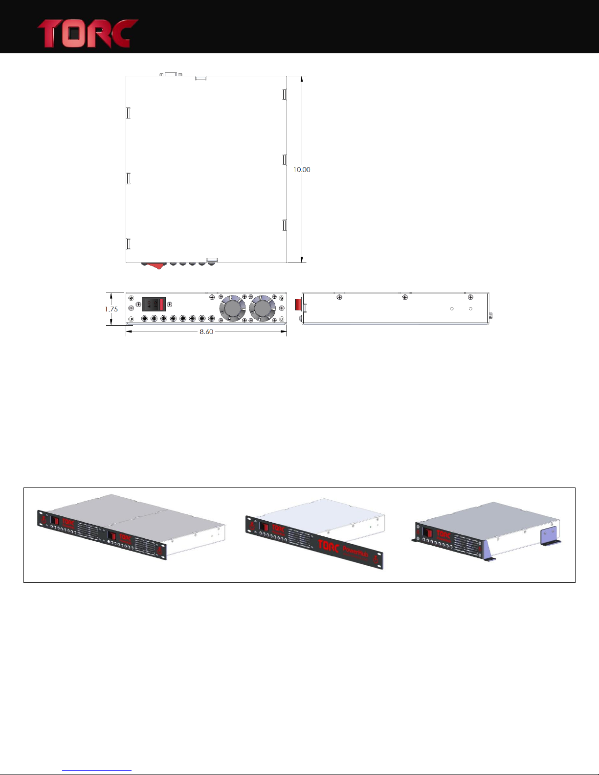
The slim form factor of the PowerHub Series of managed power distribution modules provides a
compact solution that is easily integrated into new or existing designs. A dimensioned outline
drawing of the PowerHub is included as Figure 12.
23
Page 25
PowerHubTM User Manual, Version 1.2
Figure 12: The physical dimensions of the base PowerHub module.
The PowerHub is designed to be mounted using one of several faceplate mounting options.
Faceplates are available for side-by-side rack mount, single rack mount, and standalone
configurations. Figure 13 shows the PowerHub in each one of these mounting arrangements.
The side-by-side rack mount option allows two PowerHub devices to occupy just one unit of
space in a standard 19 inch computing rack. If an odd number of PowerHub units are desired, a
single PowerHub faceplate is available which also occupies one unit in a 19 inch rack. Finally, if a
rack mount configuration is not desired, a standalone mounting kit is available.
Figure 13: The PowerHub shown with different mounting options.
8.1 Rack mount Faceplate Dimensions
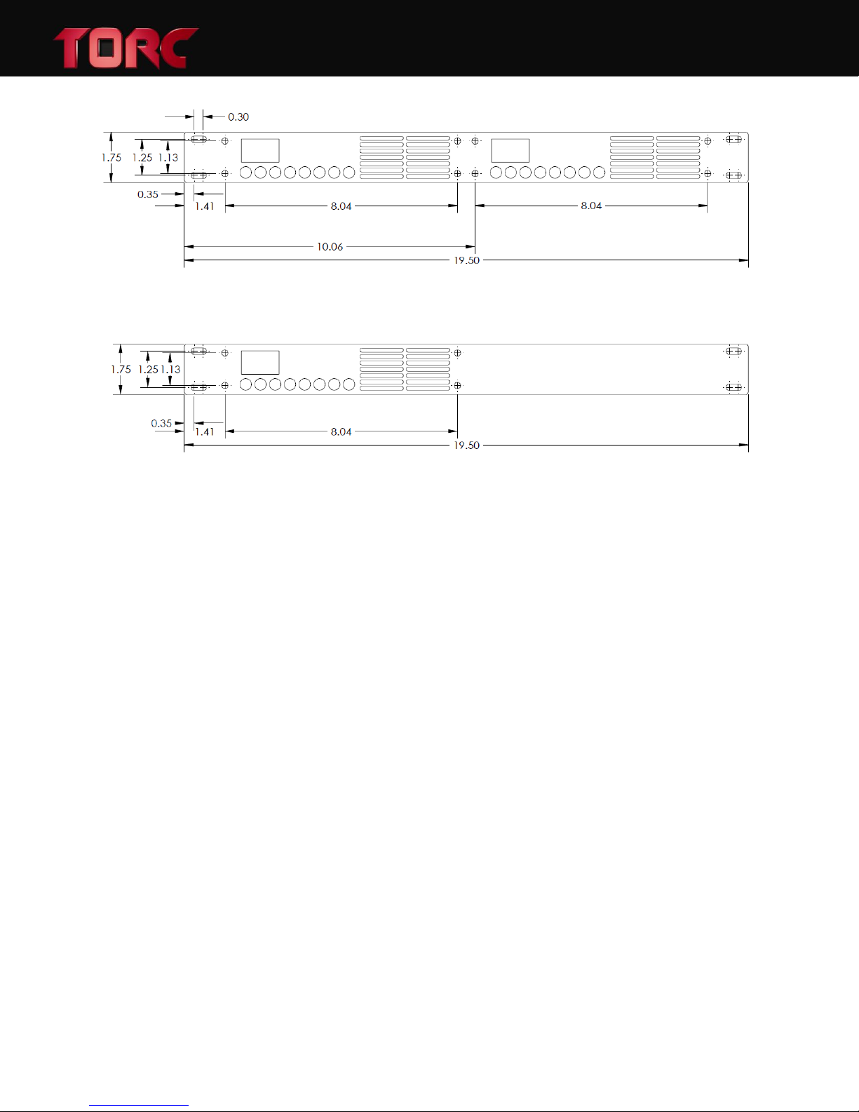
The rack mount faceplates are designed to occupy one unit of a standard 19 inch computer rack.
Dimensioned drawings of the rack mount faceplate options are included in Figure 14 and 15.
24
Page 26
PowerHubTM User Manual, Version 1.2
Figure 14: Dimensioned side-by-side rack mount faceplate drawing.
Figure 15: Dimensioned single rack mount faceplate drawing.
25
Page 27
8.2 Standalone Mounting Configuration
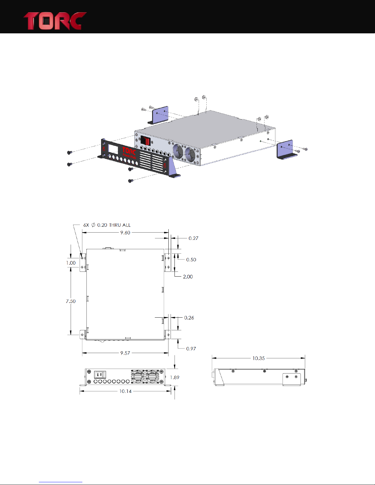
A standalone mounting configuration option is available if rack mounting is not desired. Figure
16 shows an exploded assembly view of this option. A dimensioned drawing, showing mounting
locations is given in Figure 17.
Figure 16: Exploded assembly of the standalone PowerHub mounting option.
PowerHubTM User Manual, Version 1.2
Figure 17: Dimensioned drawing of the standalone PowerHub mounting option.
26
Page 28

9 LIMITED WARRANTY
TORC Technologies, LLC (herein referred to as TORC) guarantees that the product(s) you have
purchased from TORC are free from defects in materials or workmanship for a period of one
year from the original date of purchase. Within this period TORC will, at its sole discretion,
repair or replace any components which fail under normal use. This warranty does not cover
failures due to abuse, misuse, accident, or unauthorized alterations or repairs.
There are no other warranties, expressed or implied, which extend beyond the description
contained herein including the implied warranty of merchantability and fitness for a particular
purpose. TORC expressly excludes all other warranties
TORC’s liability is limited to the cost of repair or replacement of the product. Such remedy shall
be the sole and exclusive remedy for any breach of warranty.
TORC shall not be liable for:
PowerHubTM User Manual, Version 1.2
1. Damage to other property caused by any defects in the product, damages based upon
inconvenience, loss of use of the product, loss of time, loss of profits, loss of business
opportunity, loss of goodwill, interference with business relationships, or other
commercial loss, even if advised of the possibility of such damages.
2. Any indirect or other damages, whether incidental, consequential, or otherwise.
3. Any claim against the customer by any other party.
The PowerHub firmware incorporates portions of the lwIP TCP/IP networking stack, originally
developed by Adam Dunkels at the Swedish Institute of Computer Science. The source code and
full text of the associated license agreement may be downloaded from
http://savannah.nongnu.org/projects/lwip.
27
 Loading...