

Page 1
Quickstart Guide
TCS series
TCS Series Quickstart Guide - Page - 1
Models covered by this Quick Start Guide
TCS-61, TCS-122, TCS-152, TCS-1561, TCS-B15A, TCS-B15B, TCS-B218
Thank you for choosing a TURBOSOUND loudspeaker product for your application. If you would like further information about
this or any other TURBOSOUND product, please contact us by phone at +44 (0)1562 732299 or visit our website at
www.turbosound.com.
Unpacking the Loudspeaker
After unpacking the unit please check carefully for damage. If damage is found, please notify your supplier at once. You, the
consignee, must instigate any claim. Please retain all packaging in case of future re-shipment.
System Requirements – Passive, Bi- amped and Tri-amped Loudspeakers
The TCS-61 two-way loudspeaker operates as a passive system and requires only one
amplifier channel for correct operation; the frequency splitting between the LF driver
and the HF driver being accomplished by the internal passive crossover network built
into each enclosure. It is equipped with a Neutrik speakON NL4 wired in parallel with
a 4-way barrier strip connector, providing input and loop-through connections to
additional TCS series loudspeakers.
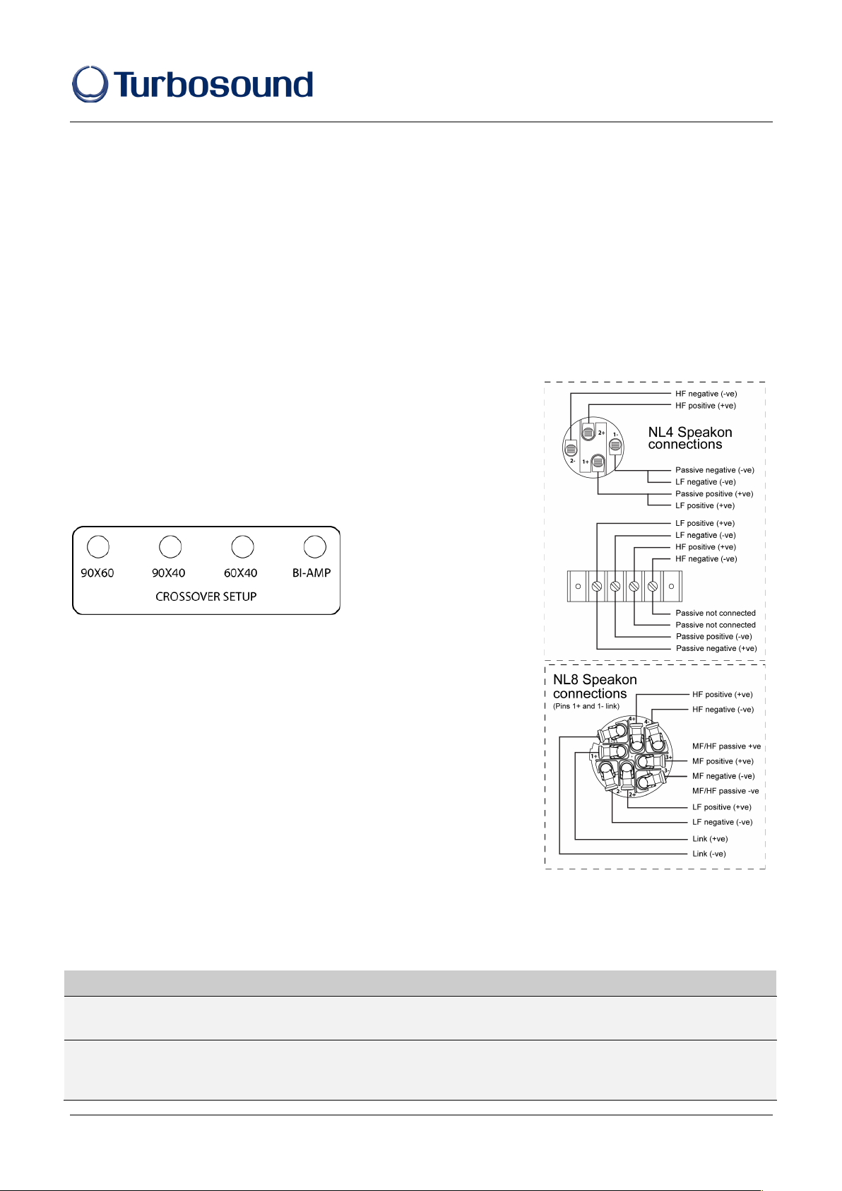
The TCS-122 and TCS-152 will operate either in bi-amp mode; or in one of three
passive modes in which minor voicing adjustments are made within the crossover
network depending on the
supplied HF horn option, as
indicated by the position of the
internal jumper on the crossover
setup section of the connector
panel shown here (all models are
shipped by default in passive mode). They are each equipped with a Neutrik speakON
NL4 connector wired in parallel with a 4-way barrier strip. The TCS-122 and TCS-152
two-way loudspeakers in bi-amped mode require two amplifier channels and an
external electronic crossover.
The TCS-1561 is a switchable bi-amp/tri-amp loudspeaker (shipped as bi-amp)
requiring either two or three amplifier channels, together with an electronic
crossover. All connections are provided on two parallel-linked Neutrik speakON NL8
connectors.
To avoid wasting amplifier power you should use heavy-duty speaker cable with a
minimum wire size of 12 gauge (1.5mm²), and preferably 10 gauge (2.5mm²) for
longer runs. For extreme cable lengths be aware of cable impedance and resistive
losses. Always observe the correct polarity as shown.
Amplifier considerations
TCS series speaker enclosures should be driven by high quality power amplifiers designed for true professional use. Amplifiers
should be capable of delivering long term broadband power equal to the loudspeaker’s program power rating at its
stated nominal impedance. The use of under-powered amplifiers must be avoided as heavily clipped signals can cause
permanent loudspeaker damage.
Model&
TCS*61&
TCS*122&
TCS*152&
TCS*1561&
TCS*B15A&
TCS*B15B&
TCS*B218&
Impedance&
8Ω"
HF:8Ω,"LF:8Ω"
LF:8Ω,"HF:8Ω"
HF:16Ω,"MF:16Ω,"LF:8Ω"
Passive:12Ω"
8Ω"
8Ω"
4Ω"
Amplifier&
power&
350w"
HF:200w"
LF:1000w"
HF:200w"
LF:1000w"
HF:100w"
MF:200w"
LF:1000w"
1000w"
1000w"
2400w"
Page 2

Quickstart Guide
TCS series
TCS Quickstart Guide - Page - 2
System controllers with bi- amplified and tri-amped systems
These systems must be used with Turbosound LMS-D24 or LMS-D26 controllers, since these provide vital operating and system
security features. If you do not have a controller, DO NOT USE the loudspeaker without one; please contact your Turbosound
dealer for further details.
Turbosound LMS-D2X controllers provide factory presets for all TCS systems, as well as additional user program slots.
1. Power up the controller(s) and associated power amplifiers.
2. Press RECALL to select the appropriate program from the preset menu using the ‘A’ ROTARY ENCODER.
3. Press RECALL again to accept the preset. The controller will un-mute and is then ready for use.
Self-powered loudspeakers
Powered TCS loudspeakers feature very efficient integrated Class D amplifiers and control electronics modules, providing a
completely self-contained professional sound system. The XLR inputs and outputs are electronically balanced and are wired pin 2
hot, pin 3 cold, pin 1 ground. Amplifiers will operate over a range of mains input voltages from 100V to 240V AC without
adjustment.
1. Connect the mains power using the supplied powerCON mains connector.
2. Connect the signal input from a professional mixing console to the female XLR input, and link out to additional powered
loudspeakers from the male XLR output if required
3. Power up the loudspeaker. After a short self-test routine the loudspeaker will un-mute; it is now ready for use.
Networking capability
TCS systems are designed to offer control and monitoring of system parameters over a BvNet network in real time using a PC and
TurboDrive software. LMS-D2X controllers are equipped with network cards and are pre-configured with factory programs for all
TCS series models. Self-powered TCS loudspeakers have built-in network functionality on RJ45 connectors.
Download the TurboDrive software from the supplied CD or from www.turbosound.com and follow the installation
instructions.
Install the drivers. If connecting via RS232 there is no need to install drivers. If connecting via USB install the USB drivers
which can be found on the CD that came with your Linea Research USB interface.
Networking multiple devices to a PC: BvNet is the method of connecting multiple devices – these can be controllers and/or
powered TCS loudspeakers – and this is done with the Linea Research USB & RS232 Interface (available from Turbosound). The
interface enables devices to be connected to a PC either using RS232 or using USB. EIA485 is the network protocol among the
networked devices and is carried over CAT5-type cables. Minimum system requirements are: PC with Pentium processor,
Windows NT, 2000, XP, or Vista, CD ROM drive or internet access, RS232 or USB port.
RS232: Connect your computer to the BvNet interface using a standard 9-pin serial cable. External power is required for RS232
operation and this should be supplied by the Linea Research Accessory Power Supply.
USB: Connect your computer to the BvNet interface using a USB Type A to USB Type B cable. External power is not required
when using USB.
Connect networked devices via RJ45 CAT5 cables.
Launch the TurboDrive software.
Application Authorisation: TurboDrive prompts for an Authorisation Code on the first launch which is PJLUWZ.
Select the COM port from Network > Com Port.
Click the Online toolbar button.
Click on one of the devices that appear in the tree view to Launch the panel.
When the progress bar indicates
ready,
adjust the controls as required.
Please refer to the TurboDrive User Guide for further information on networking.
Page 3
Quickstart Guide
TCS series
TCS Series Quickstart Guide - Page - 3
Mounting and Fixing
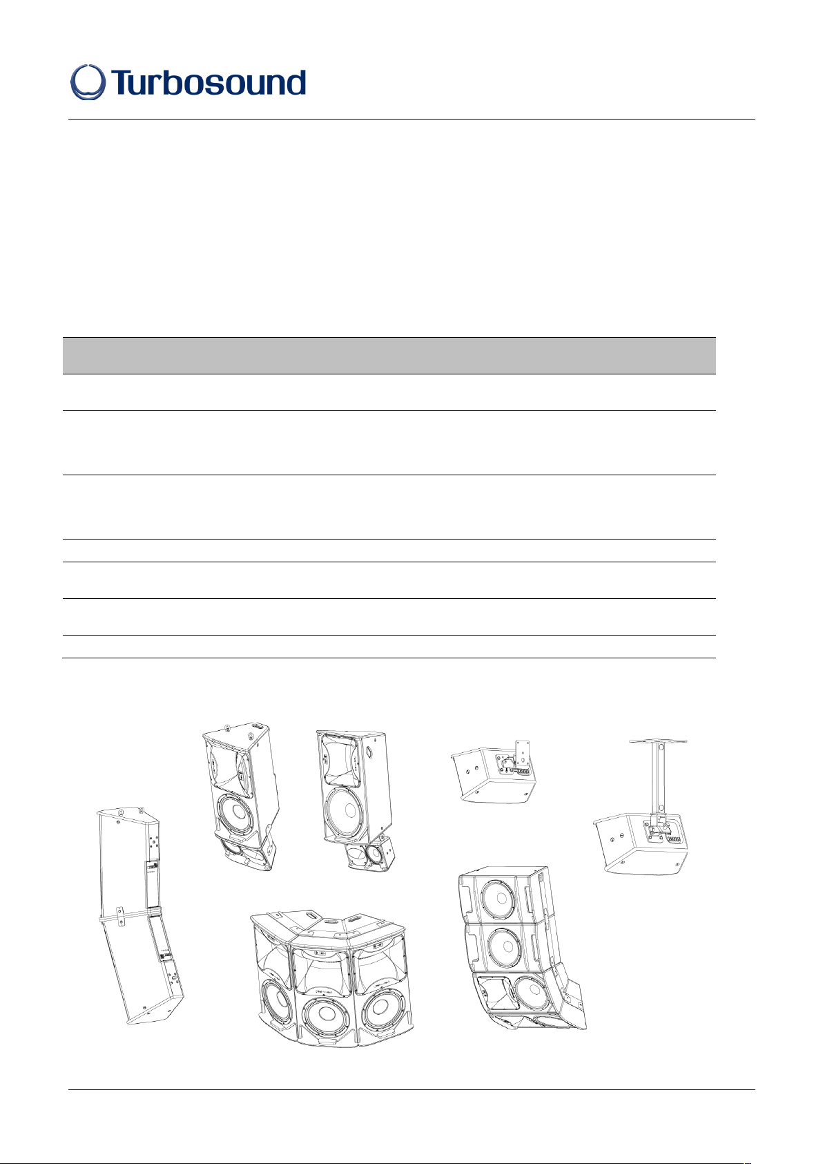
The table below summarises the rigging parts or kits required for various applications, and some examples of the possible rigging
options are illustrated.
CS series cabinets are designed with multiple internal rigging points to suit many possible mounting methods in permanent
installations. All cabinets can be simply suspended using optional M8 or M10 shoulder eyebolts coupled to the internal rigging
points provided. Remove the appropriate countersunk screws and replace them with eyebolts, which must have a thread length of
at least 18mm. Use the rear rigging point to angle the cabinet for optimum room coverage. Cabinets may be hung upside down if
required. Turbosound WB-20, WB-55 and CB-55 wall and ceiling brackets are optionally available for TCS series cabinets, and
these are also compatible with OmniMount wall and ceiling brackets which use 60mm x 60mm hole spacing.
Model
Wall
Ceiling
Downfill
Vertical
Array
Horizontal
Array
Eyebolts
TCS-61
WB-20
CB-55
SB-61
ICC-61
EB-8
TCS-122
WB-55
CB-55
FP-1
ICC-2V
ICC-2H
ICC-6H
FP-1
ICC-2H
EB-10/18
TCS-152
WB-55
CB-55
FP-1
ICC-2V
ICC-3H
ICC-5H
FP-1
ICC-2H
EB-10/18
TCS-1561
ICC-2V
EB-10/18
TCS-B15A
FP-2
ICC-4H
EB-10/18
TCS-B15B
FP-2
ICC-4H
EB-10/18
TCS-B218
EB-10/18
Some typical examples of the possible rigging options are shown here:
Page 4
Quickstart Guide
TCS series
TCS Quickstart Guide - Page - 4
TCS Series Flying Components
Wall and Ceiling Brackets
To install a loudspeaker using Turbosound wall and ceiling brackets, first separate the brackets into their wall/ceiling plate and
speaker plate component parts. Remove the countersunk bolts on the rear panel of the cabinet. Attach the speaker plate to the
cabinet with the bolts supplied. Fix the wall/ceiling plate in the venue using appropriate fixings (not supplied). Lift the loudspeaker
on to the wall plate and re-assemble the bracket parts, adjust the vertical angle and tighten all bolts.
Downfill Applications
The TCS-61 can be tight-packed underneath a TCS-152 cabinet to provide downfill coverage
using the SB-61 swivel bracket. First disassemble the swivel bracket into its component
parts. Remove the countersunk bolts from the bottom panel of the TCS-152 cabinet and fit
the section with the elongated holes using the fixings supplied. Remove the countersunk
bolts on the top panel and fit the swivel bracket using the supplied fixings. Re-assemble the
swivel bracket, angle as appropriate and tighten all fixings.
For downfill applications under TCS-122 cabinets use two ICC-61 inter-cabinet couplers.
Remove the four countersunk screws located on the sides of the TCS-61
To use the SB-61 to install the TCS-61 in a ceiling-mount application, separate the
component parts as above, and fix the top section to the ceiling with appropriate fixings (not
supplied). Fit the other half to the TCS-61 cabinet, re-assemble the bracket, angle as
appropriate and tighten all fixings.
Loudspeaker Arrays and Clusters
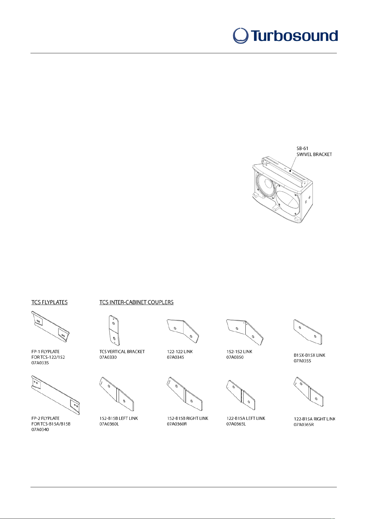
An array of two or more cabinets requires the use of kits of flyplates and inter-cabinet couplers, which are fixed to the cabinet
sides through the M10 rigging points and assembled together in a ‘daisy chain’ fashion to build up the required array. For all
loudspeaker arrays consisting of two or more cabinets the number of flying kits required = the number of boxes – 1.
Illustrated here are the components parts available for TCS cabinets:
Page 5
Quickstart Guide
TCS series
TCS Series Quickstart Guide - Page - 5
TCS series Flying Kits
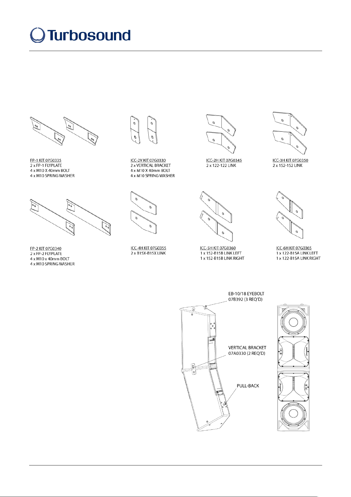
Flying components are arranged into kits as shown here:
Vertical Arrays
The simplest vertical array consists of two TCS-122 cabinets
or two TCS-152 cabinets flown one above the other and
suspended from eyebolts. The upper box can be inverted in
order to close-couple the HF horns if required as shown
here.
07G0330 ICC- 2V kit of two (2) vertical brackets,
includes 4 x M10 x 40mm bolts and 4
x M10 spring washers
07B392 EB- 10/18 M10 shoulder eyebolts (3 required)
• Position the cabinets as you would like the cluster to
be assembled. Remove countersunk screws as
appropriate from the sides of each cabinet, and fit a
07A0330 vertical bracket on each side between the two
cabinets using the fixings provided.
• Remove the countersunk screws from the top of the
upper cabinet and fit M10 shoulder eyebolts.
• Use the lower rear eyebolt point as a pull-back to
create the required cluster inclination.
Page 6
Quickstart Guide
TCS series
TCS Quickstart Guide - Page - 6
Vertical Arrays with Bass Cabinets
Bass cabinets can be integrated into larger arrays using the same type of flying kits as shown on the array of TCS-B15B and TCS152 cabinets illustrated here.
07G0340 FP- 1 kit of two (2) FP-1 flyplates for TCS-122 or TCS-152 mid/high cabinets, includes 4 x M10 x 40mm bolts and 4
x M10 spring washers
Downfill Applications
The TCS-61 can be tight-packed underneath a TCS-152 cabinet to provide downfill coverage using the SB-61 swivel bracket.
First disassemble the swivel bracket into its component parts. Remove the countersunk bolts from the bottom panel of the TCS152 cabinet and fit the section with the elongated holes using the fixings supplied. Remove the countersunk bolts on the top panel
and fit the swivel bracket using the supplied fixings. Re-assemble the swivel bracket, angle as appropriate and tighten all fixings.
For downfill applications under TCS-122 cabinets use two ICC-61 inter-cabinet couplers. Remove the four countersunk screws
located on the sides of the TCS-61
To use the SB-61 to install the TCS-61 in a ceiling-mount application, separate the component parts as above, and fix the top
section to the ceiling with appropriate fixings (not supplied). Fit the other half to the TCS-61 cabinet, re-assemble the bracket,
angle as appropriate and tighten all fixings.
Horizontal Arrays / Centre Clusters
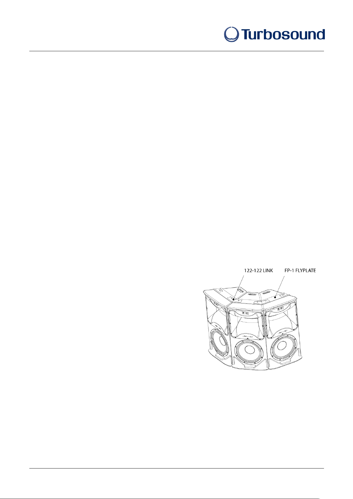
As with vertical arrays, clusters are assembled using kits of flyplates and couplers.
07G0335 FP-1 KIT kit of two (2) FP-1 flyplates (one top, one bottom) for each TCS-122 or TCS-152 mid/high
includes 4 x M10 x 40mm bolts and 4 x M10 spring washer
07G0345 ICC- 2H kit of two (2) 122-122 links between each TCS-122 or TCS-152 mid/high
includes 4 x M10 x 40mm bolts and 4 x M10 spring washer
07B393 EB- 10/18 three (3) M10 x 18mm shoulder eyebolts
• Remove the countersunk screws from the rigging points on the
bottom of the cabinets. Fit the FP-1 flyplates and 122-122 links
using the fixings provided and tighten all fixings.
• Invert the cluster and fit the corresponding FP-1 flyplates and
122-122 links to the top of the cabinets, replacing two of the M10
screws with M10 x 18mm shoulder eyebolts fitted to the inner
rigging points on the two outside cabinets.
• Lift the cluster using the eyebolts and tilt back using the third
M10 eyebolt attached to the lower rigging point on the back of
the centre cabinet.
IMPORTANT NOTE: The rigging of a flown sound system may be dangerous unless undertaken by qualified personnel with the
required experience and certification to perform the necessary tasks. Fixing of hanging points in a roof should always be carried
out by a professional rigger and in accordance with the local rules of the venue. Walls, floors or ceilings must be capable of safely
and securely supporting the actual load. The rigging accessory used must be safely and securely fixed both to the loudspeaker
and to the wall, floor or ceiling.
When mounting rigging components on walls, floors or ceilings, ensure that all fixings and fasteners used are of an appropriate
size and load rating. Wall and ceiling claddings, and the construction and composition of walls and ceilings, all need to be taken
into account when determining whether a particular fixing arrangement can be safely employed for a particular load. Cavity plugs
or other specialist fixings, if required, must be of an appropriate type, and must be fitted and used in accordance with the maker’s
instructions.
Page 7
Quickstart Guide
TCS series
TCS Series Quickstart Guide - Page - 7
Rotating the HF horn pattern
The high frequency horn in all TCS-122 and TCS-152 models can be rotated through 90° in order to swap the horizontal and
vertical dispersion patterns, particularly useful when assembling clusters or for example to retain the original dispersion when the
cabinet is installed in a horizontal orientation.
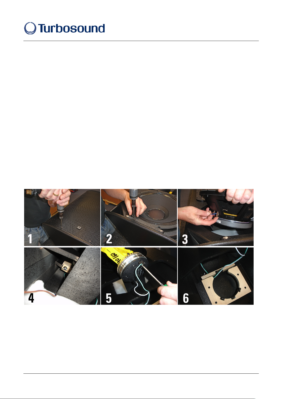
1. Place the cabinet on its back on a suitable work surface. Remove the four pan-head posidrive screws that hold the grille in place
and set the grille aside (fig 1).
2. Remove the bass driver and horn fixings screws (fig 2).
3. Disconnect and remove the bass driver, making a note of the polarity for later reconnection (fig 3).
4. Loosen the two wing nuts securing the hf driver retaining brace and lift out the horn and compression driver assembly (fig 4).
5. If required for servicing or replacement, disconnect the cables from the compression driver, making a note of the polarity for
later reconnection (fig 5).
6. Rotate the horn to achieve the desired coverage pattern and replace it in the cabinet (fig 6).
7. If the compression driver has been removed, reconnect the cables observing the correct polarity (white cable to the +ve
terminal, green/white cable to the –ve terminal) (fig 5).
8. Replace the horn and driver in the cabinet, making sure that the cable passes underneath the driver retainer and the
compression driver locates squarely in the retaining brace (fig 6).
9. Tighten the wing nuts.
10. Replace the horn fixing screws and tighten.
11. Reconnect the bass driver, observing the correct polarity (brown cable to the red +ve terminal, blue cable to the black –ve
terminal) and reinstate the driver in the cabinet (fig 3). Replace and tighten the driver fixing screws (fig 2).
12. Replace the grille (fig 1) and phase check the cabinet before use.
Page 8

Quickstart Guide
TCS series
TCS Quickstart Guide - Page - 8
Spares and Accessories
CD-115 / RD-115 Compression driver / diaphragm for TCS-61, TCS-1561
CD-213.2/RD-213.2 Compression driver / diaphragm for TCS-122, TCS-152
LS-6508 6.5” low frequency loudspeaker for TCS-61
LS-6505 / RC-6505 6.5” mid frequency loudspeaker / recone kit for TCS-1561
LS-1222 / RC-1222 12” low frequency loudspeaker / recone kit for TCS-122
LS-1529 / RC-1529 15” low frequency loudspeaker / recone kit for TCS-152, TCS-1561, TCS-B15A, TCS-B15B
LS-1814 / RC-1814 18” low frequency loudspeaker / recone kit for TCS-B218
LIMITED WARRANTY
For full details of the comprehensive Turbosound warranty please visit www.music-group.com/warranty
TURBOSOUND
MUSIC Group Research UK Limited, Klark Industrial Park, Walter Nash Road, Kidderminster, Worcestershire DY11 7HJ, UK
tel: +44(0)1562 732299 www.turbosound.com
tcsquickstart v2.0
 Loading...