

Toray TMR140 Series, TMR140-100S, TMR140-050S, TMR140-200D, TMR140-200W Instruction Manual
Submerged Membrane Module
for MBR
TORAY “MEMBRAY”
“TMR140 Series”
Instruction Manual
Toray Industries, Inc.
Water Treatment Division
8-1, Mihama 1-chome, Urayasu, Chiba 279-8555 Japan
Tel: +81-47-350-6223
Fax: +81-47-350-6066
URL: http:// www.toray.com
Published: February 2008
AIRE-064-1-4

Content
I. Introduction ........................................................................................................................................1
1. Features of MBR.......................................................................................................................... 1
2. Outline of “TMR140 Series” ......................................................................................................... 2
II. FOR SAFE OPERATION OF “TMR140 Series” ............................................................................ 5
1. Unpacking and Installation...........................................................................................................5
2. Operation and Maintenance......................................................................................................... 6
3. Chemical Cleaning of Element..................................................................................................... 7
III. SPECIFICATIONS AND PERFORMANCE OF “TMR140 SERIES”..............................................9
1. Specifications of Element.............................................................................................................9
2. Specifications of Polyurethane Permeate Tube........................................................................... 9
3. Specifications and Performance of “TMR140 Series” Module................................................... 10
IV. MEMBRANEFILTRATION PROCESS DESIGN FOR “TMR140 SERIES”.................................. 12
1. Standard Time Chart.................................................................................................................. 12
2. Flow Diagram of Membrane Filtration........................................................................................ 12
3. Layout of “TMR140 Series” Modules in Membrane Submerged Tank......................................17
4. Piping ......................................................................................................................................... 20
V. Installation of “TMR140 Series” ........................................................................................................ 22
1. Preparatory Procedure............................................................................................................... 22
2. Unloading Products....................................................................................................................22
3. Checking Products..................................................................................................................... 22
4. Storage Products ....................................................................................................................... 23
5. Installation Products...................................................................................................................23
VI. Start of Operation.............................................................................................................................27
1. Clean Water Operation .............................................................................................................. 27
2. Seeding Sludge Injection ........................................................................................................... 28
3. Actual Filtration Operation..........................................................................................................28
VII. Operation Control.........................................................................................................................29
1. Standard Operating Conditions.................................................................................................. 29
2. Operating Parameters................................................................................................................31
3. Daily Inspection..........................................................................................................................32
VIII. Maintenance of “TMR140 Series”................................................................................................ 34
1. Maintenance Items and Maintenance Frequency......................................................................34
2. Air Diffuser Cleaning..................................................................................................................35
3. Chemical Cleaning of Element................................................................................................... 35
3. Chemical Cleaning of Element................................................................................................... 36
4. Chemical Agents Used for Chemical Cleaning.......................................................................... 36
5. Handling of Chemical Agents..................................................................................................... 37
6. Chemical Cleaning Procedure...................................................................................................40
7. Lifting Procedure........................................................................................................................ 43
IX. Replacement Parts List................................................................................................................ 44
IIX. Troubleshooting............................................................................................................................ 45
AIRE-064-1-4

Symbols used in this manual
DANGER
!
This symbol is used to indicate an imminent hazardous situation
which, if not avoided, will result in serious injury or death.
WARNING
!
CAUTION
!
This symbol is used to indicate a potentially hazardous situation
which, if not avoided, can result in serious injury or death.
This symbol is used to indicate a potentially hazardous situation
which, if not avoided, may result in injury or property damage.
AIRE-064-1-4
I. Introduction
TORAY "MEMBRAY" is the submerged membrane module suitable for the membrane
bioreactor (MBR) that has been developed based on the polymer science and the membrane
fabrication technologies accumulated for a long time in Toray Industries, Inc.
"TMR140 Series" is a standard model of "MEMBRAY". This manual explains MBR's features
and describes the specifications of "TMR140 Series" and its safe operations including
installation, operation, maintenance procedures and peripheral equipments. Operators
should thoroughly read this manual to ensure stable operation.
1. Features of MBR
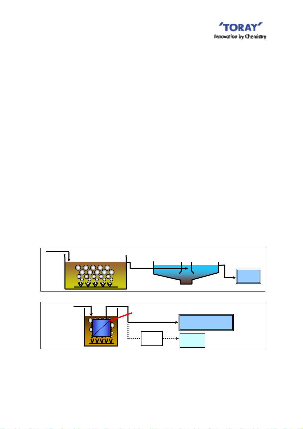
The process flow of the conventional activated sludge method (ASM) and MBR are shown in
Fig.I-1 and Fig.I-2, respectively. Unlike ASM, which employs the sedimentation tank, MBR
separates sludge with membranes. MBR provide the following advantages:
(1) Small Footprint
In the case of MBR, the biological treatment can be operated at higher MLSS, so the
aeration tank is reduced. And MBR does not need a sedimentation tank. As a result, MBR
provides smaller footprint of the plant.
(2) High quality of treated water
MBR removes suspended solid (SS) from the sludge liquid with membrane much more
certainly than conventional sedimentation process. MBR also rejects microorganisms such
as Escherichia coli and Cryptosporidium efficiently.
Waste
water
Waste
water
Membrane
Submerged
Tank
Aeration Tank
Fig. I-1 ASM Flow
Submerged membrane
module
RO
membrane
Sedimentation tank
Discharge
Discharge or Reuse
Reuse
Fig. I-2 MBR Flow
1
AIRE-064-1-4
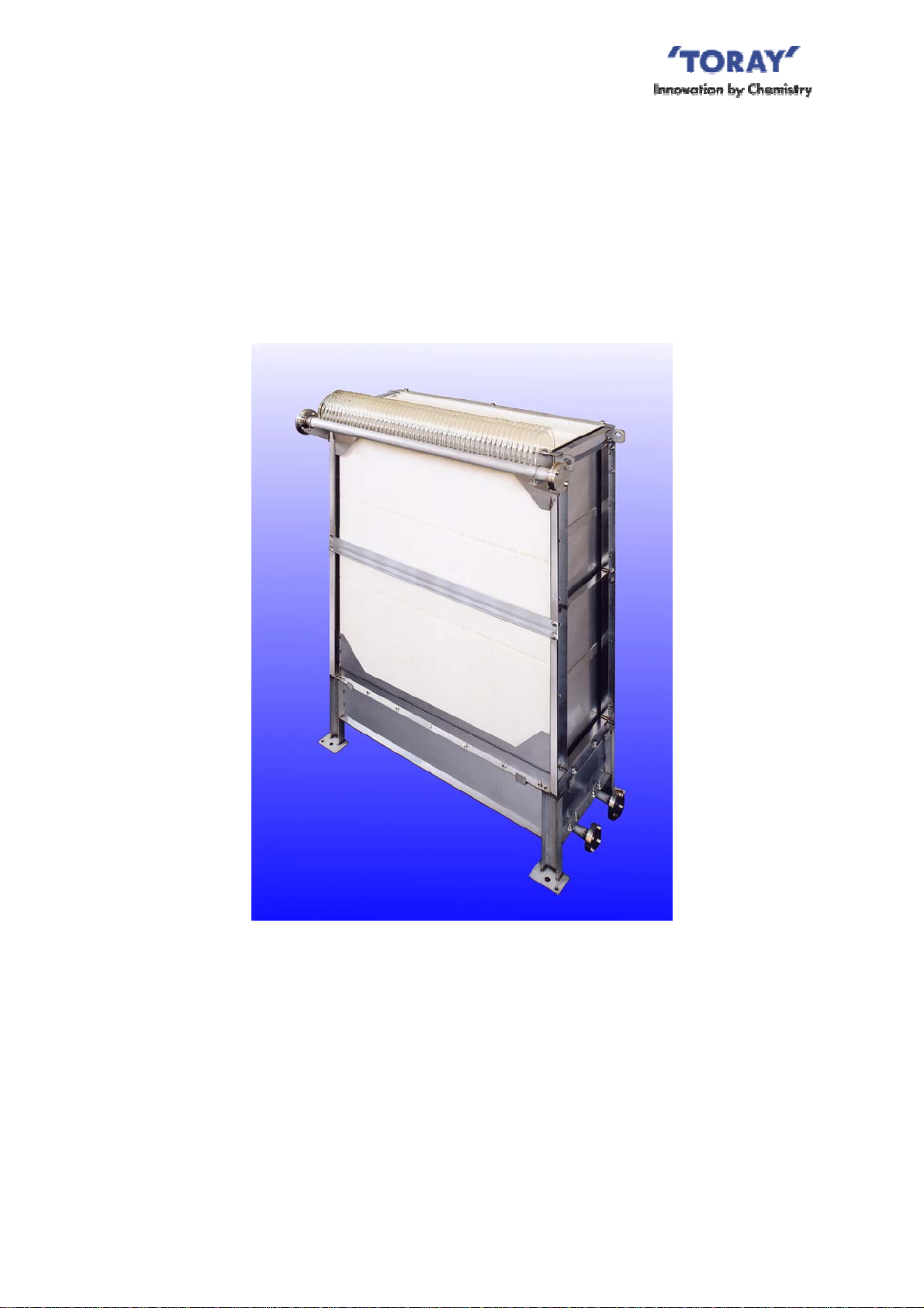
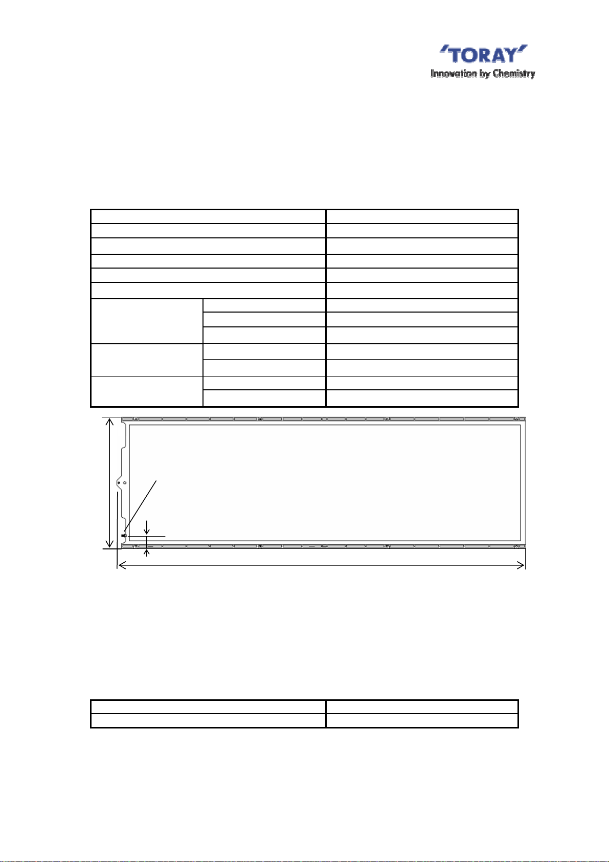
2. Outline of “TMR140 Series”
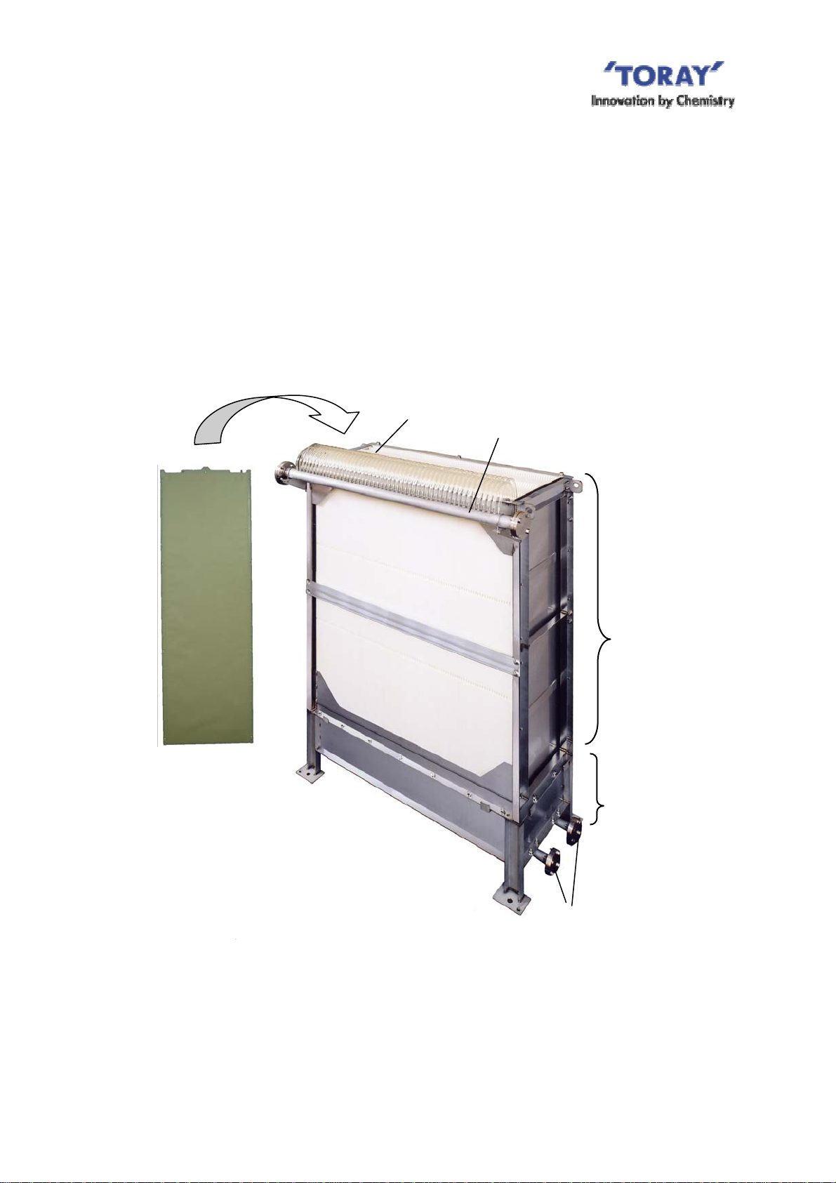
TMR140 Series” is the membrane module composed of the element block and the aeration
block. The element block contains a number of membrane elements stacked at equal
clearance, each of which has flat sheet membranes attached on both sides of ABS panel.
Each element is connected via polyurethane tube to the permeated water manifold. The
aeration block consists of coarse-bubble air diffusers to supply scouring air (see Fig.I-3).
This module is used submerged in sludge liquid.
The following shows the features of “TMR140 Series”.
Tube
Permeated water Manifold
Element
Element block
Aeration block
Coarse Air
diffuser
Fig. I-3 Appearance of “TMR140-100S”
2
AIRE-064-1-4
o
e
m
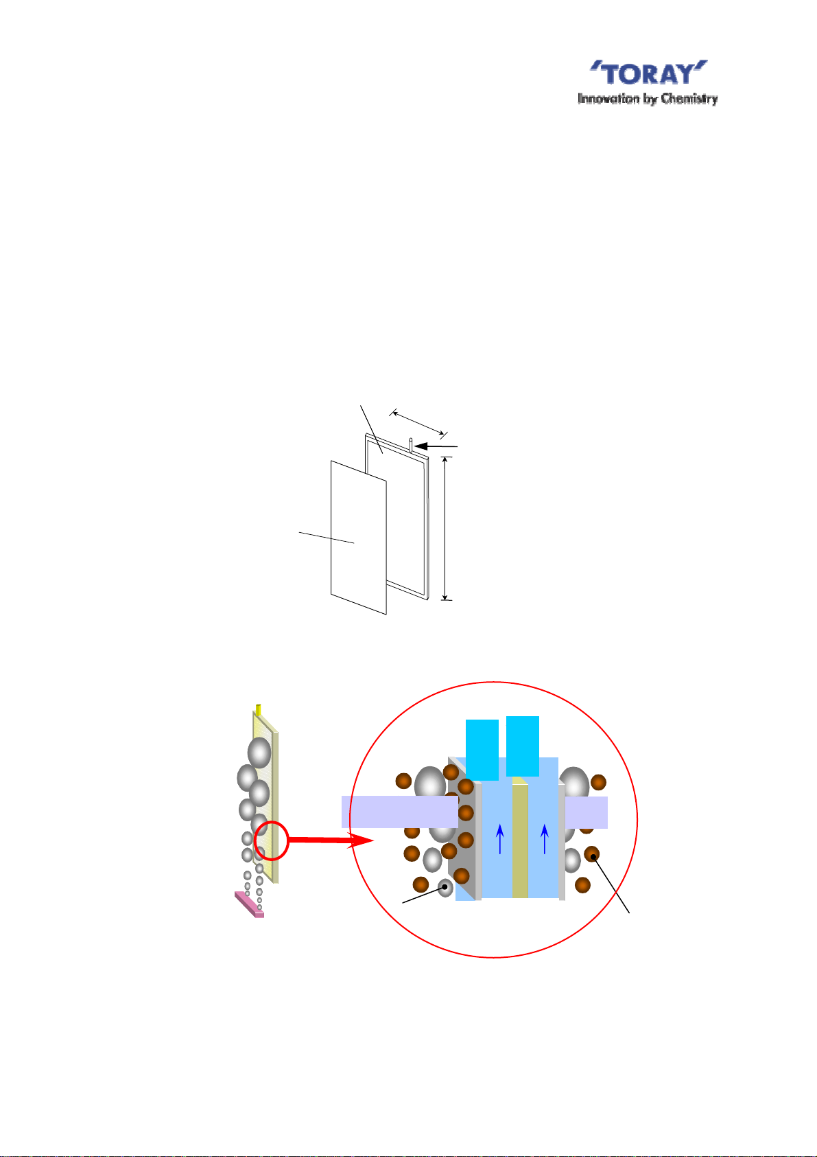
(1) Shape of Element
The membrane element is a flat sheet type as shown in Fig.I-4. At the normal filtration
operation, the sludge accumulated on the membrane surface is cleaned up effectively with
upward water stream generated with the scouring air supplied from the air diffusers installed
at the bottom side (Fig.I-5). This mechanism ensures stable filtration, since the membrane
does not easily admit of sludge adherence to its surface.
In addition, thanks to the long element design (1.6 m), a larger membrane area is achieved
per footprint, allowing effective use of diffused air.
Supporting panel
0.5
Permeated Water
N
zzl
Membrane
1.6 m
Fig. I-4 Structure of Element
Element
Permeated
water
Air
Air
Membrane
Supporting
panel
Membrane
Activated sludge particle
Fig. I-5 Filtration Principle of Activated Sludge
AIRE-064-1-4
3
東
クボタ
東
クボタ
N
(2) Membrane Structure
The flat sheet membrane consists of PVDF (Polyvinylidene Fluoride) functional layer and the
base layer of PET (polyester) non-woven fabric. This structure gives the membrane superior
physical strength and high chemical resistance.
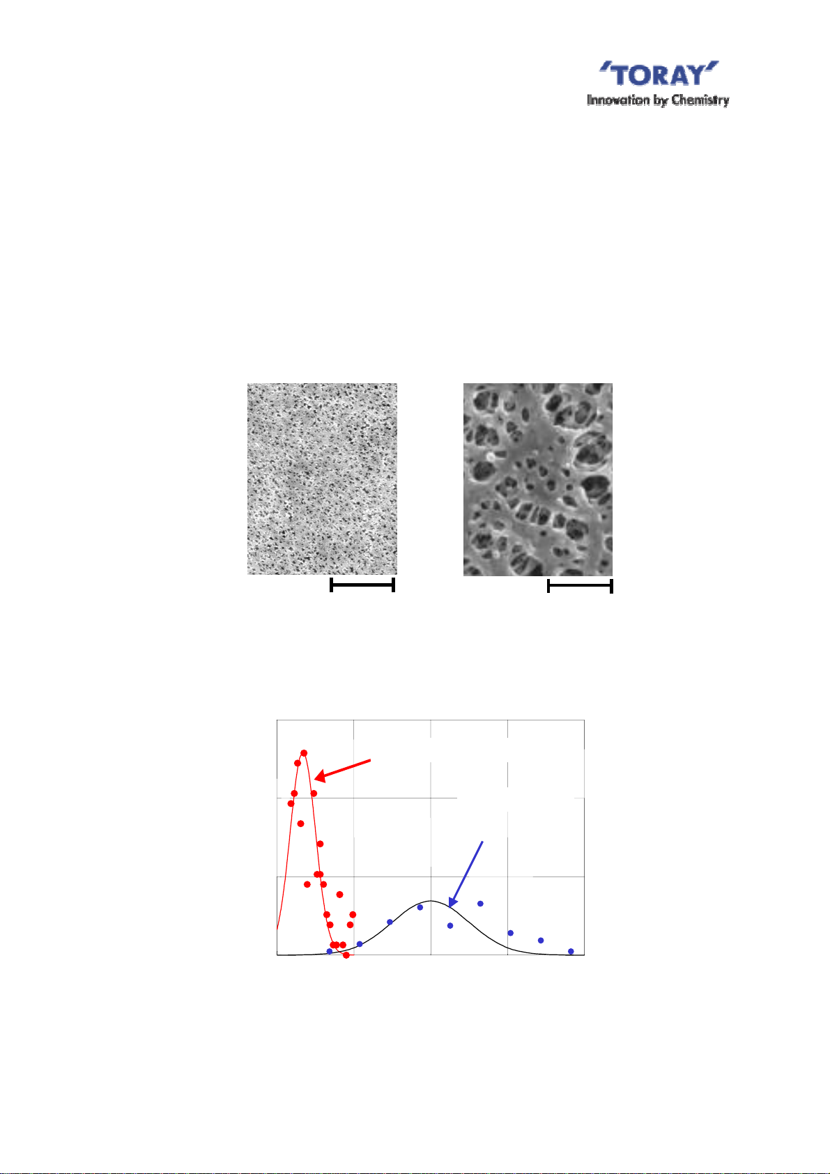
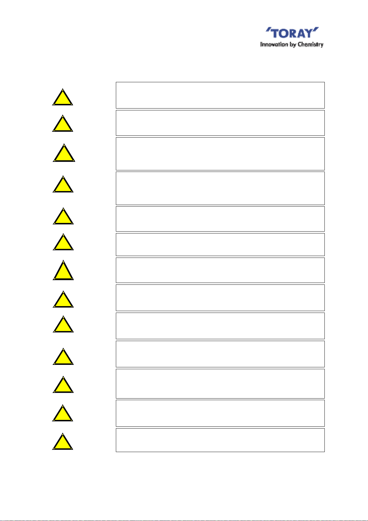
(3) Membrane Pore Size
Numerous small-size pores are distributed evenly over the membrane surface with a sharp
pore-size distribution. This structure gives an outstanding high treated water quality and an
excellent water permeability, making the membrane highly resistant to clogging (see Fig.I-6
and Fig.I-7) compared to other membranes. The average pore size is 0.08 micron meter.
Fig. I-6 Membrane Surface (photo)
1.5
)
2
/m
12
1.0
0.5
umber of pore (10
3.0 micron 3.0 micron
Other Membrane Toray PVDF Membrane
PVDF
TorayPVDF Membrane
Other Membrane
レ
レ
BF014
BF014
0
0
0.2 0.4
Pore Size (micron)
Fig. I-7 Pore Size Distribution
4
0.6 0.8
AIRE-064-1-4

II. FOR SAFE OPERATION OF “TMR140 Series”
Before using “TMR140 Series”, please thoroughly read this Instruction Manual and follow the
instructions described in this manual, especially the safety precautions shown below. The
details of each precaution are described in the relevant chapter
1. Unpacking and Installation
DANGER
!
DANGER
!
When lifting “TMR140 Series” or its part, please attach chains or
slings to it and raise it straight upward
shaking. Please never allow any person under lifted article.
Please use chains or slings compatible with lifting weight when
lifting "TMR140 Series" or its part.
calmly to prevent it from
DANGER
!
CAUTION
!
CAUTION
!
CAUTION
!
CAUTION
!
When installing “TMR140 Series” module, please set up a foothold
in advance. Please never climb the module. Please use protective
equipment to ensure the safety of workers.
At transportation, storage and installation, please take appropriate
measures to protect "TMR140 Series" or its part from damage.
Please don't put any heavy objects on the module. Please take
care to protect the module from collision with other objects.
Please do not leave "TMR140 Series" for hours in the place where
the temperature is higher than 40 degree C or in the place exposed
to direct sunlight.
Especially ABS supporting panel may be deteriorated with direct
sunlight, ultraviolet ray.
Please take adequate measures to protect “TMR140 Series” from
sparks caused by welding, fusion cutting or grinding throughout the
entire process from installation work to operation startup.
Please protect “TMR140 Series” from freezing at any time.
CAUTION
!
CAUTION
!
Please don't pressurize the permeate side of "TMR140 Series”.
Please install the screen with openings of 3.0 mm or under before
"TMR140 Series” or the membranes might be polluted and clogged
severely with foreign substances brought with the raw water.
AIRE-064-1-4
5
2. Operation and Maintenance
WARNING
!
WARNING
!
Don't use permeated water for drinking.
Before discharging the treated water to the environment or reusing
it, make sure to analyze its quality and confirm that the water
quality meets the intended purpose.
WARNING
!
CAUTION
!
CAUTION
!
CAUTION
!
CAUTION
!
CAUTION
!
CAUTION
!
Don't burn the membranes without appropriate facilities since
harmful Hydrogen fluoride (HF) gas is generated at burning.
When dispose membranes, please apply a service of a qualified
waste disposing company.
When the clean water operation, charging clean water to the
membrane submerged tank with the air discharge valve open to
release air from the elements. After charging water, close the air
discharge valve.
Don’t use the ground water, which contains considerable amount
of iron, manganese, calcium or silica, for the clean water operation
as it may cause the clogging of the membrane.
Don't continue the clean water operation unnecessarily.
A long-time filtration of clean water tends to cause the clogging.
Once the membrane gets wet, keep it wet. If the wet membrane is
dried up again, the permeability of the membrane might be
decreased seriously.
When feeding the seeding sludge, be sure to remove foreign
substances from it with the screen (with openings of 5mm or
under).
Don't do the filtration operation without supplying the scouring air in
a right way, or the membrane will be clogged severely.
CAUTION
!
CAUTION
!
CAUTION
!
CAUTION
!
Don't put in the activated sludge liquid chemicals, toxic agents, oils
or other substances that may adversely affect activated sludge.
ABS supporting panel may get chemical cracks by some organic
solvent, such as alcohols and oils, and some synthetic detergents. So
don't make ABS panel contact such materials.
Please avoid abrupt changes of operating conditions, especially
pH, temperature and the suction pressure of the membrane even
within the range of the standard operating conditions (Table VII-1).
Please replace the renewal parts periodically or when the
deterioration is detected at the inspection.
6
AIRE-064-1-4
CAUTION
!
CAUTION
!
Prevent “TMR140 Series” from freezing at any time.
Please take care not to dry the membranes when taking "TMR140
Series" out of the liquid for the inspection or the maintenance. If
the wet membrane is dried up again, the permeability of the
membrane might be decreased seriously.
CAUTION
!
Please stop the scouring air when the filtration operation stops. In
the case of applying the relaxation operation for the filtration, it is
not required to stop the scouring air for each relaxation period.
3. Chemical Cleaning of Element
WARNING
!
The chemical agents used for the chemical cleaning are harmful to
the health. When handling chemicals, please read their material
safety data sheet (MSDS) in advance and make sure to wear
necessary protectors such as protective goggles and protective
gloves.
WARNING
!
WARNING
!
WARNING
!
WARNING
!
If the chemical agents stick to your skin or clothes, immediately
wash it away with enough amount of running water.
If the chemical agents enter your eyes, immediately wash it away
with enough amount of running water and see the doctor.
If any abnormality is found in the equipment during chemical
cleaning, immediately stop operation and check it.
Don't inject the chemical agents directly from the chemical feed
pump to the elements at the chemical cleaning, or the internal
pressure of the elements may increase and, the elements may be
damaged. Be sure to inject the chemical agents by gravity with less
than 10kPa.
7
AIRE-064-1-4
WARNING
!
When injecting the chemical agents at the chemical cleaning,
please confirm beforehand that the modules are completely
submerged in the liquid and the liquid level of the membrane
submerged tank is higher by more than 500 mm than the top of the
module.
WARNING
!
WARNING
!
WARNING
!
WARNING
!
CAUTION
!
Please store the chemical agents in a dark cold place free from
direct sunlight.
Please use the appropriate tank or the container, for storing the
chemical agent, made of the material having enough corrosion
resistance to each chemical agent.
Don't mix sodium hypochlorite with heavy metals or acids. In
particular, toxic chlorine gas is generated when mixing sodium
hypochlorite and acids.
Don't mix sodium hypochlorite with oxalic acid or citric acid, or toxic
chlorine gas is generated.
Please stop the scouring air during the chemical cleaning, or the
membrane elements might be damaged.
8
AIRE-064-1-4
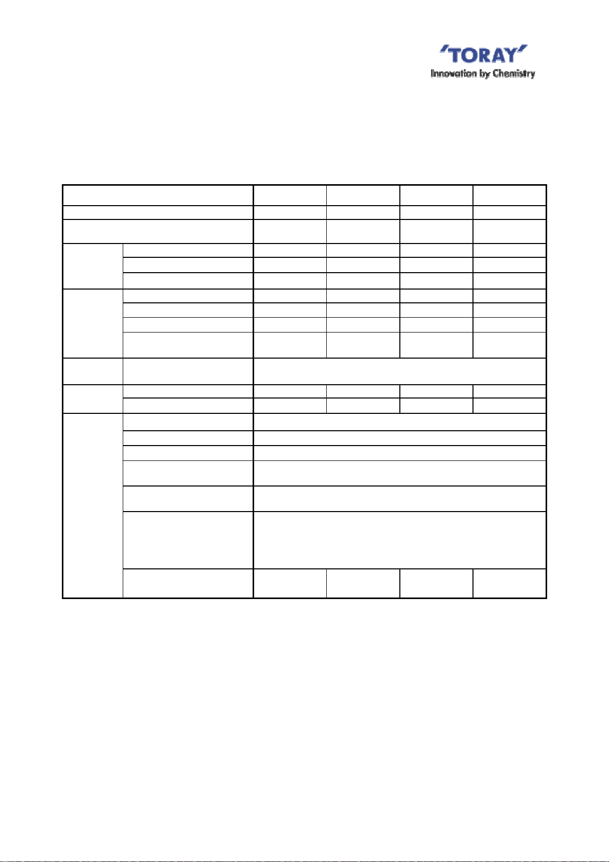
III. SPECIFICATIONS AND PERFORMANCE OF “TMR140 SERIES”
1. Specifications of Element
TableIII-1 and Fig.III-1 shows the specifications and the appearance of the element for
TMR140 Series, respectively.
Table III-1 Specifications of Element (TSP-50150)
Model name TSP-50150
Membrane configuration Flat sheet
Application Filtration of activated sludge
Filtration method Suction filtration
Nominal pore diameter (µm)
Effective membrane area (m2) 1.4
Dimensions (mm)
Weight (kg)
Main material
Total width 515
Total height 1,608
Thickness 13.5
Dry 4.8
Wet (Reference) 8.0
Membrane PVDF and PET non-woven fiber
Supporting panel ABS resin
0.08
515 mm Permeated water nozzle
50 mm
1608 mm
Fig.III-1 Appearance of Element
2. Specifications of Polyurethane Permeate Tube
Table III-2 shows the specifications of Tube.
Table III-2 Specifications of Polyurethane Permeate Tube
Material TPU-ARET*1
Inside diameter / outside diameter / total length (mm) 8/11/380
*Allowable temperature limit: 60 degree C
*1 The material name due to the ISO-18064.
9
AIRE-064-1-4
3. Specifications and Performance of “TMR140 Series” Module
Table III-3 shows the specifications of “TMR140 Series” modules.
Table III-3 Specifications of Module
Model name TMR140-050S TMR140-100S TMR140-200W TMR140-200D
Number of membrane elements 50 100 200 200
Element block structure
*
Dimensions
1
Weight(kg)
Material
Connection
*3
flange
Operating
Range
*1 The total dimensions excluding the connection tube
*2 The weight assumed in the case of sludge clogging between elements.
*3 The flange dimensions are described in the drawings attached to this manual.
*4 Except when the chemical cleaning with the designated chemical agents..
*5 The air supply equipments such as blower shall be designed b ased on the standard operating conditions
Width (mm) 810 810 840 810
Length (mm) 950 1,620 3,260 1,620
Height (mm) 2,100 2,100 2,100 4,160
Module (dry) 400 695 1,430 1,365
Aeration block (dry) 40 65 150 65
Element block (dry) 360 630 1,280 1,300
Element block
(sludge clogging)
Diffuser, Flame, Permeated
water manifold
Manifold ANSI 1 1/2inch ANSI 2inch ANSI 3inch ANSI 2inch
Air diffuser ANSI 1 1/4inch ANSI 1 1/2inch ANSI 2inch ANSI 1 1/2inch
Temperature (degree C) 5-40
pH*4 of liquid 5-10
MLSS (mg/L) Not higher than 18,000
Trans-membrane pressure
(kPa )
Cleaning chemicals feed
pressure (kPa )
Cleaning chemicals and
chemicals concentration
Scouring Air Flow rate *5
(NL/min/Module)
shown in Table VII-1.
*2
1 EBL 1 EBL 2 EBL jointed
690 1,240 2,480 2,500
304 stainless steel
(316SS or 316LSS is available as option)
Not higher than 20
Not higher than 10
Sodium hypochlorite (effective chlorine concentration)
: 2,000-6,000 mg/L(pH is around 12)
Oxalic acid : 0.5-1.0wt%
Citric acid : 1.0-3.0wt%
500 - 1,000 1,000 - 2,000 2,000 - 4,000 1,300 - 2,000
Double Deck
with 2 EBL
10
AIRE-064-1-4
Table III-4 shows the performance of ”TMR140 Series” modules.
Table III-4 “TMR140 Series” Module Performance
Model name TMR140-050S TMR140-100S TMR140-200W TMR140-200D
Permeate
water
quality
Filtration
capacity
TSS (mg/L)
*1
Turbidity (NTU)
<Reference>
*4
Quantity of water treated
3
/d)
(m
*1 This value can be attained when operated under the standard operating conditions as specified in this
Instruction Manual during a period specified separately by Toray.
*2 Measuring method of TSS is complied with Standard Method of Exami nation of Water and Wastewater
th
20
Edition (1998), Section 2540D, Total Suspended Solids Dried at 103-105 degree C or ISO 11923.
*3 Measuring method of NTU is complied with Standard Meth od of Examination of Water a nd Wastewater
th
20
Edition (1998), Section 2130, Turbidity or ISO 7027.
*4 Reference value, not guaranteed, in the case of the treatment of sewage at higher than 15 degree C of
the temperature.
*2
Not higher than 3.0
*3
Not higher than 1.0
53 105 210 210
11
AIRE-064-1-4
IV. MEMBRANE FILTRATION PROCESS DESIGN FOR “TMR140 Series”
The standard filtration pattern time chart, the schematic flow diagram of the membrane
filtration, the layout of “TMR140 Series” modules in the membrane submerged tank, and the
piping procedures are described in this section. These would help you design the membrane
filtration process with “TMR140 Series”.
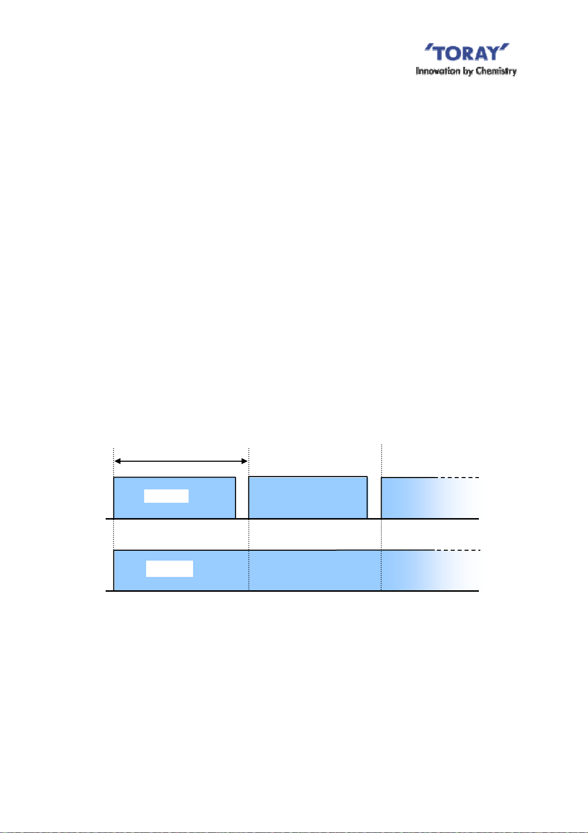
1. Standard Time Chart
Two kinds of the filtration patterns are available with "TMR140 Series". One is the simple
continuous filtration. And the other is the filtration with relaxation, that is the intermittent
filtration.
In the case of the intermittent filtration, the filtration is suspended for a short period at certain
intervals while the scouring air continues, as shown in Fig.IV-1. While the filtration is
suspended, the membrane surface is cleaned up more effectively with the scouring air due to
the absence of suction. Although the automatic system control for periodical start and stop of
the filtration is required, the intermittent filtration would be recommended if you need higher
filtration flux. The recommended time cycle for the intermittent filtration is 9-minute filtration
and 1-minute suspension
Cycle of 10 minutes
Filtration
Filtration
Suspension
9 min.
1 min.
Air diffusion
Contenuous
Fig.IV-1 Recommended Time Chart for Intermittent Filtration
2. Flow Diagram of Membrane Filtration
Two schematic flow diagrams of the membrane filtration process are shown below. One is for
the filtration with natural water head and the other is with suction pump. And some
explanation is added for the devices used in the membrane filtration process in the latter part
12
AIRE-064-1-4
 Loading...