

TopXGun T1 User Manual

©2016 TopXGun All Rights Reserved.
1
T1 User Manual V1.4
2016.07.20 Revision
For Firmware Version V3.30 or above
& Adjusting-parameter software Version V1.40 or above
Please strictly follow these steps to mount and use this product, as well as to install adjusting-parameter software
on your computer or phone.
Thank you for purchasing TopXGun product. There are web pages of T1 at our website www.topxgun.com, which is
updated regularly. You can obtain product information, technical updates and manual corrections. TopXGun
recommends you to download and use the newest user manual. The information contained in this manual is
subject to change without notice.
This manual is only for basic assembly and configuration; you can obtain more details and advanced instructions
when using adjusting-parameter software, if you find the information on software and user manual are not
consistent, adjusting-parameter software shall prevail.

©2016 TopXGun All Rights Reserved.
2
Index
INTRODUCTION ............................................................................................................................................................ 4
PRODUCT INTRODUCTION ........................................................................................................................................................ 4
IN THE BOX........................................................................................................................................................................... 4
SYMBOL DESCRIPTION ............................................................................................................................................................ 4
1 INSTALLATION & TEST ........................................................................................................................................... 5
1.1 HARDWARE INSTALLATION ........................................................................................................................................... 5
1.2 INSTALLATION AND TEST FOR ADJUSTING-PARAMETER SOFTWARE ........................................................................................ 7
1.3 UNLOCK AND LOCK .................................................................................................................................................. 12
1.4 ESC AND COMPASS CALIBRATION ................................................................................................................................ 13
1.5 HORIZONTAL CALIBRATION ........................................................................................................................................ 14
2 FLY TEST INSTRUCTIONS ....................................................................................................................................... 15
2.1 FLIGHT MODE AND CORRESPONDING RESPONDING ......................................................................................................... 15
2.2 LED INDICATOR DESCRIPTIONS ................................................................................................................................... 15
2.3 FIRMWARE UPDATE ................................................................................................................................................. 17
2.4 FIRST TEST FLIGHT.................................................................................................................................................... 20
3 ADVANCED FUNCTIONS ....................................................................................................................................... 22
3.1 ONE-KEY GO HOME ................................................................................................................................................ 22
3.2 INTELLIGENT DIRECTION ............................................................................................................................................ 22
3.3 FAIL SAFE AND GO HOME ......................................................................................................................................... 22
3.4 LOW VOLTAGE PROTECTION ...................................................................................................................................... 22

©2016 TopXGun All Rights Reserved.
3
Introduction
Disclaimer & Warning
Please read this disclaimer carefully before using the product. By using this product, you hereby agree to
this disclaimer and signify that you have read them fully.
THIS PRODUCT IS NOT SUITABLE FOR PEOPLE UNDER THE AGE OF 18.
This product is an autopilot system designed for serious multi-rotor aircraft. It can provider user with
fabulous flight experience when the system is powered normally and the connection is correct. When
setting parameters or updating firmware, we strongly recommend users to remove all propellers, and
make sure all connections are good. Keep the aircraft away from people, dangerous objects and fragile
objects. TopXGun accepts no liability for damage or injuries incurred directly or indirectly from the use of
this product in the following conditions:
1. Failure to follow the guidance of the manual to assemble or operate.
2. Damage or injuries incurred when users are drunk, taking drugs, fatigue and any other conditions no
matter physically or mentally that could impair your ability.
3. Damage or injuries caused by subjective intentional operations.
4. Malfunctions caused by refit or replacement with non-TopXGun accessories and parts.
5. Damage or injuries caused by mis-operation or subjective mis-judgment.
6. Damage or injuries caused by mechanical failures due to erosion, aging.
7. Damage or injuries caused by knowingly flying the aircraft in abnormal condition.
8. Damage or injuries caused by using in bad weather, such as typhoon, hail, fog etc.
9. Damage or injuries cause by flying in the following situations such as the aircraft in magnetic
interference area, radio interference area, government regulated no-fly zones.
10. Damage or injuries caused by operating aircraft in condition of low visibility or blocked eyesight.
11. Damage or injuries caused by infringement such as any data, audio or video material recorded by the
use of aircraft.
12. Other losses that are not covered by the scope of TopXGun liability.
Trademark
TopXGun and T1 are registered trademarks of Shanghai TopXGun robotics Co., Ltd. Names of product,
brand, etc., appearing in this manual are trademarks or registered trademarks of their respective owner
companies. This product and manual are copyrighted by TopXGun with all rights reserved. No part of this
product or manual shall be reproduced in any form without the prior written consent or authorization of
TopXGun. No patent liability is assumed with respect to the use of the product or information contained
herein.
Certifications
This product is approved with quality standards such as FCC, CE and RoHS.
©2016 TopXGun All Rights Reserved.
4
Introduction
Product introduction
TopXGun T1 can be installed on a variety of models from quad-rotor to octo-rotor, it has the
characteristics as follows:
Support 9 types of multi-rotor platform
Two basic control modes: Attitude Mode and GPS Mode
Support One-Key Go Home,Fail safe and Go Home,Low Voltage Protection
Designed with built-in vibration absorption, no extra mount frame or vibration absorption pad is required
Support S.Bus receiver, PPM receiver and PWM receiver
Support up to 128 waypoints(it needs to buy one set of wireless digital radio separately)
Support external IMU(it needs to buy separately)
Support another GPS module(it needs to buy separately)
In the Box
Warranty card×1, Main controller×1,PMU×1, GPS/Compass×1, LIU×1, OSD×1, GPS Bracket×1, Servo Cable×8,
Micro-USB×1, AV cable×1, 3M Adhesive Tape.
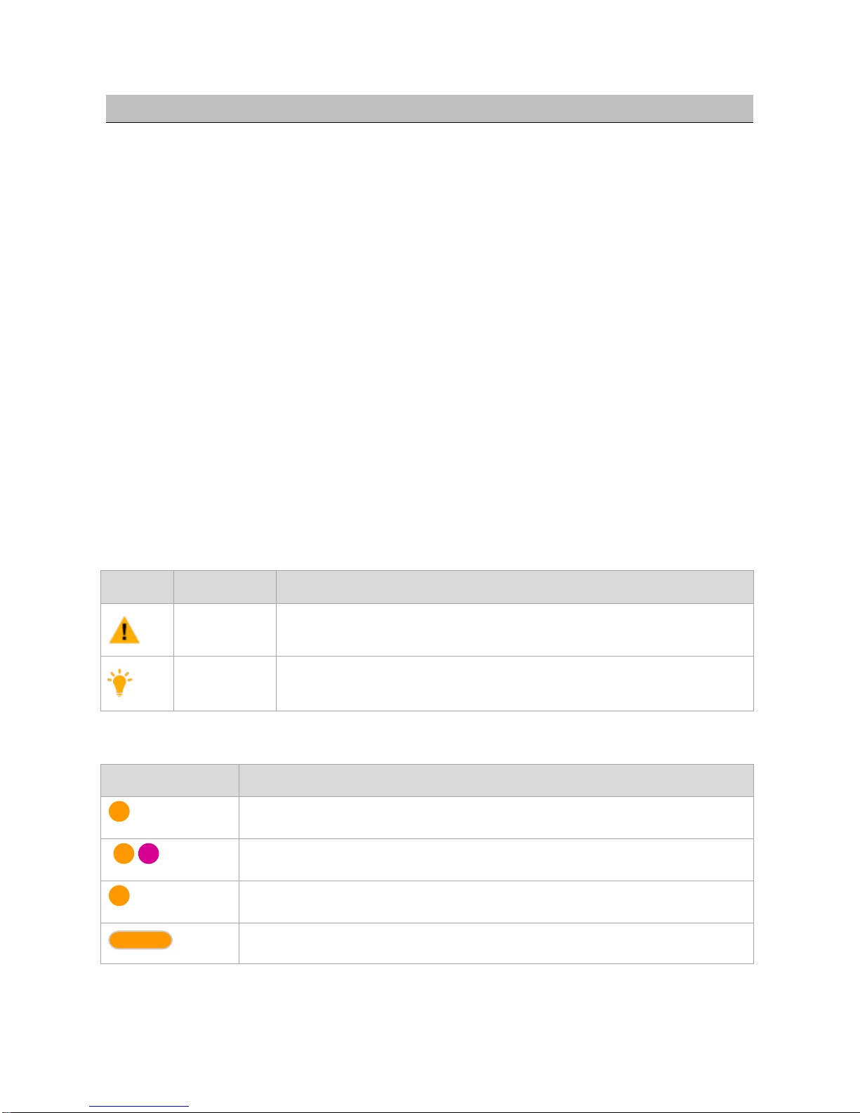
Symbol Description
Universal symbol
Symbol
Significance
Description
Attention
This mark represents potential risk, if ignore it, may result in equipment
damage, loss of data or other unpredictable consequences.
Instruction
Starting with this mark is the additional information of the body , the
emphasis and supplement on the body.
LED Symbol
Symbol
Description
(N)
It means yellow LED indicator flashes N times;
{ }(N)
It means yellow and purple LED indicator flash N times;
(∞)
It means yellow LED indicator continuously flashes;
(N)
It means yellow LED indicator is continuously on for N seconds.
©2016 TopXGun All Rights Reserved.
5
1 Installation & Test
1.1 Hardware installation
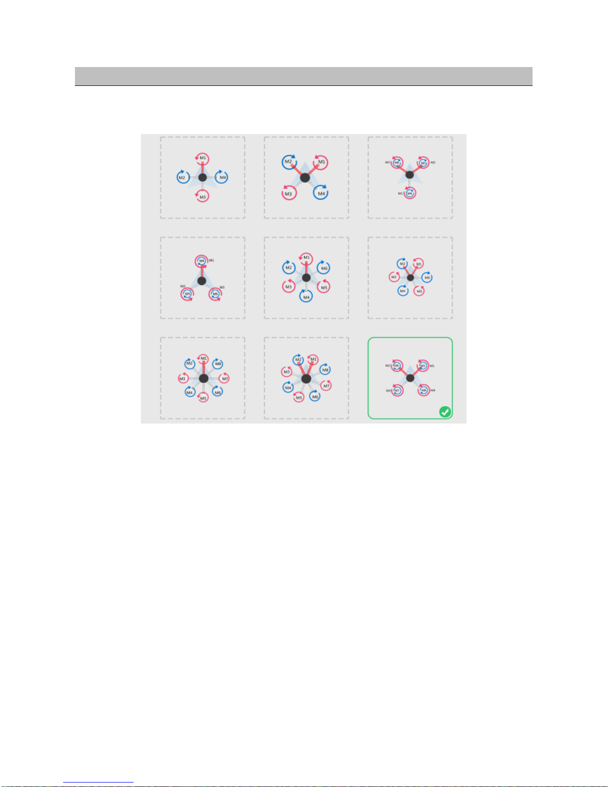
Step1. Confirm multi-rotor type, forward direction and rotation direction of the motor/propeller.
Figure 1-1 Confirm multi-rotor type
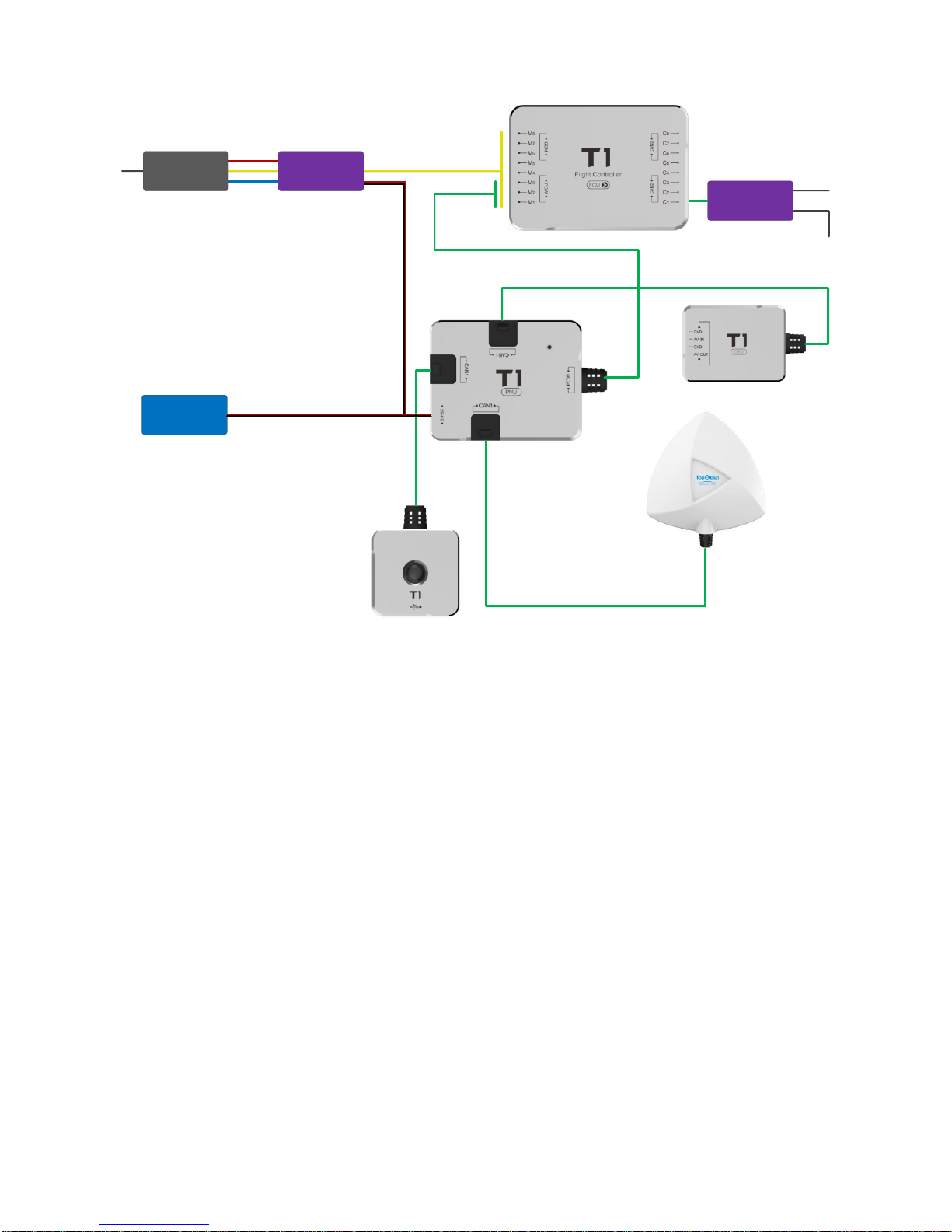
Step2. Install the controller unit, connect every part.
©2016 TopXGun All Rights Reserved.
6
0
Receiver
Battery
Motors ESC
Figure 1-2 Connection diagram of the main controller
Installation specification
FCU installation
The TopXGun logo should be facing the sky, with the orientation arrow pointing directly to the nose
direction, please mount it on a central place in board center of aircraft.
port connection
Connection of ESC: Connect M1~M8 to ESC, T1 supports up to eight motors at most (ESC signal
wire is down and earth wire is up )
Connection of receiver: S.Bus and PPM receiver can be connected directly to C1. PWM receiver
should be connected to C1~C8 on flight controller. The receiver should have at least six
channels for realizing built-in advanced functions of flight controller.(Recommended to use servo
cable of flight controller included to connect flight controller and the receiver.)
If you have matched DTU (data transmission unit), please connect it to COM port on MC, it is
recommended that you completed fixation after wiring.
PMU module installation
Please do not mount it on any other electronic device, choose a ventilated place for cooling. Make sure
the three CAN ports are convenient for connecting during installation.
©2016 TopXGun All Rights Reserved.
7
Three ports of PMU module have same definition
GPS/COMPASS module installation
GPS/COMPASS module has a built-in GPS and compass, the compass is sensitive to magnetic
interference, should be far away from electronic devices, such as motor, ESC, battery and so on. The top
side should be facing up, with the orientation arrow pointing directly to the nose direction, mount it on the
bracket horizontally. Connect it to any one of the CAN ports of PMU. It is recommended to use bracket
included in package, otherwise, please make sure it is nonmagnetic.
The module built-in magnetic compass as magnetic sensitive equipment,please pay attention
to keep it away from the motor, ESC, power battery and etc when install and use.
LIU module installation
Mount in a good place to make sure the LIU is visible during flying, connect it to any one of the CAN ports
of PMU with the enclosed 3M adhesive tape.
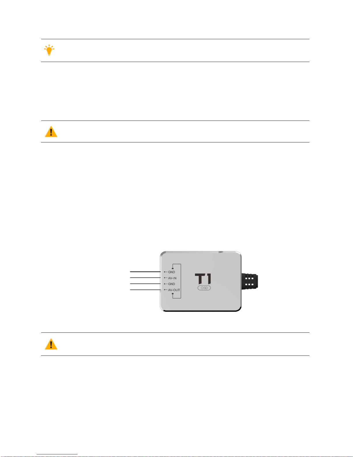
OSD module installation
Installation position requirements
Mount it on an appropriate place in board center of aircraft; make sure it‟s a ventilated place for cooling.
Connect it to any one of the CAN ports of PMU.
Port illustration
Connect AV-IN to camera’s AV,GND above AV-IN to ground electrode of camera; connect AV-OUT to AV
input port of image transmitter,GND above AV-OUT to ground electrode of image transmitter.
Video input GND
Video input signal
Video output GND
Video output signal
Figure 1-3 OSD installation
When using the module, no power can be supplied to the steering gear/worm through the
receiver, otherwise the data of OSD may lost.
1.2 Installation and test for adjusting-parameter software
Preparation before installation and configuration
T1 flight controller supports PC, Mobile phone to adjust parameters
If you do the configuration on phone, you only have to install phone app and buy bluetooth module, no
need to install any driver.
 Loading...