

Topworx Valvetop DXP, Valvetop DXS, Valvetop DXP- Flameproof Ex d IIC, Valvetop DXR Installation, Operation & Maintenance Manual
Valvetop D-Series
TM
TM
with 4-20mA Transmitter & HART Protocol
Installation, Operation & Maintenance Manual
Table of Contents
2 Switchbox Orientation
3 Mounting
3 Storage Conditions
4 DXP Dimensional Drawing
5 DXP - IIC Dimensional Drawing
6 DXS Dimensional Drawing
7 DXR Dimensional Drawing
8 Shaft Detail
9 Features & Specs
10 Installation
11 Calibration & Operation
12 Calibration & Operation
13 Maintenance
14 Pneumatic Hookup
15 Spool Valves & Pilots
16 Safe Use
17 Certifications & Approvals
18 Warranty
19 Notes
D-Series with HART Protocol Installation, Operation & Maintenance 502.969.8000
Installation on Actuator
Orientations, Normal and Reverse Acting
Normal acting is full CW when the process valve is closed and CCW when the process valve is open. Reverse acting
is full CW when the process valve is open and CCW when the process valve is closed.
90° indicator dome assemblies are design to accommodate any mounting arrangement and can be adjusted up to
9° off axis if needed. 45° indicator dome assemblies can only accommodate normal acting applications that are
mounted parallel ±9°. Consult your local distributor or factory representative for 45° reverse acting or mounted
perpendicular applications.
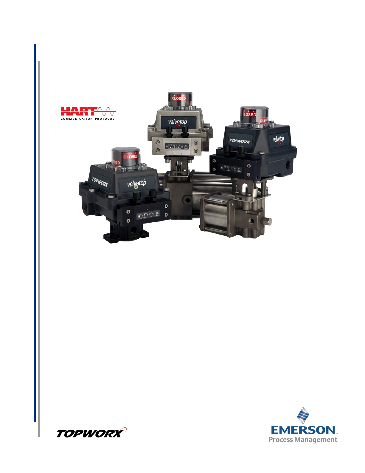
Illustration #1
The image to the left shows a Valvetop unit mounted
parallel to the process valve in the closed position.
The green arrow at the top shows the “normal acting”
direction of travel to open the valve. This is the standard
orientation and your unit unless otherwise specified will
be factory set to operate in this fashion.
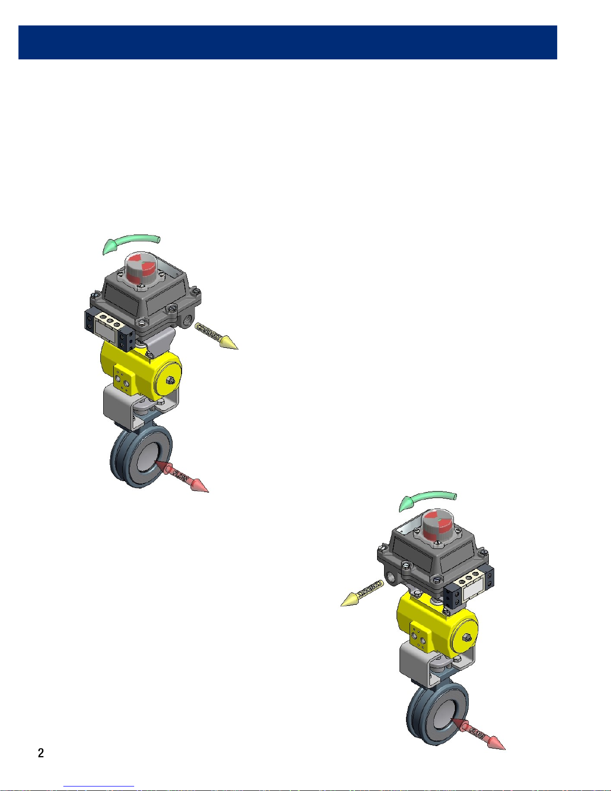
Illustration #2
The image to the right shows a Valvetop mounted
perpendicular to the process valve in the closed
position. The green arrow at the top shows the
“normal acting” direction of travel to open the valve.
Notice that the indicator dome has been rotated 90°
compared to the unit above.

www.topworx.com
Installation on Actuator (continued)
Mounting
TopWorx has numerous mounting bracket kits available to meet your specific application, whether rotary or linear.
Consult your local distributor or factory representative for ordering information. The illustration shows a direct Namur
mount on a quarter turn valve. Refer to your mounting kit documentation for specific mounting instructions.
Storage
Until conduit, conduit plugs, and any applicable spool valve port connections are properly installed, the ValveTop unit
will not support its IP/NEMA rating as the unit ships with temporary covers. Ensure that it is stored in a dry environment with a relative humidity range between 10%-95% and a temperature ranging from -40ºF (-40ºC) to 160ºF
(71ºC). Once properly installed, the temperature range listed on the nameplate will supersede this storage temperature range.
Illustration #3: Mounting Assembly
Installation Notes
1. Use caution not to allow undue axial (thrust) load on the shaft.
2. Cycle the valve a couple of times prior to final tightening of the
mounting kit hardware. This allows the shaft to self-center in the
pinion slot, or coupler. Refer to the dimensions and materials
section of this document for appropriate tightening torque.
3. Always use sound mechanical practices when torquing down
any hardware or making pneumatic connections. Refer to the
Integrated Pneumatic Control Valves section for detailed information on pneumatic connections.
4. This product comes shipped with plastic plugs in the conduit en-
tries in an effort to protect the internal components from debris
during shipment and handling. It is the responsibility of the
receiving and/or installing personnel to provide
appropriate permanent sealing devices to prevent
the intrusion of debris, or moisture, when stored
outdoors or when installed.
5. It is the responsibility of the installer, or end user, to
install this product in accordance with the National
Electrical Code (NFPA 70) or any other national or
regional code defining proper practices.

D-Series with HART Protocol Installation, Operation & Maintenance 502.969.8000
Dimensions and Materials: Valvetop DXP
MATERIALS OF CONSTRUCTION
Cast A360 aluminum with dichro-
Enclosure
Fasteners
Shaft
Shaft
Bushing
Indicator
Dome
Seals
Maximum Fastener Torque Specifications
Enclosure Housing Bolts
Indicator Dome Screws
Bottom Mounting Holes
mate conversion coating inside &
out, epoxy coated exterior rated for
250 hrs salt spray per ASTM B117
304 Stainless Steel standard
316 Stainless Steel optional
304 Stainless Steel standard
316 Stainless Steel optional
Oilite Bronze
Polycarbonate, UV F1 rated
O-ring seals available in: Buna,
Silicone, EPDM & Viton
8 ft-lbs [10.8 N·m]
320 in-oz [2.3 N·m]
10 ft-lbs [13.6 N·m]

www.topworx.com
Dimensions and Materials: Valvetop DXP - Flameproof Ex d IIC
MATERIALS OF CONSTRUCTION
Cast A360 aluminum with dichro-
Enclosure
mate conversion coating inside &
out, epoxy coated exterior rated for
250 hrs salt spray per ASTM B117
Fasteners
Shaft
Shaft Bushing
Indicator Dome
Seals
304 Stainless Steel standard
316 Stainless Steel optional
304 Stainless Steel standard
316 Stainless Steel optional
Oilite Bronze
Polycarbonate, UV F1 rated
O-ring seals available in: Buna,
Silicone, EPDM & Viton
Maximum Fastener Torque Specifications
Enclosure Housing Bolts
Indicator Dome Screws
Bottom Mounting Holes
8 ft-lbs [10.8 N·m]
320 in-oz [2.3 N·m]
10 ft-lbs [13.6 N·m]

D-Series with HART Protocol Installation, Operation & Maintenance 502.969.8000
Dimensions and Materials: Valvetop DXS
MATERIALS OF CONSTRUCTION
Enclosure
Fasteners
Shaft
Shaft Bushing
Indicator Dome
Seals
Cast 316 Stainless Steel
304 Stainless Steel standard
316 Stainless Steel optional
304 Stainless Steel standard
316 Stainless Steel optional
N/A
Polycarbonate, UV F1 rated
O-ring seals available in: Buna,
Silicone, EPDM & Viton
Maximum Fastener Torque Specifications
Enclosure Housing Bolts
Indicator Dome Screws
Bottom Mounting Holes
8 ft-lbs [10.8 N·m]
320 in-oz [2.3 N·m]
10 ft-lbs [13.6 N·m]
 Loading...