

Page 1
Installation, Operation & Maintenance Manual
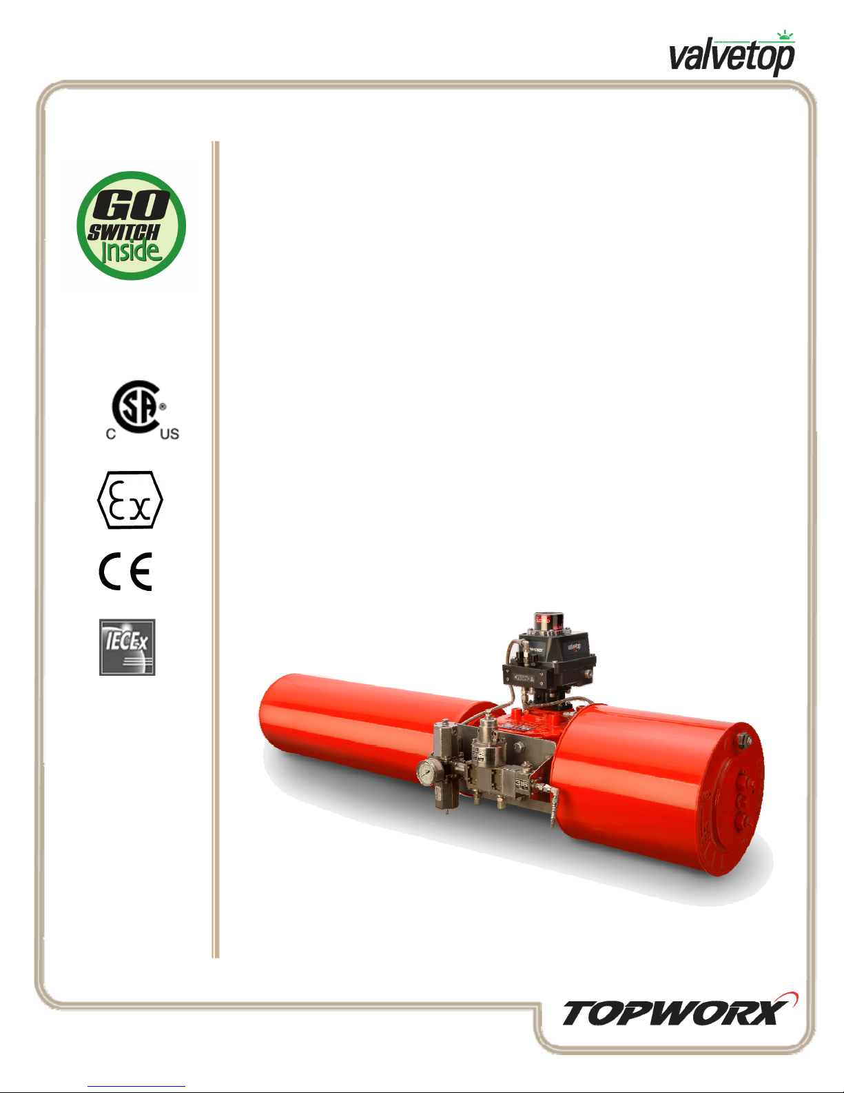
DXR with GO Switches
The DXR combines position sensors, internal mount pilot device and an
on-board spool valve into a single enclosure.
■ Intrinsically Safe Class I, Div. 1 & 2, Groups A, B, C, D; Class II, Div. 1 & 2,
Groups F, G (Ex ia IIC, II 1 GD)
■ Flameproof/Explosion-proof Class I, Div. 2, Groups A, B, C, D; Class II,
Div. 2, Groups F, G (Ex e IIC T4, II 2 GD) (Ex em IIC T4, II 2 GD)
■ General Purpose, Type 4, 4X
■ SPDT Contact Switches
■ Integral Solenoid Pilot Valve (24VDC, 110Vac, and Intrinsically Safe)
0518
Table of Contents
2 Outline Dimensions
2 Indicator Assembly
3 DXP Enclosure Assembly
4 Spool Valve Specifications
5 Spool Valve Assembly
5 Pilot Device Assembly
6 GO Switch Assembly
7 Shaft / Cam Assembly
7 Approvals & Warranty
3300 Fern Valley Road, Louisville, Kentucky 40213 USA www.topworx.com
502.969.8000 phone 502.969.5911 fax [email protected]
Page 2
DXR-GO Switch Installation, Operation & Maintenance
S
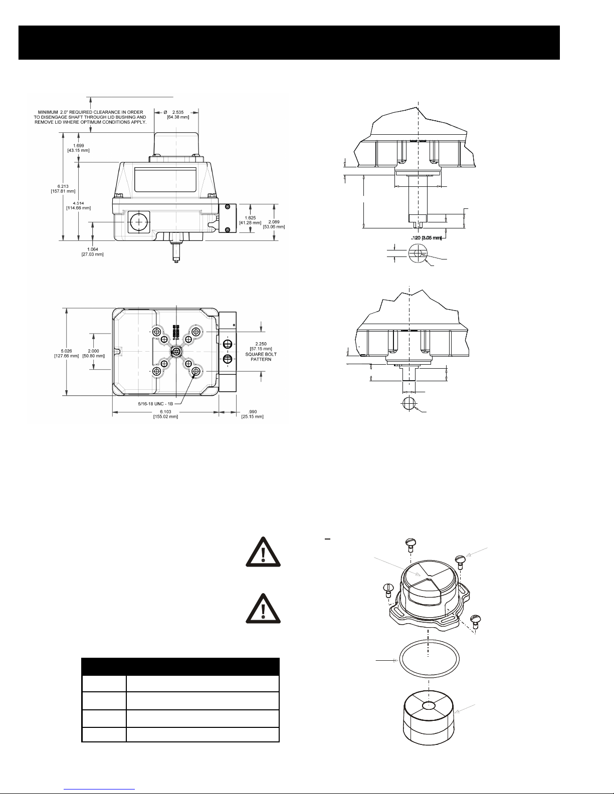
Illustration #1 : Outline Dimensions
.164 [4.17 mm]
1.076 [27.33 mm ]
NAMUR SHAFT
Ø.938 [23.83 mm]
Ø
Ø.375[9.53mm]1.56 [3.96mm]
502.969.8000
.285 [7.24 mm]
.175[4.45mm]
Installation Notes
1. Be cautious not to allow undue axial (thrust) load on the shaft.
2. Cycle the valve a couple of times prior to final tightening of the mounting
kit hardware. This allows the shaft to self-center in the pinion slot, or coupler.
3. Always use sound mechanical practices when torquing down any hardware
or making pneumatic connections.
4. This product comes shipped with plastic plugs in the conduit
entries in an effort to protect the internal components from debris
during shipment and handling. It is the responsibility of the
receiving and/or installing personnel to provide appropriate
permanent sealing devices to prevent the intrusion of debris,
or moisture, when stored outdoors or when installed.
5. It is the responsibility of the installer, or end user, to install
this product in accordance with the National Electrical Code
(NFPA 70) or any other national or regional code defining
proper practices.
Q.
.164 [4.17 mm]
.335 [8.51 mm]
STANDARD SHAFT
.250 [6.35 mm]
.249 [6.32 mm]
Ø.375 [9.52 mm ]
Illustration #2 : Indicator Assembly
Indicator Dome,
O
+
5 adjustable
Polycarbonate
with keyed mask.
Several rotation and
form options.
10-32 Captive screws,
Stainless (x4)
Indicator / Dome Replacement Kits
AV-GB002 90º, Green/Open, Red/Closed, Buna O-Ring
AV-YB002 90º, Yellow/Open, Black/Closed, Buna O-Ring
AV-TB002 90º, Green/Thru, Red/Divert, Buna O-Ring
AV-4B002 90º, Green/Open, Red/Closed, Buna O-Ring
2
Available in Buna-N,
O-ring
Silicone, EPDM, Viton
Color-coded Indicator is
available in several
coordinating rotations and
forms for various valve
types, such as 90 , 180
00
and Thru-divert applications.
Page 3
www.topworx.com
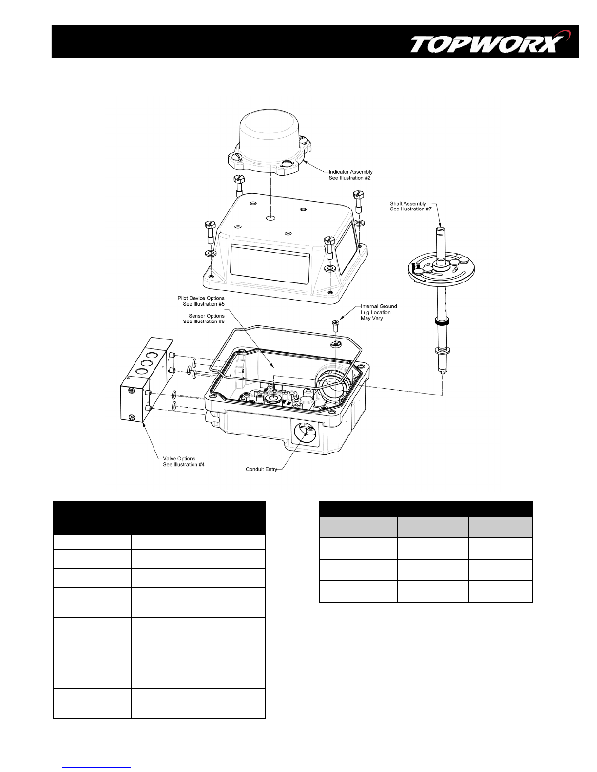
Illustration #3 : DXR Enclosure Assembly
Enclosure Specifications/Materials
of Construction
®
Enclosure
Fasteners
Shaft Bushings
Shaft
O-Ring Seals Buna-N, Silicone, EPDM, & Viton
Conduit Entries
Mounting Holes
Valox
304 Stainless Steel housing bolts
PH15-7 Stainless Steel C-Clip
®
Delrin
304 Stainless Steel
(2) 1/2" NPT resin
(2) 3/4" NPT resin
(2) 1/2" NPT 316 Stainless Steel
(2) 3/4" NPT 316 Stainless Steel
(2) M20 resin
(2) M25 resin
(4) M20 2X 316 Stainless Steel, 2X resin
(4X) 5/16-18 UNC tapped holes on
2.25” (57.15 mm) Square Pattern,
Optional F05 Pattern
Max Torque Values for Fasteners
Description Max Torque
Enclosure Lid
Screws
Indicator Dome
Screws
Bottom Mounting
Holes
®
Torque
See Spec
Table
10-32 UNF
5/16-18 UNF
Value
10 in. lbs.
320 in. oz.
8 ft. lbs.
3
Page 4
DXR-GO Switch Installation, Operation & Maintenance
Pneumatic Hookup Procedures
Prior to connecting the supply air to the spool valve, flush the system to
remove any debris or contaminates. Galvanized pipe can easily flake and
contaminate the system and therefore is not recommended. A 40 micron
point of use filter at every device is recommended.
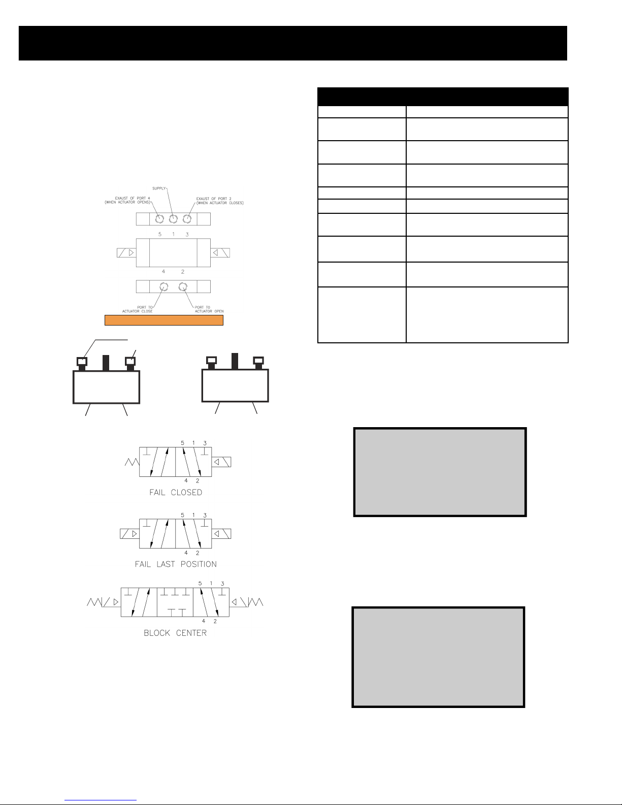
4-Way Spool Valves
The TopWorx spool valve is a 5 port, 4-way valve driven by an internally
mounted pilot valve. The spool valve supply port and work ports are marked
as follows:
DOUBLE ACTING ACTUATORS SPRING RETURN ACTUATORS
***NEVER PLUG, OR BLOCK, PORT 5***
Always install vents
Supply
5
1
4
or speed controls
3
2
Port to OpenPort to Close
5
Plug
4
Supply
1
3
2
Port to Open
Highly Recommended
TopWorx highly recommends Locktite 567 brand thread sealant. Do not use
a hard setting pipe compound. If Teflon thread seal tape is used, start the
wrap on the second thread from the leading thread of the fitting. This will
prevent tape shreds from contaminating the spool valve seals.
Flow controls (AL-M21) or Breathers (AL-M31) should be installed in the
exhaust ports to keep debris from falling into the spool valve and damaging
the seals. This must be addressed prior to installation, or storage.
4
Medium
Max Operating
Pressure
Min. Operating
Pressure
Ambient
Temperature Range
Flow Coefficient
Environment Rating
Port Size
Manual Override
Valve Body
Valve Seals
Spool Valve Specifications
Dried, filtered air (40 micron)
100psi (0.7 MPa) (6.89Bar)
30psi (0.28 MPa) (2.76Bar)
Refer to Product Nameplate Marking
1.2Cv or 3.0Cv (1.0 for ColdTemp™)
Type 4, 4X, IP67
1/2” NPT for 3.0Cv valve
1/4" NPT for 1.2Cv valve
Available in Latching/Non-Latching Push
Type & Palm Actuator Type
Available in Hardcoat Anodized
Aluminum, 304, or 316 Stainless Steel
Spool Seals: Buna-N
Valve Body Seals available in
Buna-N, Silicone, EPDM & Viton.
ColdTemp™ Spools are lap-joint
technology containing no seals.
Don’t forget!
TopWorx has a complete line of breathers,
flow controls, regulators and filters.
Check out www.topworx.com or call us at
502.969.8000 for more details
DID YOU KNOW?
TopWorx manufactures the globally-known
GO Switch Leverless Limit Switch, which
comprises a full line of harsh environment
sensors. If your application is very cold, very
hot, under water or in a caustic atmosphere,
then GO Switch has the answer.
502.969.8000
Page 5
www.topworx.com
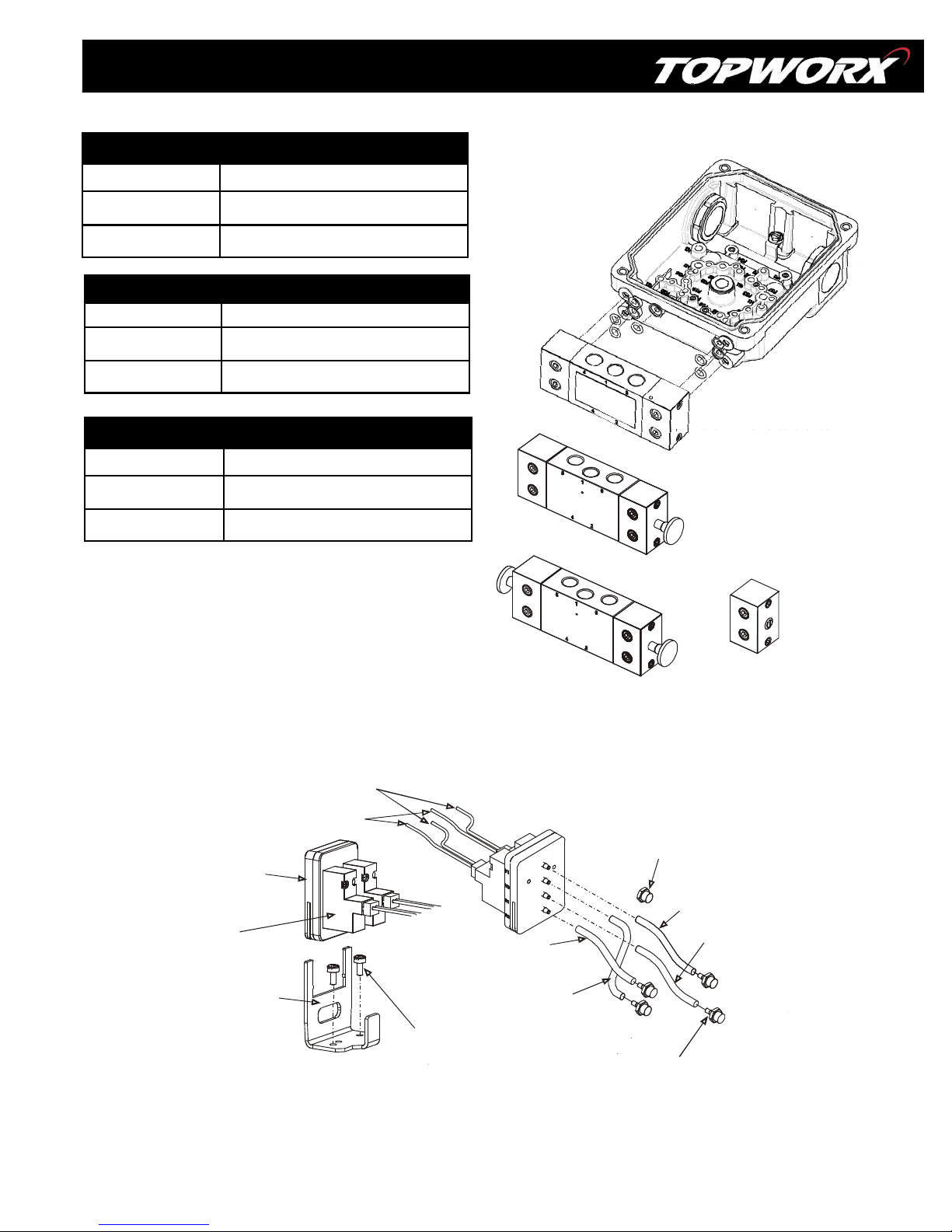
Spool Valve with No Manual Override
+
Fail Closed Spool Valve Replacement Assemblies
AV-BFCVA20 Std Alum Spool Valve Assy w/Buna seals
AV-BFCVS20 Std 304SS Spool Valve Assy w/Buna seals
AV-BFCV620 Std 316SS Spool Valve Assy w/Buna seals
Fail Last Position Spool Valve Replacement Assemblies
AV-BFLPVA20 Std Alum Spool Valve Assy w/Buna seals
AV-BFLPVS20 Std 304SS Spool Valve Assy w/Buna seals
AV-BFLPV620 Std 316SS Spool Valve Assy w/Buna seals
Block-Center Spool Valve Replacement Assemblies
AV-BBCVA20 Std Alum Spool Valve Assy w/Buna seals
AV-BBCVS20 Std 304SS Spool Valve Assy w/Buna seals
Illustration #4 : Spool Valve Assembly
AV-BBCV620 Std 316SS Spool Valve Assy w/Buna seals
Consult factory for more options.
Illustration #5 : Pilot Device Assembly
Red
Black -
Manifold
24V, 110V, 220V or
IntrinsicallySafe Pilot Device
(no plug connector on I.S. pilots)
(x1) for Fail Closed Apps
(x2) for Fail Last Position &
Block Center Apps
RED Urethane
Tubing (Supply)
Spool Valve with Single Palm Actuator Override
Push-button Style Override
Spool Valve with Dual Palm Actuator Override
10-32 Nylon Plug
Used in Fail Closed
Applications
YELLOW Urethane
Tubing (Work)
RED Urethane
Tubing (Supply)
Bracket
YELLOW Urethane
Tubing (Work)
4-40x0.25 (x2)
10-32 Barb Fitting
(x4)
5
Page 6
DXR-GO Switch Installation, Operation & Maintenance
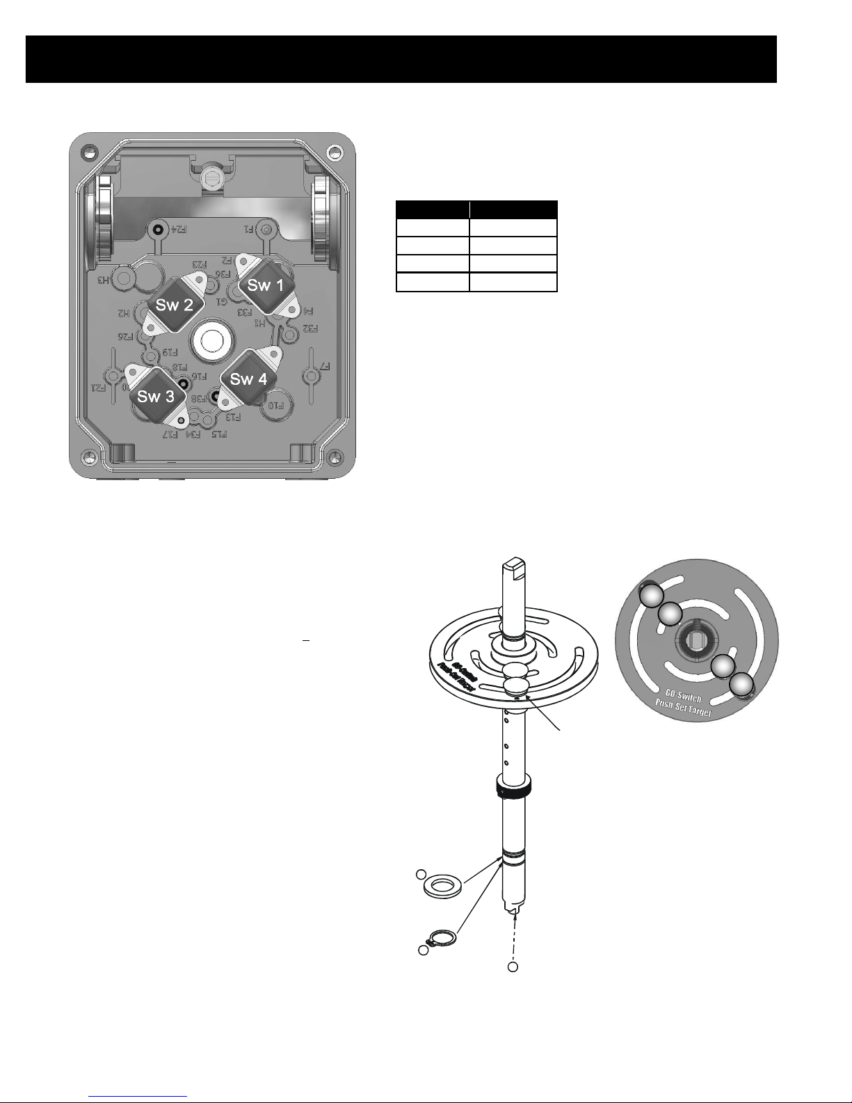
Illustration #6 : GO Switch Assembly
502.969.8000
Switch Calibration Procedure
Never perform switch calibration procedure while area is known to be
hazardous.
For Intrinsically Safe models, unit must be wired in accordance to Control
Drawing
S-K094/094A. Or, for standard explosion-proof models:
Calibration may be performed using a Volt-Ohm meter by using the Ohm setting
across COM and NO. When switch is active, the meter will read <
the Diode setting may used simply to indicate continuity.
If a 120Vac source is used, an appropriately sized resistor must be used in
series to limit current to a maximum of 15 Amperes when circuit rating is unknown, or permanent damage may occur.
Step 1: With valve in the CLOSED position. Push down and slide target magnet
#1 until SW1 activates. Release the target magnet to lock the position.
Step 2: Rotate valve to the OPEN position. Push down and slide target magnet
#3 until SW3 activates. Release the target magnet to lock the position.
Step 3: Cycle valve CLOSED and OPEN several times to insure switches will
maintain calibration.
0.5 Ohms, or
For Reverse Acting Actuators:
Step 1: Loosen the 6-32 x .25 set screw on the target disk and lift up on the
target disk enought to disengage the locator pin.
Step 2: While holding the shaft from turning, rotate the target disk 90 Degrees
counter-clockwise. Push down on the target disk until the locator pin engages.
Step 3: Tighten the set screw to 40 in/oz.
Step 4: Perform steps 1-3 above.
Note: For other valve configurations the target disk can be moved in 90 degree
increments to adapt to the application. L4 units are adjusted per application.
MODEL#
DXP-L1 SW1
DXP-L2 SW1 & SW3
DXP-L3 SW1 - SW3
DXP-L4 SW1 - SW4
35 Series GO Switch
3A/24VDC, 4A/120VAC
Hermetically Sealed
Illustration #7 : Push Set Target Assembly
2
1
SWITCHES
3
4
2
1
Each target is set by:
Push Down, Slide & Release
NOTE: If target disk is removed
for switch maintenance, align
disk slot to pin on shaft.
3
6
Page 7
www.topworx.com
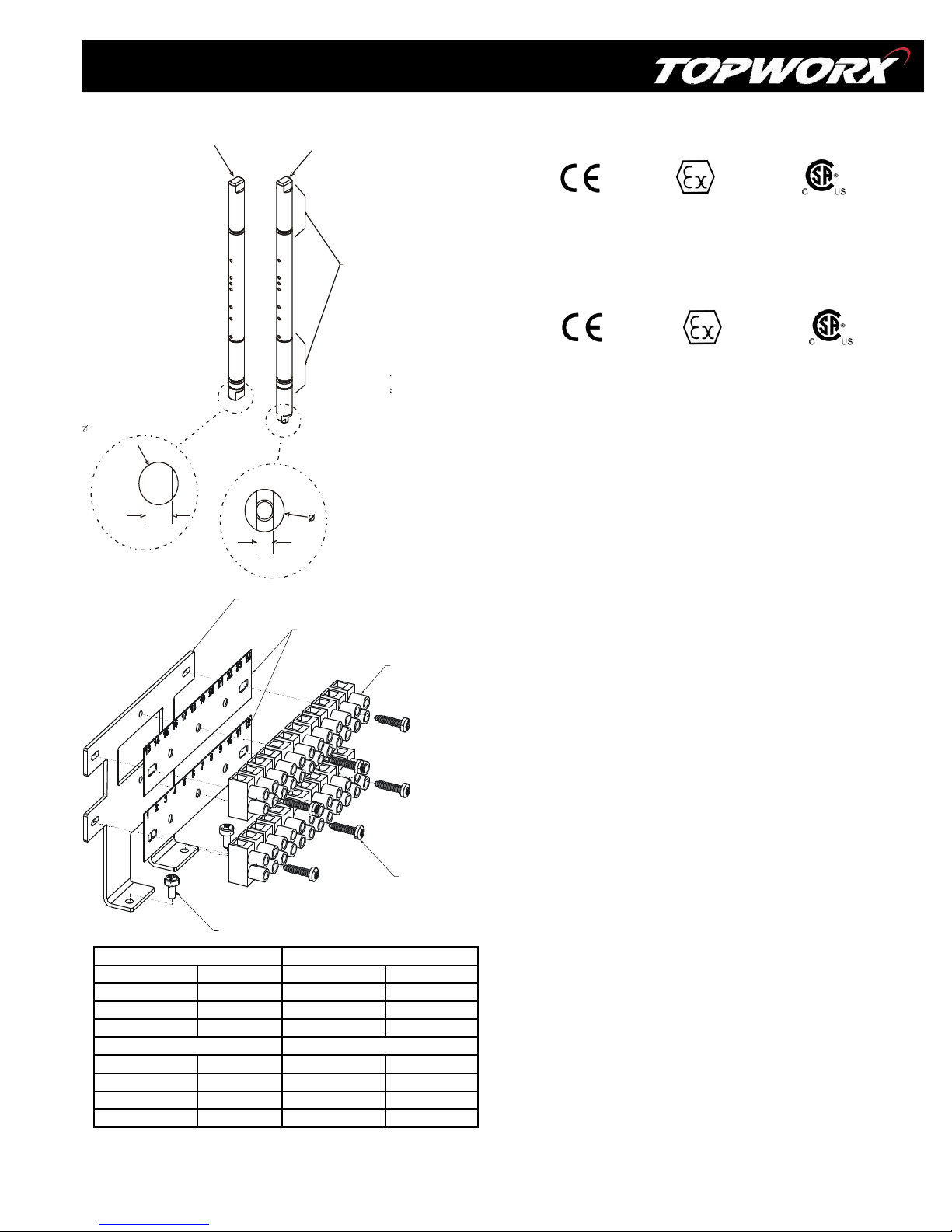
Illustration #7 : Shaft Assembly
Standard 0.25” DD Shaft,
Stainless
NAMUR Shaft,
Stainless
Telemetering Equipment for use in Hazardous Locations
Lubrication
Areas
2
0.375 [9.53mm]
0.25 in
For more shaft dimension
details, see Page 2.
Bracket
4-40x0.25 S EM sc rew (x2)
To rq ue 1 00 IN -O Z
0.375 [9.53mm]
4mm
Terminal Strip Label
12pt Terminal Strip (x2 )
4-40x0.5 self tap screw (x6)
To rq ue 40 IN -O Z
Switch 1 Switch 2
Green to GND Ground Green to GND Ground
COM (Black) Terminal 2 COM (Black) Terminal 5
NO (Blue) Terminal 3 NO (Blue) Terminal 6
NC (Red) Terminal 1 NC (Red) Terminal 4
Switch 3
Switch 4
Green to GND Ground Green to GND Ground
COM (Black) Terminal 8 COM (Black) Terminal 11
NO (Blue) Terminal 9 NO (Blue) Terminal 12
NC (Red) Terminal 7 NC (Red) Terminal 10
**The above terminations are typical and may vary depending on your configuration. Refer to the
wiring diagram located on the inside top housing for a wiring diagram specific to your configuration.
0518
II 1 GD
Zone 0 Ex ia IIC T4 -20ºC ≤ Tamb ≤ 60ºC; IP67
SIRA 08ATEXxxxxx, SIR08.xxxxx
Class I, Div. 1 & 2, Groups A, B, C, D; Class II, Div. 1 & 2, Groups F, G
Type 4, 4X
Intrinsically Safe/Securite Intrinseque
Install per Control Drawing: S-K094/094A
0518
II 2 GD
SIRA 08ATEXxxxxx, SIR08.xxxxx
Zone 1 Ex e IIC T4 -20ºC ≤ Tamb ≤ 60ºC; IP67
Zone 1 Ex em IIC T4 -20ºC ≤ Tamb ≤ 60ºC; IP67
Class 1, Div. 2, Groups A, B, C, D; Class II, Div. 2 T4, Groups F, G
Type 4, 4X
Special Conditions of Safe Use (All installations)
Clean only with a damp cloth to prevent possibility of electrostatic
discharge.
For Explosion Proof installations, the internal ground connection
shall be used and the external ground connection, if supplied in
addition, is supplemental bonding allowed where local authorities
permit, or is required.
When installing with a third party listed nipple-mount solenoid, it is
the responsibility of the installer to provide fittings, and apparatus,
suitable for the area classification in accordance with the National
Electrical Code.
All cable entry devices or conduit stopping boxes shall be certified in
type of explosion protection ‘d’, suitable for the conditions of use
and correctly installed.
Warranty
TopWorx warrants that each item of new equipment manufactured by it will be free
from defects in material and workmanship under normal use and service; its obligation under this Warranty, being limited to making good, at its factory, and part of
parts thereof, which shall be returned to it with transportation charges prepaid, within
one year after the date of the purchase of such equipment by the original purchaser,
and which its examination shall disclose to its satisfaction to have been thus defective. TopWorx however, assumes no risk or liability for results of the use of the
products purchased from it.
THIS WARRANTY IS IN LIEU OF ALL OTHER WARRANTIES, WHETHER OF MERCHANTABILITY FITNESS, OR OTHERWISE EXPRESSED OR IMPLIED, AND ALL OTHER
OBLIGATIONS OR LIABILITIES AND TOPWORX NEITHER ASSUMES , NOR AUTHORIZES ANY PERSON TO ASSUME FOR IT ANY OTHER LIABILITY IN CONNECTION WITH
THE SALE OF THIS EQUIPMENT.
No claims for labor in replacing defective parts and equipment and consequential
damages will be allowed by the Company.
This Warranty shall not apply to equipment which has been subjected to misuse,
negligence or accident.
This Warranty shall not apply to any equipment which shall have been repaired or
altered, outside the Company's factory so as to affect such equipment's stability or
reliability in the judgement of the
7
Page 8
DXR-GO Switch Installation, Operation & Maintenance
502.969.8000
About Valvetop™
Valvetop valve networking and control devices link on/off valves to process control systems via a variety of fieldbus protocols. Valvetop valve
controllers and monitors support multiple bus protocols, operate in the most demanding plant conditions, and carry a variety of global approvals.
Whether your application is rotary or linear, fieldbus or conventional, hazardous or general purpose, we have a suitable solution for you.
For inquiries, contact TopWorx at: 502.969.8000
www.topworx.com
[email protected]
About TopWorx
TopWorx is the leader in field networking, valve control, and position sensing solutions for the process industries. Our products and services help
plants, mills, and pipelines improve their performance by making it easy to implement modern automation technologies.
TopWorx, Valvetop, Lumitech, GO Switch, and VIP are all trademarks of TopWorx, Inc.
All other marks used in this document are the property of their respective owners.
Information contained herein is subject to change without notice.
8
3300 Fern Valley Road
Louisville, Kentucky 40213 USA
502.969.8000 phone
502.969.5911 fax
www.topworx.com
©TopWorx, Inc. All rights reserved.
ES-01189-1 REV1
 Loading...