


User’s Manual for
TL-403 Laser Engraving
and Cutting Control
System
Shenzhen Topwisdom Technology Co., Ltd
Add: 4F, NO.58, East Side of Yousong Road, New Longhua District, ShenZhen, China,
518109
Tel: +86-0755-82057902
Fax: +86-0755-82057892
Website: http://www.topwisdom.com.cn

泰智科技
Shenzhen Topwisdom Technology Co., Ltd
Copyright Statement
Shenzhen Topwisdom Technology Co., Ltd.
All rights reserved.
Shenzhen Topwisdom Technology Co., Ltd. (Topwisdom Technology hereinafter)
reserves the rights of final interpretation and modification for this manual and
declaration. Topwisdom Technology owns the patents, copyright and other intellectual
property rights for its product and software. Without authorization, no one is allowed to
copy, excerpt, reproduce, process, disseminate and use this product and its relative
parts directly or indirectly.
Disclaimer
Topwisdom Technology reserves the right to modify the content described in this
manual without advance notice. Topwisdom Technology is not responsible to any direct,
indirect, or consequential damage or liability caused by improper use of this manual or
the product. Machinery in motion can be dangerous! It is the responsibility of the user
to design effective error handling and safety protection as part of the machinery.
Topwisdom Technology shall not be liable or responsible for any incidental or
consequential damages.
Technical Support
To get our technical support and after-sale service:
Tel: +86-0755-82057902
Fax: +86-0755-82057892
Website: http://www.topwisdom.com.cn

泰智科技
Shenzhen Topwisdom Technology Co., Ltd
I
Content
Part 1 Overview ............................................................................................................... 1
1.1 System Overview ............................................................................................... 1
1.2 Notes and Warning............................................................................................. 2
1.3 Work Environment .............................................................................................. 2
1.4 Power Supply and Grounding ............................................................................ 2
1.4.1 Power supply requirements ..................................................................... 2
1.4.2 Grounding requirements .......................................................................... 2
1.5 Accessory List .................................................................................................... 3
Part 2 Wiring Installation Instruction................................................................................ 5
2.1 System Wiring Diagram ..................................................................................... 5
2.2 Installation Dimension ........................................................................................ 6
2.2.1 Panel ........................................................................................................ 6
2.2.2 Mainboard ................................................................................................ 7
2.3 Wiring Instruction................................................................................................ 9
2.3.1 Interface Broad ........................................................................................ 9
2.3.2 Wiring Diagram ........................................................................................ 9
2.4 Interface Instruction .......................................................................................... 13
2.4.1 Power Signal .......................................................................................... 13
2.4.2 U-DISK Port ........................................................................................... 14
2.4.3 PC Connection Port ............................................................................... 14
2.4.4 NETWORK Port ..................................................................................... 14
2.4.5 Output ..................................................................................................... 14
2.4.6 Laser Power Interface............................................................................ 16
2.4.7 Input ....................................................................................................... 17
2.4.8 Input Signal Diagram ............................................................................. 19
Part 3 Software Installation ............................................................................................ 20

泰智科技
Shenzhen Topwisdom Technology Co., Ltd
II
3.1 Installing CoreDRAW Direct Output................................................................. 20
3.1.1 Manual Install ......................................................................................... 21
3.1.2 Auto install .............................................................................................. 22
3.2 Uninstalling CorelDRAW Direct Output ........................................................... 23
3.3 Installing CAD Direct Output ............................................................................ 23
3.4 Uninstalling CAD Direct Output ....................................................................... 25
3.5 USB Driver Installation ..................................................................................... 26
3.6 USB Port Setting .............................................................................................. 29
3.6.1 View the assigned COM Port by Computer .......................................... 29
3.6.2 Change the Assigned COM port by Computer ..................................... 32
3.7 IP Setting .......................................................................................................... 33
Part 4 Software Operation Guide .................................................................................. 37
4.1 CorelDRAW Direct Output Software Operation .............................................. 37
4.1.1 Layer Parameter Setting........................................................................ 38
4.1.2 Coordinate Setting ................................................................................. 42
4.1.3 Track Setting .......................................................................................... 43
4.1.4 Single Axis Operation ............................................................................ 44
4.1.5 Output Engrave ...................................................................................... 45
4.2 The Equipment Management .......................................................................... 49
4.2.1 Toolbar .................................................................................................... 50
4.2.2 Parameter Setting .................................................................................. 50
4.2.3 Embroidery Import ................................................................................. 55
4.2.4 Import bitmap ......................................................................................... 56
4.2.5 Curve Precision...................................................................................... 57
4.3 CAD Direct Output Software Operation ........................................................... 57
4.4 CAD Direct Output Software Supplementary Description .............................. 58
4.4.1 The Support of AutoCAD Direct Output Annotation Text ...................... 58
4.4.2 Carving Gradient Sketch Map ............................................................... 60
4.4.3 Coordinate System ................................................................................ 60

泰智科技
Shenzhen Topwisdom Technology Co., Ltd
III
4.4.4 Supplementary Description of Carving ................................................. 61
4.4.5 Supplementary Description of Software and CAD Direct Output ......... 62
Part 5 The Operation Panel ........................................................................................... 66
5.1 The Panel Operation and Buttons Function Introduction ................................ 66
5.1.1 The Panel ............................................................................................... 66
5.1.2 Buttons Function Introduction................................................................ 66
5.2 The Main Interface Introduction ....................................................................... 69
5.2.1 Power Interface ...................................................................................... 69
5.2.2 Standby Interface ................................................................................... 69
5.2.3 Speed Setting Interface ......................................................................... 71
5.2.4 Power Light Intensity Interface .............................................................. 71
5.2.5 Range Preview Interface ....................................................................... 72
5.2.6 Single Axis Movement Interface ............................................................ 73
5.2.7 File Selection Interface .......................................................................... 73
5.2.8 U disk File Interface ............................................................................... 74
5.2.9 The Main Menu Setting.......................................................................... 75
5.3 File Setting ........................................................................................................ 76
5.4 The Integrate Settings ...................................................................................... 77
5.4.1 Laser Set ................................................................................................ 77
5.4.2 Equipment Set ....................................................................................... 78
5.4.3 Axis Set .................................................................................................. 80
5.4.4 Back Set ................................................................................................. 83
5.4.5 User Set ................................................................................................. 85
5.5 System Information .......................................................................................... 87
5.5.1 The Password Setting............................................................................ 88
5.6 System Test ...................................................................................................... 89
Part 6 the Frequently Asked Question Help.................................................................. 91
6.1 Power-on Reset Question ................................................................................ 91
6.2 The Laser Light Question ................................................................................. 92

泰智科技
Shenzhen Topwisdom Technology Co., Ltd
IV
6.3 The PC Connection Question .......................................................................... 92
6.4 The Reading and Writing of U disk Question .................................................. 93

泰智科技
Shenzhen Topwisdom Technology Co., Ltd
1
Part 1 Overview
1.1 System Overview
Thank you very much for using laser engraving control system of our company!
This system can be used with various types of laser engraving cutting machine, meets
your different requirements for processing.
Use High-Performance 32-Bit CPU with Single-Precision Floating-Point Unit (FPU),
the main frequency is up to 150MH. Setting device parameter out of PC completely.
All coupler completely isolated from outside interference, the system is reliable.
Support USB2.0 port, U disk reading and writing, support U disk system upgrade;
Support network , PC-communication is more convenient, safe, and reliable.
With 64MB storage, work independently form PC, which is useful for the quantities
of engraving and cutting production.
Support 5 axises motion control(X Y Z U V, XY is for laser cutting control, Z is
feeding axis, U is lift axis, V is for the second laser cutting head).
Support double laser head cutting, support leftover cutting. Each laser power is
able to be control independently.
Support feeding, lifting, rotating engraving, metal cutting, scale cutting, automatic
blowing, automatic focusing, foot switch, cover protect, power-off cutting
restoration, system lock, device management.
S-shape acceleration and deceleration and adjustable velocity profile, meet the
demand of smooth cutting and high speed working.
Before using, please read our manual carefully, ensure to operate our system
correctly.
Please keep the manual well, and it’s convenient for your future references.
Because of different configuration, some devices have not some of the
functions listed in the manual, the details subject to appropriate operation
functions.

泰智科技
Shenzhen Topwisdom Technology Co., Ltd
2
1.2 Notes and Warning
Prohibit the non-professionals to maintenance and debug the electrical system, if
not, this will reduce device’s safety performance, and expand failure, even cause
accident and property loss.
Please do not piles up debris on the control box, and in the course of using,
regularly remove the dust of the control box surface and filters, to keep good
ventilation.
When users have to open the cover of the control box, must cut off the power after
5minutes and under the professionals’ guidance, only can be allowed to touch the
components in the electrical control box!
Prohibit touching any motion parts or opening the control equipments when the
machine is working, or it maybe bring about the accident and machine can’t work.
Prohibit using the electrical equipment in the damp, dust, corrosive gas, flammable
gas area, or it maybe cause the electrical shock or fire!
1.3 Work Environment
Ventilation, sanitation, and less dust
Storage temperature: 0-50℃
Work temperature: 5-40℃
Work relative humidity: 30%-90%(no condensation)
1.4 Power Supply and Grounding
1.4.1 Power supply requirements
Core power supply: DC 5V, 3A; External power supply: DC 5V, 3A
According to different machine configurations, power consumption is between
0.1-0.2KW
1.4.2 Grounding requirements
In order to prevent electrical equipment due to leakage, over-voltage, insulation etc
causes of the electrical shock or fire, please make the electrical control reliable
grounding.
泰智科技
Shenzhen Topwisdom Technology Co., Ltd
3
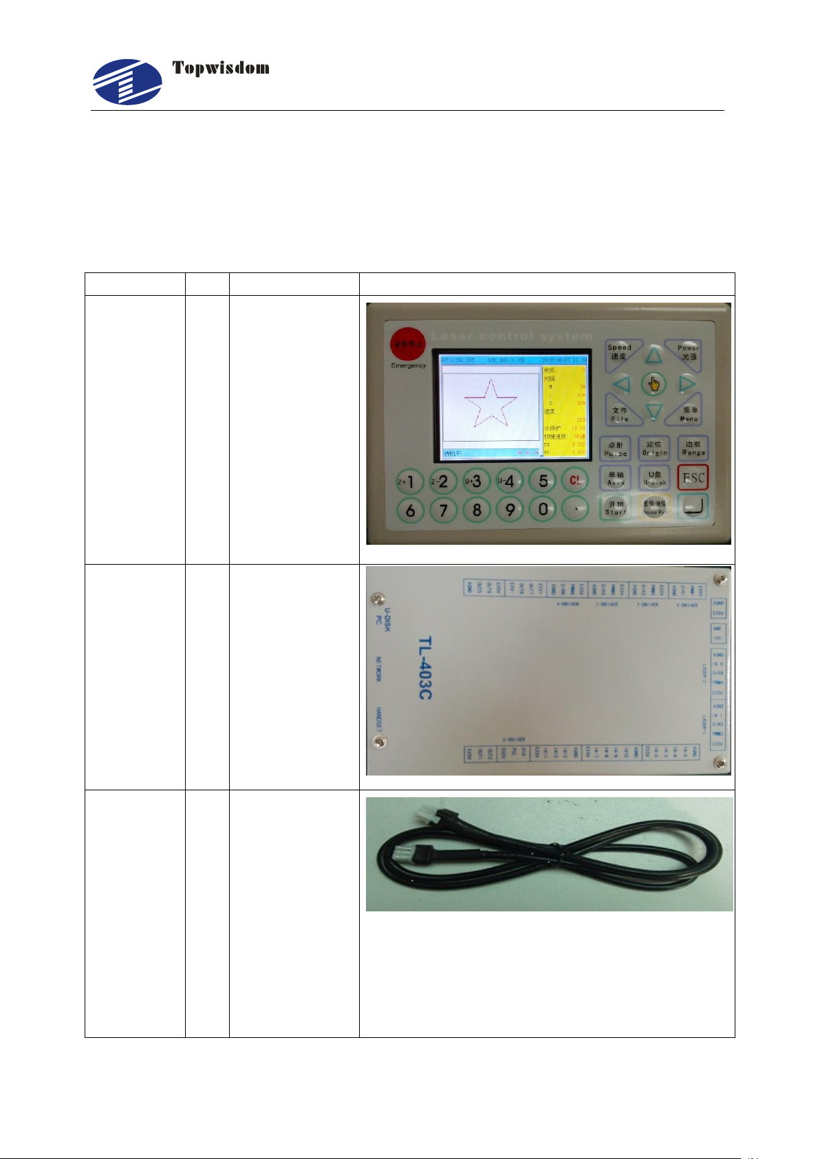
Name
Qty
Introduction
Photo
Operation
Panel
1
For user
operation
Controller
1
The Motion
Control Card
Connection
cable
3
1.Panel
Connection
cable for
connecting
controller and
panel.
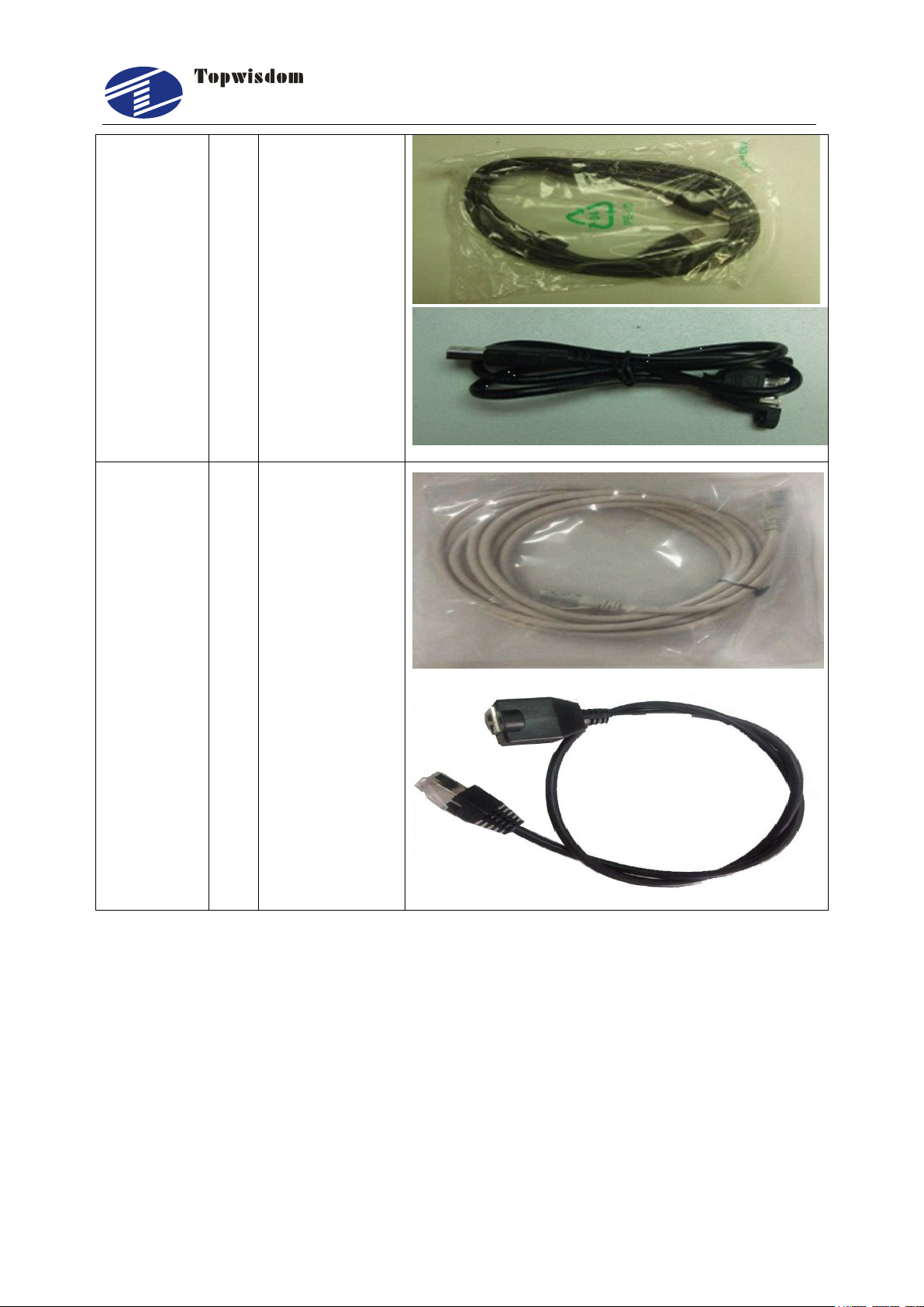
2.USB
communication
cable for
connecting
controller and
Grounding resistance is less than 100 ohms; the length of wire cable is within the
20meters, the cross-sectional area of the wire cable is larger than 1.0 mm2.
1.5 Accessory List
The Laser Engraving Control System-TL-403 contained the accessories as below:
泰智科技
Shenzhen Topwisdom Technology Co., Ltd
4
PC
3.USB
communication
extended cable
Crossover
Ethernet
Cable
2
1.Crossover
Ethernet Cable
2.Network
communication
extended cable
泰智科技
Shenzhen Topwisdom Technology Co., Ltd
5
PC
U-DISK
EX5V
EX5V
XGND
IN-5
XGND
OUT6
OUT5
OUT2
OUT1
EX5V
IN-2
IN-3
IN-4
XGND
EX5V
EX5V
PWM4
DIR4
XGND
IN 6
GND
+5V
EX5V
PWM3
DIR3
XGND
IN 1
LASER-2 LASER-1
EX5V
XGND
IN10
IN-7
IN-8
IN-9
EX5V
XGND
IN11
IN12
IN13
EXV+
EXV-
OUT7
OUT8
EX5V
XGND
PWM6
DIR6
EX5V
XGND
PWM5
DIR5
EX5V
XGND
PWM2
DIR2
EX5V
XGND
PWM1
DIR1
X-DRIVERY-DRIVERZ-DRIVERV-DRIVER
DIR
PUL
EX5V
TL-403C
HANDSET
NETWORK
Air Control
Pen Control
5V Relay
5V Relay
EX5V
DIR
PWM
DIR
PWM
- - + +
DIR
PWM
DIR
PWM
- - + +
DIR
PWM
DIR
PWM
- - + +
DIR
PWM
DIR
PWM
- - + +
Axis V Driver
(Laser head2 motor)
Axis Z Driver
(Feeding motor)
Axis Y Driver
(Y motor)
Axis X Driver
(X motor)
U-DRIVER
V Origin Limit
Z Origin Limit
U Origin Limit
Cover Protect
Foot Switch
X Origin Limit
Y Origin Limit
PWM
DIR
PWM
DIR
- - + +
Mechanical
Switch
DC 5V/3A
DC 5V/3A
Water Protect
Water Protect
TH
TL
WP
G
IN
5V
Two way
switch
RP100R
CO2
Laser
power
1
TL
G
IN
CO2
Laser
power
2
Axis U Driver
(Lifting motor)
Control
damper
Control
damper
Auto
Manual
Y Up Limit
X Up Limit
5Vo0V
Optoelectronic
Switch
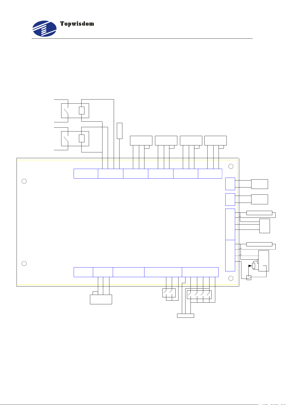
Part 2 Wiring Installation Instruction
2.1 System Wiring Diagram
Fig. 2-1
泰智科技
Shenzhen Topwisdom Technology Co., Ltd
6
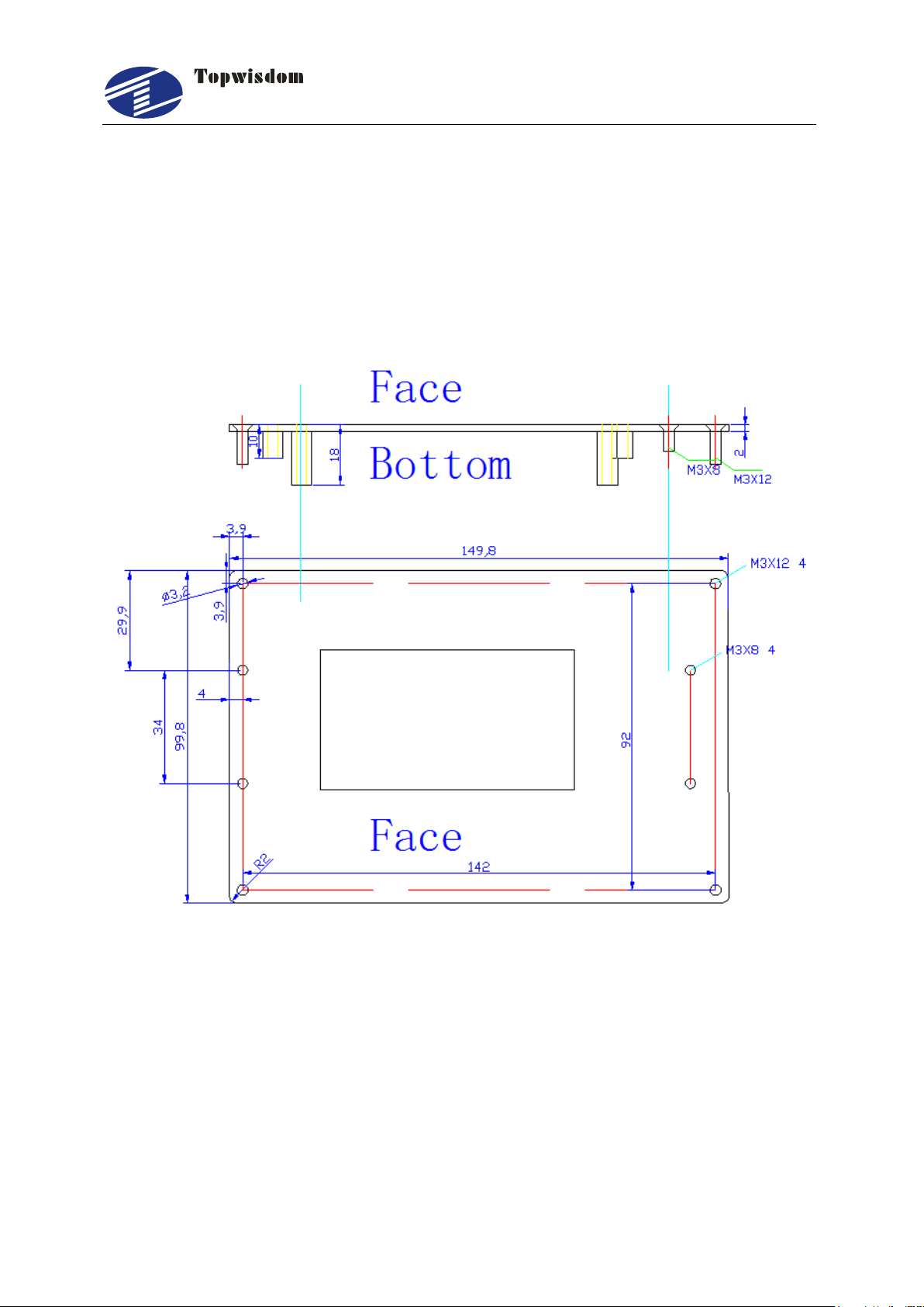
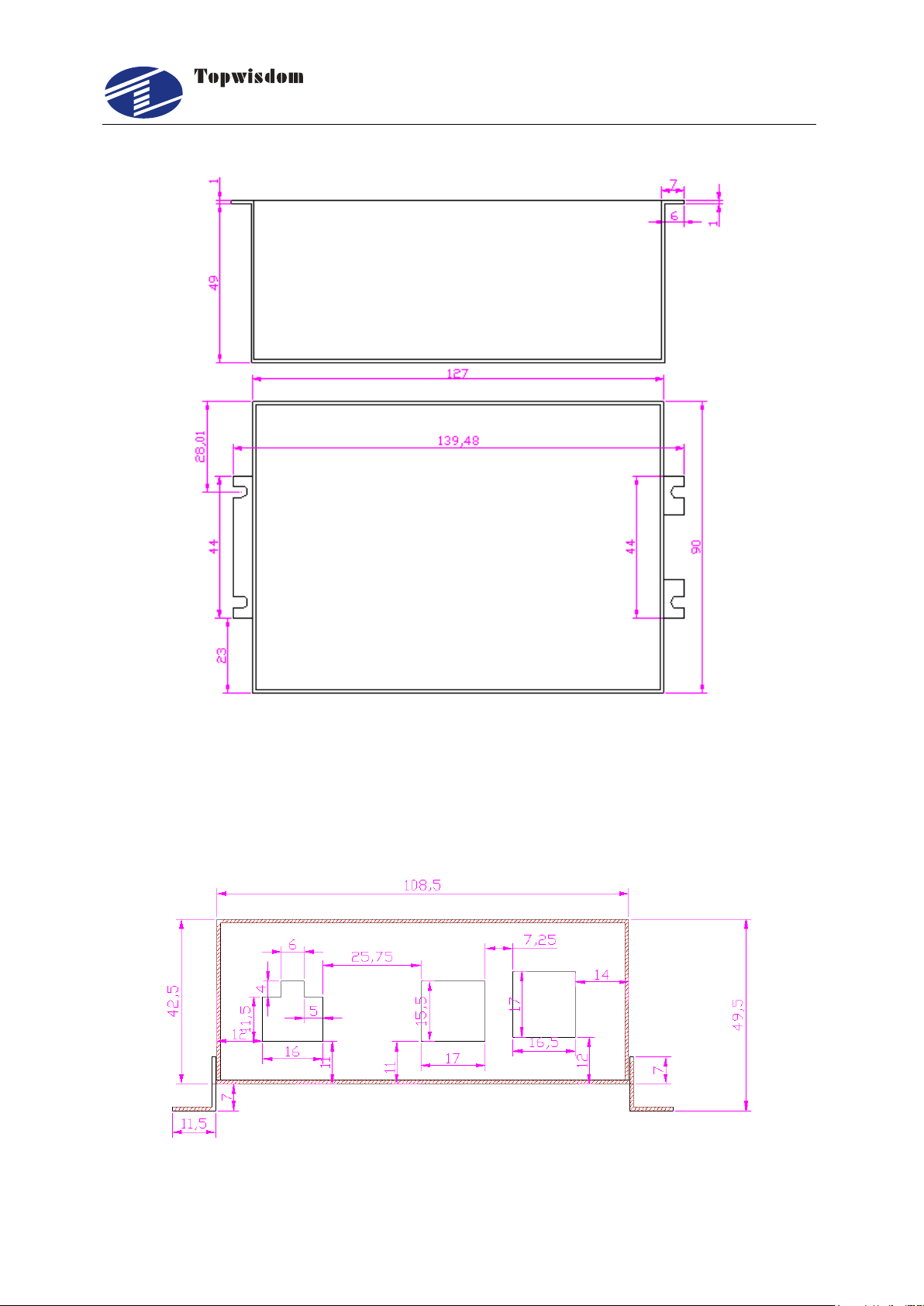
2.2 Installation Dimension
2.2.1 Panel
The installation dimension of operation panel (the unit is MM):
Face:
Fig. 2-2
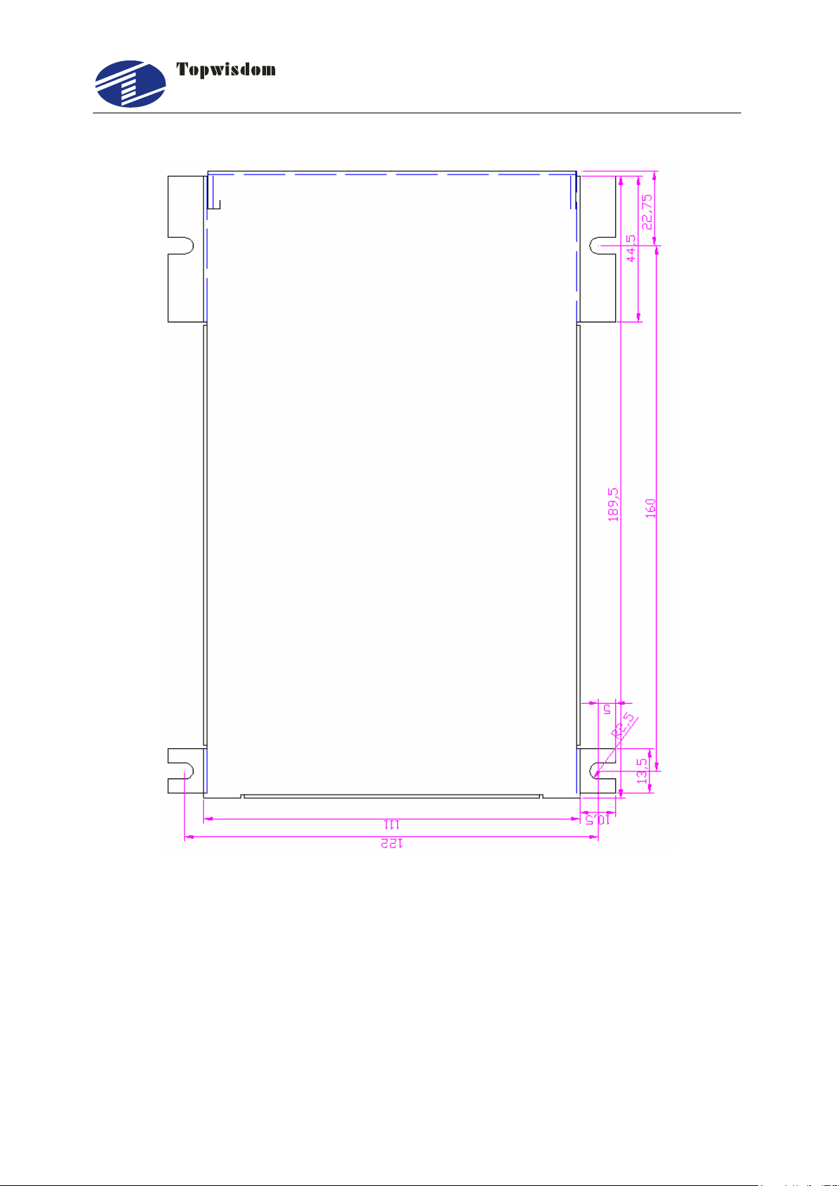
Bottom:
泰智科技
Shenzhen Topwisdom Technology Co., Ltd
7
Fig. 2-3
2.2.2 Mainboard
The installation dimension of mainboard (the unit is MM):
Fig.2-4
泰智科技
Shenzhen Topwisdom Technology Co., Ltd
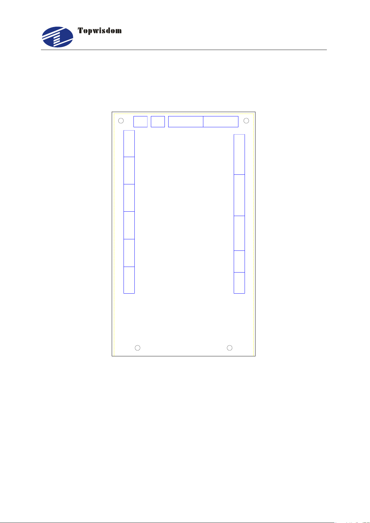
8
Fig.2-5
泰智科技
Shenzhen Topwisdom Technology Co., Ltd
9
PC
U-DISK
EX5V
EX5V
XGND
IN-5
XGND
OUT6
OUT5
OUT2
OUT1
EX5V
IN-2
IN-3
IN-4
XGND
EX5V
EX5V
PWM4
DIR4
XGND
IN 6
GND
+5V
EX5V
PWM3
DIR3
XGND
IN 1
LASER-2 LASER-1
EX5V
XGND
IN10
IN-7
IN-8
IN-9
EX5V
XGND
IN11
IN12
IN13
EXV+
EXV-
OUT7
OUT8
EX5V
XGND
PWM6
DIR6
EX5V
XGND
PWM5
DIR5
EX5V
XGND
PWM2
DIR2
EX5V
XGND
PWM1
DIR1
X-DRIVERY-DRIVERZ-DRIVERV-DRIVER
DIR
PUL
EX5V
TL-403C
HANDSET
NETWORK
U-DRIVER
2.3 Wiring Instruction
2.3.1 Interface Broad
2.3.2 Wiring Diagram
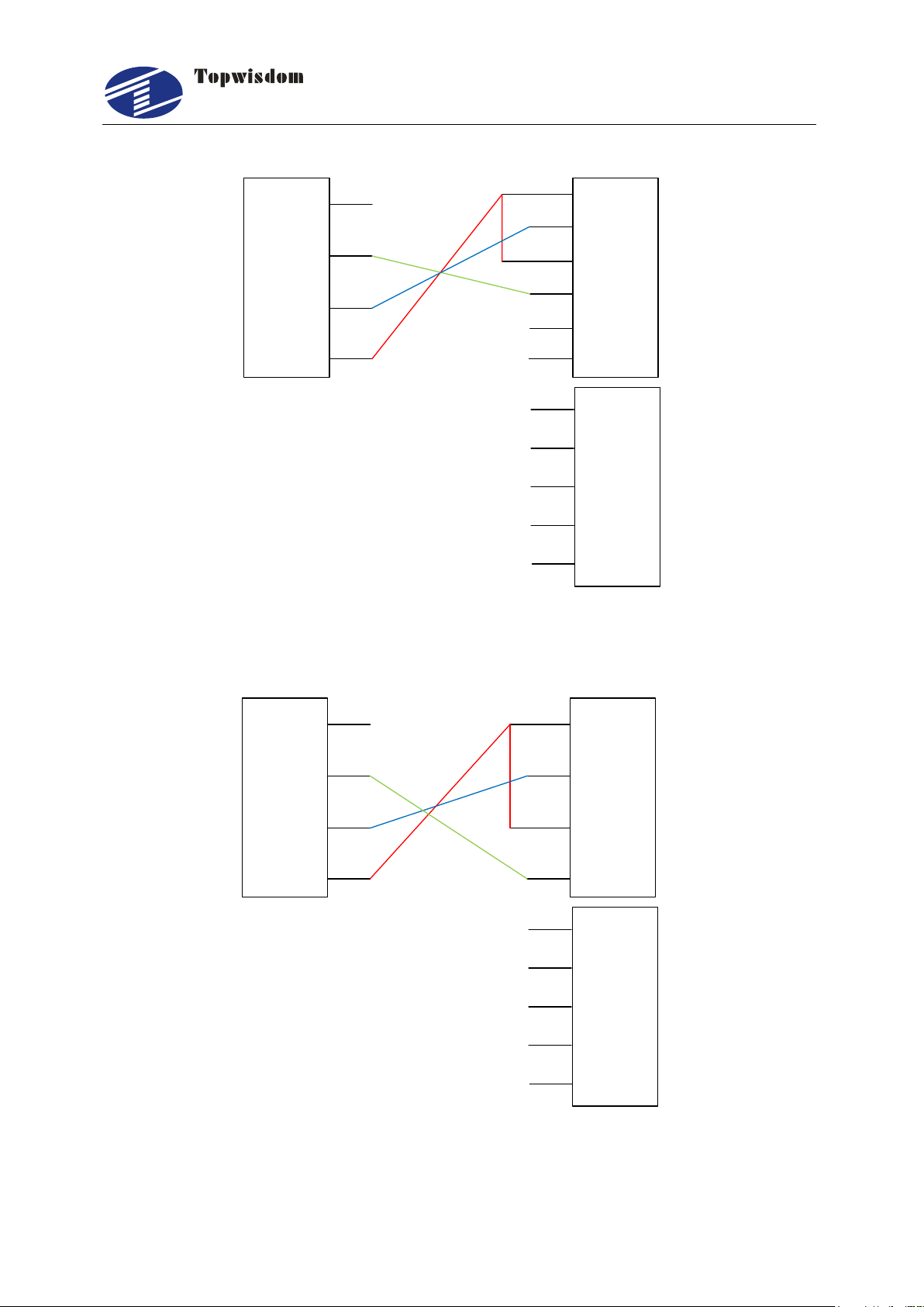
2.3.2.1 Motor Wiring
The following is X axis motor wiring, other axis are similar.
Fig. 2-6
1. Step Motor Wiring
泰智科技
Shenzhen Topwisdom Technology Co., Ltd
10
PUL+
PULDIR+
DIRENA+
ENA-
GND
DIR1
PWM1
+5V
GND
U
V
W
Vdc
36V-
To
Motor
36V+
J20 X Driver
PULS1
PULS2
SIGN1
SIGN2
GND
DIR1
PWM1
+5V
COM-
U
V
W
COM+
24V-
To
Motor
24V+
J20
Panasonic servo
3
6
5
4
41
7
2. Panasonic Servo Wiring
Fig. 2-7
Fig. 2-8
2.3.2.2 Laser Power Supply Wiring
泰智科技
Shenzhen Topwisdom Technology Co., Ltd
11
TTL-H TTL-L WP GND
DAC
1 3 4 5 62
Water Potect
EX5V PWM3 DIR3 IN-1 XGND
J2
Laser
Power
Supply
Active low
Power
Water Protect
EX5V PWM3 DIR3 IN-1 XGND
J2
Laser
Power
Supply
GND
1. CO2 Laser Power Supply Wiring
2.RF Laser Wiring
Fig. 2-9
Fig. 2-10
泰智科技
Shenzhen Topwisdom Technology Co., Ltd
12
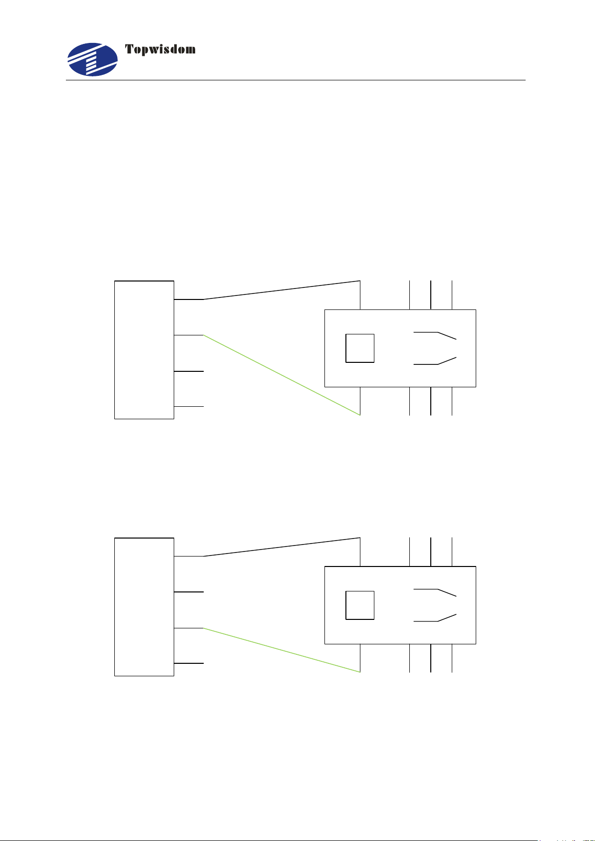
EXV-
OUT8
OUT7
EXV+
J9
5V/24V Relay
5V+/24V+
EXV-
OUT8
OUT7
EXV+
J9
5V/24V Relay
5V+/24V+
The wiring of laser 2 is similar.
Note:When “RF1 or RF2” is selected, please set the PWM Frequency according
to the data sheet of the laser. Generally, PWM Frequency is 5000Hz. And set the
Laser Max parameter not larger than 95%, especially not to set as 100%,
otherwise it works improperly.
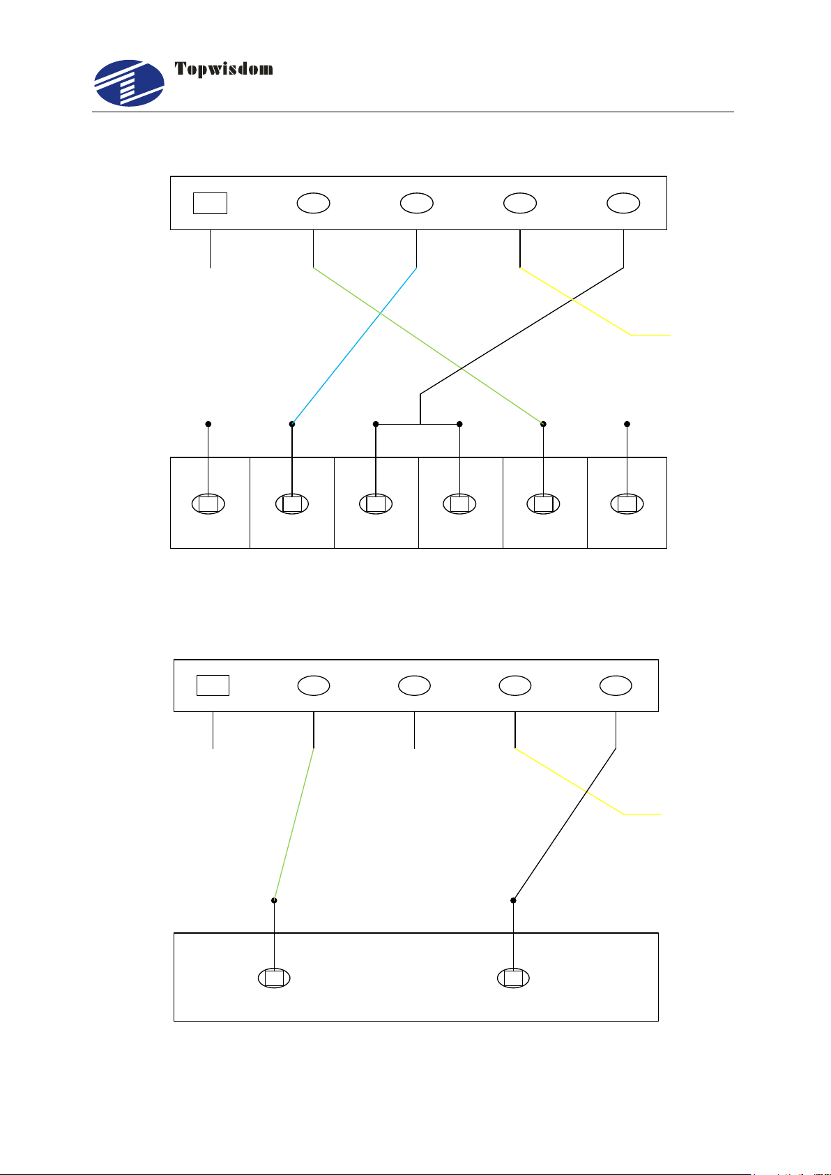
2.3.2.3 Blowing Air Signal Wiring
Fig. 2-11
2.3.2.4 Pen UP/Down Signal Wiring
Fig. 2-12
2.3.2.5 Limit Switch Signal Wiring
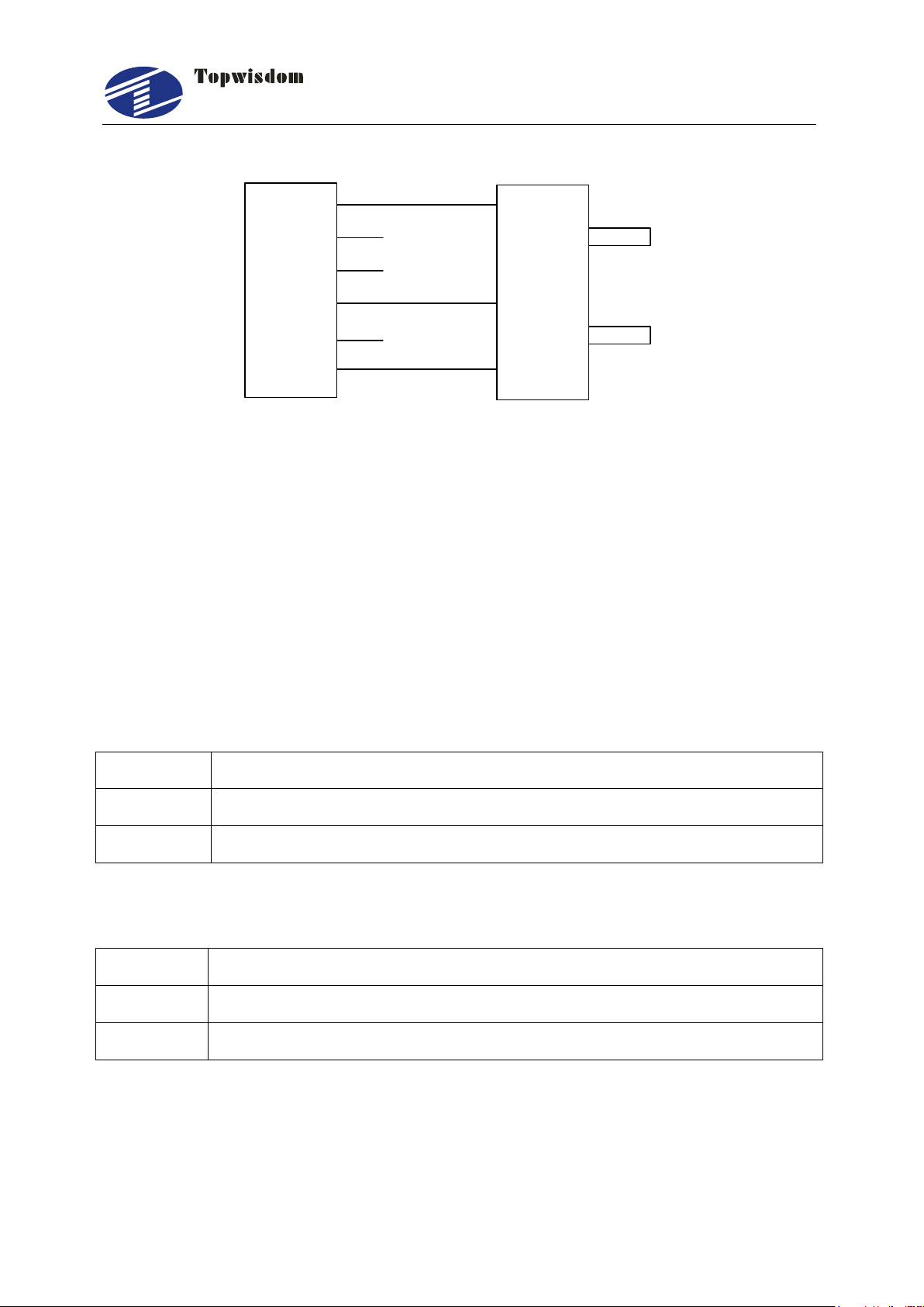
泰智科技
Shenzhen Topwisdom Technology Co., Ltd
13
XGND
IN-5
IN-4
IN-3
IN-2
EX5V
0V
OUT
5V
J3
Photoelectric limit switch
X Origin limit switch
Pin
Definition
1
+5V Internal 5V power source positive (input)
2
GND Internal 5V power source grounding (input)
Pin
Definition
1
EX5V External 5V power source positive (output)
2
XGND External 5V power source grounding (output)
Other limit switch wirings are similar.
Fig. 2-13
2.4 Interface Instruction
2.4.1 Power Signal
The system is dual 5V power supply
The system internal 5V power interface J24 (switching power interface)
The system external power interface J23 (switching power interface)

泰智科技
Shenzhen Topwisdom Technology Co., Ltd
14
Pin
Definition
1
EX5V External 5V power source positive (output) PUL+, DIR+
2
PWM1 Step pulse (output) PUL-
3
DIR1 Direction signal (output) DIR-
4
GND External 5V power source grounding (output)
Pin
Definition
1
EX5V External 5V power source positive (output) PUL+, DIR+
2
PWM2 Step pulse (output) PUL-
3
DIR2 Direction signal (output) DIR-
4
GND External 5V power source grounding (output)
Pin
Definition
2.4.2 U-DISK Port
Label U-DISK, can directly insert the U disk to read and write.
2.4.3 PC Connection Port
Label PC connection port, can connect PC to read and write with USB.
2.4.4 NETWORK Port
Label NETWORK, can connect PC to read and write by network.
2.4.5 Output
The driver interface
X axis interface J20
Y axis interface J18
Z axis interface J21

泰智科技
15
1
EX5V External 5V power source positive (output) PUL+, DIR+
2
PWM5 Step pulse (output) PUL-
3
DIR5 Direction signal (output) DIR-
4
GND External 5V power source grounding (output)
V axis interface J22
Pin
Definition
1
EX5V External 5V power source positive (output) PUL+, DIR+
2
PWM6 Step pulse (output) PUL-
3
DIR6 Direction signal (output) DIR-
4
GND External 5V power source grounding (output)
Pin
Definition
1
EX5V External 5V power source positive (output) PUL+, DIR+
2
OUT3 Step pulse (output) PUL -
3
OUT4 Direction signal (output) DIR--
Pin
Definition
1
EX5V External 5V power source positive (output)
2
OUT1 Work finish output signal
3
OUT2 Feeding output signal. When feeding, it outputs <1.0V voltage,
otherwise it outputs >3.0V voltage
Pin
Definition
1
EX5V External 5V power source positive (output)
2
OUT5 Press material output signal while feeding
U axis interface J11
Shenzhen Topwisdom Technology Co., Ltd
The general output interface
The general IO output interface J17
The general IO output interface J10 (expansion port)

泰智科技
Shenzhen Topwisdom Technology Co., Ltd
16
3
OUT6 Reserved
4
XGND External 5V power source grounding (output)
Pin
Definition
1
EXV+ Connect to pin 1 of J10 or external 5V/24V power source
2
OUT7 In the brush mode, lifting signal, high effective, connect to the
relay coil ―+‖ side
3
OUT8 Blow air signal, high effective, connect to the relay coil ―+‖ side
4
EXV- Connect to the relay coil ―-‖ side
Pin
Definition
1
EX5V External 5V power source positive (output)
2
PWM3 Be used to control the laser
When the laser is RF laser, used to control the power intensity and light of
the laser.
When the laser is domestic glass tube, used to control the electric current.
3
DIR3 Laser enable control (DIR3 jumper to H, the signal is high and
effective, to L, the signal is low and effective.)
When the laser is RF laser, used to control the enable function of laser.
When the laser is domestic glass tube, used to control laser On/Off.
4
IN-1 Laser status, the corresponding instruction is LED D1
When the laser is RF laser, used to the state input of laser.
When the laser is domestic glass tube, used to the state input of water
The relay control signal interface J9
The input voltage of relay has many kinds, such as 5V, 12V, 24V, but the 5V is the best.
2.4.6 Laser Power Interface
The interface of laser power 1 – J2

泰智科技
Shenzhen Topwisdom Technology Co., Ltd
17
conservation (active low).
5
XGND External 5V power source grounding(output)
Pin
Definition
1
EX 5V External 5V power source positive (output)
2
PWM4 Be used to control the laser
When the laser is RF laser, used to control the power intensity of the laser.
And Put the Jumper of s2/s4 to far away to battery.
When the laser is domestic glass tube, used to control the electric current.
3
DIR4 Laser enable control (DIR3 jumper to H, the signal is high and
effective, to L, the signal is low and effective.)
When the laser is domestic glass tube, used to control laser On/Off.
4
IN-6 Laser status, the corresponding instruction is LED D6
When the laser is RF laser, used to the state input of laser.
When the laser is domestic glass tube, used to the state input of water
conservation (active low).
5
XGND External 5V power source grounding(output)
Pin
Definition
1
EX 5V External 5V power source positive (output)
2
IN-2 X upper limit, axis movement to the max coordinate limit sensor
input
3
IN-3 X origin limit, axis movement to the minimum coordinate(0)limit
The interface of laser power 2 – J5
2.4.7 Input
The limit interface
X, Y axis limit interface J3

泰智科技
Shenzhen Topwisdom Technology Co., Ltd
18
sensor input
4
IN-4 Y upper limit, axis movement to the max coordinate limit sensor
input
5
IN-5 Y origin limit, axis movement to the minimum coordinate(0)limit
sensor input
6
XGND External 5V power source grounding (output)
Pin
Definition
1
EX 5V External 5V power source positive (output)
2
IN-7 Z origin limit, axis movement to the minimum coordinate(0)limit
sensor input
3
IN-8 U origin limit, axis movement to the minimum coordinate(0)limit
sensor input
4
IN-9 Opening protection signal input
5
IN-10 Foot switch signal input
6
XGND External 5V power source grounding (output)
Pin
Definition
1
EX 5V External 5V power source positive (output))
2
IN-11 U axis upper limit switch input
3
IN-12 U axis lower limit switch input
4
IN-13 V origin limit, axis movement to the minimum coordinate(0)limit
sensor input
5
XGND External 5V power source grounding (output)
Z, U axis limit interface J7
The general input interface
Input interface J4
When using the single laser control, the water protection signal of another laser must
be shorted with XGND, otherwise, the machine don’t work.
泰智科技
Shenzhen Topwisdom Technology Co., Ltd
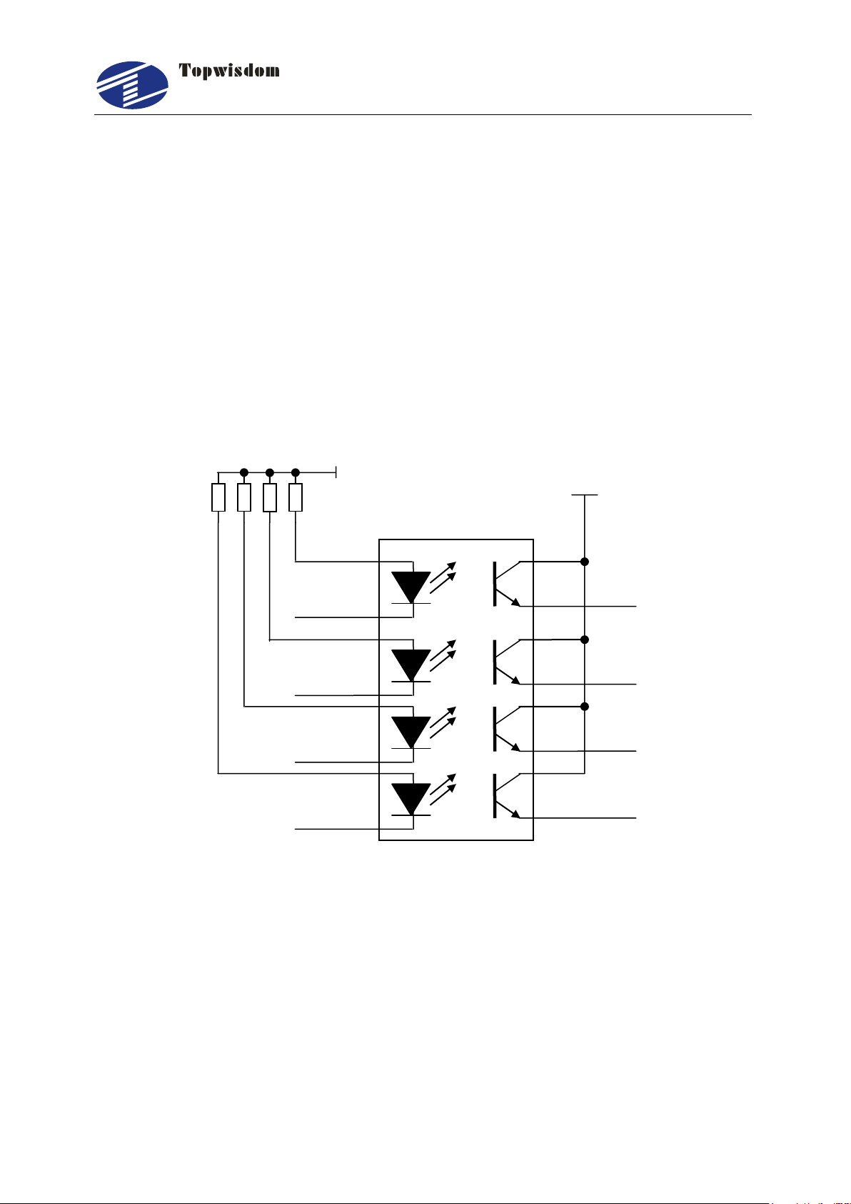
19
IN-1
IN-4
IN-2
IN-3
Input signal
+5V
+3.3V
The connection ways of switch input signal:
When using approaching switch, the corresponding parameters of upper PC must
be set as ―Negative‖ by NPN; the corresponding parameters of upper PC must be
set as ―Positive‖ by PNP.
When using straight or magnetic induction switch, the corresponding parameters
of upper PC must be set as ―Negative‖ while receiving signal + XGND;the
corresponding parameters of upper PC must be set as ―Positive‖ while receiving
signal + EX5V.
2.4.8 Input Signal Diagram
Fig 2-14
泰智科技
Shenzhen Topwisdom Technology Co., Ltd
20
Part 3 Software Installation
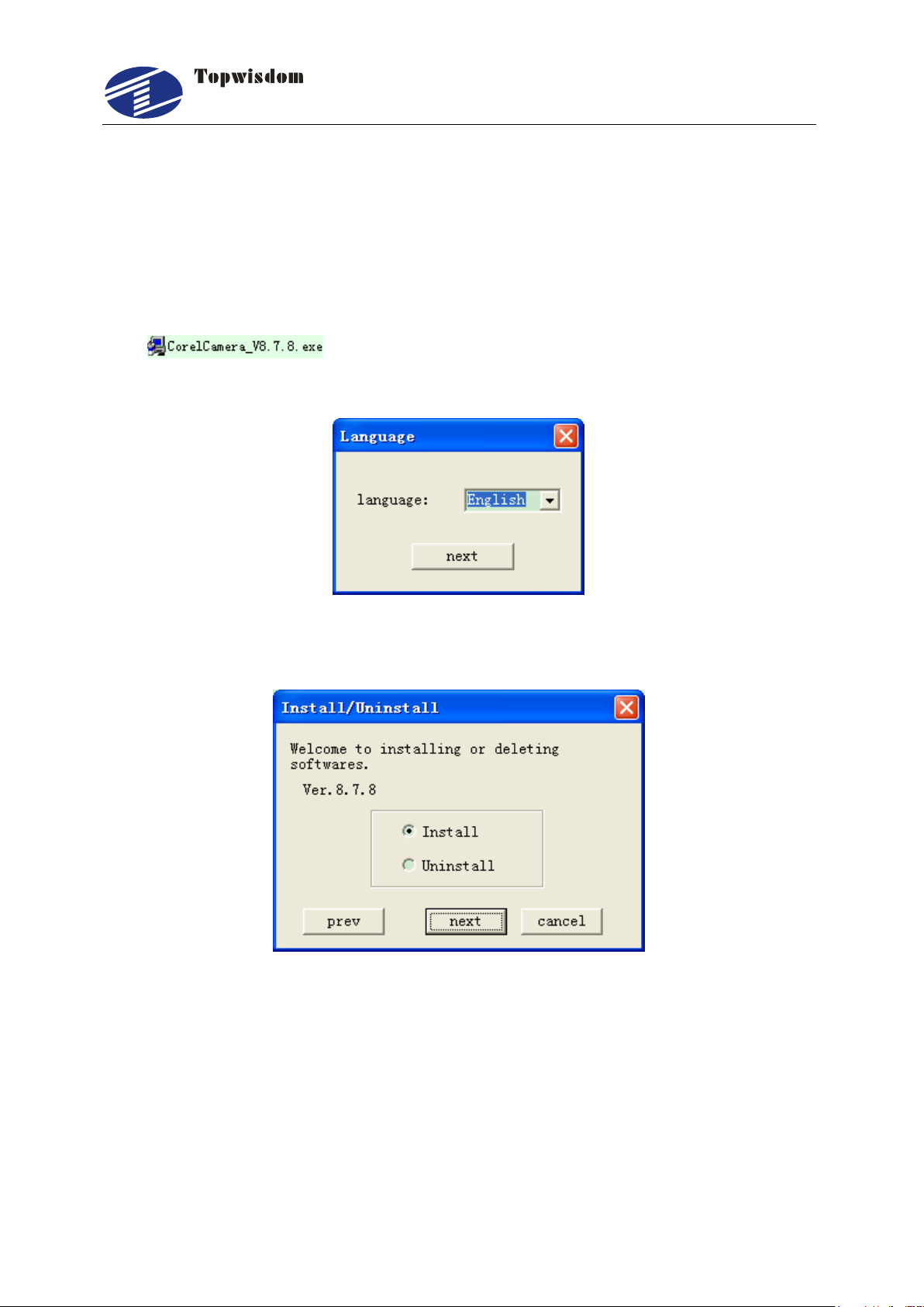
3.1 Installing CoreDRAW Direct Output
CorelDRAW12 or a higher version needs to be installed firstly. Then double click the
icon (below CorelCamera_V8.7.8 is used to introduce), a screen
shown in Fig. 3-1 will be displayed for selecting installing language.
Fig. 3-1
Click ‖next‖ to proceed with installation.
Fig. 3-2
Select ―Install‖ to install software, or select ―Uninstall‖ to uninstall software. Then click
next. And the screen shown in Fig. 3-3 is displayed.
泰智科技
Shenzhen Topwisdom Technology Co., Ltd
21
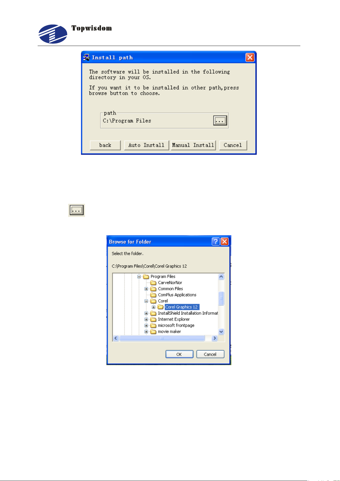
3.1.1 Manual Install
Fig. 3-3
Click the button to find the CorelDRAW install path, as shown in Fig.3-4, select
the Corel Graphics 12 folder as below.
Fig. 3-4
When the installed path is found, click the Confirm to go back to the screen shown in
Fig.3-3. Then click the ―Manual install‖ to install. W hen installation is finished, the
screen shown in Fig. 3-5 is displayed. Click ―OK‖ to finish.
泰智科技
Shenzhen Topwisdom Technology Co., Ltd
22
Fig. 3-5
3.1.2 Auto install
Click the ―Auto install‖ button shown in Fig. 3-3, the program will find the install path
automatically. When installation is finished, the screen shown in Fig. 3-5 is displayed.
Click ―OK‖ to finish.
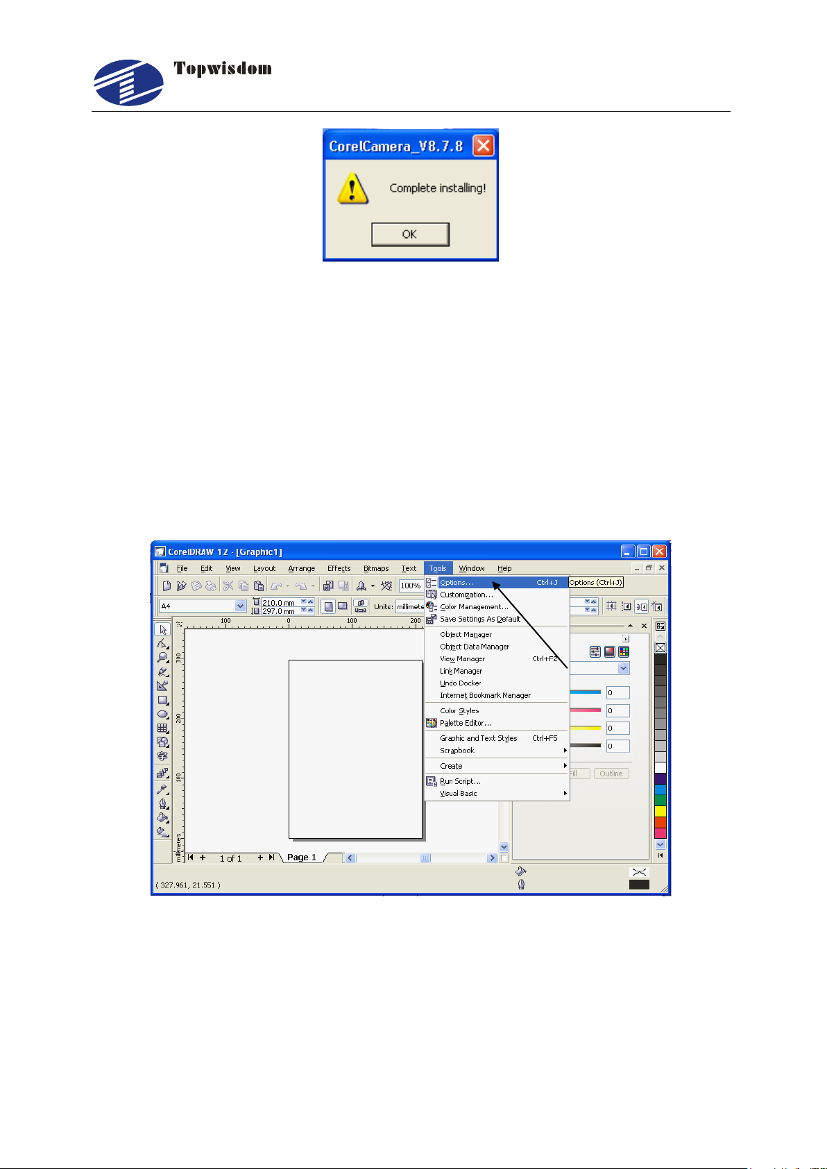
However, the installation is not really completed then, as you need to make
configurations for the CorelDRAW software, after the configuration the total installation
will be completed, then open CorelDRAW, it’ll show as below.
Fig. 3-6
Select ―Options‖ from ―Tools‖ in the toolbar shown in Fig. 3-6 to enter the menu shown
in Fig. 3-7.
泰智科技
Shenzhen Topwisdom Technology Co., Ltd
23
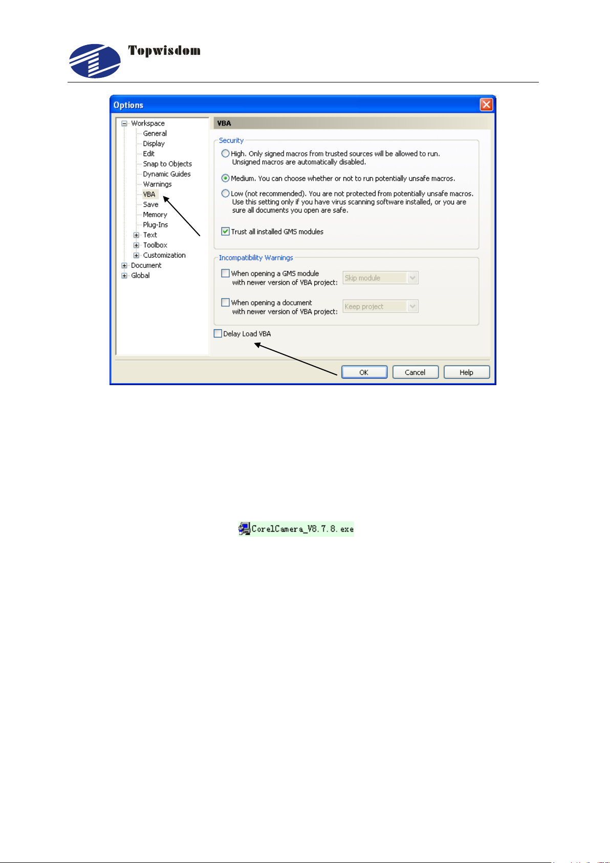
Fig. 3-7
In Fig. 3-7, first click on the ―VBA‖ as pointed out by the arrow in the left, then choose
the "Delay Load VBA" at the bottom, the installation is thoroughly completed.
3.2 Uninstalling CorelDRAW Direct Output
Double click on the icon of CorelDRAW Direct Output
installation software for uninstall, select ―Uninstall‖ and click the ―next‖ to uninstall the
software. The CarveNorNor folder in the root folder of CoreDRAW application and the
CORELSAVE_NOR folder in Draw folder can be manually deleted if it was needed.
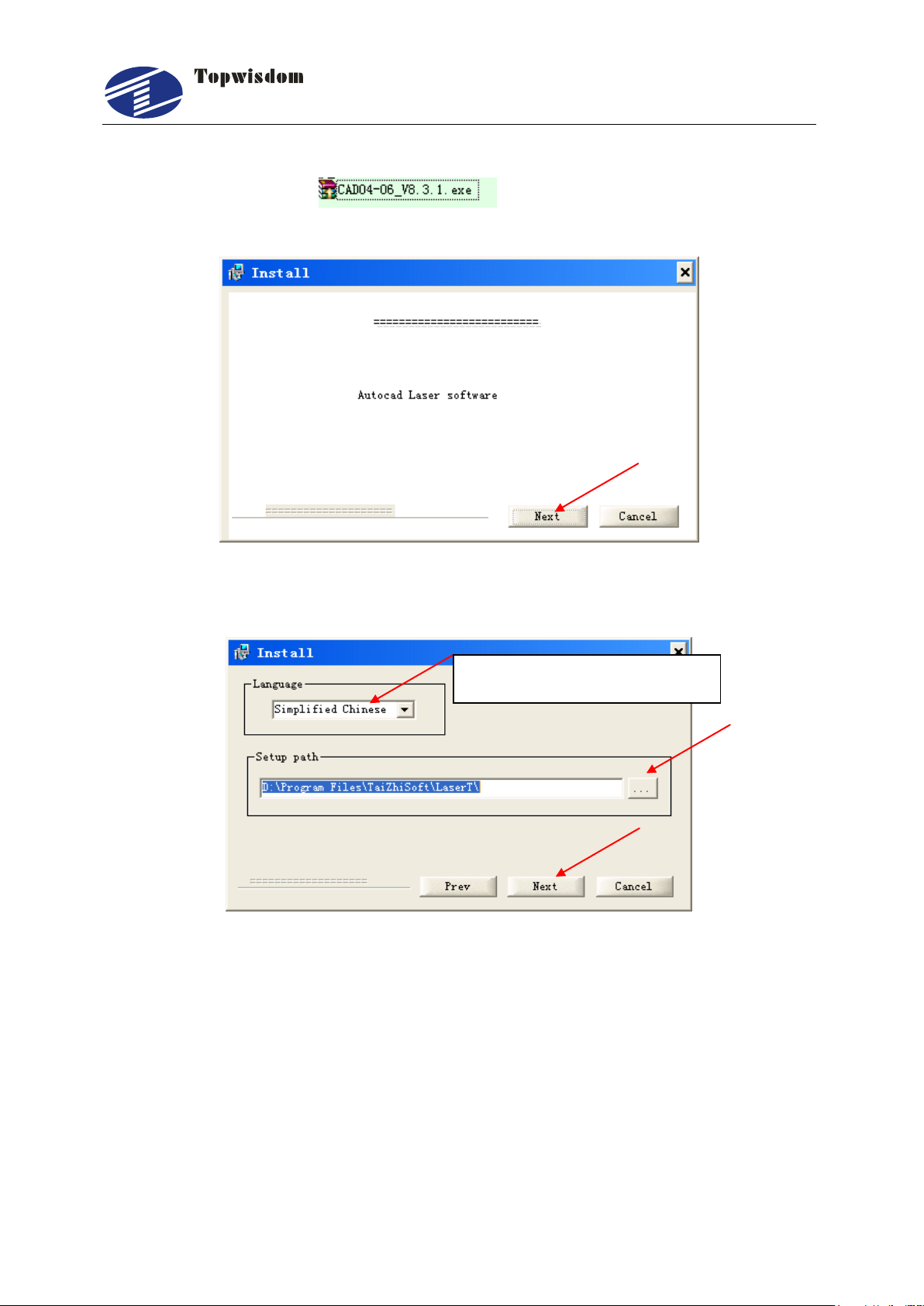
3.3 Installing CAD Direct Output
Now there are two CAD Direct output software available.
CAD04-06_V8.3.1.exe
CAD07-09_V8.3.1.exe
CAD04-06_V8.3.1.exe is for installing on AutoCAD2004-2006, now the current
software version is V8.3.1—the version is according which program you installed. The
version is shown in the installing program name, as you can see in
CAD04-06_V8.3.1—the version is V8.3.1. CAD07-09_V8.3.1.exe is for installing on
泰智科技
Shenzhen Topwisdom Technology Co., Ltd
24
Select the installing language
AutoCAD2007-2009.
Double click the icon , to unzip files, then the screen shown
in Fig. 3-8 is displayed.
Fig. 3-8
Click ―Next‖ to proceed with installation.
Fig. 3-9
When finished selecting language, click ―…‖ button to select the install path. Then click
―Next‖ to start installing, the installing screen shown in Fig. 3-10 is displayed.

泰智科技
Shenzhen Topwisdom Technology Co., Ltd
25
Fig. 3-10
When the installation is finish, the installing program will be closed automatically.
3.4 Uninstalling CAD Direct Output
Click the LaserT Uninstall, show as Fig. 3-11.
Fig. 3-11
Click ―Yes‖ to uninstall in Fig. 3-12.
Fig. 3-12

泰智科技
Shenzhen Topwisdom Technology Co., Ltd
26
Select ―No, not this time‖
Click the
"Next"
Fig. 3-13
3.5 USB Driver Installation
Insert the USB Cable, the power on, Fig. 3-14 will be shown on the Compute, and then
the Fig. 3-15 will be shown:
Fig. 3-14
Fig. 3-15

泰智科技
Shenzhen Topwisdom Technology Co., Ltd
27
Select ‖Install
from a list or
specific
location
(Advance)‖
Click the
"Next"
Click ―Include this
location in the search‖
Click
―Browse‖
Click
―Next‖
Click the "Next", show as Fig. 3-16
Click the "Next", show as Fig. 3-17.
Fig. 3-16
Fig. 3-17

泰智科技
Shenzhen Topwisdom Technology Co., Ltd
28
Select the usb
driver folder
Click OK
Browse to the USB driver folder by clicking the browse button. Once the file path has
been entered in the box, click next to proceed.
Fig. 3-18
The screen shown in Fig. 3-19 will be displayed as Windows XP copies the required
driver files.
After finishing, show as Fig. 3-20.
Fig. 3-19

泰智科技
Shenzhen Topwisdom Technology Co., Ltd
29
Click
Finish
Fig. 3-20
USB driver must be installed twice. Repeat the installation steps above once again.
3.6 USB Port Setting
After the engraving card power on, connect the PC with USB cable, the computer will
assign a COM port to communicate. But when the assigned COM port is more than
COM8, the communication will have problem, so we need to change the COM port
number, the range is among COM3~COM9.
3.6.1 View the assigned COM Port by Computer
Enter the control panel.

泰智科技
Shenzhen Topwisdom Technology Co., Ltd
30
Fig. 3-21
Double click the "System", show as Fig. 3-22.
Fig. 3-22

泰智科技
Shenzhen Topwisdom Technology Co., Ltd
31
The
assigned
COM port
Click the device management.
Fig. 3-23
Fig. 3-24

泰智科技
Shenzhen Topwisdom Technology Co., Ltd
32
3.6.2 Change the Assigned COM port by Computer
On Fig. 3-24 USB Serial Port(COM4) is the assigned COM port, the way and the steps
that change the assigned COM port are as follow:
Double click USB Serial Port(COM4), show a window, single click Port settings, show
as Fig. 3-25
Fig. 3-25
Click "Advanced", show a Advanced Settings for COM4 window, choose the port
numbers on the COM Port Number, show as Fig. 3-26.

泰智科技
Shenzhen Topwisdom Technology Co., Ltd
33
Fig. 3-26
Click "OK", display a window of Communications Port Properties, as Fig. 3-27
Fig. 3-27
Click "Yes" to finish.
3.7 IP Setting
Enter the control panel

泰智科技
Shenzhen Topwisdom Technology Co., Ltd
34
Double click network connection.
Fig. 3-28
Fig. 3-29
Double click "Local Connection".

泰智科技
Shenzhen Topwisdom Technology Co., Ltd
35
Double click TCP/IP setting.
Fig. 3-30
Fig. 3-31

泰智科技
Shenzhen Topwisdom Technology Co., Ltd
36
Select ―Use the following IP address‖, set the IP, Subnet mask, Default gateway, as
below figure.
Fig. 3-32

泰智科技
Shenzhen Topwisdom Technology Co., Ltd
37
Part 4 Software Operation Guide
4.1 CorelDRAW Direct Output Software Operation
Open the CorelDRAW software, show as Fig. 4-1
Fig. 4-1After startup, our processing buttons will be automatically mounted on the
menu shown in Fig. 4-1 as pointed out by the arrow. After completing the figure, we
can click on the ―Laser Carve‖ button as pointed out by the arrow in Fig. 4-1 to show
the menu in Fig. 4-2.
Fig. 4-2

泰智科技
Shenzhen Topwisdom Technology Co., Ltd
38
4.1.1 Layer Parameter Setting
It uses different colors for the configuration of engraving parameters, if there are
imported bitmaps, there will be independent bitmap settings. You can select a certain
color and double click or click on button ―Parameter Settings‖ for settings of these
drawings, and then the menu shown in Fig. 4-3 and Fig. 4-4 will be entered.
Fig. 4-3
Fig. 4-4

泰智科技
Shenzhen Topwisdom Technology Co., Ltd
39
The two most important parameter settings are Outline output and Carve output. If
neither of the two is selected, ―output disabled‖ will be shown, i.e., no engraving output
for this kind of drawings will be carried out; if both are selected, data in this color will be
provided with possibility of both Outline and Carve output, pay attention that there must
be closed drawings for Carve. Otherwise, select one of them for one output condition.
PrecisionUnit: the unit of precision of engraving.
DPI(dots/inch): dots per inch
DPM(dots/mm): dots per millimeter
SpeedUnit: the work speed and the free speed unit.
m/minute: meter per minute
mm/s: millimeter per second
PRI: Is used for setting the engraving order of different colors, the smaller PRI, the
earlier to be exported, and vice versa.
Those are common settings for colors. ―Outline‖ and ―Carve‖ menus are respectively
corresponding to settings for Outline and Carve. For Outline, there are settings for
engraving features including speed, power intensity etc., for dots, the dotting time
settings are also available; and the settings for Carve follow the same way.
When the check box of ―default‖ is selected, no need to set the power intensity and
speed and the default values of the machine will be adopted; settings for power
intensity and speed are only available in case the check box of ―default‖ is not
selected.
Parameters description:
Output: W hen selected, engraving output for drawings in the current color will be
carried out.
Min. Power: W hen stroking curves, this power intensity applied for line start and the
corner of the curve .Or it applied for the top depth when gradient carving. The range is
0.00-100.00% (Min.Power1 is setting for min power of laser1, Min. Power2 is setting
for min power of laser2. Max. power is similar).
Max. Power: W hen stroking curves, this power intensity is applied as the work speed
was reached. Or it applied for the bottom depth when gradient carving. The range is
0.00-100.00%. If the is elbow too deep, it means the Min. power intensity is on the high
side or the speed is on the low side. When gradient carving is carried out, the min
power must not be set bigger than 30%, the max power can be set bigger, for getting a
better degree of gradient carving effect. The gradient rang is 0-3mm.
Work Speed: The work speed of the laser head is cutting. The rang is 0.000 to Axis
X,Y limit speed.

泰智科技
Shenzhen Topwisdom Technology Co., Ltd
40
Free speed: The move speed of laser head when the laser is off. he rang is 0.000 to
Axis X,Y limit speed.
Default: If selected, parameters like power intensity and speed etc. will be in
accordance with what displayed on the machine.
Open/Close delay: open delay is applied for the head of the cutting line. And the close
delay is applied fo the tail of the cutting line. The range is 0-15s.
Open Air: when open air check box is click, the blow air signal is active when work is
start. There is two ways of blow air, one is the blow air signal is always active. The
other is when laser is on the blow air signal is active otherwise not active.
Z_AxisMoveSize(mm): the moving distance of lift axis before work start. W hen work
is finish lift axis move back to the original position. The steps to enable the automatic
lifting function is below: Click the AxisControl button at the bottom, then select the
Allow_zAxis.,and set the SelectAxis as Z, click OK to back to the parameter setting
interface, now it is able to modify the Z_AxisMoveSize. Attention: This function is use
to the case of cutting the material with various thickness. By adjusting the position of
laser head, to make the laser head move to the position of the laser focal length is
reach.
Hit_point: for hit point or drill on material. Firstly click the ―Hit_Point‖ check box. Then
set the Point_Interval—interval between dots—and the Hit_Time—laser on timer, unit
is second.
Spot Compen.: Spot compensation is for compensating the size lose resulting f rom
the spot is too much big. The unit is mm.
Reseau: In the carve page, it can set the engraving mode to reseau mode. The reseau
mod is suitable for closed vector graphics.when the Open_Reseau check box is
selected, three parameters below can be set:
Pattern: Round, Square, Triangle
Interval(mm): Interval between dots
Size(mm): the size of dots. When the pattern is round, the size is the length of
diameter. W hen the pattern is square, it is length of edge. When pattern is
triangle, ti is the edge of external rectangle of triangle.
Carve method:
X_Unilateralism: Engraving from one horizontal side, when move inversely ,the
laser is off. It can eliminate backlash and the processing effect is good, but the
processing time is longer.
X_Bidirectiona(recommended): Engraving from both horizontal sides. The
processing time is short. But because the machine generally exist backlash leads
to dislocation. At this time you need to set up a backlash or backlash list.

泰智科技
Shenzhen Topwisdom Technology Co., Ltd
41
Y_Unilateralism: Engraving from one vertical side, when move inversely ,the laser
is off. It can eliminate backlash and the processing effect is good, but the
processing time is longer.
Y_Bidirectional: Engraving from both vertical sides. The processing time is short.
But because the machine generally exist backlash leads to dislocation. At this time
you need to set up a backlash or backlash list.
Gradient(mm): the gradient length of gradient engraving, as shown in figure below.
When carry out gradient engraving, the top depth is determined by the min power. The
larger the min power, the deeper the top depth. The Depth from top to bottom is
determined by the max power. The larger the max power, the deeper the depth. The
gradient length determines the distance from the top to the bottom, the greater the
distance, the slope more flat.
Fig. 4-5
Precision: the precision of engraving. The unit is DPI or DMP. It means how many
lines will be processed per inch or per millimeter. For example, 500 DPI means it will
process 20 lines within 1 millimeter length. The greater the precision value, the deeper
the engraved depth.
ReverseRepair: use to compensate the backlash of the machine. The debug step is
as follows.
Draw three 50X50 rectangle in CorelDRAW, select the carve output check box in
parameter setting window. And set precision as 2 DPI, ReverseRepair as 0. Then
output the file to control card.
The actual processing effect is similar to the figure below. The length of first line
and second line dislocation in the middle rectangle is the compensated length.
Generally it is negative, according to the engraving effect to set it. As the figure
shown below, the length is -0.2mm. So the ReverseRepair is -0.2.
Fig. 4-6

泰智科技
Shenzhen Topwisdom Technology Co., Ltd
42
When finish setting the ReverseRepair, set the appropriate value of max power
and precision. Generally, 60W CO2 laser, 53.5 Focus lens, 350DPI is
recommended. The greater the precision, the longer the engraving time.
IntervalList: select the UseList check box then the IntervalList setting is applied to the
engraving file. In this case, the ReverseRepair is useless. The function of IntervalList is
similar to the ReverseRepair, use to adjust the engraving effect. In the list of
IntervalList, it can set the backlash in different speed. Because of working in different
speed, the backlash is different. The greater speed, the bigger the backlash.
After the parameter settings, the engraving output can be carried out, the
system will remember the last parameter settings to avoid repeated parameter
settings. For instance, if you set the red output power intensity at (50%, speed at
20%, no error compensation and PRI at 1), the same setting will be applied for
the use of the color red (if any) for the next time.
4.1.2 Coordinate Setting
According to actual situation, just click on the ―Coordinate‖ button in Fig. 4-2 to enter
the menu shown in Fig. 4-7. If the machine homing to the upper right, select Right-Top
in the group of coordinate.
Fig. 4-7

泰智科技
Shenzhen Topwisdom Technology Co., Ltd
43
Laser head
There is 9 location can choose. If you set the location in upper right, the output file will
be processed in the lower left side of the laser head. As shown in Fig. 4-8.
Fig. 4-8
4.1.3 Track Setting
Click the ―TrackSet‖ button in Fig. 4-2, a track setting window will be shown. It can set
the cutting order and the cutting start point of the line in different shape or layer. As
shown in Fig. 4-9.
Fig. 4-9.
ColorLayer: Select the color layer number you want to adjust. It will display all the
shapes in this layer in the upper left window.
Shape: Each shape has a serial number. It means its processed order in this layer.

泰智科技
Shenzhen Topwisdom Technology Co., Ltd
44
Select a serial number in the shape drop-down box. Then the shape with this number
will be displayed in the upper right window. And the red arrow shows the start process
point and the direction of cutting.
Show Order: Select show order check box. The serial number of the shape will be
shown side by the shape in the upper left window.
Auto Order: click the auto order button, the program will automatically optimized
cutting sort all shapes.
Step: Specify the start processing point of the shape. The unit is the line number.
When set the step as 1, click the ―StartPos‖ button once, the start processing point will
move forward 1 line segment on cutting direction.
Sequence: Specify the process order of the select shape. Set the proper value of
sequence, then click ok button. At this time, the upper left window will display the new
processing order of shapes (the Show Order check box is selected).
Enter Line: When Selected the enter Line check box, an extension line will be added
before the shape. It is used to avoid the laser light is not stable, lead to processing
problems. Set into the angle and length of enter line, click ok button below to complete
setting.
Out Line: When Selected the enter Line check box, an extension line will be added
after the shape. It is used to avoid laser burn twice at the same place of the start
position of close shape, lead to overcut problem. Set into the angle and length of out
line, click ok button below to complete setting. Generally, the enter line and the out line
is less than 10mm.
When finish setting, click the ok button in right bottom to save the configure.
4.1.4 Single Axis Operation
Click the ―AxisControl‖ button in Fig. 4-2, a track setting window will be shown. It can
separately operate the single axis moving, show as Fig. 4-10:

泰智科技
Shenzhen Topwisdom Technology Co., Ltd
45
Fig. 4-10
Firstly select the com port which is the USB port described in section 3.6. Then select
the axis you want to move. Set the move distance in MoveSize edit box and the move
speed in Speed edit box. If you need the laser on, set the laser power in Power edit
box and select the OpenLaser check box. Click Execute button to move. If you want
the axis move to the reverse direction, set a negative value in the MoveSize edit box.
4.1.5 Output Engrave
After the parameter settings, click on ―output‖ to enter Fig. 4-11
Fig. 4-11

泰智科技
Shenzhen Topwisdom Technology Co., Ltd
46
Parameter description:
Out Rows: The rows of the output shape.
Out Columns: The Columns of the output shape. By defaut, the row and column is 1,it
means the shape will be processed once.
Row Interval (mm): The interval size of row. The unit is mm.
Columns Interval (mm): The interval size of column. The unit is mm.
FeedingTimes: After finish one process, the machine can feed once. The feeding
times parameter determines how many time it will feed.
FeedingPerSize(mm): the feeding length.
Feeding delay: The delay time after feeding. The Unit is second.
Attention: These parameters above are applied to array process or repeat process.
Here, the row and the column is array parameters. If row is 2 and column is 1, then
2X1 array work file will be outputted. The row interval determines the distance between
two rows. The columns interval determines the distance between two columns.
Feeding Times, FeedingPerSize, Feeding delay is applied to the machine with feeding
equipment. Feeding Times is repeat work parameters. Click the ―>>‖ button for more
array setting. As shown in figure below, it can set the table size—table width and length,
work start position, row, column, row interval, column interval. Click the Import button
or Auto-filled button to preview. Click ok to save configure.
Fig. 4-12

泰智科技
Shenzhen Topwisdom Technology Co., Ltd
47
Translate Mode: The communication mode for download file from computer to control
card. If USB mode is selected, it can select the com port in the drop-down
box—corresponding to the visual serial port created in the Device Manager of the
computer. If Netware mode is selected, it can select the IP of the machine you want to
download file to. Or you can set click the button to add or modify the IP address of
the machine. If the control card is camera cutting card with the version is
V.L010.XXX, then the CCD Mode check box must be selected. Otherwise, the
output file will not be identified by the card.
Path:
Shortest path: The program will automatically calculate the shortest cutting path
of the output shapes. The following options can be set.
Work starting pos.: laser head work starting position (Left-Top, Left-Below,
Right-Top, Right-Below).
Convergence point: The data handle between ending position of the current
shape and starting position of next shape.
The starting point: The distance from ending position of current shape to
starting position of next shape is shortest. The free move time is shortest.
Smooth starting point: Select the optimal starting position of next shape
to realize smooth moving, avoid shake or dislocation
Original starting point: no change the starting position of the shape.
Sub-layer optimization: First according to layer order to sort. Then optimize
the cutting order inside the layer.
From the inside out: If the shapes have the containment relationship, the
inside shape will be cut first. This guarantee will not happen cutting error or
missing cutting.
Original Path: Not optimize the path, using drawing order.
Hori. Unidirectional: cutting from one horizontal direction for array process (T
shape).
Bi-level: cutting from bilateral horizontal direction for array process (S shape).
Row: When the select the Hor. Unidirectional or Bi-level, it can set the Row
parameter. It means the width of the partition optimization. If you want to cut
the shapes within 100mm range, set the row is 100mm. So the machine will
have cut all the shapes with 100mm row size, then it moves to cut next shape
within next row.
Merge adjacent: set this merged range so that two line will be merged into a line if

泰智科技
Shenzhen Topwisdom Technology Co., Ltd
48
they meet the requirements. This is helpful to reduce the nodes within a shape and
make the not closed graph to closed graph.
ClosedRepair: Set the compensated line length for compensating the process error
leaded by the mechanical parts. This is helpful to make the not closed graph to closed
graph.
Dislocation treatment: For avoiding closed graph processing dislocation
phenomenon.
Offset repair: W hen feeding, material will send partial due to mechanical movement.
Offset repair parameter is used to correct the feeding error. The unit is %, the greater
the value you set, the greater the compensation.
Split feed: If the graph is so long, it needs to split feed. Set the split length. And the
graph within the split length range will not be split. Make sure the dimension of the
length is not greater than Y, otherwise it will be forced to split. Under the specified
length, cutting out a layout of the graphics, and then feed, and then cutting the next
layout of the graphics. Generally, the split length is length of the longest graphic.
In the bottom of the window, there are some buttons. The description is following:
WorkTime: Predicting the processing time.
SpeedCorrect: Click it then it shows a speed setting window. Set the speed limit when
cutting the little graph. It is useful to avoid shake.
Fig. 4-13

泰智科技
Shenzhen Topwisdom Technology Co., Ltd
49
OutFromFile: Download the *.out work file to control card.
Save: Generate a work file from current drawing and save the work file in computer.
Output: Click it and a window is shown. Doc name is assigned by the program, can be
modified. Press ―OK‖ to download file to control card. After the completion of the
transfer, control card will beep on. Press File button on the card panel, you will find the
downloaded file at the last. Select it and press ―start‖ to process.
Exit: Close the output window.
Fig. 4-14
4.2 The Equipment Management
This section describes the parameter settings of the laser engraving software and the
operation of the parameter setting software. These settings are very important
because the parameters of the machine will decide the working status of the
engraver, therefore, please read carefully this chapter and do not make any
change before you completely understand the meanings of all the parameters.
Enter the machine parameter settings when clicking on the ―Equipment Manage‖ in Fig.
4-1 above.
Fig. 4-15

泰智科技
Shenzhen Topwisdom Technology Co., Ltd
50
The equipment parameters are the core settings of the engraver, the user needs not to
modify them in normal cases, if the modification is necessary, please prepare a backup
for correct parameters in advance, if the equipment cannot work normally after the
modification, you can rewrite the backup data into the engraver.
Open the parameter settings menu (Fig. 4-16、4-17). This software functions to make
settings for the equipment parameters of Topwisdom laser engraving software.
4.2.1 Toolbar
There are 3 buttons in the tool bar , respectively
representing: factory settings, open file, save file and exit.
Factory Settings: Reference values or limit values for the parameters set by the
factory, the user cannot modify the factory settings but can use them as reference.
Open File: Opens the backup parameter files saved in the computer.
Save File: Saves current parameters to a file.
4.2.2 Parameter Setting
See Figure Fig.4-16 for the factory settings

泰智科技
Shenzhen Topwisdom Technology Co., Ltd
51
Fig. 4-16
Port: It’s the communication interface between the computer and the equipment,
which is realized via the port, namely, the image information and the equipment
parameters on the computer are transmitted to the equipment via the port. Topwisdom
laser engraving software adopts USB interface or network for the connection with the
computer.
IP: Set the control card IP.
Netware mode: use network to communication.
CCD mode: for Camera cutting control card.
Read: Read the parameters saved in the equipment and display the values to the user
for reference. If you need to modify the parameters, you must read the parameters in
the equipment or open the parameter files already saved first, and then modify the
parameters (If read failure, please check if computer is connected to control card by
the USB cable or network cable).
Write: Write the parameter values set by the user into the equipment (authorizing code
provided by the manufacture is required: TZ0001), and then the equipment will operate
according to the parameters written into it. W hen the parameter settings of the
equipment is not completed, click on this button, and the ―Some Data is Invalidate‖ will

泰智科技
Shenzhen Topwisdom Technology Co., Ltd
52
be shown in the status bar at the bottom, the parameters cannot be written into the
machine.
Clear: Besides the drop-down box option, the rest of the parameter value will be set to
null, which is no parameter values.
※ Topwisdom software uses serial ports for writing and reading, therefore, once a kind
of software is using a serial port, other software cannot use this serial port.
Equipment Type: type of the used machine. There are mainly general engravers and
brand engravers.
Open_cover safeguard: If Yes is selected, whenever the cover is open by user,
machine will start the safety protective measures, to pause working. In the case of
equipment with safety protection, which do not use the open protection, user can also
will set the Open_cover safeguard parameter as "No". Such as test equipment, test
process, but this operation must be performed by the professionals, generally don't
recommend customers to use.
Laser Type: Select proper laser device type according to the laser device used by the
machine.
PWM Frequency: I.e., the power intensity frequency of the laser tube, this value
differs according to different types of the laser tubes; please consult the instructions for
the laser tube for details.
Least Light: The min. duty ratio supported by the engraver.
Most Light: The max. duty ratio supported by the engraver.
Laser Open/Close Delay: the delay parameter set to avoid the uneven edges of the
first Outline and the last Outline when the laser is on or off.
Laser on Delay: Because it takes a short period to start the laser, in order to make the
power and the laser head be started synchronously, the laser device is started before
the laser head. I.e., the Laser On Delay.
Laser off Delay: Because it takes another period of time to shut off the laser after
receiving the instruction, in order to avoid excessive engraving, the laser is shut off in
advance.
Least Pulse Width: The min. pulse width to be recognized by the laser device.

泰智科技
Shenzhen Topwisdom Technology Co., Ltd
53
Fig. 4-17
Direction Polarity: Classified into positive and negative, when the motion direction of
the motor disaccords with the direction control buttons on the keyboard, you can
change the direction polarity to make them consistent with each other.
Limit Polarity: Classified into positive and negative, when the motor cannot return to
the original position, you can change the limit polarity to make it normal.
Key Polarity: The buttons on the control panel correspond to directions of the motion
of the axes, if it moves to the right when you press the left, change the polarity.
Note: set the limit polarity first, then direction polarity, and key polarity last.
Movement Precision (µm): The move distance per pulse, the unit is µm. The
resolution of machines may be changed slowly due to different abrasion and other
factors of machines, the user may get the optimal value after multiple times of
debugging and settings.
Calculation of Resolution: Accurate Resolution = Current Resolution × Real Size/
WishSize.
Current Resolution: The resolution set at current operation of the equipment, i.e., the
resolution in the parameter settings of the equipment, which can be read from the

泰智科技
Shenzhen Topwisdom Technology Co., Ltd
54
equipment.
RealSize: The length on the effect drawing designed by the user, normally in whole
numbers but not exceeding the max. travel.
WishSize: The length of the track left by the engraver on the engraved material, which
can be measured by measuring tools.
Fig. 4-18
About the size of the measuring:
Draw a 30*30 rectangle to c alculate the resolution. When measuring, the width of the
laser beam needs to be considered. The processed reactangle is as shown in figure
below. Take the measured value of the X axis 34mm, and input 34 into the RealSize
edit box and 30 into the WiseSize edit box. Click ok the program will calcul ate out the
right resolution. Other Axis is similar. When calculate the resolution of Y, the RealSize
is the length of trace the beam moved.
Fig. 4-19
Test Precision(µm): This parameter is valid when the equipment is provided with the
closed-loop detection system, this parameter finally decides the errors between the
engraved dimensions and the designed dimensions, in this case, only the adjustment
of this parameter rather than the minute changes of the motion resolution will influence
the engraved dimensions.
This parameter is invalid when the equipment is not provided with the closed-loop
detection system. In this case, the minute changes of the motion resolution will directly
influence the engraved dimensions.

泰智科技
Shenzhen Topwisdom Technology Co., Ltd
55
Most Speed (mm/s): The max. speed allowed for single-axis movement. This value
decides the max. Engraving speed and cutting speed.
Stop Speed (mm/s): The speed of sudden stop during single-axis motion, i.e., the
motion stops speed.
If the stop speed is high, the equipment will get greater impact when stopping and
starting; the effect of engraving will be poor while the engraving efficiency will be high;
Most_Acc( mm/s2): Max acceleration of the axis, the ratio of change of speed. It is
the ability of speed change from one value to another value in unit time.
The higher the acceleration, the time of the speed from one variable to another is
shorter. And carving efficiency is high, but the impact of the equipment and equipment
abrasion is big;
Otherwise, efficiency is low, the impact of equipment and equipment abrasion is small.
The max acceleration must match the max speed. Then device will work in the best
state (that is, the equipment work with high speed and carved to obtain the very good
effect). In general, the user can set the parameters reasonable according to their
requirement for engraving speed and accuracy.
To meet the accuracy requirement of the user, it can improve the speed and
acceleration to make engraving efficiency.
If speed is now meet the requirements of users, or it was unable to reach the maximum
speed of current Settings, the user can appropriately reduce the speed value. Because
each user's environment and engraving requirement is different, so the device’s max
speed and the max acceleration will also be different. Users can obtain the best
parameters after repeated practice.
Max. Space: As either the bean or the guide rail has a fixed length, each machine has
a max working breadth (i.e., working range), which limits the motion of the machine
within the max working breadth and makes the trolley and the beam move within the
working range. The trolley and the beam will not hit the machine edge as there’s the
limitation of max space.
4.2.3 Embroidery Import
Embroideries Import is provided for the convenience of the user to import DST, DSB
files of format, the import of CAD files is opened here. Please see the figure below:

泰智科技
Shenzhen Topwisdom Technology Co., Ltd
56
4.2.4 Import bitmap
Fig. 4-20
If have a bitmap for engraving, click on the import bitmap button in Fig. 4-20, a Import
set window will be shown. If you need to change the bitmap into reseau diagram,
select the NetMode check box. You can set the direction of net point or the size of point.
Click OK button to import the bitmap.
Fig. 4-21

泰智科技
Shenzhen Topwisdom Technology Co., Ltd
57
4.2.5 Curve Precision
Set the curve accuracy with the software to improve the smoothness and speed of the
operation, you can select general, meddle, high, very high, most high, etc..
Fig. 4-22
4.3 CAD Direct Output Software Operation
Open the CAD software, show as Fig. 4-23
Fig. 4-23

泰智科技
Shenzhen Topwisdom Technology Co., Ltd
58
4.4 CAD Direct Output Software Supplementary Description
4.4.1 The Support of AutoCAD Direct Output Annotation Text
Text and annotations in CAD system are normally exported as auxiliary information,
therefore, in usual cases, you need not select text and annotations in the window
shown in Fig. 4-24. However, in special cases, e.g., the user needs to engrave the text
in the graphics, and even the annotations, for output, you can select corresponding
options in the window shown in Fig. 4-24.
First, you’d like to announce that we do not support text and annotations to a fractional,
however, there are some limitations, for example, we support 5, 6 types of large fonts,
settings for large fonts are as follows: first enter the menu shown in Fig. 4-24, select
Text Style in the ―Format‖ menu.
Fig. 4-24
Then you’ll enter the menu shown in Figure Fig. 4-25, select Use Big Font (U). And
then select the font file you required from the pull-down menu of Big Fonts (B), we
currently supports the following font files for Chinese: Fs.shx, gbcbig.shx, HT.shx,
Hztxt.shx and Khz.shx. So you must select one of the aforesaid files.

泰智科技
Shenzhen Topwisdom Technology Co., Ltd
59
Fig. 4-25
After the steps above, the settings are completed, but please do note that when
inputting text, as shown in the figure below, after the text inputting tool is selected, the
menu shown in Figure Fig. 4-26 will appear when inputting text.
Fig. 4-26
Then you just let it adopt the default font shown in Figure Fig.4-26. Do not select the
English fonts or Song typeface or boldface etc. from the pull-down menu, for those
may not be supported by our software temporarily. After this, our software can support
the engraving output of text in CAD interface.

泰智科技
Shenzhen Topwisdom Technology Co., Ltd
60
4.4.2 Carving Gradient Sketch Map
Fig. 4-27
4.4.3 Coordinate System
Fig. 4-28
Coordinate: Coordinate must match original position of the machine. On the same
machine can't literally change the coordinate system
Location: The position of laser head is the start position before cutting. As shown in
figure below, there are 9 locations of laser head relative to the position of graphic. The
red cross is the position of laser head.

泰智科技
Shenzhen Topwisdom Technology Co., Ltd
61
scan
drawing graphic
effect
Fig. 4-29
4.4.4 Supplementary Description of Carving
AutoCAD provides the Carving output, which only needs the contour of a drawing
instead of filling, which should be particularly paid attention to.
Please note that for drawings drawn in AutoCAD, the Carving in direct output is carried
out according to the contour, you need not to draw the drawings in the filled mode,
besides, there’s no difference between intaglio and incised inscription, Fig.4-30 shows
the effects of the origin drawing and the drawing after Carving output, as there’s no
difference of intaglio and incised inscription in vector graphics, you may get the effect
of incised inscription by drawing, please see Fig. 4-31 if there’s relation of inclusion
between two outline drawings in the same color, the effect shown in the drawing below
will be created. If multiple layers of drawings in the same color are included, the effect
will be as follows, its rule of Carving output is that: engraving the first layer, not
engraving the next layer, and then engraving the further next layer, and the rest may be
deduced by analogy. Please see Fig. 4-32
Fig. 4-30

泰智科技
Shenzhen Topwisdom Technology Co., Ltd
62
scan
drawing graphic
effect
scan
drawing graphic
effect
scan
drawing graphic
effect
Fig. 4-31
Fig. 4-32
From what described above, we may see that for Carving out of vector graphics, filling
is not needed, and there’ll not be this kind of influence between drawings in different
colors, as shown in Figure Fig. 4-33 drawings in different colors are in the relation of
inclusion, no influence on each other. There’s overlay between the two parts of
Carvings. We believe you may have deeper understanding for the Carving modes of
AutoCAD.
Fig. 4-33
4.4.5 Supplementary Description of Software and CAD Direct
Output
Announcement: This document is mainly purposed to provide some methods of
analysis and solutions for the disorder of the engraving for vector graphics, as the
applications are diversified, some problems cannot be completely solved by our

泰智科技
Shenzhen Topwisdom Technology Co., Ltd
63
3 1 2
software alone, Therefore, sometimes the user need to make improvements for the
drawing so as to make the operation of the machine in accordance with our ideas.
Some simple drawings may be connected and exported in order
See the figure below:
Fig. 4-34
In Fig. 4-34, we first draw the curve at the center from the left to the right, then draw the
line section on the right from right to left, finally, we draw the line section on the left
from left to right, according to the original output processing, the result will be as
follows.
Fig. 4-35
And the order of output by the equipment follows the numbers displayed in Fig. 4-35
the direction for each step of output is shown by the arrow. This effect is poor as its not
completed from the beginning to the end b one run.
There are 2 ways to solve this problem, 1: draw the drawings in order or combine them
with the merger operation provided in software like CorelDRAW or AutoCAD etc., 2:
our software engraving can change the order into a smooth and continuous way of
operating from the beginning to the end when processing the drawings.
The current software has make processing to drawings as shown in Figure 1 to mak e
them to be exported from the beginning to the end, i.e., this problem of output order
has been solved in the latest version of the software. However, we recommend our
users to draw the drawings in order when using AutoCAD or CorelDRAW etc., if you
fail to do that, you can combine them together with the merger operation provided in
the aforesaid software, which may provide higher fault tolerance.
Normalized output for complicated drawings are shown in Fig.4-36 below
Fig. 4-36
Fig.4-36 is not so complicated, however, according to our observation, many users will

泰智科技
Shenzhen Topwisdom Technology Co., Ltd
64
draw the figure in several sections instead of drawing it continuously, therefore, the
software will create multiple effects of output (this is relevant to the order of drawing of
different users), however, may be none of the effects is what you expect.
Please see the following sample for different effects of cutting.
Cutting 1 Cutting 2 Cutting 3
Cutting 4 Cutting 5
Fig. 4-37
As you can see in the drawings above, it totally takes 5 times to cut the entire drawing,
and the procedure is disordered. The effect is not expected, seeing from the stroking in
the drawings above, each Outline reaches the end and stops till there’s no connected
line section, but it is hard to choice the path in this way, and there’s also great
randomness, therefore, the entire drawing is divided into several parts. There’s little
software, currently, is provided with the capacity to manage the problems as a whole
like human being, for instance, cutting the external rectangle before the internal part
etc.. Therefore, we must pay attention to this kind of drawing when drawing, e.g., if you
want to cut the two rectangles along the 4 sides, you must combine the separate line
sections of the rectangles together with software, thus the disordered engraving will be
avoided and a relatively neat path will be achieved. Many users just patch up the
drawings Outline by Outline in irregular order, therefore, multiple types of stroking will
be created for a drawing as shown in Fig.4-34, which is actually very simple, while in
fact, there are many drawings much more complicated than this one, one joint may be
connected with many line sections, and the stroking will be more disordered, so it’s
hard to arrange the order effectively by our software alone, and you must solve the
problem from the beginning, the method of drawing.
Disordered output for single lines without joint or crossing
Fig. 4-38
Fig. 4-38 seems to the same to Fig. 4-34 at first view; however, the engraving is
disordered, why? Let’s amplify the drawing and you can see that there’s no joint

泰智科技
Shenzhen Topwisdom Technology Co., Ltd
65
between the line sections, so the order cannot the arranged. Therefore, when drawing,
pay attention that the joints must be closed.
No display when opening the drawing in a 3rd party engraving software, or run into a
wall when using CAD for direct output.
For example, you draw a drawing in CAD, which looks normal, while it cannot be
displayed in a 3rd party engraving software, or run into a wall when exported to the
equipment. Why? This is normally caused by a small drawing or dot far away from the
drawing, which is not what the user expects to process but is just drawn by mistake,
this makes the whole drawing to be so large and cannot be seen when opened in
another software after zooming out, and the breadth of output will be far exceeding the
operation breadth of the equipment, which will also cause problems.
Part of the drawings of CAD direct output or in DXF files cannot be displayed and
processed
AutoCAD2005 is newly provided with region tools and table tools, parts of a closed
drawing can be processed into the drawing of a region via the region tools on the left.
Then the software cannot recognize and process it, so pay attention that there should
not be any region drawing when drawing, if there are some, they should be redrawn by
line sections or curves or be broken up with breakup operation. Tables drawn with the
table tools should follow the same way, they can be normally exported after being
broken up, those are all new features after AutoCAD2005.

泰智科技
Shenzhen Topwisdom Technology Co., Ltd
66
Part 5 The Operation Panel
5.1 The Panel Operation and Buttons Function Introduction
5.1.1 The Panel
Fig. 5-1
5.1.2 Buttons Function Introduction
1. ―Emergency Stop‖ key: no matter what state the machine, click the key, it’ll
be into reset state, then return the origin point.
2. ―Speed‖ Key: Set the speed.

泰智科技
Shenzhen Topwisdom Technology Co., Ltd
67
3. ―Power Light Intensity‖ Key: Set the laser powers.
4. ―Menu‖ Key: Press the key into the main menu interface.
5. ―File‖ Key: Into the memory file selection interface.
6. ―U Disk‖ Key: Into the U disk file selection interface.
7. ―Range (frame)‖Key: The range previewed interface.
8. ―Pulse‖ Key: Use to test, touch a time, light a time, used to test the optical
path.
9. ―Origin‖ Key: Can set the start point from which the machine runs. The
―Origin‖ can be freely chosen on the Machine setting parameters. If choose the
―Mechanical Origin‖, after the machine reset, it’ll return the origin, the coordinate
is ―0, 0‖. If choose the ―Regression Point‖, after resetting, it’ll return the current
coordinate that machine operated last time.
10. ―Single Axis‖ key: into the single axis movement interface.
11、 ―Enter‖ Key.
12. ―ESC‖ Key.
13. ―Start‖ Key.

泰智科技
Shenzhen Topwisdom Technology Co., Ltd
68
14. ―Pause/Run‖ Key: press the key to pause at the working state, again press,
it’ll go to running. On the Pause state, after moving the X or Y axis, touch a
time, it’ll be automatically return the origin to continue working. On the Stop
state, press the key, the laser head will automatically return the regression
point.
15. — Number Keys, change the data the selected area, also can directly
press the key to choose the current menu.
16. Decimal Key.
17. Delete key.
18. Z axis moving key, in the Processing and Event into interface to move
the Z axis.
19. U axis moving key, in the Processing and Event into interface to move
the U axis
20. Direction key, used to move the X, Y axis, in the other
interfaces, used to move the curse to choose menu.
21. Choose key, change the axis speed in the standby interface, in the other
interface, used to change the parameters besides the numbers.

泰智科技
Shenzhen Topwisdom Technology Co., Ltd
69
System Init ...
Speed:
Valid:
KeySpeed: Middle
PX:
200
1V 2X:
Idle... 00 00 00::30PY:
0 000.
0 000.
12345678 OUT.
N etwork Disconnect
2014 03 10 10 58- - :
Complete:
Power1:
1
5
30
Power2:
5
File working
progress bar
The work
time
Status
The completed
number of file
The power of
laser
The working
speed
File Name
Time
5.2 The Main Interface Introduction
5.2.1 Power Interface
Fig.5-2
The system is initializing, please wait…
5.2.2 Standby Interface
After initialization, it’ll into the standby interface, show as:
The top of the interface shows the file name, network status, the date and time. The
white area shows the preview of the selected file. And the yellow area shows the
Fig. 5-3

泰智科技
Shenzhen Topwisdom Technology Co., Ltd
70
complete times, default power ,speed of the machine., the water protect status ,the
speed of key moving, and the position of axis x and axis y. And at the bottom left of the
interface, it show the machine status and the last working time.
The parameters are described below:
Network status: If connect the network, it’ll show the IP address196.168.0.100.
Otherwise, it shows Network disconnect.
Complete: The complete times of the selected file.
Power1: The power of Laser 1. The above value is min power value. The following
value is the max power value.
Power2: The power of Laser 2. The above value is min power value. The following
value is the max power value.
Speed: It shows the work speed.
Valid: The water protection status. In the figure, the water protection is 1X: 2X, 1X
means water protection 1 not connected, 2X means water protection 2 not
connected. If connect, it’ll show 1V:2V.
Key Speed: Manually move axis speed, can press the ―Select‖ key to change the
speed, there are ―Fast‖, ―Middle‖, ―Slow‖.
PX, PY: The coordinate in the current place.
When there is no file Selected, It displays the default power and speed. When
selecting the file, it shows the power and speed in the first layer of the file. When
processing, it shows the power and speed of the current processed layer.
When the machine is processing, if you want to modify the speed of the current layer,
press the pause button, then press speed button, you can modify the speed of the
current layer. In the same way, press power button to modify the min/max power. If
machine is processing, press ―Left/Right‖ button, can immediately reduce or increase
the laser power. Press once, plus or minus 1%. Left for reduce, Right for increase.
When changed the speed of power during working operation, after the completion of
processing, it prompts whether to save the changes of the speed and power value.
In standby mode, press to clear the completed number of selected file. If the
focus length was set in laser parameter interface, press to auto focus. If the
firmware version is V.L010.16 or later which is for camera cutting machine, press the
to start lable cut.

泰智科技
Shenzhen Topwisdom Technology Co., Ltd
71
Pa ram
3 I d le S pe ed m m s. ( / )
2 W o rk S pe ed m m s. ( / )
4 S p ee d Fa ct o r.
300
25.
1 L a ye r Pa ra m. 0
Sa ve ESC
200
5.2.3 Speed Setting Interface
After initialization, press the ―Speed‖ key, show as:
Fig. 5-4
This shows the speed setting is effective when the speed of working file set as
defaulted.
Layer Param:W hen one file is selected, press button,to choose the layer
number.
Work Speed: When one file is selected,it shows the work speed in current layer.
Otherwise, it shows the system default speed value. The unit is mm/s.
Idle Speed: The default move speed when laser is off. When one file is selected,
it shows the idle speed in current layer. Otherwise, it shows the system default
speed value. The unit is mm/s.
Speed Factor: It is applied to improve the smoothness of movement. The range is
0.00-5.00. The smaller the factor, the slower of planned speed of lines in work file,
and then the smoother of movement when turning corner. Normally it is set to 2.5. If
the smoothness is high demanded, set the factor to less than 1.
5.2.4 Power Light Intensity Interface
After initialization, press the ―Power‖ key, show as:

泰智科技
Shenzhen Topwisdom Technology Co., Ltd
72
返回保存
3.最 小 光 强 ( % )2
参数
2.最 大 光 强 ( % )1
1.最 小 光 强 ( % )1
42.最 大 光强 ( %)
ESCS ave
4. ( % )P o we r Mi n2 5
30
Pa ram
3 P o we r Ma x1. ( % )
5. ( % )P o we r Ma x2 30
2 P o we r Mi n1. ( % ) 5
1 L a ye r Pa ra m. 0
Canc elOK
Rang e
200
2 R u n Sp ee d m m s. ( / )
1 I f L as er O n. NO
5. ( % )P o we r Mi n2
5
304. ( % )P o we r Ma x1
6. ( % )P o we r Ma x2
30
3 P o we r Mi n1. ( % )
5
Fig. 5-5
Layer Param:W hen one file is selected, press button,to choose the layer
number.
Power Min: When stroking curves, this power intensity applied for line start and the
corner of the curve .Or it applied for the top depth when gradient carving. The range
is 0.00~100.00%.
Power Max: W hen stroking curves, this power intensity is applied as the work
speed was reached. Or it applied for the bottom depth when gradient carving. The
range is 0.00~100.00%.
Power Min1 is the min light power of LASER-1. Power Min1 is the max light power of
LASER-1.It is the same as Power Min2 and Power Max2 of LASER-2. When no file is
selected, the power value is the system default power value. When pulsing, the Power
Max will be used.
5.2.5 Range Preview Interface
After initialization, press ―Range‖ key, show as:
Fig. 5-6

泰智科技
Shenzhen Topwisdom Technology Co., Ltd
73
Middle
NO
0
0
0
0
0
Run
2 If L aser On.
1 Key S peed.
3 X Axis Setting.
4 Y Axis Setting.
5 Z Axis Setting.
6 U Axis Setting.
7 V Axis Setting.
返回ESC
If Laser On: Set run scale with or without laser on. Press ―Choose‖ key to set the
value.
Run Speed (mm/s): The speed of running scale, unit is mm/s.
Power:When cutting the scale, it uses the system default power which is shown
here. The min power intensity applied for line start and the corner of the curve. The
max power intensity is applied as the run speed was reached. Power Min1 is the
min light power of LASER-1. Power Min1 is the max light power of LASER-1.It is
the same as Power Min2 and Power Max2 of LASER-2.
5.2.6 Single Axis Movement Interface
After initialization, press ―Axis‖ key, show as:
Fig. 5-7
Press the ―Up/Down‖ key to choose the needed operation:
Key Speed: fast, middle, slow.
If Laser On: Yes or No?
X Axis Setting: Press ―Right/Left‖ key to move X axis, when stop, it’ll show the
current coordinate. The other axis operation is similar.
When If Laser On parameter is set as Yes, it uses the system default power to cut. No
selecting file and press Power button to modify the system default power.
5.2.7 File Selection Interface
Press ―Menu‖ key into the main menu, and select the Memory File button. Also can
directly press ―File‖ to enter, show as:

泰智科技
Shenzhen Topwisdom Technology Co., Ltd
74
Memo ry File Network Disco nnect
0 0 1 1 2 3 4 56 78 O U T 1 K: .
0 0 2 1 2 3 4 56 78 O U T:. 1K
0 0 3 1 2 3 4 56 78 O U T:. 1K
0 0 4 1 2 3 4 56 78 O U T:. 1K
0 0 5 1 2 3 4 56 78 O U T:. 1K
0 0 6 1 2 3 4 56 78 O U T:. 1K
0 0 7 1 2 3 4 56 78 O U T:. 1K
0 0 8 1 2 3 4 56 78 O U T:. 1K
0 0 9 1 2 3 4 56 78 O U T:. 1K
0 1 0 1 2 3 4 56 78 O U T:. 1K
Total File 25 :
Selec t File :20
ESC
20 1 4 03 1 0 11 00- - :
No Sel File .
ESCOK
4 D e le te.
Memo ry File
3 W r it e to U di s k.
1 R e ad F il e.
5 D e le te A ll.
2 F i le E di t.
Fig. 5-8
Press ―Down/Up‖ to choose the file, press ―Select‖ key to find the current file, press
―ESC‖ to quit, press ‖Enter‖ to operate, show as:
Reading File: Select this file to work.
File Edit: Edit the file parameters like speed and power.
Write to U Disk: Copy the file into U disk
Delete: Delete the current file
Delete all: Delete all memory files.
5.2.8 U disk File Interface
Press ―menu‖ key into the main menu, and select the U Disk file. Also can directly
press ―U disk‖ to enter, show as:
Fig. 5-9

泰智科技
Shenzhen Topwisdom Technology Co., Ltd
75
U Disk F ile Netwo rk Disconnect
0 0 1 1 2 3 4 56 78 O U T 1 K: .
0 0 2 1 2 3 4 56 78 O U T:. 1K
0 0 3 1 2 3 4 56 78 O U T:. 1K
0 0 4 1 2 3 4 56 78 O U T:. 1K
0 0 5 1 2 3 4 56 78 O U T:. 1K
0 0 6 1 2 3 4 56 78 O U T:. 1K
0 0 7 1 2 3 4 56 78 O U T:. 1K
0 0 8 1 2 3 4 56 78 O U T:. 1K
0 0 9 1 2 3 4 56 78 O U T:. K 1
0 1 0 1 2 3 4 56 78 O U T:. 1K
2 0 1 4 0 3 1 0 11 0 0- - :
ESC
Selec t File:20Total File 25 :
ESCOK
U D i sk F il e
1 W r it e to m e m o r y.
2 D e le te.
Fig. 5-10
Press ―Down/Up‖ to choose the file, and press ―Select‖ key to point the current file,
then click ―Enter‖ key or ―ESC‖ to quit, show as:
Fig. 5-11
Write into memory: Copy file from U Disk to control card.
Delete: Delete file.
5.2.9 The Main Menu Setting
Press ―Menu‖ into the main menu, show as:

泰智科技
Shenzhen Topwisdom Technology Co., Ltd
76
Main Menu Netwo rk Disconnec t 2 0 1 4 0 3 1 0 1 1 0 0- - :
OK
U Disk F ile
Memo ry File S y s Info. .
File S et
Inte grate System Test
返回
File S et
2 S a v e a s C u rS el.
1 S a v e T y p e.
ESCSav e
3 S a v e a n d E xe cu t e.
4 F i l e W o r k Mo de.
General
Yes
General
Yes
Fig. 5-12
Press the ―Up/Down/Left/Right‖ key to choose the needed setting, ―Enter‖ to operate,
and ―ESC‖ to quit.
5.3 File Setting
After starting, press ―menu‖ into the main menu, choose the ―File Set‖, then press
―Enter‖, show as:
Fig. 5-13
Press ―Up/Down‖ to choose the required operation, click ―Select‖ key to change setting,
press ―Enter‖ to save the setting, click ―ESC‖ to quit.
Save Type: General or Temp Save. Temp Save means the received file is
temporary file. It will be replaced by the new received file. General means the
received files will be saved one by one, not be replaced.

泰智科技
Shenzhen Topwisdom Technology Co., Ltd
77
Inte grate Network Disco n nect 2 014 03 10 11 00- - :
ESC
Laser S et
Equipment
Axis Set
Back S et Use r Set
Save as CurSel: Once a file is finish downloading, it will be select as current file.
Save and Execute: Once a file is finish downloading it will be executed.
File Work Mode: General or Cyc. Cyc means All the Files will be executed one by
one in cycle.
5.4 The Integrate Settings
After finishing the start, press ―Menu‖ key into the main menu interface, choose
―Integrate‖, then press the ―Enter‖ to enter, show as:
Press the ―Up/Down, Right, Left‖ to select the needed operation, click ―Enter‖ to enter,
click ―ESC‖ to quit.
5.4.1 Laser Set
In the Integrate Setting interface, choose ―Laser Set‖ to enter, show as:
Fig. 5-14

泰智科技
Shenzhen Topwisdom Technology Co., Ltd
78
1
0
La ser S et
2. P WM F re q u e n c y( HZ )
1. L as er T y p e
3. L as er M i n ( % )
4 ax. L a se r M ( % )
5. P WM D IR
6.Focus Leng th(m m)
ESCSav e
100
20000
20 1 4 03 1 0 11 00- - :
CO2
Positive
Fig. 5-15
Press the ―Up/Down‖ key to select the needed operation. Press the ―Choose‖ key to
change setting, ―Number‖ keys to set the value.
Laser Type: The common laser (CO2 glass tube), RF1, and the RF2. RF1 is for RF
laser without pre-ionize. RF2 is for RF laser with pre-ionize that will output 1us
tickle pulse.
PWM Frequency (HZ): Press the ―Number‖ keys to change the PWM.
Laser Min/Max (%): Range: 0≦the min duty ratio ≦the max duty ratio ≦100.
PWM DIR: Press ―Choose‖ to change the PWM DIR. If you found when you set
power bigger, the intensity of laser beam is stronger. Then you should change the
PWM DIR.
Focus Length (mm): Press the ―Number‖ keys to change the focus length. When
this parameter is set. Press ―.‖ Dot key in standby interface, a message box will be
shown that if reset focus length. If press ―Enter‖, the laser head will go down
controlled by U Axis. When sensors close to the material surface, reach the
designated position, a signal is given to controller, then it controls the laser head
move up to the focus position.
Attention: if laser type is RF1 or RF2, set the PWM Frequency to 5000, Laser Max
to 95%, not to 100%, otherwise the laser would always be on or off.
5.4.2 Equipment Set
In the Integrate interface choose ―Equipment‖ to enter, show as:

泰智科技
Shenzhen Topwisdom Technology Co., Ltd
79
Equipment P aram
2 L a s e r C ar M od e.
1 T a b l e M o de.
3 E q u i p m en t Ty p e.
4 B u z z e r S et ti n g.
ESCSav e
1
20 1 4 03 1 0 11 00- - :
General
Common
Single
Fig. 5-16
Press the ―Up/Down‖ key to select the needed operation. Click on the ―Choose‖ key to
change setting, ―Number‖ keys to set the value.
Table model: General or Double. After choosing double table model, and set the
Table Size parameter–the distance of double table model, the distance subjects to
the two upper left corner of table model. The machine on double table has two
tables: to go back and forth by Z axis, keep a table on the working position; and
another one turn in there on the both sides of machine.
LaserCar Mode: Single, Double1, Double2. Single means it just has one laser
head. Double1 means it has two laser heads on one belt. Double2 means it has
two laser heads with two belts. After choosing Double1 or Double2, need to set the
Double Head Intv. parameter—which is the origin points between the two laser
head. The X axis and V axis are used to control the two laser head movement. The
X axis control the laser head near the origin of the machine, V axis control the laser
head away from the origin of the machine. The X axis range is set to the maximum
width of the machine can be processed. V axis range is set to X axis range minus
the distance between two laser head. W hen it’s even column, the two head will
work at the same time; when it’s odd column, one head on the last column work.
Equipment Type: Common, Round (machine with wheel).
a. When choose the wheel device, need to set the parameters: Reference
Diameter and Reference Resolution.
Reference Resolution instructions:
a. Menu/Integrate/Equipment: Set the Equipment to Round. The ―Reference
Diameter‖ and ―Reference Resolution‖ are used to calculate the actual
resolution with the different cylindrical materials.
b. Reference Parameters

泰智科技
Shenzhen Topwisdom Technology Co., Ltd
80
Because cylindrical materials with different diameter, the range and the
resolution of Y axis is different. So the controller provides a reference
diameter and reference resolution for convenience to calculate.
After the reference diameter and reference resolution set correctly, each
time replace material, it just needs to set the ―Diameter‖ parameter in main
menu interface. Then the resolution and the max range of Y axis will be
recalculated according to the ―Reference Diameter‖ and ―Reference
Resolution‖. It means you just need to set the new material diameter.
c. The Modification of Reference Parameters
Set the Equipment to Round. You will see the Reference Diameter and
Reference Resolution have a default value. Measure the diameter of a
material for processing. Input this diameter into the ―Reference Diameter‖
parameter. The Reference Diameter can remain as default value or input
the estimate value to it, 10um for example.
Set the laser max power low to draw out one 50mm length line on the
surface of material. Measure the actual length of the line, 55mm etc. Go
into the Menu/Integrate/Axis set/ Y Axis interface, set the resolution of Y
Axis to reference resolution value. Then follow the normal steps to modify
the resolution. Press ―Choose‖ key to display a window to calculate the
resolution. Set want size to 50, real size to 55 in the resolution window.
Press ―Enter‖ key to calculate the right resolution as 11um, etc. Then Set
the ―Reference Resolution‖ to 11um. Finish setting.
d. Next time you replace the new material with different diameter, just set the
―Diameter‖ parameter in Main Menu interface.
Buzzer Setting: Press ―Number‖ keys to set the times.
5.4.3 Axis Set
In the Integrate Setting interface, choose ―Axis Set‖ to enter, show as:

泰智科技
Shenzhen Topwisdom Technology Co., Ltd
81
Axis Set 2 0 1 4 0 3 1 0 1 1 0 0- - :
ESC
X Ax is
Y A x i s Z A x is
U A x i s V A x i s
15
880
X Ax is S ettin g
2. ( / )Max Spe ed mm s
1. ( )Resolution um
3 m m. ( )St op Sp eed
4 A c c m m s 2. ( / )
5 J e r k m m s 3. ( / )
6 M a x R a n g e m m. ( )
7 A x i s D i r.
ESCOK
6000
12000
500
2 0 1 4 0 3 1 0 11 0 0- - :
N e g a t i v e
1 0 0.
10
Fig. 5-17
Press the ―Up/Down‖ key to select the needed operation, for example, the X axis
setting:
Fig. 5-18

泰智科技
Shenzhen Topwisdom Technology Co., Ltd
82
X Ax is S ettin g
9. Key Dir
8 L i m i t P N.
ESCOK
N e g a t i v e
N e g a t i v e
2 0 1 4 0 3 1 0 11 0 0- - :
10 Lim it Pr otec tion.
C l o s e
Fig. 5-19
Press the ―Up/Down‖ key to select the needed operation. Click on the ―Choose‖ key to
change setting, ―Number‖ keys to set the value.
Resolution: the resolution = the length that the laser head moving when the motor
rotate a cycle×1000 / the pulses that the driver output when the motor rotate a
cycle.
About measurement:
Draw a 30*30 rectangle to c alculate the resolution. When measuring, the width of the
laser beam needs to be considered. The processed rectangle is as shown in figure
below. Take the measured value of the X axis 34mm, and input 34 into the Want Size
edit box and 30 into the Want Size edit box. Click ok the program will calculate out the
right resolution. Other Axis is similar. When calculate the resolution of Y, the Real Size
is the length of trace the beam moved.
Max Speed (mm/s): The maximum speed allowed for single-axis movement. This
Stop Speed (mm/s): The speed of start or stop during single-axis motion, i.e., the
Acc (mm/s2): The Max acceleration of this axis, the bigger the acceleration, the
value decides the max. Engraving speed and cutting speed.
Fig. 5-20
motion stops speed.

泰智科技
Shenzhen Topwisdom Technology Co., Ltd
83
Axis Set 2 0 1 4 0 3 1 0 1 1 0 0- - :
ESC
X Ax is
Y A x i s Z A x is
U A x i s V A x i s
Message
OK
Cancel
Pulse Dir
shorter the work time, and the stronger jitter of motion.
Jerk (mm/s3): The acceleration of the acceleration change from the minimum
acceleration to upgrade to the maximum acceleration—Or the changed from the
maximum acceleration reduce to minimum acceleration during slowdown..The
smaller the jerk, the weaker the jitter of motion, the slower of acceleration and
deceleration. Otherwise, the jitter is stronger, the accelerating and decelerating is
the faster.
Max Range (mm): Maximum distance for axis can move.
Direction Polarity: Classified into positive and negative, when the motion direction
of the motor disaccords with the direction control buttons on the keyboard, you can
change the direction polarity to make them consistent with each other.
Limit Polarity: Classified into positive and negative, when the motor cannot return
to the original position, you can change the limit polarity to make it normal.
Key Polarity: The buttons on the control panel correspond to directions of the
motion of the axes, if it moves to the right when you press the left, change the
polarity.
Limit Protection: Enable or disable detecting the axis limit switch. When it is
opened and the limit switch is on, it will stop the motion.
Reverse the polarity of the pulse: In the Axis Set, press ―12344321‖ to display
the setting window of the polarity of the pulse. Press ―Enter‖ to reverse. Otherwise,
press ―ESC‖.
5.4.4 Back Set
In the Integrate Setting interface, choose ―Back Set‖ to enter, show as:
Fig. 5-21

泰智科技
Shenzhen Topwisdom Technology Co., Ltd
84
Back S et 2 01 4 0 3 1 0 1 1 0 0- - :
ESC
I n i t B a ck M a n ua l Ba c k
Open
Back Operate
2. Y B ac k to O ri g i n
1 X B a c k t o O r ig in.
3. Z B ac k to O ri g i n
4. U B ac k to O ri g i n
5. V B a c k t o O ri gi n
ESCSav e
Open
Close
Close
Close
20 1 4 03 1 0 11 00- - :
Fig. 5-22
Init Back: Set which axis goes back to origin after power up.
Manual Back: Manually set single axis back to origin.
In initialization back operation interface, press ―Up/Down‖ key to select the needed
operation, ―Choose‖ key to change setting. If the parameter set to Open, the axis
automatically move back to origin after machine power up, and the coordinate will back
to zero. If close, the axis moves none, and the stop position will be the origin of axis.
Press ―Enter‖ to save configuration, ―ESC‖ to quit.
In Manual Back interface, Press the ―Up/Down‖ key to select the needed operation.
Click on the ―Enter‖ to set one axis back to origin.
Fig. 5-23

泰智科技
Shenzhen Topwisdom Technology Co., Ltd
85
ESCOK
4. U Ba ck
Manua l Back
3. Z Back
1 X Back.
5 V Back.
2 Y Back.
Close
15.
0
0
User Set
2 K e y M o v e C on ti n u e.
1 C o v e r P r ot ec t.
3 K e y M o v e D is t m m. .( )
4 R e t u r n P oi nt.
5 L a s e r O n O f f De la y. /
6 B a c k S p e ed m m s. ( / )
7 P u l s e T i me m s. ( )
ESCSav e
Open
None
Open
2 0 1 4 0 3 1 0 11 0 0- - :
Fig. 5-24
5.4.5 User Set
In the Integrate Setting interface, press ―Up/Down‖ key to select the ―User Set‖ item.
Press ―Enter‖ key to go into User Set Interface as show below.
Fig. 5-25

泰智科技
Shenzhen Topwisdom Technology Co., Ltd
86
400
User Set
9 D o o r P o l ar it y.
8 F e e d i n g De la y m s. ( )
1 0 O UT 7 P l ar i t y. o
1 1 M in A cc m m s 2. ( / )
ESCSav e
500
0
Positive
2 0 1 4 0 3 1 0 11 0 0- - :
1 2 W at er P r o t e c t.
Open
Fig. 5-26
Press ―Up/Down‖ key to select the items, press ―Choose‖ key to change the Combo
Box, press the ―Number‖ key to edit the value, press ―Enter‖ to save the setting, press
―ESC‖ to back.
Cover Protect: When it is ON, system will detect the cover protect switch signal.
While the signal is valid it would stop the working.
Key Move Continue: When it is ON, Press the ―UP/Down/Left/Right‖ arrow key or
―Z+/Z-/U+/U-‖ to move the axis, Release these key to stop moving.
Key Move Dist.(mm): When the ―Key Move Continue‖ is OFF, the
―UP/Down/Left/Right‖ arrow key or ―Z+/Z-/U+/U-‖ to move the axis with the
distance set by the ―Key Move Dist‖.
Return point: Origin, None Set Point. The position which the system back to while
work is finishing.
Laser On/Off Delay: Turn this ON for take the Laser On/Off Delay effect.
Back Speed (mm/s): The homing speed.
Pulse Time (ms): The time of laser is on when ―Pulse‖ is press.
Feeding Delay (ms): The delay time after feeding.
Door Polarity: Change the parameter while the Cover Protect switch working in
wrong way.
OUT7 Polarity: Change the OUTPUT7 electrical level. Negative is low level.
Positive is high level.
Min Acc(mm/s2): The min acceleration for start moving or stop moving. The less
this value, the smoother the movement, the longer the working time. Normally, it is
set to400mm/s2, if a shorter work time is demanded, set the value no less than
850 mm/s2(According to the actual machine to set this value).

泰智科技
Shenzhen Topwisdom Technology Co., Ltd
87
ESC
Sys Upate. Lan guage Sys Version.
IP Stat In fo. . Time S et
Password Pas Prev.
Equip No .
System Set Network Discon n ect 2 01 4 0 3 1 0 11 0 0- - :
Water Protect: Enable or disable detecting the status of laser water cooling valve.
―Open‖ means detect, ―Close‖ means NOT detect.
5.5 System Information
Press ―Menu‖ button into Main Menu, then select Sys. Info, press ―Enter‖ key to enter
system set interface.
Press ―Up/Down/Left/Right‖ key to select item. Press ―Enter‖ key to select.
Sys. Update: We support an update file for user to update their system. Put the
update file in the root directory of U Disk, and insert the U Disk to Card. Select the
―Sys. Update‖ item then press ―Enter‖ key to upgrade your system. If updated
successfully, the system would reset. Otherwise an error would prompt up.
Attention: MAKE SURE NOT DO ANY OPERATION DURING UPDATING AND
THE CONTROL CARD POWER IS STABLE. IF A FATAL ERROR HAPPENED,
PLEASE CONTACT THE FACTORY.
Language: Chinese, English, Italian, Korean is available. Press ―Choose‖ to edit.
Sys. Version: The version of control system.
IP: The IP address of the control card. Press ―Num‖ to edit. Press ―Enter‖ to save.
The IP of control card and the IP of connected PC must be in the same net section.
For example, 192.168.0.xxx(x is number in 0-255). And the IP of control card must
not be different from the IP of connected PC.
Stat. Info.: Statistical Information includes:
Fig. 5-27
Uptime: The power on time of the machine.
Laser On Time: The time of laser is on.
Work Time: The total work time.
Process Times: The total process times.

泰智科技
Shenzhen Topwisdom Technology Co., Ltd
88
返回
Stat In fo. .
2 L a s e r O n T im e. :
1 U p t i m e.:
ESCOK
3 W o r k T i m e. :
4 P r o c e s s Ti me s. :
5 X T r a v e l :.
6 Y T r a v e l. :
2 0 1 4 0 3 1 0 11 0 0- - :
0 0 0 0 0::
0 0 0 0 0::
0 0 0 0 0::
0 0 0 0 0::
0
0
X Travel: The total distances axis X has moved.
Y Travel: The total distances axis Y has moved.
Fig. 5-28
In the Statistical Information interface, press ―CL‖ key to go into Information Delete
interface. Press ―Up/Down‖ to select the item. Press ―Enter‖ to delete.
Time Set: Manage password is required. The default manage password is
00000000. In time set interface, it is able to set the date and time.
Password: Manage password is required. Set the manage password and enable
machine lock function if it is required.
Pas. Prev: Manage password is required. After enable machine lock function,
select ―Pas. Prev‖ item to preview the passwords to unlock the machine.
Equip No.: Manage password is required. Press ―Number‖ key to set the
equipment number for convenient management. If the machine is locked(The
locked date was reached), the equipment number will be display. You should find
the right unlock password to unlock the machine according to the equipment
number.
5.5.1 The Password Setting
Choose "Password" to enter machine lock setting, show as:

泰智科技
Shenzhen Topwisdom Technology Co., Ltd
89
Password 2014 0 3 10 11 0 0- - :
ESC
Pass Manage
Time Limit P as. Times
Lock Date Out PAS
Fig. 5-29
Press the ―Up, Down, Left, Right‖ key to select the needed operation.
Pass Manage: To modify the manage password.
Time Limit: When it starts, the staging password is working.
Password Times: Set the password phases, a phase a month.
Lock Date: The phase password is from the lock the date, the day range is 1-28.
Output Password: Insert a U-Disk to the controller, click the ―Out Pass‖ button to
save the password to the U-Disk. The file name is the equipment number.
The lock Date must be set according to the system time.
5.6 System Test
After the starting, press "Menu" key into the main menu interface, choose "System
Test‖ to enter, show as:

泰智科技
Shenzhen Topwisdom Technology Co., Ltd
90
System Test 20 1 4 03 10 11 00- - :
ESC
IO Input IO Output
Tfram
Clo ck Flash
Fig. 5-30
Press the ―Up, Down, Left, Right‖ key to select the needed operation.
1. IO Input: corresponding to the IO input low power, it'll display from Green to Red.
2. IO Output: connect the IO test board, can see all the output signals corresponding
LED turn off.
3. After finishing the testing Tfram, Timer, Flash, it will show the result.

泰智科技
Shenzhen Topwisdom Technology Co., Ltd
91
Part 6 the Frequently Asked Question Help
6.1 Power-on Reset Question
Q: the system does not reset, buttons no response, and LCD no display.
A: the system reset error, the solution is:
First, click the ―Emergency Stop‖ on the panel, and check the button normal.
Second, check the external 5V and internal 5V are within the normal.
Q: opening, the X, Y axis not move, the LCD display the main interface, can manual
move the axis.
A: the power back to origin error. Into the ―Power back to Origin‖ interface, set the X, Y
axis as Opening.
Q: opening, the X, Y axis returns the origin, the LCD still shows ―system initialization‖.
A: the power back to origin error. Into the ―Power back to Origin‖ interface, set the Z, U
axis as Close.
Q: opening, X, Y slow-move a short distance, not reach to the limit point, and complete
the reset.
A: the Limit Polarity error. Into the ―Limit Polarity‖ interface, change the X, Y polarity.
Q: opening X, Y move to the opposite direction of limit switch,
A: the direction polarity error. Into the ―Direction Polarity‖ interface, change the X, Y
polarity.
Q: button moving, X, Y moving direction is opposite to the button moving.
A: the button polarity error. Into the ―Button Polarity‖ interface, change the X, Y polarity.
Q: after the completion of reset, X, Y fast automatically moving.

泰智科技
Shenzhen Topwisdom Technology Co., Ltd
92
A: the regression point setting error. Into the ―Regression Point Setting‖ interface, set
the regression point as mechanism origin point.
Q: the setting of power back to origin is close, after power, X, Y still automatically
moving.
A: the regression point setting error. Into the ―Regression Point Setting‖ interface, set
the regression point as mechanism origin point.
6.2 The Laser Light Question
Q: Long light after power on.
A: view the enable signal of laser power is wiring, and see the jumpers of interface
broad DIR3 and DIR4, check whether they e keep the consistency.
Q: When the light power intensity is big, the idemitsu is small; when the light power
intensity is small, the idemitsu is big.
A: the PWM polarity setting error, into the button polarity setting interface, changes the
PWM polarity.
Q: PWM frequency is correct, light power intensity can be changed by line within 10% -
60%.
A: check the laser power supply model, it’s 5.5 voltage, not 3.3V.
Q: Water protection invalid.
A: check the laser type, there are 3 types: 0 is CO2 glass tube; 8 is coherent glass tube;
16 is RF tube. If the laser type is correct, please check the water protection directly
shorted.
6.3 The PC Connection Question
The Questions:
Reading the parameters, can’t open the port.

泰智科技
Shenzhen Topwisdom Technology Co., Ltd
93
Can’t read the parameters.
Transfer the file invalid.
The Solutions:
Check whether the USB line is connected correctly, and the USB port is connected
the PC.
Check the USB driver is installed correctly.
Check the USB port numbers on the device management, if it’s more than 9,
please change it within 3 – 9.
The software output port need to be same with COM port.
Insert a new and good port on the computer.
Close the equipment power supply 3 minutes, than open again.
Restart the computer, to ground the equipment and the computer.
Replace a computer.
6.4 The Reading and Writing of U disk Question
Q: click the U disk file, show as ―U disk is empty or error‖.
A: U disk error. Check the U disk port is correct. Replace a U disk.
Q: click the U disk file, show as ―U disk reading…please wait‖, the indicator is off.
A: replace the U disk cable.
 Loading...