

Page 1

3000 Series
Operation Manual
Page 2

3000 Series
Copyright
Copyright © 1995 by this company. All rights reserved. No part of this publication may be
reproduced in any form or by any means without the written permission of this company.
Disclaimer
This company makes no representations or warranties, either expressed or implied, with respect to the
contents hereof and specifically disclaims any warranties, merchantability or fitness for any particular
purpose. Further, this company reserves the right to revise this publication and to make changes from
time to time in the contents hereof without obligation of this company to notify any person of such
revision or changes.
ii
Page 3

3000 Series
Table of Contents
1. Overview ................................................................................... 1
1.1 Introduction............................................................................................1
1.2 Unpacking and Checking ......................................................................1
2. Front, Rear and Bottom Panels................................................... 2
2.1 Front Panels ..........................................................................................2
2.2 Rear Panels and Bottom Panels...........................................................5
3. Operation .................................................................................... 7
3.1 Pre-installation.......................................................................................7
3.2 Setting the Output Voltage and Output Current ....................................7
3.3 Constant Voltage/Constant Current Characteristics .............................8
3.4 Operation Modes...................................................................................8
3.4.1 Serial...........................................................................................8
3.4.2 Parallel ........................................................................................9
4. Maintenance.............................................................................. 11
4.1 Changing the Fuse............................................................................. 11
4.2 Changing the Voltage......................................................................... 11
5. Specifications ............................................................................ 12
iii
Page 4

Page 5

3000 Series
1. Overview
This 3000 Series Direct Current (DC) Power Supply Operation Manual contains an introduction to the
power supply, a description of its functions, the operation procedure, the scope of application and the
specifications. The models are the 3203A, 3203AR, 3203D, 3203DR, 3302A, 3302AR, 3302D,
3302DR, 3303A, 3303AR, 3303D, 3303DR, 3601A, 3601AR, 3601D, 3601DR, 3306D, 3306DR,
3603D, 3603DR, 33010D and 33010DR.
1.1 Introduction
The 3000 Series is a single-channel-output DC power supply with the following features:
• Constant voltage and constant current output
• Short circuit and external input protection
• Allows serial or parallel connection with the same power supply model
Special Functions on Remote Models
The following functions are available only on the remote models 3203AR, 3203DR, 3302AR,
3302DR, 3303AR, 3303DR, 3601AR, 3601DR, 3306DR, 3603DR and 33010DR:
• Output voltage readback
• Output current readback
• Remote or manual-controlled ON/OFF without using the power switch
• Control of output voltage and current using external voltage and resistor
• Remote sensing
1.2 Unpacking and Checking
Unpack and check that you have the following items:
• One power cable
• This Operation Manual
• Remote-Control Operation Manual (remote models only)
• One ACS-002 banana clip
• Two phone jacks (remote models only)
• Two 9-pin RS-232C connectors (remote models only)
1
Page 6
3000 Series
2. Front, Rear and Bottom Panels
2.1 Front Panels
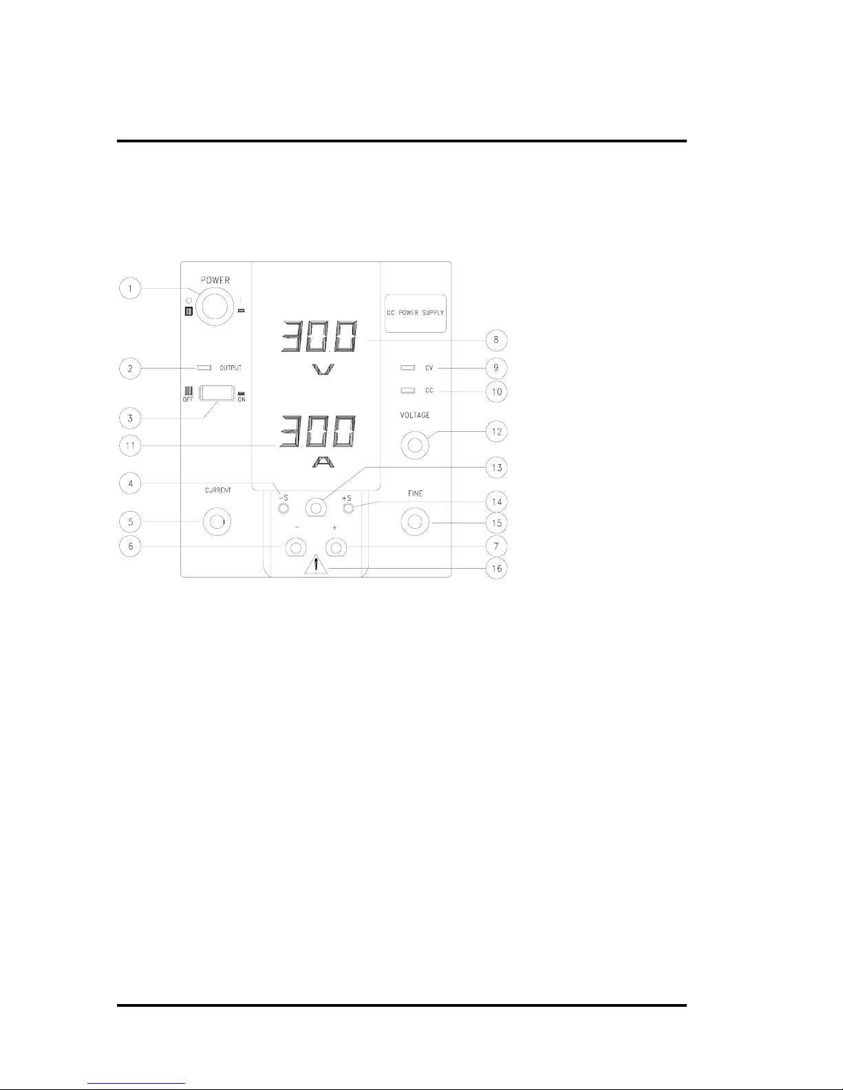
Front panel with digital
display for models
3203DR, 3302DR,
3303DR and 3601DR
2
Page 7
3000 Series
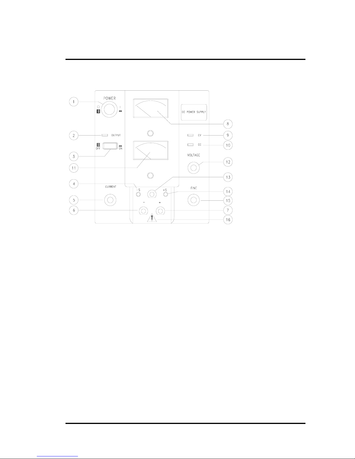
Front panel with analog
meter for models
3203AR, 3302AR,
3303AR and 3601AR
3
Page 8

3000 Series
Front panel with digital display for models 3306DR, 3603DR and 33010DR
Figure 1 Front Panels
4
Page 9

3000 Series
(1) Power Switch: Power ON/OFF switch (1=ON, 0 = OFF)
(2) Output ON/OFF LED: Red LED for indicating output ON or OFF
(3) Output ON/OFF Switch: Output ON/OFF control switch (only available in remote models)
(4) -S Remote Sensing Input Terminal: For sensing output voltage at the - load terminal (only
available in remote models)
(5) Output Current Adjustment Knob: For adjusting output current at constant current (C.C.
Mode)
(6) - Output Terminal: Negative output terminal (black)
(7) + Output Terminal: Positive output terminal (red)
(8) Voltage Indicator
a) Analog: As indicated by the pointer on the 40x40mm (Class 2.5) meter
b) Digital: Displayed in full 3-digit red 0.52" LED
(9) C.V. Mode LED: Green LED to indicate constant voltage
(10) C.C. Mode LED: Red LED to indicate constant current
(11) Current Indicator
a) Analog: As indicated by the pointer on the 40x40mm (Class 2.5) meter
b) Digital: Displayed in full 3-digit red 0.52" LED
(12) Coarse Output Voltage Adjustment Knob: For adjusting output voltage at constant voltage
(C.V. mode)
(13) GND Terminal : Ground terminal (green)
(14) +S Remote Sensing Input Terminal: For sensing output voltage at the + load terminal (only
available in remote models)
(15) Fine Output Voltage Adjustment Knob: For fine adjustment of output voltage at constant
voltage (C.V. mode)
(16) Warning Label: The bare parts of the output terminals and fittings are electrical sensing parts.
Do not touch these parts during use.
5
Page 10

2.2 Rear Panels and Bottom Panels
3000 Series
17
19
20
18
21
Rear and bottom panels for models 3203AR, 3203DR, 3302AR,
3203DR, 3303AR, 3303DR, 3601AR and 3601DR
6
Page 11

3000 Series
Rear and bottom panels for models 3306DR, 3603DR and 33010DR
Figure 2 Rear and Bottom Panels
(17) D-Type 9-pin connector (RC1) for Remote Control
(18) D-Type 9-pin connector (RC2) for Remote Control
NOTE: Items 17 and 18 are available only on the remote models. Refer to the Remote-Control
Operation Manual for details.
(19) Power Input Socket
(20) Input Power Fuse Holder and Input Voltage Selector. Acceptable input voltage ratings are
100V, 120V, 220V and 240V. The selected input voltage is set to the position above the
mark (the rear panel above shows that the input voltage is set to 100V).
(21) Remote Control Function Switches: Only available on remote models. Refer to the Remote-
Control Operation Manual for details.
7
Page 12

3000 Series
3. Operation
3.1 Pre-installation
Before you turn on the power:
• Check that the input voltage from your power source conforms to the voltage rating selected.
Refer to Input Voltage Selector in section 2.2. The tolerance is +
at 50/60 Hz.
• Place this power supply in a well-ventillated area and do not block the ventillation holes. Poor
heat dissipation leads to overheating which may cause unstable operation and shorten the
service life of this equipment.
• Be sure to use the correct fuse for your model. Refer to Table 1 for the type of fuse you
should use for a given voltage.
3.2 Setting the Output Voltage and Output Current
To set the output voltage and current, follow these steps:
10% of the indicated voltage
1. Check that the total load to be connected does not exceed the maximum output voltage and
current of this power supply.
2. Open the circuit between the + and the - output terminals. Turn the voltage adjustment knob
clockwise to the desired output voltage rating.
3. Turn the current adjustment knob counterclockwise to get the minimum value.
4. Short the circuit between the + and the - output terminals. Note that the current rating of the
shorting wire should be greater than or equal to the required current.
5. Turn the current adjustment knob clockwise until the current indicator on the front panel
displays the required current rating.
6. Remove the shorting wire from the + and the - output terminals. The power supply returns to
the constant voltage mode and is ready to use.
8
Page 13
3000 Series
3.3 Constant Voltage/Constant Current Characteristics
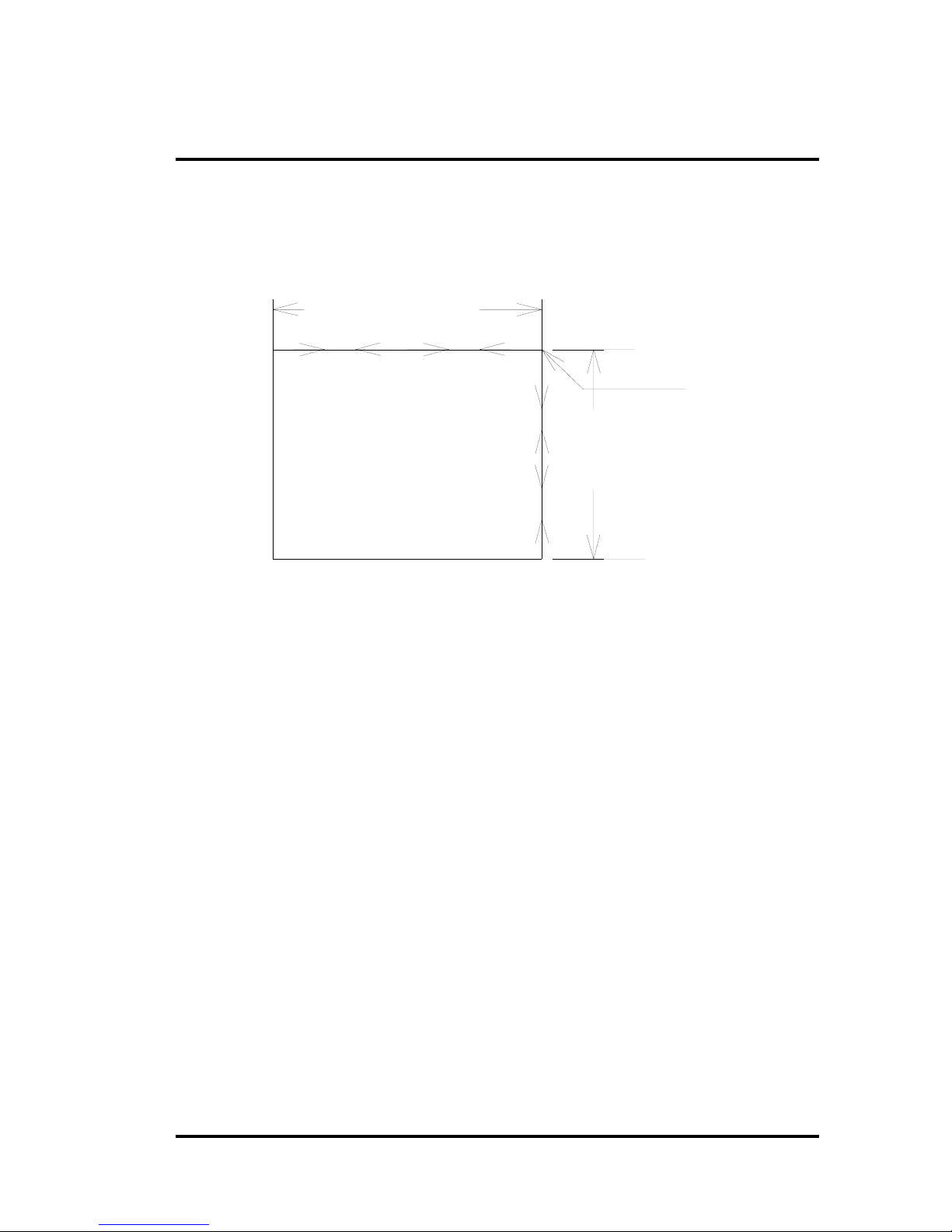
This power supply operates automatically between constant voltage (C. V. mode) and constant current
(C. C. mode) by responding quickly to rapid load changes. The following figures shows the relative
changes between the constant current and the constant voltage modes.
Constant Voltage
Crossover Point
Output
Voltage
Output Current
Figure 3 Constant Voltage vs. Constant Current Relation Diagram
Constant
Current
3.4 Operation Modes
3.4.1 Serial
Serial connection allows the connection of two or more power supplies serially to obtain a higher
voltage rating (maximum 240V for this power supply).
For serial connection, it is recommended that all power supplies operate under the constant voltage
(C.V.) mode.
Figure 4 shows the serial connection between two 3303D power supplies. One unit is set at 30V/2A
and the other at 20V/3A. Figure 5 shows the serial connection voltage/current output versus load
changes.
9
Page 14

3000 Series
2
(VO)
A
[
]
]
[
]
SET : V1 = 30V / 2A
V
V
A
+S
-
+
V
A
+S
-S-S
-
+
50
40
30
20
10
TOTAL OUTPUT VOLTAGE
V1 C.V. MODE
V1
V2
30 25 20 15 10 5
SET : V2 = 20V / 3A
V1 C.C. MODE
V2 C.V. MODE
V2 C.C. MODE
OHM
V2V1
V0=V1+V
2A
30 25 20 15 10 5
OHM
Figure 4 Serial Connection Diagram Figure 5 Serial Voltage/Current Output vs.
Load Change
3.4.2 Parallel
Parallel connection only allows thr connection of two or more power supplies of the same model to
obtain a higher current rating (maximum 24A for this power supply).
Figure 6 shows the parallel connection of two 3303D power supplies. One unit is set at 30V/3A and
the other at 20V/2.5A. Figure 7 shows the parallel connection voltage/current output versus load
changes.
SET : V1 = 30V / 3.0A
SET : V2 = 20V / 2.5A
V1&V2 C.C. MODE
V
A
+S
-S
-
+
I
V
A
+S
-S
-
+
I
2
6A
4A
2A
V
30
[V1 C.C. MODE
V2 C.V. MODE
V1&V2 C.V. MODE
86421
10
OHM
30
IO=I1+I2
-
Figure 6 Parallel Connection Diagram Figure 7 Parallel Voltage/Current Output vs.
IO
+
20
10
6421
10
OHM
30
Load Change
10
Page 15

3000 Series
NOTE: The difference between the voltage settings for two or more power supplies of the same
model connected in parallel should not exceed 15V. The minimum voltage setting should
not be lower than 10V. If it is necessary to be lower than 10V, the voltage difference
should be less than 2V. The closer to 0V the smaller the difference required.
11
Page 16

3000 Series
4. Maintenance
4.1 Changing the Fuse
The fuse is located inside the input power fuse holder (refer to Figure 2). You need to change the
fuse when:
• the fuse is blown out
• you change the voltage rating
In any case, replace the fuse with one of the same rating. Refer to Table 1 for the type of fuse used for
each model and voltage.
NOTE: Unplug the power cord before you change the fuse.
4.2 Changing the Voltage
To change the voltage, follow these steps:
1. Use a flathead screwdriver to detach the Input Power Fuse Holder and Input Voltage Selector
unit (refer to Figure 2).
2. Turn the unit so that the desired input voltage is positioned above the
4. Check that the fuse to conform to this new voltage rating. Refer to Table 1 below for the
correct fuse rating.
5. Replace the Input Power Fuse Holder and Input Voltage Selector unit.
Table 1 Power Supply Weight , Dimensions and Fuse Specification
Model Weight (Approx.) Dimension
W x H x D (mm)
Net Gross Machine Package 100V 120V 220V 240V
3203A/AR/D/DR 4.3 KG 5.5 KG 120x160x200 239x265x394 2A 2A 1A 1A
3302A/AR/D/DR 4.3 KG 5.5 KG 120x160x200 239x265x394 2A 2A 1A 1A
3303A/AR/D/DR 4.3 KG 5.5 KG 120x160x200 239x265x394 2A 2A 1A 1A
3601A/AR/D/DR 4.3 KG 5.5 KG 120x160x200 239x265x394 2A 2A 1A 1A
3306D/DR 8.6 KG 10.1 KG 230x160x324 364x265x422 4A 4A 2A 2A
3603D/DR 8.6 KG 10.1 KG 230x160x324 364x265x422 4A 4A 2A 2A
33010D/DR 13 KG 14.4 KG 230x160x366 364x265x464 8A 8A 4A 4A
Time-Delay Type 6 x 30 mm
mark.
Fuse
12
Page 17

5. Specifications
3000 Series
Model
Specification
Output Voltage 0-20V 0-30V 0-30V 0-60V 0-30V 0-60V 0-30V
Output Current 0-3A 0-2A 0-3A 0-1A 0-6A 0-3A 0-10A
CONSTANT VOLTAGE CHARACTERISTICS
Load Regulation
Line Regulation
Ripple & Noise (≦ 100W) ≦ 0.5mVrms
Ripple & Noise (≧ 100W) ≦ 1mVrms
CONSTANT CURRENT CHARACTERISTICS
Load Regulation (≦ 100W) ≦ 10mA
Load Regulation (≧ 100W) ≦ 15mA
Line Regulation
Ripple & Noise (≦ 100W) ≦ 1mArms
Ripple & Noise (≧ 100W) ≦ 3mArms
DISPLAY ACCURACY
Analog Display (A)
Digital Display (D)
PROGRAMMING SPEED
Rise Time (No Load)
(Load)
Fall Time (No Load)
(Load)
OUTPUT IMPEDANCE
RECOVERY TIME
FUNCTIONS
Series Connection
Parallel Connection
Master - Slave N/A
POWER SOURCE
ACCESSORIES ACS-002 X1
DIMENSIONS
W X H X D (mm)
3203A
3203D
± 0.01% +2mV
± 0.01% +2mV
± 0.01% +2mA
Full-scale 3%
≦ 0.1% +2d
≦ 100mS
≦ 200mS (<6A), ≦ 500mS (<10A), ≦ 1S (≧ 10A)
≦ 2.5S
≦ 250mS
< 2mΩ + 2μ H
≦ 100μ S to within 0.1% of set voltage (50% to 100% load change)
Different models can be connected in series (≦ 240V)
Same models can be connected in parallel (≦ 24 A)
ACV 100/120/220/240 ±10%, 50/60Hz
120 X 160 X 200
3302A
3302D
3303A
3303D
3601A
3601D
3306D 3603D 33010D
230 X 160 X 324 230 X 160
X 366
13
Page 18

3000 Series
Model
Specification
Output Voltage 0-20V 0-30V 0-30V 0-60V 0-30V 0-60V 0-30V
Output Current 0-3A 0-2A 0-3A 0-1A 0-6A 0-3A 0-10A
CONSTANT VOLTAGE CHARACTERISTICS
Load Regulation
Line Regulation
Ripple & Noise (≦ 100W) ≦ 1mVrms
Ripple & Noise (≧ 100W) ≦ 2mVrms
CONSTANT CURRENT CHARACTERISTICS
Load Regulation (≦ 100W) ≦ 10mA
Load Regulation (≧ 100W) ≦ 15mA
Line Regulation
Ripple & Noise (≦ 100W) ≦ 1mArms
Ripple & Noise (≧ 100W) ≦ 3mArms
DISPLAY ACCURACY
Analog Display (A)
Digital Display (D)
PROGRAMMING SPEED
Rise Time (No Load)
(Load)
Fall Time (No Load)
(Load)
OUTPUT IMPEDANCE
RECOVERY TIME
FUNCTIONS
Serial Connection
Parallel Connection
Master - Slave Yes
REMOTE CONTROL
Voltage Programmable
By External DC Voltage
By External Resistance
Current Programmable
By External DC Voltage
By External Resistance
VOLTAGE/CURRENT READBACK AVAILABLE
Voltage Readback 0 to 10V for full-scale voltage
Current Readback 0 to 0.3V for full-scale current
OUTPUT ON/OFF CONTROL YES
REMOTE SENSING Compensate voltage drop Up to 2VDC
3203AR
3203DR
± 0.01% +2mV
± 0.01% +2mV
± 0.01% +2mA
Full-scale 3%
≦ 0.1% +2d
≦ 100mS
≦ 200mS (<6A), ≦ 500mS (<10A), ≦ 1S (≧ 10A)
≦ 2.5S
≦ 250mS
<2mΩ + 2μ H
≦ 100μ S to within 0.1% of set voltage (50% to 100% load change)
Different models can be connected in series (≦ 240V)
Same models can be connected in parallel (≦ 24A)
0 to 10V, Control 0 to voltage setting
0 to 10KΩ , Control 0 to maximum voltage
0 to 10V, Control 0 to current setting
0 to 10KΩ , Control 0 to maximum current
3302AR
3302DR
3303AR
3303DR
3601AR
3601DR
3306DR 603DR 33010DR
14
Page 19

3000 Series
POWER SOURCE
ACCESSORIES ACS-002 X1, phone-jack plug X2, 9-pin D-type connector X 2
DIMENSIONS
W X H X D (mm)
ACV 100/120/220/240 ±10%, 50/60Hz
120 X 160 X 200
230 X 160 X 324
230 X 160
X 366
15
 Loading...