

Top Vision Instore PRO 9 User Manual
RECEIVER UNIT
PRO 9
User manual

P2: Safety instructions
P3: Part overview / technical specications
P4: General position of the receiver unit
P5: Chosing external or internal receiver eye (Option 1 or Option 2)
P6: Option 1: Positioning your receiver unit with an external eye on the back of a panel
P7: Option 1: Positioning your receiver unit with an external eye on the back wall.
P8: Option 1: Mounting your receiver unit with an external eye
P10: Option 2: Positioning your receiver unit with an internal eye on the back of a panel
P11: Option 2: Mounting your receiver unit with an external eye
P12: Assembling the cables
P13: Programming
P15: Warranty
P16: Contacts
.2
INDEX
SAFETY INSTRUCTIONS
IMPORTANT SAFETY INSTRUCTIONS
Before using an electrical unit, basic precautions should always be followed, including the following:
DANGER - To reduce the risk of electric shock:
1. This SECURE DISPLAY SYSTEM contains electronic components.
Do not open these without a qualied electrician or an ofcial Top Vision dealer.
WARNING - To reduce the risk of burns, re, electric shock, or injury to persons:
1. Close supervision is necessary when this unit is used by, or near children, invalids, or disabled persons.
2. Use this unit only for its intended use as described in this manual.
Do not use attachments not recommended by the manufacturer.
3. Never operate this unit if it has a damaged cord or plug, if it is not working properly,
if it has been dropped or damaged, or dropped into water.
Return the product to a service center for examination and repair.
4. Never drop or insert any object into any opening other then the intended use of presenting sunglasses.
5. Do not use outdoors / for indoor use only!
MAINTENANCE INSTRUCTIONS - Instructions for cleaning and user maintenance operations:
1. The exterior of a SECURE DISPLAY SYSTEM may only be cleaned with a non-static brush.
2. The SECURE DISPLAY SYSTEM has no user serviceable parts. All malfunctional or damaged
components are to be replaced by a service representative duly authorized by Top Vision Group BV
or an ofcial Top Vision dealer.
INTENDED USE
1. The indented use of the Secure Display System is to display eyewear frames and sunglasses.
2. This product is for commercial use only.
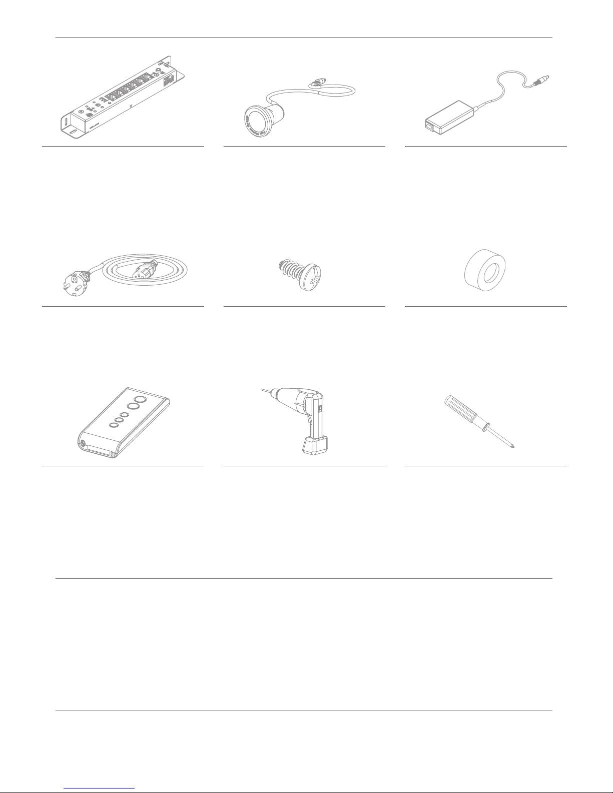
PART OVERVIEW / REQUIRED TOOLS
TECHNICAL SPECIFICATIONS ADAPTER
TECHNICAL SPECIFICATIONS RECEIVER
Product:
Art. code:
Dimensions:
Quantity:
Product:
Art. code:
Dimensions:
Quantity:
Product:
Art. code:
Dimensions:
Cable length:
Quantity:
Product:
Art. code:
Cable length:
Quantity:
Product:
Dimensions:
Product:
Art. code:
Cable length:
Quantity:
Product:
Art. code:
Dimensions:
Cable length:
Quantity:
Supply voltage:
Supply current:
Output:
Reception frequency:
Ambient temperature:
Product size:
Product weight:
Input:
Product size:
Product weight:
Temperature:
100-240 VAC
1.4A
24V
50/60Hz
-30 +60 ˚C
150x50x32mm
275 gram
24V
226x32x22mm
204 gram
5-40 ˚C
Product:
Art. code:
Dimensions:
Quantity:
Product:
Dimensions:
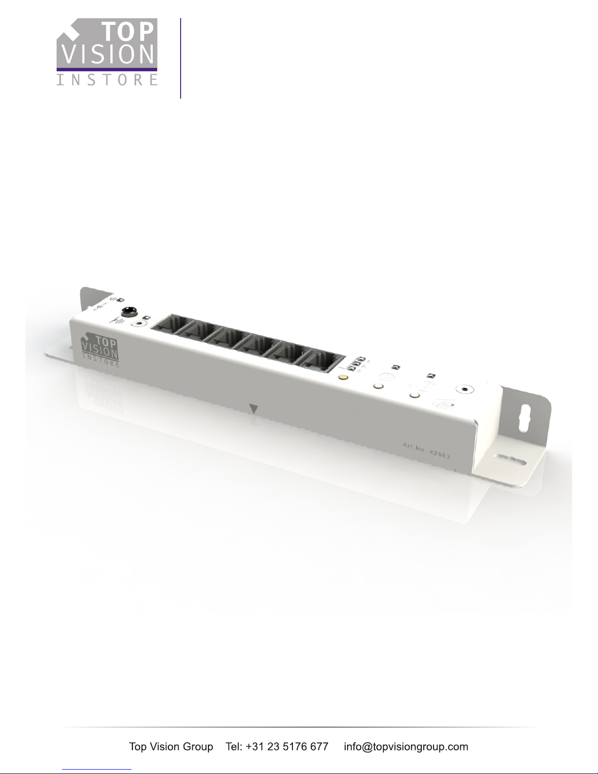
RECEIVER UNIT
50544
199x28x22mm
1x
RECEIVER EYE
22476
1450xø16mm
1x
AC-DC ADAPTER
70087
150x50x32mm
175cm
1x
SPACER
95227
25x10mm
1x
SCREWDRIVER
P1
POWER CABLE
70105
200cm
1x
REMOTE CONTROL
50498
80x35x15mm
175cm
1x
SCREW
95071
3.9x13mm
2x
DRILL
ø2.5
ø16
.3

F
A
A
B
C
D
E
F
G
H
= RJ cables
= RJ ports
= External IR receiver eye port
= External IR receiver eye
= DC in port
= AC-DC adapter
= Power plug / outlet location
= Internal IR receiver eye
NOTE EXTERNAL RECEIVER EYE
You can either use receiver eye H,
where the eye will be directly behind
the receiver unit, or the external
receiver eye D, which allows you to
place the receiver eye up to 125cm
away from the receiver unit.
E
E
B
C
H
B
D
C
G
POSITIONING OF THE RECEIVER UNIT
Please note that the distance from A (RJ cables
of the eyewear display columns) to B (RJ ports)
does not exceed 125cm.
Please note that the distance from E (DC in port)
to F (AC-DC adapter) does not exceed 170cm.
Please note that the distance from C (IR
receiver eye port) to D (IR receiver eye) does not
exceed 125cm.
Please note that the distance from E (DC port)
to G (power outlet) does not exceed 350cm.
Even before deciding where you will mount your receiver unit, please keep the following lengths of the
various cables in mind.
A TO B
E TO F
C TO D
E TO G
.4

CHOSING INTERNAL OR EXTERNAL RECEIVER EYE
Before you mounting your receiver unit, decide if you want to use the internal or external receiver eye.
You can either use the internal receiver eye H, where the eye will be directly behind the receiver unit, or the
external receiver eye D, which allows you to place the receiver eye up to 125cm away from the receiver unit.
When using the external receiver eye D, you need to drill a hole of ø16 mm,
no further then 125cm from the receiver unit.
For drilling and mounting instructions, see page 7
When using the internal receiver eye H, you need to drill a hole of ø11,5 mm,
in the center of where you will mount the receiver unit.
For drilling and mounting instructions, see page 9
OPTION 1: USING AN EXTERNAL RECEIVER EYE
OPTION 2: USING AN INTERNAL RECEIVER EYE
.5
 Loading...