

Topview Box Series, A100WIRF Series, A101B, A301B, A501B User Manual
...
1MP/3MP/5MP True Day/Night Industrial
V. 02.11
Network Box Camera
User Manual
A101B / A301B / A501B

Box Series | User Manual
Table of Content
1 Product Overview 4
1.1 Physical Characteristics 4
2 Installation and Connection 6
2.1 Package Content 6
2.2 Installation 6
2.2.1 Checking Appearance 6
2.2.2 Connecting the Wires 6
2.2.3 Mounting the camera 7
2.2.4 Network Topology 8
2.2.5 System Requirements 8
2.3 Connection 9
2.3.1 Default IP address 9
2.3.2 Connecting from a computer & Viewing Preparation 9
2.4 IP Finder 13
3 Administration and Configuration 14
3.1 Live View 14
3.2 Configuration 16
3.2.1 Information 16
3.2.2 Image Parameter 16
3.2.3 Network Settings 26
3.2.4 Account Management 31
3.2.5 Event Settings 32
3.2.6 Record Settings 35
3.2.7 System Settings 37
3.2.8 Event Log 39
Appendix A: Specification of A101B Series 40
Appendix B: Specification of A301B Series 42
Appendix C: Specification of A501B Series 44
1
Box Series | User Manual
WEEE (Waste Electrical and Electronic Equipment). Correct disposal of this product
(applicable in the European Union and other European countries with separate collection
systems). This product should be disposed of, at the end of its useful life, as per applicable
local laws, regulations, and procedures.
WARNING
This unit operates at DC 12V/ AC 24V/ PoE (IEEE 802.3af Class 0).
Installation and service should be performed only by qualified and experienced technicians and comply
with all local codes and rules to maintain your warranty.
To reduce the risk of fire or electric shock, do not expose the product to rain or moisture.
Wipe the camera with a dry soft cloth. For tough stains, slightly apply with diluted neutral detergent and
wipe with a dry soft cloth.
Do not apply benzene or thinner to the camera, which may cause the surface of unit to be melted or lens fogged.
Avoid aligning the lens to very bright objects (example, light fixtures) for long periods of time.
Avoid operating or storing the unit in the following locations:
Extremely humid, dusty, or hot/cold environments (recommended operating temperature: -10°C to +50°C)
Close to sources of powerful radio or TV transmitters
Close to fluorescent lamps or objects with reflections
Under unstable or flickering light sources
Get Started
This user manual is designed as a reference for the installation and manipulations of the unit including the
camera’s features, functions, and detailed explanation of the menu tree. Please read this manual thoroughly
and save it for future use before attempting to connect or operate the unit. The reader is supposed to be able
to get the following information in this manual.
Product Overview: the main functions and system requirements of the unit.
Installation and Connection: instructions on unit installation and wire connections.
Administration and Configuration: the main menu navigation and controls explanations.
2

Box Series | User Manual
Caution
Changes or modifications not expressly approved by the party responsible for compliance
could void the user’s authority to operate the unit.
FCC Compliance Statement
Information to the user: This unit has been tested and found to comply with the limits for a Class
B digital device pursuant to Part 15 of the FCC Rules. Operation is subject to the following two
conditions: (1) this device may not cause harmful interference, and (2) this device must accept
any interference received, including interference that may cause undesired operation. These
limits are designed to provide reasonable protection against harmful interference in a residential installation.
This unit generates, uses, and can radiate radio frequency energy and, if not installed and used in accordance
with the manual, may cause harmful interference to radio communications. However, there is no guarantee
that interference will not occur in a particular installation.
If this unit does cause harmful interference to radio or television reception, which can be determined by
turning the unit off and on, the user is encouraged to try to correct the interference by one or more of the
following measures:
Reorient or relocate the receiving antenna.
Increase the separation between the unit and receiver.
Connect the unit to an outlet on a circuit different from that to which the receiver is connected.
Consult the dealer or an experienced radio/TV technician for help.
CE Statement
Operation is subject to the following two conditions: (1) this device may not cause harmful
interference, and (2) this device must accept any interference received, including interference
that may cause undesired operation. The manufacturer declares that the unit supplied with this
guide is compliant with the essential protection requirements of EMC directive and General Product Safety
Directive GPSD conforming to requirements of standards EN55022 for emission, EN 55024 for immunity, EN
300 and EN 328 for WIFI.
3
12
2
3
15
14 5 13
Unit: ㎜
4 6 7
8 9 11
10
1
1 Product Overview
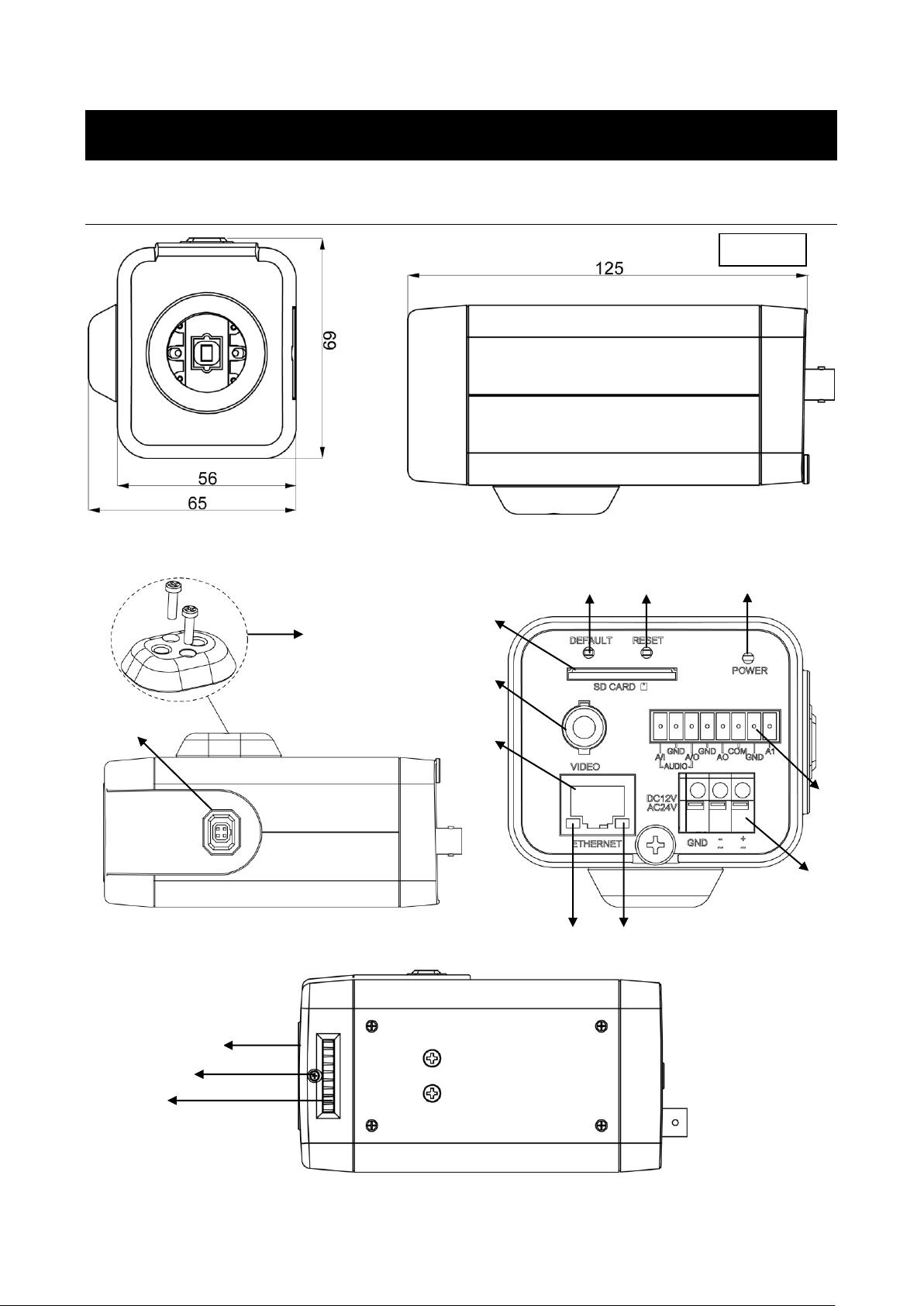
1.1 Physical Characteristics
Box Series | User Manual
Figure 1 - 1: Physical dimension & Pictorial Index
4

Box Series | User Manual
Index #
Name
Description
1
CS Mount
To connect a lens with the unit (lens sold separately)
2
Lock Screw
To lock back focus Adjustment
3
Back Focus Adjustment
To adjust focus
4
Mounting Block
The block contains 2 standard female threaded receptacles
itself and is able to connect the unit with a bracket via
standard thumbscrew.
5
Auto (DC) Iris Control
Port
When mounting a lens, connect the DC iris control line here
(lens with iris control sold separately)
6
SD Card Slot
To insert a SDHC/SDXC card into this slot for storage
7
BNC Video Outlet
To output video signal
8
RJ-45 Ethernet
Connector/ PoE
To insert the RJ-45 cable for network connection as well as
PoE (Power over Ethernet) capability
9
Default Button
To restore all settings of the unit to the factory defaults by
pressing for 5 seconds
10
Reset Button
To reboot the unit
11
Power Indicator
To indicate power status with red light
12
I/O Connector
To connect Input/ Output devices via the 8-pin removable
terminal block (supplied)
13
Power Terminal
DC12V/AC24V, red port: power +/white port: power –/ black
port: GND. Make sure to connect the power connector to
correct ports (+ and –) when the power supply is DC12V.
14
Ethernet Link LED
Solid green light stands for a live connection is established
15
Ethernet Activity LED
Amber flashing indicates data is being transmitted / received
by the unit
A/I
Audio in
GND
A/O
Audio out
GND
AO
Alarm out
COM
A1
Alarm in
GND
Note
Power supply terminal/adaptor for IO connectors and field wiring should comply with the Class
2 Circuit standard for ensuring safe from electrical fires and providing acceptable protection
against electrical shock.
Table 1 - 1: Pictorial Index Definition
Table 1 - 2: I/O Connector Definition
5

Box Series | User Manual
Caution
If using DC supply, make sure the polarity is correct. Incorrect connection may cause
malfunction and/or damage to the unit.
2 Installation and Connection
2.1 Package Content
Check everything in the packing box matches to the order form and the packing slip. In addition to this manual,
items below are included in the packing box.
One unit of network Box Camera
One 8-pin terminal block for alarm input/output
One CD containing the IP Finder, user manual, and quick installation guide
One printed quick installation guide
Please contact your dealer if any item missing.
2.2 Installation
Following tools might help you complete the installation:
a drill
screwdrivers
wire cutters
2.2.1 Checking Appearance
When first unboxing, please check whether if there is any visible damage to appearance of the unit and its
accessories. The protective materials used for the packaging should be able to protect the unit from most of
accidents during transportation.
Please remove the protective film of the unit when every item is checked in accordance with the list in “2.1
Package Content”
2.2.2 Connecting the Wires
Connect the power cable to the power plugs with one of the following options.
DC 12V: Connect 12V (-) to terminal =DC 12V-, and Connect 12V (+) to terminal =DC 12V+
AC 24V: Connect 24V (~) cables to terminals ~AC 24V
PoE (IEEE 802.3af Class 0): Connect the RJ-45 jack to a PoE compatible network device that
supplied power with networking capability through the Ethernet cable.
Insert audio cable and alarm cable to the corresponding connectors of the unit if required.
6

Box Series | User Manual
Note
To prevent the unit from falling off, ensure that it is mounted to a firm place (ceiling slab or
channel) using a safety wire strong enough to withstand the total weight of the unit. (Pay also
attention to the finishing at the end of the wire.) By cabling so, it is possible to prevent the unit
from accidental falling suddenly at any time.
Safety wire (fall prevention wire, not supplied)
Safety-cord screw of the unit
2.2.3 Mounting the camera
Please insert the screws into the mounting block and either top or bottom holes of the unit. Securely
fasten the screws to ensure the mounting block is connected with the unit tightly. Select a bracket (sold
separately) which has a standard thumbscrew matching the threaded receptacles of the mounting block
and tighten them. Depending on different applications, mount your selected bracket onto wall/celling to
complete mounting procedure.
Connect the Safety Wire (Fall Prevention Wire, not supplied) with one end to the wall/ceiling and the
other end to the safety-cord screw of the unit.
Figure 2 - 1: Mounting the Camera
7
Box Series | User Manual
System Hardware
CPU
Intel Pentium 4 2.4GHz or equivalent
RAM
1 GB or above
Display
NVIDIA GeForce 6 Series or ATI Mobility Radeon 9500
System Software
Operating System
Microsoft Windows XP, Windows Vista, Windows 7 or above
Browser
Microsoft Internet Explorer 8 - 10711, Chrome, Firefox
Unit
Power Supply
DC 12V / AC 24V / PoE (IEEE 802.3af Class 0)
Networking
Wired*
10/100BASE-T Ethernet (RJ-45 connector)
Note
All the installation and operations should comply with your local electricity safety rules.
Caution
To avoid damage to the unit, never connect more than one type of power supply (PoE (IEEE
802.3af Class 0) or DC 12V/ AC24V power plug) at the same time. If using PoE, this camera is
to be connecting only to PoE networks without routing to heterogeneous devices.
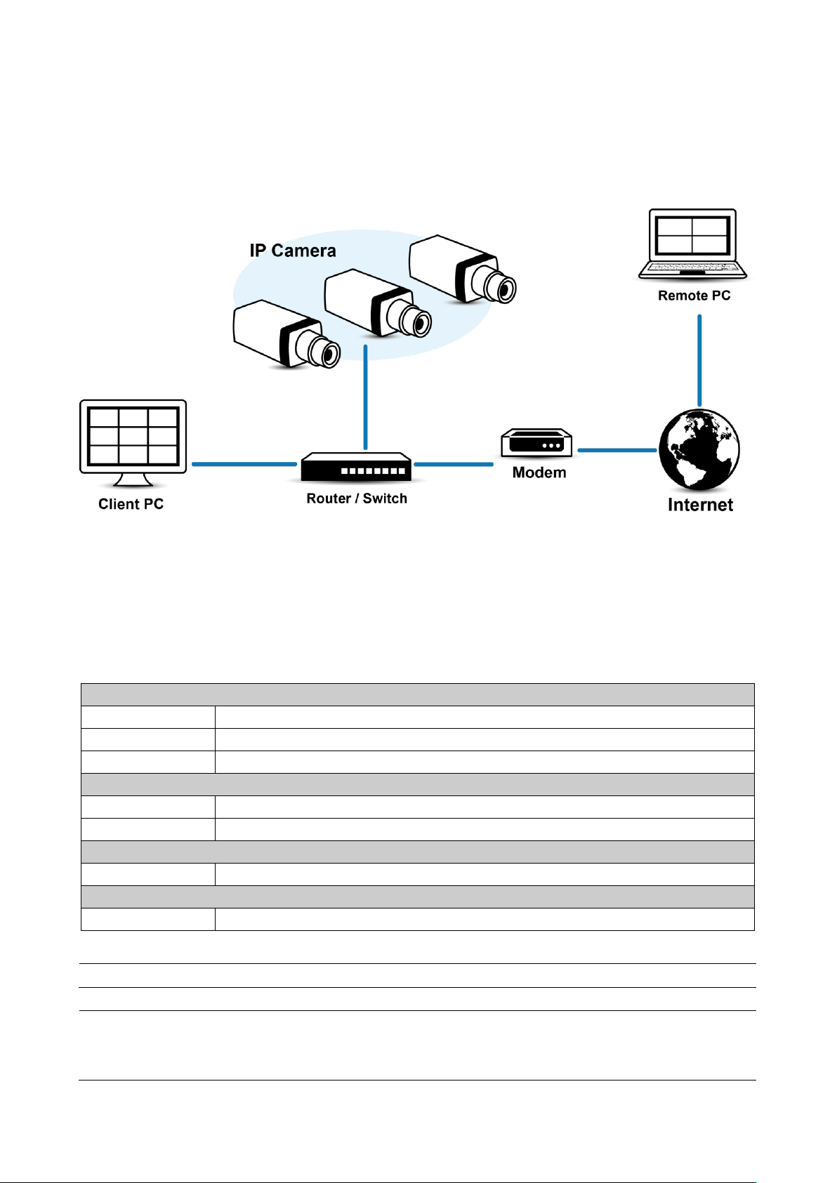
2.2.4 Network Topology
The unit, which is equipped with Ethernet RJ-45 network interface, can deliver video images and audio in real
time via either Internet or Intranet. Please refer to the skeleton drawing shown below for understanding.
Figure 2 - 2: Network Topology
2.2.5 System Requirements
Below table lists the minimum requirement to implement and operate the unit. No hardware/software
component inferior to the requirements is recommended.
Table 2 - 1: System Requirements
*a switch is required for surveillance on multiple units.
8
Box Series | User Manual
2.3 Connection
2.3.1 Default IP address
Since this is a network-based unit, an IP address must be assigned at the very first. The unit’s default IP
address is 192.168.0.30 and sub mask is 255.255.255.0. However, if you have a DHCP server in your
network, the unit would obtain an IP address automatically from the DHCP server so that you don’t need to
change the camera’s IP address. But be sure to enable DHCP in "Network Settings".
2.3.2 Connecting from a computer & Viewing Preparation
Connecting from a computer
1. Make sure the unit and your computer are in the same subnet.
2. Check whether if the networking available between the unit and the computer by executing ping the
default IP address. To do this, simply start a command prompt (Windows: from the Start Menu, select
Program. Then select Accessories and choose Command Prompt.), and type “Ping 192.168.0.30”. If the
message “Reply from…” appears, it means the connection is available.
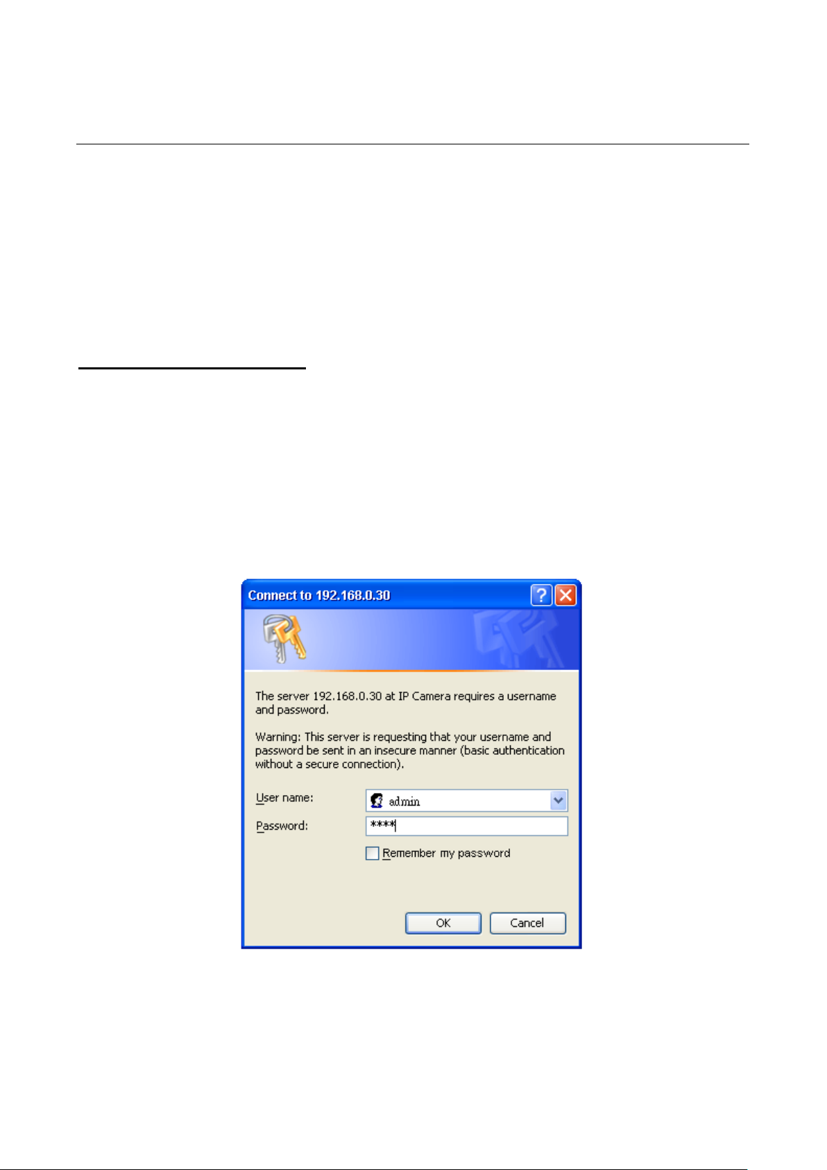
3. Start a browser e.g. Internet Explorer and enter IP address: 192.168.0.30. A login window should pop up.
In the window, enter the default user name: admin and password: 1234 to log in.
Further administration on the unit can be found in “3. Administration and Configuration".
Figure 2 - 3: Login Window
9

Box Series | User Manual
Viewing Preparation
Images of the unit can be viewed through various browsers. Before viewing, follow these steps to enable the
display.
1. Enable Cookies as instructions below
In Internet Explorer, click Internet Options on the Tools menu.
On the Privacy tab, move the settings slider to Low or Accept All Cookies.
Click OK.
2. When a proxy server is used, click Internet Options on the Tools menus of Internet Explorer, select
Connect tab, click LAN button, and set proxy server.
3. Change Security in Internet options as instructions below
On tool menu, click Internet Options.
Press the Security tab.
If the camera operates inside of the intranet, click the Intranet icon.
If the camera operates outside of the intranet, click the Internet icon.
Click Custom Level. This will open the Security Settings – Internet Zone screen.
Figure 2 - 4: Security Settings 1/4
10
Box Series | User Manual
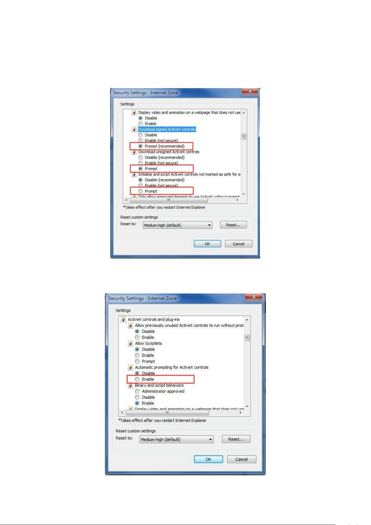
Scroll down to the ActiveX controls and plug-ins radio buttons and set as follows:
【Download signed ActiveX controls】 Prompt (recommended)
【Download unsigned ActiveX controls】 Prompt
【Initialize and script ActiveX not marked as safe for scripting】 Prompt
Figure 2 - 5: Security Settings 2/4
【Automatic prompting for ActiveX controls】 Enable
Figure 2 - 6: Security Settings 3/4
11
Box Series | User Manual
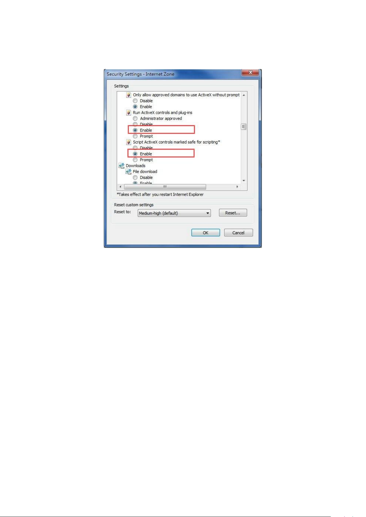
【Run ActiveX controls and plug-ins】 Enable
【Script ActiveX controls marked safe for scripting*】 Enable
Figure 2 - 7: Security Settings 4/4
Press OK to save the settings.
Close all your browser windows and restart a new window. This will allow the new settings taking
effect.
Type your setting IP address into the browser.
Then you should be able to see the camera image screen.
12

Box Series | User Manual
2.4 IP Finder
IP Finder is a utility program that helps users to locate the unit in local area network that computer is
connected to. Please note that IP Finder works only in Microsoft Windows XP, Microsoft Windows Vista,
Microsoft Windows 7 or above. Steps to get the utility program running are listed below.
1. Insert the CD-ROM in the optical drive.
2. Copy the IP Finder’s folder on the CD-ROM to computer.
3. Double click on IPFinder.exe in computer’s IP Finder folder, and the IP Finder window should pop out.
4. The window would list information of units in operation at present. Press FIND CAMERA to find more units.
5. Locate and double-click one of the cameras in the list you want to configure the network settings. If you
have multiple cameras connected to your local network, locate the MAC address on the camera to
distinguish the target camera from others.
6. Configure the following settings as needed.
NAME: Enter a descriptive name for the camera.
NETWORK SETTINGS: If you have a DHCP server on your network to assign IP addresses to
network devices, enable the DHCP option. Otherwise, manually enter the IP ADDRESS, NET MASK
and GATEWAY values.
USERNAME & PASSWORD: Manually setup preferred username and password.
SET: Whenever you make revision of camera settings, click “SET” to take effect.
SW DEFAULT: To perform the factory defaults excluding network settings of the selected camera.
HW DEFAULT: To perform the factory defaults of the selected camera.
RESET: To reboot the selected camera.
Click Save to enable the settings and click Exit to exit the utility.
Figure 2 - 8: IP Camera Finder
13
 Loading...