


FemtoFiber smart
Ultrafast
Fiber Laser
Manual
Manual: M-056 Version 08
Copyright
2018 TOPTICA Photonics AG
TOPTICA Photonics AG
Lochhamer Schlag 19
D-82166 Graefelfing/Munich
Tel.: +49 89 85837-0
Fax: +49 89 85837-200
email: info@toptica.com
http://www.toptica.com
(September 2018 Subject to change without notice)

Dear Customer,
FemtoFiber smart Manual
Welcome to the T
OPTICA community!
We have designed this product to be easy to use and reliable so that you can focus on your work. If you
have questions or need advice on how to integrate it into your setup, please contact us immediately so
we can walk you through the process. We will provide you with quick and competent help through our
service staff and product managers.
You can contact us in the following ways:
- Internet: service.toptica.com. In our support section you can find a list of frequently asked questions and a service contact form
- Email: service@toptica.com
- Phone: +49-89-85837-150
Our customers in the USA and Canada may contact T
OPTICA Photonics Inc.:
- Phone: +1-585-657-6663
Our customers in Japan may contact T
OPTICA Photonics K.K.:
- Phone: +81-42-306-9906
Please have your product ID and serial number ready when contacting us-so we can quickly retrieve all
relevant information.
As we are constantly improving our products, we greatly value all customer feedback. We encourage
you to tell us what you like about our products as well as any suggestions for improvement.
Best regards,
Harald Ellmann
Director Service
T
OPTICA Photonics AG
Statu s: 6.9.18

FemtoFiber smart Manual
Contents
1 General Description of the FemtoFiber smart System 3
1.1 Ytterbium Fiber Lasers 3
1.2 Erbium Fiber Lasers 4
1.3 FemtoFiber smart Switch Box (Optional) 5
1.3.1 USB-Control 5
2 Safety Instructions and Warnings 6
2.1 General Safety Terms 6
2.2 Safety Labels 8
2.2.1 Laser Beam 8
2.2.2 Apertures 8
2.2.3 CFR Compliance 9
2.3 Identification of Manufacturer 9
2.4 Safety Features 10
2.4.1 External Interlock 10
2.4.2 Shutter (Free Beam Version) 10
2.4.3 Protection Cap on Fiber Pigtail or FC/APC Connector 10
3 Installation 11
3.1 Package Contents 11
3.2 Installation Instructions 12
4Operation 13
4.1 Operator Controls FemtoFiber smart Laser 13
4.2 Operator Controls FemtoFiber smart Switch Box 15
4.3 FemtoFiber smart System Quickstart 18
4.3.1 OEM Integrated Environment 18
4.3.2 Manual Operation via Switch Box 19
4.3.3 FemtoFiber smart Operation via Software Commands 20
4.3.4 FemtoFiber smart Operation with Graphical User Interface 23
4.3.5 System Requirements 23
5 TOPAS FemtoFiber smart Control Software 27
5.1 Upper and Lower Screen Section 27
5.1.1 Header 27
5.1.2 Footer 27
5.1.3 Menu 28
5.1.4 Help 31
5.2 Control Section 32
5.2.1 System Info Tab 33
5.2.2 Micro Mover Tab (only FYb Systems) 34
Status: 6.9.18

6Appendix 35
6.1 Specifications 35
6.2 Pin Assignment D-Sub 9 Input/Output Connector 35
6.3 Operation without Switch Box (Control via TTL/Analog Pins) 36
6.4 Pin Assignment of Laser On Input Connector (Switch Box) 37
6.5 Pin Assignment of Power Supply Connector (Switch Box) 37
6.6 Firmware Update 38
6.7 USB Connection (Installation of FTDI CDM Drivers) 39
6.8 Precautions for Non-Condensing Operation Conditions 41
6.9 Declaration of CE Conformity 42
6.10 Main Dimensions of the FemtoFiber smart System Versions 43
6.10.1 FemtoFErb Free Beam 43
6.10.2 FemtoFErb with Fiber Pigtail 44
6.10.3 FemtoFErb with FC/APC Fiber Connector 45
6.10.4 Femto/PicoFYb with Fiber Pigtail 46
6.11 License and Copyright Information associated with Third Party Software 47
6.12 EU Legislation for Electrical and Electronic Equipment (EEE) 47
7 Guarantee and Service 48
Status: 6.9.18

FemtoFiber smart Manual
1 General Description of the FemtoFiber smart System
Ultrafast fiber lasers provide an ideal combination of system parameters: Small form factor at low cost,
but on the other hand reliable and having brilliant laser performance. Various bulky and cost-consuming
solid-state laser concepts are therefore getting more and more replaced by robust and reliable turnkey
fiber lasers.
T
OPTICA´s FemtoFiber smart lasers are the most compact and cost-effective laser sources for Terahertz
generation. Other applications benefiting from the FemtoFiber smart laser solutions are e.g. metrology
systems, light sources for microscopy, ophthalmology or medical surgery/ examination.
The FemtoFiber smart laser systems are based on rare earth doped fibers and saturable absorber mirror (SAM) mode-locking technology. Generally, the fiber technology ensures a very compact design and
highest robustness against vibration or mechanical shocks. The use of mass produced fiber components
with the proof of Telcordia standards provides an unique cost-benefit ratio. The passive SAM device
ensures self-starting and reliable mode-locking.
Key Features for all systems of the FemtoFiber smart family:
•Turnkey
•Compact
• State of the art FemtoFiber technology: robust and reliable all- fiber setup
• Fiber coupled output
• All necessary control electronics inside
• Telcordia proved components
NOTE ! Please refer to the website www.toptica.com for detailed specifications of the FemtoFiber
smart.
For individual laser system specifications, please refer to the Production and Quality Control Data Sheet.
The FemtoFiber smart lasers are plug & play systems for both OEM integrators and single unit customers.
They provide an electrical interface for remote control and only need 12 ± 2 V DC filtered supply input for
all internal electronics. For single system users the supplied Switch Box provides all switches, supply and
status lines to run a FemtoFiber smart as a stand-alone system without integration environment.
Alternatively, FemtoFiber smart laser heads can also be controlled via an USB-interface.
1.1 Ytterbium Fiber Lasers
PicoFYb 1030/1064
The PicoFYb laser systems are fiber-based picosecond oscillators for seeding industrial laser systems, e.g.
for micro-machining. The PicoFYb laser pulses with excellent amplitude and frequency jitter parameters
are amplified to typical multi-Watt levels in the MOPA (master oscillator, power amplifier) laser or regenerative amplifier systems of our customers. Typical amplifiers are slab, rod and disc lasers operating in the
1 µm wavelength regions.
FemtoFYb 1030
The FemtoFYb laser systems are fiber-based sub-picosecond to femtosecond oscillators for seeding
industrial laser systems, e.g. for micro-machining. The FemtoFYb laser pulses with excellent amplitude and
frequency jitter parameters are amplified to typical multi-Watt levels in the MOPA (master oscillator,
power amplifier) laser or regenerative amplifier systems of our customers. Typical amplifiers are slab, rod
and disc lasers operating in the 1 µm wavelength regions.
Page 3
Statu s: 6.9.18

FemtoFiber smart Manual 1. General Description of the FemtoFiber smart System
1.2 Erbium Fiber Lasers
FemtoFErb 1560
The FemtoFErb 1560 is a very robust all fiber-based femtosecond laser system with excellent amplitude
and frequency jitter parameters. Applications benefiting from the most stable, compact and cost-effective FemtoFErb 1560 are e.g. Terahertz or metrology systems, light sources for microscopy, ophthalmology
or medical surgery/examination.
FemtoFErb 1560 FD6.5
The FemtoFErb 1560 FD6.5 is the fiber delivery version of the FemtoFErb 1560 providing a 6.5 m external
SM PM 1560 fiber and transform-limited pulses at the fiber end. This allows replacing complex beam delivery setups by flexible and convenient fiber solutions. Applications benefiting from the most stable, compact and cost-effective FemtoFErb FD6.5 are e.g. Time-Domain Terahertz, medical applications like
endoscopy or metrology systems.
FemtoFErb 1560 and FemtoFErb 1560 FD6.5 with THz Option
This option includes a special technology called QuTE (Qu
connected permanently and directly to the THz antennas. This option prevents possible Q-switch pulses
to reach the antennas, which may occur at the laser start-up procedure.
FemtoFErb 780
The FemtoFErb 780 is a very compact all fiber-based femtosecond laser system with integrated miniaturized second-harmonic generation unit. It unites both supply electronics and laser unit in one box, being
thus one of the smallest fiber laser units on the market. The system only needs 12 ± 2 V DC filtered power
supply and comprises a free-beam output with mechanical shutter.
FemtoFErb 1950
The FemtoFErb 1950 laser is a very robust all fiber-based femtosecond laser system with excellent amplitude and frequency jitter parameters. A frequency shifted solitonic pulse is generated by nonlinear
effects. The unit is used for seeding Thulium doped amplifiers and also for other purposes in the 2 µm
wavelength range
-Switch Termination) allowing the laser to be
Page 4
Statu s: 6.9.18

FemtoFiber smart Manual 1. General Description of the FemtoFiber smart System
1.3 FemtoFiber smart Switch Box (Optional)
The FemtoFiber smart Switch Box is a small tool which provides all switches as well as supply and status
lines necessary to run a FemtoFiber smart laser as a stand-alone system without integration environment
and therefore is recommended especially for single-system users.
Figure 1 FemtoFiber smart Switch Box
NOTE ! All FemtoFiber smart lasers are principally designed for OEM integration.
For stand-alone operation of a FemtoFiber smart: In order to achieve full accordance with
general and nation-specific laser safety regulations (IEC 60825, CDRH, etc.), it is necessary
to supply a FemtoFiber smart laser with a Switch Box at all time !
1.3.1 USB-Control
All FemtoFiber smart laser heads are equipped with a serial USB interface for remote control of the laser
and to integrate it into software environments.
In order to establish an USB connection a USB cable (max. 2 meters length) and a suitable computer
with a free USB 2.0 port are needed. For further details of the USB-Control please refer to section 4.3.3.
NOTE ! A FemtoFiber smart laser system operated without Switch Box, but instead with 12 V direct
power supply and USB remote control, is officially not approved by T
applications. This combination would circumvent the general laser safety regulations (no
interlock mechanism, no lockable power key-switch etc.). T
such setups.
This note is not valid for OEM integrators.
OPTICA waives all liabilities for
OPTICA for stand-alone
Page 5
Statu s: 6.9.18
FemtoFiber smart Manual 2. Safety Instructions and Warnings
2 Safety Instructions and Warnings
The following Safety Instructions and Warnings should be read and complied with during operation or
maintenance of FemtoFiber smart. Failure to do so could result in damage to FemtoFiber smart or/and
personal injury or death.
2.1 General Safety Terms
FemtoFiber smart is manufactured according to the Laser Safety Standard EN 60825-1:2014 and complies
with US law 21 CFR §1040.10 and §1040.11.
The following safety terms are used in this manual:
The DANGER ! heading in this manual explains hazards that could result in personal injury or death.
The CAUTION ! heading in this manual explains hazards that could damage the instrument.
In addition, a NOTE ! heading gives information to the user that may be beneficial when using the
device.
DANGER ! Before operating the FemtoFiber smart please read this manual carefully to prevent personal
CAUTION ! injury and damage to the device. The following safety instructions must be followed at all
times.
DANGER ! Possibility of electrical shock ! Wherever this symbol is attached, the possibility of an
CAUTION ! electrical shock may appear. Use only equipment and accessories supplied
by T
OPTICA.
Caution ! Wherever this symbol is attached read and understand the manual before
operating the device. The manual must be consulted in order to find out the nature
of the potential HAZARDS and any actions which have to be taken to avoid them.
DANGER ! OEM use of the FemtoFiber smart Laser Source (integration into an end device, operation
CAUTION ! without Switch Box): The operator or designer of the end device is responsible for integration
of a key switch and an interlock circuit to the 12 ± 2 V DC Supply as well as to install redundant laser emission warning lamps, a shutter and to apply the according laser safety labeling
according to the Laser Safety Standard EN 60825-1:2014.
DANGER ! The Laser Driver Electronics (Switch Box) and the Laser Head are both equipped with LEDs
CAUTION ! that indicate laser emission. (Please refer to sections 4.1 and 4.2 in this manual for detailed
information).
Be aware of laser emission when at least one of these LEDs lights up.
Page 6
Statu s: 6.9.18

FemtoFiber smart Manual 2. Safety Instructions and Warnings
DANGER ! During installation, maintenance and service, all persons in the room must wear appropriate
laser safety goggles while the laser is in operation. The recommended protection stage is
dependent on the laser system.
Use appropriate eyewear and other protective means in order to keep radiation exposure
below the maximum permissible levels allowed by applicable regulations (examples: OSHA
limits in the US, BGV B2, BGI5092, TROS Laserstrahlung in Germany).
To determine the protection level of the laser safety goggles required for e.g. FemtoFErb 780
laser system, please refer to the following example: FemtoFErb 780 with collimated beam,
beam diameter 1.6 mm, wavelength = 780 nm, repetition rate 100 MHz, laser power up to 6070 mW generates a peak power density of H
BGI5092 this leads to a required protection level of 780 D LB 4 + M LB 1 for your eyewear.
DANGER ! Laser safety goggles selected for adjustment purposes do not protect against an intention-
ally focused direct beam which will increase the optical power densities by a few orders of
magnitude.
DANGER ! Regular functional checks and performance inspections at the supplier are recommended
for all laser safety goggles.
DANGER ! Do not position the equipment so that it is difficult to operate the disconnecting device.
DANGER ! Use of controls or adjustments or performance of procedures other than those specified
herein may result in hazardous radiation exposure.
~ 0.3 mJ/m² (approximately). From Table 3 in
M
DANGER ! If the equipment is used in a manner not specified by the manufacturer, the protection pro-
vided by the equipment may be impaired.
DANGER ! The FemtoFiber smart uses very powerful lasers (up to class 3B). Therefore, it is imperative to
take great care and observe the statutory warning labels on the unit.
DANGER ! Do not open the device at any time, FemtoFiber smart is a hands-off laser system. Reflections
of the laser beam may cause serious injury to your eyes. Internal tuning as well as the replacing of components may only be carried out by T
OPTICA. Under certain circumstances there
may be dangerous voltages, even if the device is disconnected from the mains supply.
DANGER ! Do not look into the beam from the Laser Output (depending on the version: free beam, FC/
APC connector(s) on front panel or FC/APC connector at the fiber pigtail) as the output can
exceed the limits for class 1 specified by US laws 21 CFR 1040.10 and 2 CFR 1040.11 and the
Laser Safety Standard EN 60825-1:2014. Take precautions to eliminate exposure to a direct or
reflected beam.
DANGER ! FemtoFiber smart may not be operated in surroundings of flammable gases or fumes.
CAUTION ! Special precautions are necessary if FemtoFiber smart is to be operated in surroundings of
high electro-magnetic radiation such as close to a plasma discharge. Please refer to T
OPTICA
for technical support.
CAUTION ! Since the FemtoFiber smart has power levels which may already destroy optical fibers, please
pay special attention to a clean fiber facet at the output fiber connector. We also recommend to always switch-off the laser emission before the fiber connector is opened/closed!
CAUTION ! FemtoFErb 1560 standard version: While starting the laser it may occur that higher level pulses
are sent out by the laser. This transient phenomenon is due to the fact that the amplifier of
the system starts simultaneously with the oscillator. We therefore recommend blocking the
output beam at the moment when the laser is switched on, or adding the THz option.
Page 7
Statu s: 6.9.18
FemtoFiber smart Manual 2. Safety Instructions and Warnings
2.2 Safety Labels
2.2.1 Laser Beam
FemtoFiber smart emits invisible pulsed laser radiation of up to 170 mW power. It is classified as Class 3B
product.
DANGER ! FemtoFiber smart emits invisible pulsed laser radiation of up to 170 mW power (Class 3 B
laser product). Avoid exposing eyes and skin to the laser beam, including any laser stray
light !
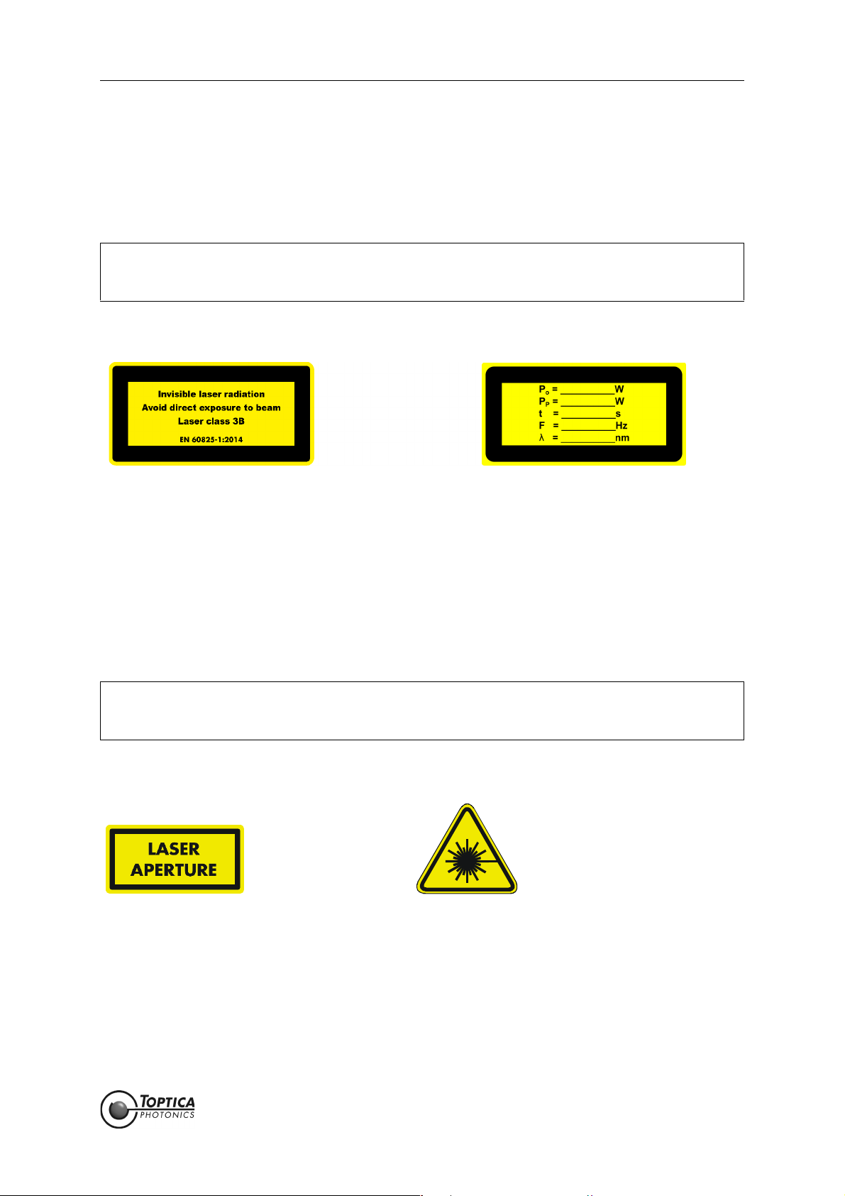
The following labels are affixed to the outer side of the FemtoFiber smart laser protective housing according to EN 60825-1:2014:
Size: 52 mm x 26 mm
Color: yellow/black
Location: Outer side of the FemtoFiber smart laser protective housing
2.2.2 Apertures
During operation, depending on the individual system, the laser beam is emitted at the laser beam aperture(s), either free beam, from the FC/APC fiber connector at the front panel or from the fiber pigtail.
DANGER ! FemtoFiber smart emits invisible pulsed laser radiation of up to 170 mW power (Class 3B
laser product). Avoid exposing eyes and skin to the laser beam, including any laser stray
light !
The following labels are affixed to the outer side of the FemtoFiber smart laser protective housing next to
the laser beam aperture(s) according to EN 60825-1:2014:
Size: 26 mm x 13 mm Size: 15 mm x 15 mm
Color: Yellow/black Color: Yellow/black
Location: Besides laser beam aperture(s) Location: FemtoFiber smart laser protective
housing
Page 8
Statu s: 6.9.18
FemtoFiber smart Manual 2. Safety Instructions and Warnings
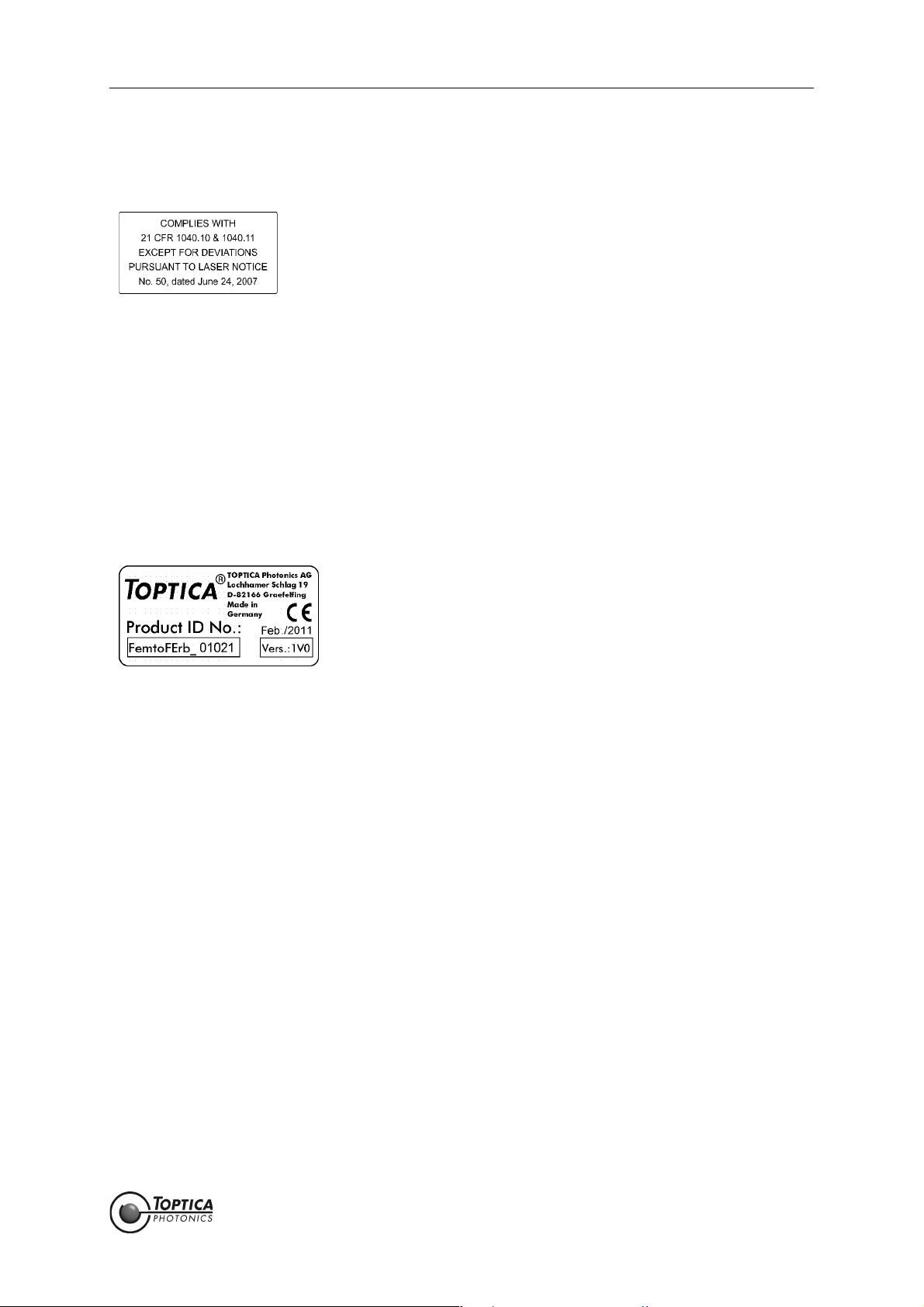
2.2.3 CFR Compliance
Compliance with US laws 21 CFR §1040.10 and §1040.11 is declared by the following label:
Size: 38 mm x 19 mm
Color: silver/black
Location: FemtoFiber smart Laser Head
housing
2.3 Identification of Manufacturer
Manufacturer (name and address), production date, FemtoFiber smart model, serial number, article
number and compliance with CE standards are noted on the identification label:
Size: 38 mm x 19 mm
Color: Silver/black
Location: Outer side of the FemtoFiber smart laser protective housing
Page 9
Statu s: 6.9.18
FemtoFiber smart Manual 2. Safety Instructions and Warnings
2.4 Safety Features
2.4.1 External Interlock
An interlock circuit to connect e.g. a door switch can be set up by using the Interlock Connector on the
Switch Box (for location please refer to Section 4.2). For first operation, a bridged interlock plug is supplied
to close the interlock circuit. For safety reasons the installation of an external interlock circuit is strongly
recommended.
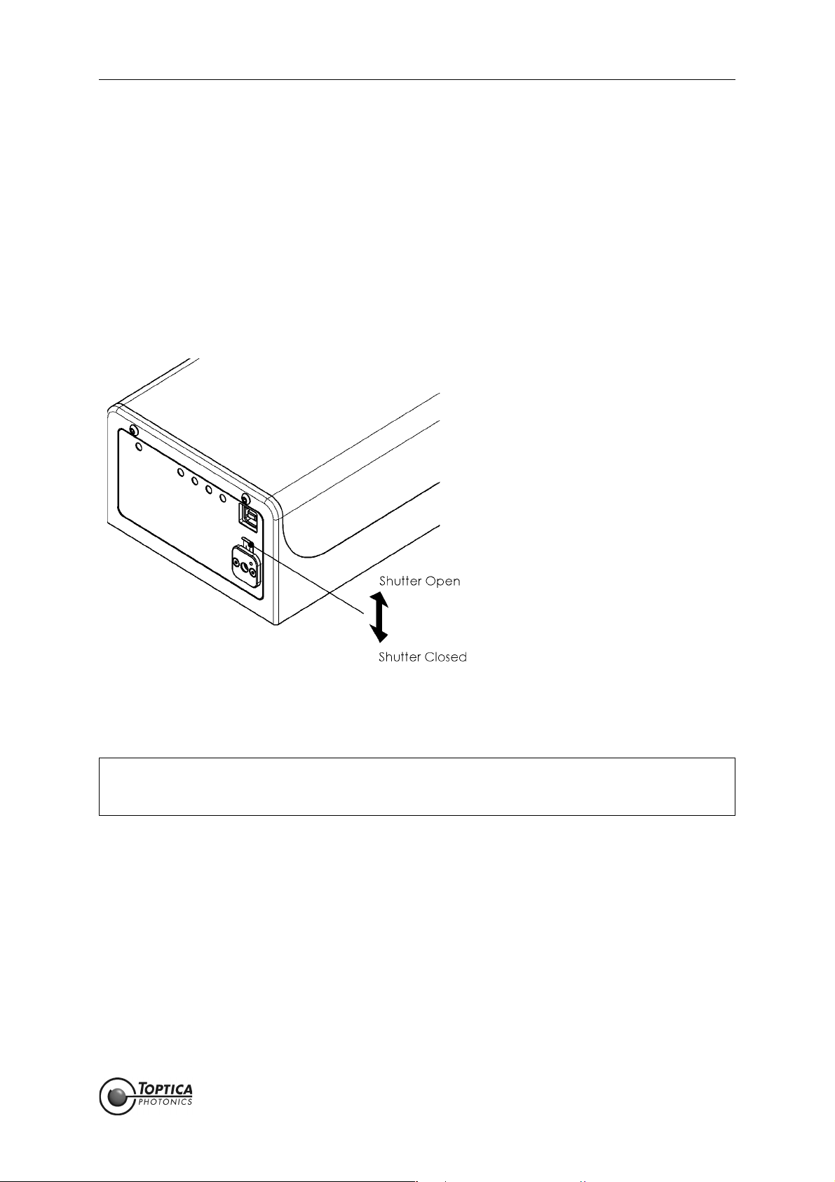
2.4.2 Shutter (Free Beam Version)
Figure 2 FemtoFiber smart shutter operation (only free beam version)
Shift shutter lever up/down as shown in Figure 2 to open/close the laser beam shutter.
NOTE ! When the emission of the FemtoFiber smart laser is switched on with closed shutter, back
reflections from the shutter may disturb the internal photo diode/power regulation. This
may lead to unexpected error messages, but is not harmful to the laser.
2.4.3 Protection Cap on Fiber Pigtail or FC/APC Connector
Due to transport and laser safety, depending on the specification the end of the fiber pigtail at the
FemtoFiber smart or the FC/APC connector is protected by a cap. It must be removed before the first
usage of the laser module.
Page 10
Statu s: 6.9.18

FemtoFiber smart Manual 3. Installation
3 Installation
3.1 Package Contents
Depending on the order, the complete FemtoFiber smart System consists of the following parts:
1 FemtoFiber smart Laser
1 FemtoFiber smart Manual (optional)
1 Production and Quality Control Data Sheet
when ordered with Switch Box (optional):
1Switch Box
1 D-Sub 9 Cable (Switch Box/FemtoFiber smart Laser)
1 FemtoFiber smart Power Supply with mains cable
when ordered wit F
1F
only FemtoFErb 1560 FD6.5
1 Single Mode PM 1560 Fiber with FC/APC connectors on both sides (optional)
IBEROUT FemtoFiber smart IR Fiber Collimator (optional)
IBEROUT option:
Page 11
Statu s: 6.9.18
FemtoFiber smart Manual 3. Installation
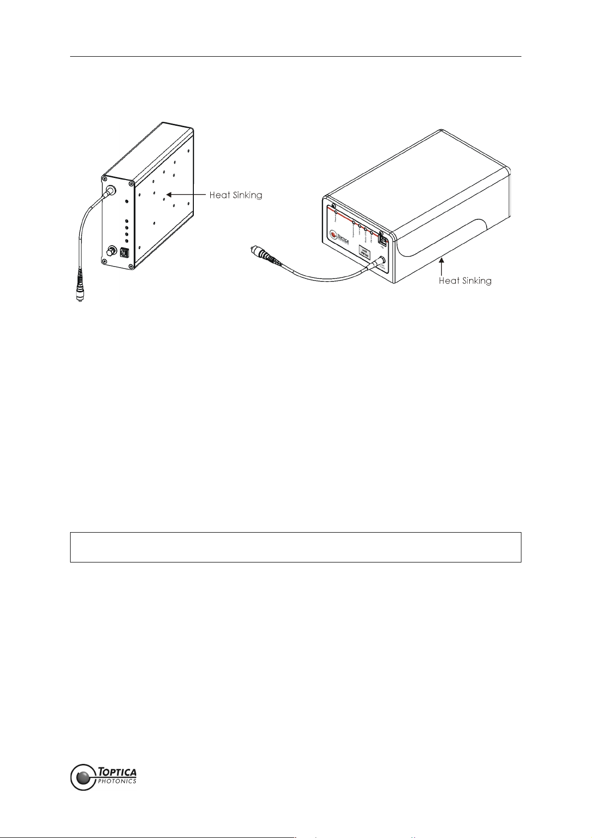
3.2 Installation Instructions
Figure 3 FemtoFiber smart laser (Femto/PicoFYb (left), FemtoFErb (right))
When installing the FemtoFiber smart laser the following instructions have to be observed:
• The FemtoFiber smart laser can be installed in any position. The protective housing has M4 threads
for fixing the FemtoFiber smart laser with screws (for main dimensions of the FemtoFiber smart lasers
and the location and depth of the M4 threads please see section 6.10).
• The FemtoFiber smart laser should only be installed at place free from vibrations.
• The FemtoFiber smart laser is designed for indoor usage, at altitudes below 2000 m.
• Environmental operating conditions: +15 °C .. +40 °C, the air humidity may not lead to condensation at or inside the laser housing. For a dew point table please refer to section 6.8.
Environmental transport/storage conditions: 0 °C .. +40 °C, non condensing.
• Weight: < 2.2 kg
• Depending on the individual system, the laser beam emits from the FC/APC connector(s) at the
FemtoFiber smart front panel, from the FC/APC-connector at the end of the fiber pigtail or free
beam. For location of the laser beam apertures please refer to section 6.10.
• For maximum stability, heat sinking of the base plate of the FemtoFiber smart laser to a typical
temperature of 22 ± 2° C is recommended.
Heat Dissipation: FYb laser heads typ. < 10 W, FErb laser heads typ. < 20 W.
CAUTION ! Avoid back reflection of the laser beam above 100 % (caused e.g. by a connected laser
amplifier).
Page 12
Statu s: 6.9.18
FemtoFiber smart Manual 4. Operation
4Operation
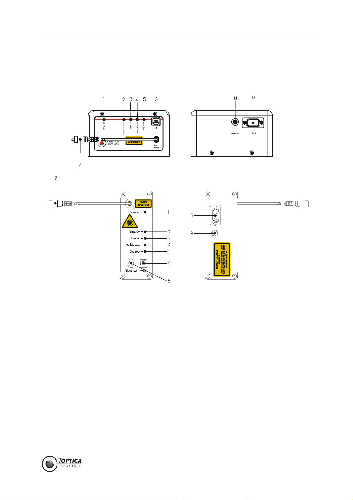
4.1 Operator Controls FemtoFiber smart Laser
Figure 4 Front and rear panel of FemtoFiber smart laser (FemtoFErb (top), Femto/PicoFYb (bottom))
1 Power ON LED 4 Module Error LED 7 Laser Output
2 Temperature OK LED 5 Clip Error LED 8 Trigger Out
3 Laser ON LED
(Laser Radiation Emission
Warning LED)
6 USB-connector 9 I/O D-Sub 9 Connector
Page 13
Statu s: 6.9.18

FemtoFiber smart Manual 4. Operation
1 Power ON LED The Power ON LED (blue, 1) lights up when the supply voltage
(12 ± 2 V DC filtered) is applied to the respective pins of the D-Sub 9-connector (9). For pin assignment please see section 6.2.
2 Temperature OK LED The Temperature OK LED (green, 2) lights up after the system is internally
stabilized and ready for operation.
3Laser ON LED
(Laser Radiation
Emission Warning
The Laser ON LED (orange, 3) indicates that the TTL input (Pin 7 of Input/
Output connector (9)) is in state high, i.e. the laser is ON and the laser
beam is emitted from the Laser Output (7).
LED)
DANGER ! When the orange Laser ON LED (Laser Radiation Emission
Warning LED) lights up, one has to be aware of laser emission.
4 Module Error LED The Module Error LED (red, 4) indicates a faulty connection between
Switch Box and laser head or a laser internal error. When the LED (4) lights
up continuously, please contact T
OPTICA.
5 Clip Error LED The Clip Error LED (yellow, 5) indicates that the laser did not start to oper-
ate after the TTL input (Pin 7 of Input/Output connector (9)) was set to
state high. When the LED (5) lights up continuously, please contact T
TICA.
OP-
6 USB-connector USB output connector type B for computer connection and control via
terminal program.
7 Laser Output FemtoFErb 780 Free beam laser output with mechanical shutter.
PicoFYb 1030/1064 FC/APC connector with connector tolerance for
FemtoFYb 1030 polarization maintaining fibers (narrow key,
2.02 mm)
FemtoFErb SC
FemtoFErb 1560 FD6.5 One FC/APC connector with connector tolerance
for polarization maintaining fibers (narrow key,
2.02 mm).
8Trigger Output
• SMA-connector
9 Input/Output
•D-Sub 9-connector
FemtoFErb 1560 Fiber pigtail (approx 20 cm long) with 3 mm cevlar
reinforced tubing and FC/APC-connector at the
end.
Output synchronous to the laser pulses for monitoring or triggering purposes (please refer to the Production and Quality Control Data Sheet for
signal properties).
NOTE ! FemtoFErb systems are using the direct output of a photo
diode as Trigger signal. There is no further (amplifying) electronics in order not to increase the signal jitter. Hence the
amplitudes of the signal are low, in the range of a few tens of
millivolts by nature. Please refer to the Production and Quality
Control Data Sheet for individual values.
General I/O connector for FemtoFiber smart operation. For pin assignment
please see section 6.2.
Page 14
Statu s: 6.9.18

FemtoFiber smart Manual 4. Operation
4.2 Operator Controls FemtoFiber smart Switch Box
Figure 5 Front and rear panel of FemtoFiber smart Switch Box
10 ON/OFF Switch 15 Power LED 21 Laser Power Input
11 Main Power Key Switch 16 FemtoFiber smart Supply LED 22 FemtoFiber smart Connector
12 Laser ON Push Button 17 FemtoFiber smart Error LED 23 Power Supply Connector
13 Micro Mover Push Button 18 Laser ON LED
(Laser Radiation Emission
Warning LED)
14 Pump Laser Power 19 Micro Mover LED 25 Interlock Connector
Adjustment 20 Power Monitor Output
24 Laser ON Input
Page 15
Statu s: 6.9.18

FemtoFiber smart Manual 4. Operation
10 ON/OFF Switch FemtoFiber smart Switch Box voltage supply and laser voltage supply are
switched ON/OFF by switch (10).
11 Main Power Key
General Switch for Switch Box voltage supply.
Switch
12 Laser ON Push Button Push button switches laser emission ON/OFF. Laser emission is indicated by
the Laser ON LED (18).
13 Micro Mover Push
Button
FYb Systems: When the laser does not start after the Laser ON Push But-
ton (12) has been pressed (i.e. the Clip Error LED (5) lights
up), the mirror chip inside the laser head can be moved
slightly by pressing the push button (13) twice.
Please note that the mirror chip can only be moved with
the laser emission switched off.
FErb Systems: Not supported.
14 Pump Laser Power
Adjustment
FErb Systems: Adjustment of the pump diode current from 90 % to 110 %
of the nominal pump diode current.
The zero position on the dial is equal to 90 %, while position 10 is equal to 110 %. The pump laser current adjustment can be used for fine tuning of the pulse
characteristics.
NOTE ! For normal operation, please leave the trimpot in mid position
(5 = 100 %) ! The system is checked and certified only for trimpot position 5. T
OPTICA Photonics AG does not guarantee that
the specifications of the laser are met at all other trimpot settings. Please refer to the Production and Quality Control Test
Data Sheet for specified values
FYb Systems: Adjustment of the pump diode current from 90 % to 100 %
of the nominal pump diode current.
The zero position on the dial is equal to 90 %, while position 10 is equal to 100 %. The pump laser current adjustment can be used for fine tuning of the pulse
characteristics.
NOTE ! For normal operation, please leave the trimpot in end position
(10 = 100 %) ! The system is checked and certified only for trimpot position 10. T
OPTICA Photonics AG does not guarantee that
the specifications of the laser are met at all other trimpot settings. Please refer to the Production and Quality Control Test
Data Sheet for specified values
15 Power LED This green LED indicates proper voltage supply of the Switch Box.
16 Supply LED The Supply LED (blue, 16) lights up when the supply voltage is applied to
the FemtoFiber smart laser.
17 Error LED The Error LED (red, 17) indicates a faulty connection between Switch Box
and laser head or a laser internal error. When the LED (17) lights up contin-
18 Laser ON LED
(Laser Radiation
uously, please contact T
The Laser ON LED (orange, 18) indicates that the laser is ON and the laser
beam is emitted from the Laser Output (7).
OPTICA.
Emission Warning
LED)
DANGER ! When the orange Laser ON LED (Laser Radiation Emission
Warning LED) lights up, one has to be aware of laser emission.
Page 16
Statu s: 6.9.18

FemtoFiber smart Manual 4. Operation
19 Micro Mover LED FYb Systems: The Micro Mover LED (19) lights up after one push at the
Micro Mover Push Button (13) and goes off after the second push, when the mirror chip has been moved.
FErb Systems: Not supported.
20 Power Monitor Output
• SMA-connector
21 Laser Power Input
• SMA-connector
22 FemtoFiber smart
Connector
•D-Sub 9-connector
23 Power Supply
Connector
24 Laser ON Input
• Tyco AMP 828549
connector
Oscillator Power Monitoring, Output Voltage 0 .. 4.5 V for 0 .. 100 %
(does not represent the laser output power exactly)
Input for Analog Laser Power Control (for details please refer to section
6.3).
FErb Systems: 0..5mA via R=1kΩ, Range 90 - 110 % additional to the
Pump Laser Power Adjustment (14).
FYb Systems: 0..5mA via R=1kΩ, Range 90 - 100 % additional to the
Pump Laser Power Adjustment (14).
NOTE ! When the laser power is controlled via the Laser Power Input
(21), the Pump Laser Power Adjustment potentiometer (14)
should be turned to min. position to avoid interference
between the two controls.
Connection to the FemtoFiber smart laser.
Connection to the FemtoFiber smart Power Supply.
For pin assignment please refer to section 6.5.
Input to switch laser emission ON/OFF.
TTL high (+ 3.3 V..+ 5 V) Laser ON, TTL low (0 V..+ 0.8 V) Laser OFF.
Laser emission is indicated by the Laser ON LED (18).
For pin assignment please refer to section 6.4.
25 Interlock Connector
• Phoenix MC0.5/2-G-
2.5 connector
Connector for installation of an external interlock circuit. For first operation,
an interlock plug is supplied to close the interlock circuit. For safety reasons, the installation of an external interlock circuit is strongly recommended.
Page 17
Statu s: 6.9.18

FemtoFiber smart Manual 4. Operation
4.3 FemtoFiber smart System Quickstart
CAUTION ! Since the FemtoFiber smart has power levels which may already destroy optical fibers,
please pay special attention to a clean fiber facet at the output fiber connector. We also
recommend to always switch-off the laser emission before the fiber connector is opened/
closed!
CAUTION ! While starting the laser it may occur that higher level pulses are sent out by the laser. This
transient phenomenon is due to the fact that the amplifier of the system starts simultaneously with the oscillator. We therefore recommend blocking the output beam at the
moment when the laser is switched on, or adding the THz option.
NOTE ! The FemtoFiber smart is specified to be ready for operation within 15 seconds after switch-
on, provided that the laser emission start signal is given right after the boot-up sequence,
which takes approx. 3 seconds. The end of the boot-up sequence is indicated at the laser
head when the Power ON LED (1, blue) and the Temperature OK LED (2, green) light up
(all other LEDs are off).
If laser emission is activated before reaching this state, an error may occur, indicated by
the Clip Error LED (3, yellow) or Module Error LED (4, red).
4.3.1 OEM Integrated Environment
1. Connect the FemtoFiber smart laser to the application via the I/O connector (9). For pin assign-
ment please see section 6.2.
2. Connect the FemtoFiber smart laser Output FC/APC connector (7) to the application.
3. When the FemtoFiber smart laser supply voltage (pin 1 of the I/O connector (9)) is applied and the
TTL input (pin 7 of the I/O connector (9)) is in state high, the laser emission is ON.
Page 18
Statu s: 6.9.18

FemtoFiber smart Manual 4. Operation
4.3.2 Manual Operation via Switch Box
NOTE ! For Switch Box operator controls please refer to section 4.2.
1. Unpack all system items.
Systems with fixed fiber: Remove the protection cap from the fiber pigtail and plug in the FC/APC
connector into the receptacle of the application, optionally to the F
orientated parallel to the slow axis of the fiber.
Systems with FC/APC fiber connector: Use the supplied fiber to connect the FemtoFiber smart to
the application. Remove the protection caps from both ends of the fiber. Connect the fiber to the
FC/APC connector of the FemtoFiber smart laser and to the receptacle of the application, optionally to the F
IBEROUT. The connector key is orientated parallel to the slow axis of the fiber.
Systems with free beam laser output: Make sure the laser beam shutter is closed for safety reasons
(please refer to section 2.4.2).
2. Connect the FemtoFiber smart laser to the Switch Box via the D-Sub 9 cable and fix it with the
screws.
3. Make sure that the Main Power Key switch (11) is in OFF position. Connect the power supply to the
Switch Box and to mains.
IBEROUT. The connector key is
4. Remove the protection cap from the Trigger Output (8) and connect to the trigger input of the
application (if necessary).
5. Turn the Main Power Key switch (11) into position ON.
6. Set the Pump Laser Power Adjustment potentiometer (14) on the Switch Box to position 10 (FYb
systems), respectively 5 (FErb systems).
7. Switch ON the FemtoFiber smart system with the ON/OFF Switch (10) and wait until the green Temperature OK LED (2) on the FemtoFiber smart laser head lights up.
8. To enable the laser emission, press the Laser ON Push Button (12). The Laser On LED (18) will light up
and laser light is emitted. The FemtoFiber smart laser can be operated via the operator controls at
the Switch Box (see section 4.2).
Systems with free beam laser output: Open the laser beam shutter (please refer to section 2.4.2).
When the laser is disabled, close the laser beam shutter for safety reasons.
NOTE ! When the emission of the FemtoFiber smart laser is switched on with closed shutter, back
reflections from the shutter may disturb the internal photo diode/power regulation. This
may lead to unexpected error messages, but is not harmful to the laser.
Page 19
Statu s: 6.9.18

FemtoFiber smart Manual 4. Operation
4.3.3 FemtoFiber smart Operation via Software Commands
4.3.3.1 Installation of USB Connection
NOTE ! For Switch Box operator controls please refer to section 4.2.
In order to connect a FemtoFiber smart to a computer for the first time, please follow the instructions
noted below for the initial installation:
1. Switch ON the computer.
2. Switch ON the FemtoFiber smart.
Switch Box: Switches (10) and (11) in position ON.
OEM: I/O connector (9) connected, 12 ± 2 V DC applied at pin 1
3. Connect the USB cable to the USB-connector (6) on the FemtoFiber smart first and then connect it
to the computer (Windows 7 or higher required).
4. Please install the USB driver as described in section 6.7.
5. Open a terminal program and select a serial connection with the following settings:
Baud rate 9600
8 bits
no parity
1 stop bit
no hardware handshake
The COM port for communication with the FemtoFiber smart is usually the newest added USB Serial
Port or the one with highest COM port number.
6. Switch the laser OFF and ON.
Switch Box: Switch (10) in position OFF and ON.
OEM: I/O connector (9) connected, 12 ± 2 V DC at pin 1 removed and applied.
You should see a prompt appearing at the terminal window which includes the current firmware
number.
Example:
FemtoFErb 2.0.87>
After the USB connection is installed and works properly, the laser can be remote controlled. For a command list, please refer to section 4.3.3.2.
DANGER ! When the FemtoFiber smart is remote controlled via software commands, the Laser ON LED
on the Switch Box does not show the actual status of the laser !
NOTE ! As per default after start-up, the FemtoFiber smart can only be controlled by the hardware
input lines (D-Sub-9 connector), i.e. via Switch Box.
To control a FemtoFiber smart via software commands, the hardware input lines (i.e.
Switch Box operation), have to be disabled by the corresponding command (please see
section 4.3.3.2). It is not possible to control the laser in both ways at the same time, either
hardware (D-Sub-9) or software (USB) control is possible.
NOTE ! After switching off the FemtoFiber smart power supply, all settings will be lost, i.e. the laser is
in hardware control mode again as per default.
Page 20
Statu s: 6.9.18

FemtoFiber smart Manual 4. Operation
4.3.3.2 Commands for Remote Control
NOTE ! The syntax must include all shown characters and symbols (brackets, apostrophes, !, #, ...)
Mode W = write, Mode R = read.
Command/Parameter Syntax Return Type Mode Description
(param-set! 'hw-input-dis #t) BOOLEAN W Enable remote control
(#t: true, #f: false)
(param-ref 'hw-input-dis) BOOLEAN R Remote control status
#t: write commands will be executed
#f: write commands disabled
(param-set! 'laser:en #t) BOOLEAN W Switch ON/OFF laser
(param-ref 'laser:en) BOOLEAN R Laser ON/OFF status
(param-ref 'laser:i) INTEGER R Laser current in Milliampere (mA)
(param-ref 'laser:pd-i) INTEGER R Photodiode monitor level in arb. units
(param-ref 'tec1:temp) INTEGER R Pump diode TEC temperature in 0.1
celsius degrees (°C).
(param-set! 'poti-pos xxxx) INTEGER W Set output power (0..1000)
(param-ref 'poti-pos) INTEGER R Output power (0..1000) corresponds
to:
0 > Switch Box Trimpot Position 0
1000 > Switch Box Trimpot Position
10.00
NOTE ! The system is checked
and certified only for
100 % nominal output
power. This is equal to
Switch Box Trimpot position 5 (FErb systems), or
10 (FYb systems). Please
refer to the Production
and Quality Control Test
Data Sheet for specified
values.
T
OPTICA Photonics AG
does not guarantee that
the specifications of the
laser are met at all other
trimpot settings
(param-set! 'powercontrol:en #t) BOOLEAN W Enable power control loop
Page 21
Statu s: 6.9.18

FemtoFiber smart Manual 4. Operation
(param-ref 'powercontrol:en) BOOLEAN R Power control loop status
#t: Poti controls power value
#f: Poti controls current value
(param-ref 'laseron:time) STRING R Laser operation time in Seconds (s)
(param-ref 'laseron:cycles) STRING R Counter of "laser on" operations
(param-ref 'laseron.uptime) STRING R "Power-on" time in Seconds (s)
(param-ref 'serial-number) STRING R Readout of serial number
(param-ref 'system-type) STRING R Returns a string containing the
device type
(param-ref 'system-model) STRING R Returns a string describing the hard-
ware setup device
(param-ref 'fw-ver) STRING R Returns firmware number
(param-ref 'status) INTEGER R Status parameter bit code
bit 0 - Current error
bit 1 - Low voltage error
bit 2 - Laser current clip active
bit 3 - TEC1 error
bit 4 - Control loop overflow error
bit 5 - Modelock error
bit 6 - QML error
bit 7 - TEC 2 error
bit 8 - EEPROM error</description>
Page 22
Statu s: 6.9.18

FemtoFiber smart Manual 4. Operation
4.3.4 FemtoFiber smart Operation with Graphical User Interface
4.3.5 System Requirements
Control computer with Windows operating system, up to Windows 10.
4.3.5.1 Installation of TOPAS FemtoFiber smart
NOTE ! You will need to have administrator rights to run the setup. If you don't have logged in with
such rights, you will need to logon as such first. As an alternative, you may also run
setup.exe under a different user while using right-mouse-click and select "run as..."
The following installation procedure is described with Windows 7/8, other operation systems may show different windows. In this case, please follow the steps accordingly.
For TOPAS FemtoFiber smart installation, please insert the supplied USB flash drive to the control computer
and start the installer (TOPAS FemtoFiber smart.exe). The installer will guide you through the installation
process.
Figure 6 TOPAS FemtoFiber smart installation
Start the installation by clicking Next and confirm the license agreement by clicking IAgree.
Figure 7 TOPAS FemtoFiber smart installation
Page 23
Statu s: 6.9.18

FemtoFiber smart Manual 4. Operation
Select the folder where TOPAS FemtoFiber smart will be installed. Click Next to continue to the following
window.
In your software version, all components of TOPAS FemtoFiber smart will be installed. In the next window (Figure 7 right) you may choose the name of a program folder in the start menu. Click Install to continue.
Figure 8 TOPAS FemtoFiber smart installation
After the installation is completed, click Finish to close the TOPAS FemtoFiber smart installer.
Page 24
Statu s: 6.9.18

FemtoFiber smart Manual 4. Operation
4.3.5.2 FemtoFiber smart Operation with TOPAS FemtoFiber smart
NOTE ! Please refer to section 4.1 for a detailed description of the operator controls on the
FemtoFiber smart front and rear panel and to section 5 for a detailed description of the
TOPAS FemtoFiber smart graphical user interface (GUI).
1. Connect the FemtoFiber smart to your OEM environment (see section 4.3.1) or to the Switch Box
(see section 4.3.2).
Connect the USB-connector on the FemtoFiber smart front panel with a USB connector of your PC
by using the supplied USB cable. Switch ON the FemtoFiber smart laser at the Switch Box.
NOTE ! When no USB serial port is detected, please check whether a FTDI driver is installed on the
computer. Verified FTDI drivers can be downloaded from the product pages on the T
TICA website.
2. Start TOPAS FemtoFiber smart.
3. Select Menu > Connection Settings
OP-
Figure 9 TOPAS FemtoFiber smart menu
To be continued on the next page.
Page 25
Statu s: 6.9.18

FemtoFiber smart Manual 4. Operation
Figure 10 TOPAS FemtoFiber smart Connection Settings window
4. In the Connection Settings window, select the USB Serial Port to which the device is connected.
Baudrate and Settings are preset and fixed for FemtoFiber smart operation. Click OK to save the
settings and to close the window.
NOTE ! If there is no USB serial port found in the TOPAS FemtoFiber smart list of available lasers -
although the laser is properly connected, switched on and ready to work, it probably
helps to try one of the following solutions:
1) Try to run TOPAS FemtoFiber smart in "XP compatibility mode" (right click on the TOPAS
icon > properties > compatibility). This feature is forcing Windows to emulate XP conditions
and may solve port access issues.
2) Try a "right-mouse-click" on the TOPAS icon and select "run as administrator". Independently from the individual user rights of the computer, TOPAS FemtoFiber smart is run under
administrator rights, without needing to have a password.
3) The USB cable is probably too long or the outputs at the USB port of the computer are
very low. The first problem may appear when the USB-cable is longer than 2 meters. The
second one often appears when a laptop or a tablet computer is used. In both cases, the
signal gets too weak at receiver's side and the communication may be disrupted. In our
experience, establishing the first connection is usually still possible, but in some cases
exchanged commands get lost and either GUI or laser are not operating properly. Do not
use a USB cable longer than the factory supplied one. Alternatively you can try to use a
powered USB hub with an external power supply.
5. Select Menu > Connect to establish a connection to the device.
6. The laser can now be operated with the Controls of the GUI (see section 5).
Page 26
Statu s: 6.9.18

FemtoFiber smart Manual 5. TOPAS FemtoFiber smart Control Software
5 TOPAS FemtoFiber smart Control Software
In this section all controls of the TOPAS FemtoFiber smart graphical user interface (GUI) are described in
detail.
5.1 Upper and Lower Screen Section
5.1.1 Header
Figure 11 TOPAS FemtoFiber smart header
Menu Please refer to section 5.1.3.
Help Please refer to section 5.1.4.
Connected Device Displays the connected device and its serial number.
Laser Warning Label The laser warning label appears when laser light is emitted by the
connected device (please refer to section 5.2).
Indicators The five indicators on top to the right correspond to the LEDs on the
FemtoFiber smart front panel (please refer to section 4.1).
5.1.2 Footer
Figure 12 TOPAS FemtoFiber smart footer
Connection: Displays the connection currently used for communication with the
device.
Device Communication: Bright green: Communication.
Dark green: No communication.
Page 27
Statu s: 6.9.18

FemtoFiber smart Manual 5. TOPAS FemtoFiber smart Control Software
5.1.3 Menu
Figure 13 TOPAS FemtoFiber smart menu
Menu > Connect Establishes a connection to the device selected in the Connection
Settings window.
Page 28
Statu s: 6.9.18

FemtoFiber smart Manual 5. TOPAS FemtoFiber smart Control Software
Menu > Connection Settings The Connection Settings window opens where the connection can
be configured.
Figure 14 TOPAS FemtoFiber smart Connection Settings Window
Serial Port Select the USB Serial Port where the device is connected to.
Baudrate The Baudrate is fixed to 9600 for FemtoFiber smart operation.
Settings The Settings for the communication are preset and fixed for
FemtoFiber smart operation.
Test Connection Clicking opens a window where details on the connected device
are shown.
Connect on Startup When checked, the connection saved by clicking OK is automati-
cally established at the next software start.
Search not active
Display Identification/Address not active
OK Saves the settings and closes the window.
Cancel Closes the window.
Menu > Disconnect Closes the connection to the device.
Page 29
Statu s: 6.9.18

FemtoFiber smart Manual 5. TOPAS FemtoFiber smart Control Software
Menu > Firmware Update Opens the Firmware Update window.
Figure 15 TOPAS FemtoFiber smart Firmware Update window
NOTE ! Please refer to section 6.6 for a detailed description of the firmware update procedure.
Serial Port Displays the USB Serial Port where the device is connected to.
Select Choose the firmware file (*.elf) to be installed. The selected firmware
file is displayed in the display field.
Start Starts the firmware update.
Abort Aborts the firmware update.
Log window Displays details on the process of the firmware update.
Close Closes the Firmware Update window.
Page 30
Statu s: 6.9.18

FemtoFiber smart Manual 5. TOPAS FemtoFiber smart Control Software
Menu > Log Adds the Log window to the bottom section of the screen.
Menu > Communication Adds the Communication window to the bottom section of the
screen.
NOTE ! When you display Log and Communication windows at the same time, you can display
one window at full size in the front for better viewing. Do this by picking the window at the
title bar and pulling it in the center of the screen area.
Each display window may also be moved to any screen position when picked at the title
bar.
Figure 16 TOPAS FemtoFiber smart Log and Communication window
Log Window The Log Window shows TOPAS FemtoFiber smart internal debug mes-
sages.
Loglevel Selection of the Loglevel displayed in the Log Window
Error Only Error messages are displayed.
Warning Error and Warning messages are displayed.
Info Error and Warning messages as well as additional
detailed information on the system operation are displayed.
Save Log The currently displayed log is saved.
Communications Window The Communications Window shows the communication between
TOPAS FemtoFiber smart and the FemtoFiber smart.
Show Monitoring Line/ Click to toggle between display of communication on the
Show Command Line monitoring or the command line.
NOTE ! Communication on monitoring line is not active with FemtoFiber smart lasers.
Hold Freezes the display of the communication. Click Hold again to con-
tinue the display.
Monitoring Line/ Display area for communication between TOPAS FemtoFiber smart
Command Line and the FemtoFiber smart.
Menu > About The About window opens, which provides information about the
manufacturer, contact details, software version, etc.
Menu > Exit Closes the TOPAS FemtoFiber smart software.
5.1.4 Help
Clicking opens a pdf version of the FemtoFiber smart manual.
Page 31
Statu s: 6.9.18

FemtoFiber smart Manual 5. TOPAS FemtoFiber smart Control Software
5.2 Control Section
Figure 17 TOPAS FemtoFiber smart controls (FErb system shown)
Emission Indicates and controls the emission of the laser.
Indicator OFF: No laser emission.
Indicator green: Laser emission is turned on.
Click the Emission button to toggle the emission state.
Hardware Disable Click the Hardware Disable button to toggle between GUI operation
(hardware disabled) or e.g. Switch Box operation of the FemtoFiber
smart. At software start, by default the button is set to hardware disabled.
When hardware is disabled, the Switch Box display and control elements are not active.
DANGER ! When the FemtoFiber smart is remote controlled via TOPAS FemtoFiber smart, the Laser ON
LED on the Switch Box does not show the actual status of the laser !
Page 32
Statu s: 6.9.18

FemtoFiber smart Manual 5. TOPAS FemtoFiber smart Control Software
Switchbox Trimpot Position Enter a number or move the slider to change the laser power similar
to a Laser Power trimpot adjustment on the Switch Box .
The adjustment can be used for fine tuning of the pulse characteristics.
NOTE ! The position of the Laser Power trimpot on the Switch Box is read out and displayed when
the FemtoFiber smart is connected (Menu > Connect) to the TOPAS FemtoFiber smart software. Small deviations due to component tolerances are possible.
NOTE ! The system is checked and certified only for 100 % nominal output power. This is equal to
Switch Box Trimpot position 5 (FErb systems), or 10 (FYb systems). Please refer to the Production and Quality Control Test Data Sheet for specified values.
T
OPTICA Photonics AG does not guarantee that the specifications of the laser are met at all
other trimpot settings
5.2.1 System Info Tab
The System Info section (see Figure 17) provides detailed information on the FemtoFiber smart system setup.
System Info Section
Temperatures
Pump Diode (°C) Displays the temperature of the pump diode.
System Status
Laser on Time (h) Displays the accumulated time where laser light was emitted.
Uptime (h) Displays the accumulated system uptime.
Start Counter Displays the number of emission ON cycles.
Firmware Version Displays the current firmware version.
Power Consumption Displays the internal power consumption index.
Page 33
Statu s: 6.9.18

FemtoFiber smart Manual 5. TOPAS FemtoFiber smart Control Software
5.2.2 Micro Mover Tab (only FYb Systems)
Figure 18 TOPAS FemtoFiber smart Micro Mover tab (only FYb systems)
Display The current spot position is shown with a yellow background.
Spot Runtime (h) Displays the accumulated operating time on the respective spot
position.
Laser Starts Displays the number of emission ON cycles on the respective spot
position.
Move one step A dialog windows opens. Select Execute to move the SAM to the
next spot position by the micro mover.
NOTE ! Moving the SAM to the next spot position is only possible with the laser emission switched
off !
Refresh The content of the display is refreshed.
Current Position Displays the current spot position.
Page 34
Statu s: 6.9.18

FemtoFiber smart Manual 6. Appendix
6Appendix
6.1 Specifications
For current specifications of the FemtoFiber smart systems please refer to the TOPTICA website and to the
Production and Quality Control Data Sheet.
6.2 Pin Assignment D-Sub 9 Input/Output Connector
Figure 19 Input/output D-Sub 9 connector at FemtoFiber smart laser rear panel
Pin 1 12 ± 2 V DC filtered (supply)
Pin 2 GND (TTL)
Pin 3 TTL signal micro mover (optional)
Pin 4 GND (analog)
Pin 5 Analog Laser Power Control, Range 90 - 110 % (please refer to section 6.3 for details)
Pin 6 GND (supply)
Pin 7 TTL high (+ 2 V..+ 5 V) Laser ON, TTL low (0 V..+ 0.8 V) Laser OFF
Pin 8 Error low = error (monitor signal e.g. for external control)
Pin 9 Oscillator Power Monitoring, Output Voltage 0 .. 4.5 V for 0 .. 100 %
(does not represent the laser output power exactly)
Page 35
Statu s: 6.9.18

FemtoFiber smart Manual 6. Appendix
6.3 Operation without Switch Box (Control via TTL/Analog Pins)
If a FemtoFiber smart laser head is operated without Switch Box, the Pump Laser Power Adjustment trimpot setting has to be replaced by the Analog Laser Power Control applied to pin 5 of the Input/Output DSub 9 connector.
NOTE ! This information is not valid for OEM integrators intending to use USB control and not TTL/
analog signals to control the laser.
FErb Systems: All FErb laser heads are specified at 100 % laser power with trimpot setting 5/mid position.
To be within specification, 100 % laser power has to be adjusted by an external laser
power control circuit when the Switch Box is not used.
FYb Systems: All FYb laser heads are specified at 100 % laser power with trimpot setting 10/end posi-
tion. To be within specification, 100 % laser power has to be adjusted by an external laser
power control circuit when the Switch Box is not used.
Figure 20 Setup for FemtoFiber smart operation without Switch Box
Examples for Analog Laser Power Control voltages applied to pin 5 of the Input/Output D-Sub 9 connector and the corresponding laser power are noted in the table below:
FErb System
Laser Power
90 % 90 %
100 % 95 %
110 % 100 %
FYb System
Laser Power
R ext = 1 kΩ R ext = 0
0V 0V
5V 2.5V
10 V 5 V
Page 36
Statu s: 6.9.18

FemtoFiber smart Manual 6. Appendix
6.4 Pin Assignment of Laser On Input Connector (Switch Box)
Figure 21 Tyco AMP 828549 connector
Pin 1: TTL high (+ 3.3 V..+ 5 V) Laser ON, TTL low (0 V..+ 0.8 V) Laser OFF
Pin 2: GND
6.5 Pin Assignment of Power Supply Connector (Switch Box)
Figure 22 Power supply connector
Page 37
Statu s: 6.9.18

FemtoFiber smart Manual 6. Appendix
6.6 Firmware Update
The file (*.elf) for updating the FemtoFiber smart firmware is provided by TOPTICA. Please follow the
description below for updating the firmware.
Prerequisites:
• FTDI Driver installed on the control computer.
• TOPAS FemtoFiber smart software installed on the control computer.
• FemtoFiber smart laser head connected to the control computer.
• FemtoFiber smart laser head switched off.
• The firmware file (*.elf) is available on the control computer.
1. Run the TOPAS FemtoFiber smart software and select Menu > Firmware Update. The Firmware
Update window appears (see also section 5.1.3).
Figure 23 TOPAS FemtoFiber smart Firmware Update window
2. Click Select and chose In the firmware file (*.elf) on the control computer.
3. Move the mouse pointer over the Start button but do not click, yet.
4. Switch off the FemtoFiber smart laser head.
5. Switch the FemtoFiber smart laser head back on. Now click the Start button in the TOPAS FemtoFi-
ber smart Firmware Update window within one second - otherwise the update will not take place.
6. The firmware update takes about 2 minutes. A successful update is indicated by the message
“Update successful”. In case of an error, please repeat from step 3.
7. After a successful firmware update, please switch the FemtoFiber smart laser head off and back
on. Establish a connection to TOPAS FemtoFiber smart.
8. The Firmware Version can be checked in the System Info tab (System Status section) of
TOPAS FemtoFiber smart. Please note that the file name may be truncated.
Page 38
Statu s: 6.9.18

FemtoFiber smart Manual 6. Appendix
6.7 USB Connection (Installation of FTDI CDM Drivers)
NOTE ! You will need to have administrator rights to run the setup. If you don't have logged in with
such rights, you will need to logon as such first. As an alternative, you may also run
setup.exe under a different user while using right-mouse-click and select "run as..."
NOTE ! Since support of Windows XP has been terminated recently, T
or older operating systems. The following procedures are executed on a Windows 7 system, also including some special remarks on Windows 8.
Operation with Windows 10 has been verified at time of issuing this manual.
NOTE ! Newest and latest FTDI drivers can always be found at the manufacturer's website:
http://www.ftdichip.com/Drivers/VCP.htm
Insert the supplied USB flash drive to the control computer and select the folder FemtoFiber-smart-USB-
Driver_Windows (Figure 24).
OPTICA no longer supports this
Figure 24
For USB driver installation, please insert the supplied USB flash drive to the control computer and start the
installation wizard (CDM xxx.exe). The installation wizard will guide you through the installation process.
Figure 25 USB driver installation
Start the installation by clicking Extract. Continue to install by clicking Next.
Page 39
Statu s: 6.9.18

FemtoFiber smart Manual 6. Appendix
Figure 26 USB driver installation
Click Finish to complete the installation.
Page 40
Statu s: 6.9.18

FemtoFiber smart Manual 6. Appendix
6.8 Precautions for Non-Condensing Operation Conditions
For FemtoFiber smart lasers, the typical temperature inside the housing is approximately 4 °C above the
ambient temperature. This means, however, that especially in warm and humid surroundings, there
could be condensation at relatively cold parts of the FemtoFiber smart – this is a condition that has to be
prevented. Please refer to the dew point table below to see if the environmental conditions are appropriate for the operation of the FemtoFiber smart.
A safe operating condition for the FemtoFiber smart is reached when the dew point is below the typical temperature inside the housing. For safety reasons, there should be a small margin of 2 °C. Please
check with the dew point table whether at your ambient conditions there may be a risk of condensation.
Ambient Temperature in °C 15 20 25 30 35 40 45
Ambient Temperature in °F 59 68 77 86 95 104 113
Relative Ambient Humidity Dew Points at corresponding Ambient Conditions
90% 13,4 18,3 23,2 28,2 33,1 38,0 43,0
85% 12,5 17,4 22,3 27,2 32,1 37,0 41,9
80% 11,6 16,4 21,3 26,2 31,0 35,9 40,7
75% 10,6 15,4 20,3 25,1 29,9 34,7 39,5
70% 9,6 14,4 19,1 23,9 28,7 33,5 38,2
65% 8,5 13,2 18,0 22,7 27,4 32,2 36,9
60% 7,3 12,0 16,7 21,4 26,1 30,7 35,4
55% 6,0 10,7 15,3 20,0 24,6 29,2 33,9
50% 4,7 9,3 13,9 18,4 23,0 27,6 32,2
45% 3,2 7,7 12,2 16,8 21,3 25,8 30,3
40% 1,5 6,0 10,5 14,9 19,4 23,8 28,3
35% -0,3 4,1 8,5 12,9 17,3 21,6 26,0
30% -2,4 1,9 6,2 10,5 14,8 19,1 23,4
25% -4,9 -0,6 3,6 7,8 12,0 16,2 20,4
20% -7,8 -3,7 0,5 4,6 8,7 12,8 16,8
Table 1 Dew point table
Page 41
Statu s: 6.9.18

FemtoFiber smart Manual 6. Appendix
6.9 Declaration of CE Conformity
Page 42
Statu s: 6.9.18

FemtoFiber smart Manual 6. Appendix
6.10 Main Dimensions of the FemtoFiber smart System Versions
6.10.1 FemtoFErb Free Beam
Figure 27 Main dimensions of FemtoFErb with free beam laser output
Page 43
Statu s: 6.9.18

FemtoFiber smart Manual 6. Appendix
6.10.2 FemtoFErb with Fiber Pigtail
Figure 28 Main dimensions of the FemtoFErb with fiber pigtail
Page 44
Statu s: 6.9.18

FemtoFiber smart Manual 6. Appendix
6.10.3 FemtoFErb with FC/APC Fiber Connector
Figure 29 Main dimensions of the FemtoFErb with FC/APC fiber connector
Page 45
Statu s: 6.9.18

FemtoFiber smart Manual 6. Appendix
6.10.4 Femto/PicoFYb with Fiber Pigtail
Figure 30 Main dimensions of the Femto/PicoFYb with fiber pigtail
Page 46
Statu s: 6.9.18

FemtoFiber smart Manual 6. Appendix
6.11 License and Copyright Information associated with Third Party
Software
This product incorporates certain third party software. The license and copyright information associated
with this software is available in the folder Software License and Copyright Information on the supplied
USB flash drive.
Please address your request to T
82166 Graefelfing, Germany. This offer is valid during a 3-years-period beginning at the purchase date.
OPTICA Photonics AG, Head of Development, Lochhamer Schlag 19,
6.12 EU Legislation for Electrical and Electronic Equipment (EEE)
Companies selling electrical and electronic goods in the European Union must conform to the EU legislation for electrical and electronic equipment (EEE), which includes the Waste Electrical and Electronic
Equipment Directive (WEEE). Assigned duties affect product design of the equipment, disposal of used
appliances as well as organizational responsibilities, i.e. product registration.
There are different requirements for household WEEE and that which is sold business to business (B2B).
All equipment T
Authority (Stiftung Elektro-Altgeräte Register EAR) under No. DE70442884.
At end-of life return your product back to T
ner as to meet all relevant local, country and EU requirements and guideline.
OPTICA Photonics AG handles is classed as B2B. TOPTICA is registered at the Competent
OPTICA. TOPTICA will dispose used equipment in such a man-
To return products please mark them clearly with “intended for disposal”. Contact T
ping and send them to the following address:
T
OPTICA Photonics AG
Lochhamer Schlag 19
D-82166 Graefelfing
OPTICA prior to ship-
Page 47
Statu s: 6.9.18

FemtoFiber smart Manual 7. Guarantee and Service
7 Guarantee and Service
On the following page you will find the Guarantee Registration Form in which the warranty conditions are
defined. Please complete in the Guarantee Registration Form immediately after you receive your device
and return it to T
As a first step towards obtaining technical support, please contact your local distributor or visit the
support pages on our web site: http://www.toptica.com/support/.
In case you wish to return a product for diagnosis and/or repair, please contact us prior to sending it
so we can issue a Return Material Authorization (RMA) number for you.
You can contact us in the following ways:
- Internet: service.toptica.com. In our support section you can find a list of frequently asked ques-
- Email: service@toptica.com
- Phone: +49-89-85837-150
OPTICA Photonics AG by mail or fax.
tions and a service contact form.
Our customers in the USA and Canada may contact T
- Phone: +1-585-657-6663
Our customers in Japan may contact T
OPTICA Photonics K.K.:
- Phone: +81-42-306-9906
OPTICA Photonics Inc.:
Page 48
Statu s: 6.9.18

 Loading...