

Toptech TT-N-705, T705 Installation Manual
INSTALLATION MANUAL
This manual covers TopTech models:
TT-N-705 and T705
Thermostat Applications Guide
noitpircseD
Gas or Oil Heat
Electric Furnace
Heat Pump (No Aux. or Emergency Heat)
Heat Pump (with Aux. or Emergency Heat)
Multi-stage Systems
Heat Only Systems
Heat Only Systems - Floor or Wall Furnaces
Cool Only Systems
Millivolt
Table of Contents
Installation Tips
Thermostat Quick Reference
Subbase Installation
Wiring
Wiring Diagrams
Technician Setup
Technician Setup Menu
Mounting and Battery Installation
Programming The Thermostat
Programming The Thermostat (cont)
Specifications
Una versión española de este
manual puede ser descargada
en www.pro1iaq.com
Yes
Yes
Yes
No
No
Yes
Yes
Yes
Yes
Page
2
3
4
5
6
7
8
9
10
11
12
Power Type
Battery Power
Hardwire (Common Wire)
Hardwire (Common Wire) with Battery Backup
A trained, experienced technician
must install this product.
Carefully read these instructions. You
could damage this product or cause a
hazardous condition if you fail to follow
these instructions.
Need Help?
For assistance with this product please visit
http://www.pro1iaq.com or call Pro1
Customer Care toll-free at 888-Pro1iaq
(776-1427) during normal business hours
(Mon-Fri 9 AM - 6 PM Eastern)
® U.S. Registered Trademark. Patents pending.
Copyright © 2006 Pro1 IAQ, Inc. All rights reserved.
Rev. 0850
1
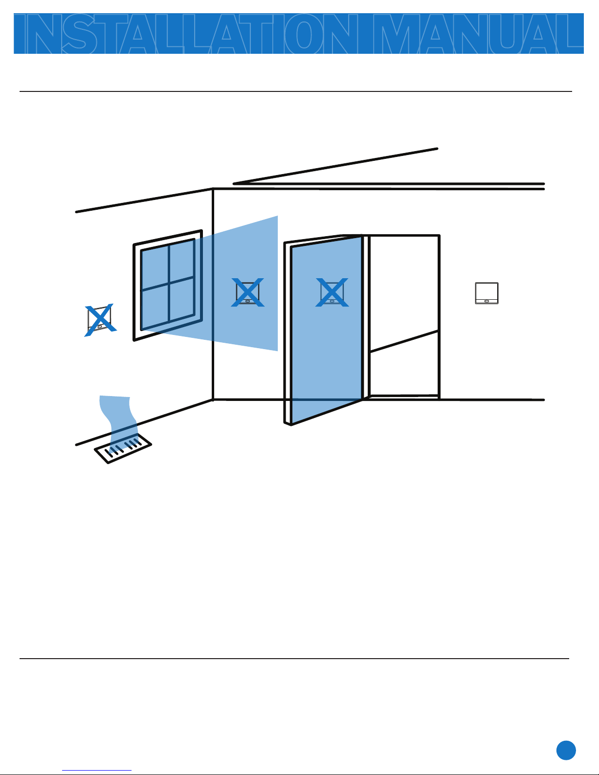
Wall locations
The thermostat should be installed approximately 4 to 5 feet above the floor.
Select an area with average temperature and good air circulation.
INSTALLATION TIPS
NO NO YES
NO
Do not install thermostat in locations:
• Close to hot or cold air ducts
• That are in direct sunlight
• With an outside wall behind the thermostat
• In areas that do not require conditioning
• Where there are dead spots or drafts (in corners or behind doors)
• Where there might be concealed chimneys or pipes
PRO1 Tip
Pick an installation location that is easy for the user to access. The temperature of the location
should be representative of the building.
2
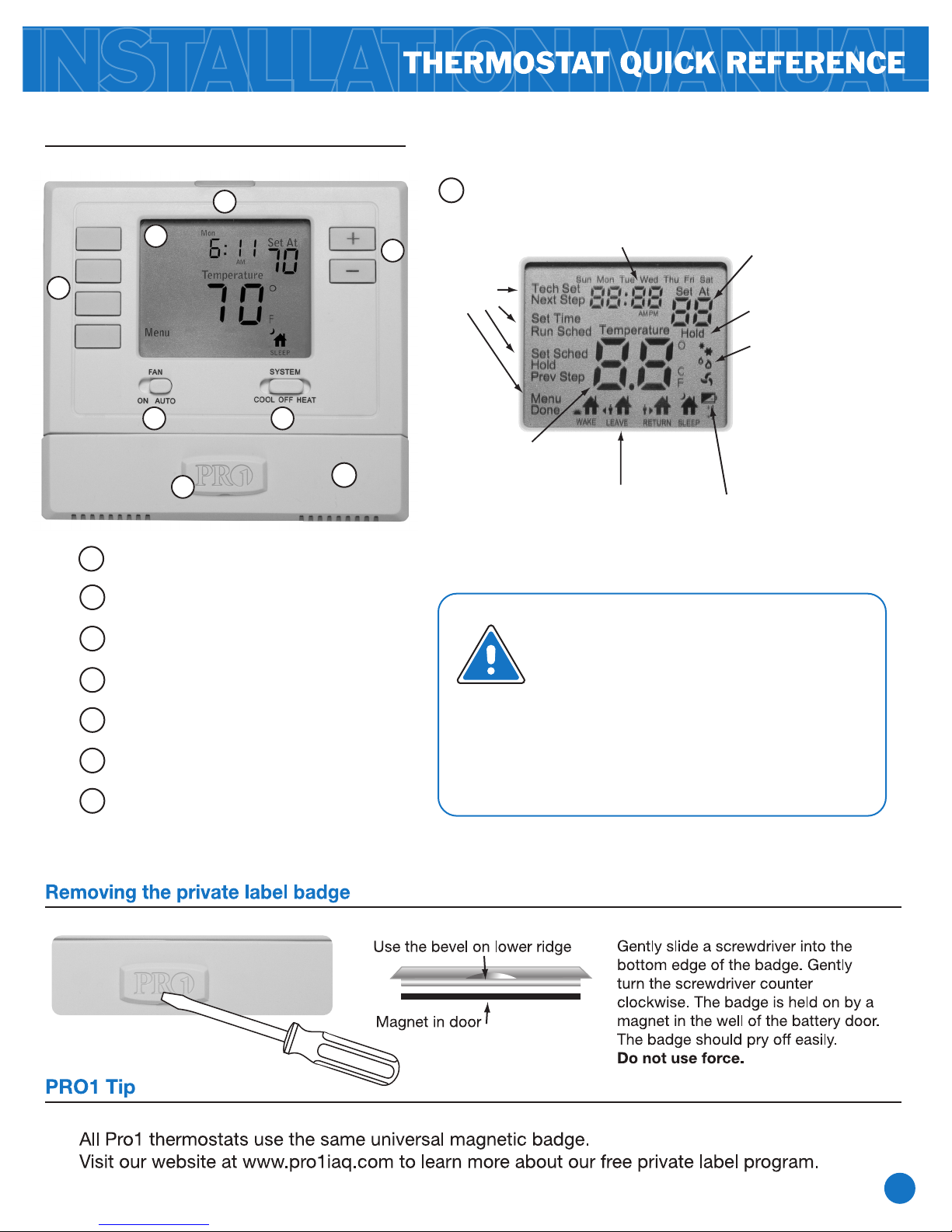
Getting to know your thermostat
2
1
7
3 4
8
2
Glow in the Dark Light Button
5
LCD
1
Days of the
week and time
6
Button
options
Indicates the current
room temperature.
Programmable Time
Period Icons: This thermostat
has 4 programmable time
periods per day.
Displays the user
selectable setpoint
temperature.
Hold is displayed when
thermostat program is
permanently overridden.
System operation
indicators: The COOL,
HEAT or FA N icon will
display when the COOL,
HEAT or FAN is on.
NOTE: The compressor
delay feature is active if
these icons are flashing.
The compressor will not
turn on until the 5 minute
delay has elapsed.
Low Battery Indicator:
Replace batteries when
indicator is shown.
Fan Switch
3
System Switch
4
Easy Change Battery Door
5
Setpoint Buttons
6
User Buttons
7
Universal Private Label Badge
8
Important:
The low battery indicator is displayed
when the AA battery power is low. If
the user fails to replace the battery
within 21 days, the thermostat
display will only show the low battery
indicator as a final warning before the
thermostat becomes inoperable.
3
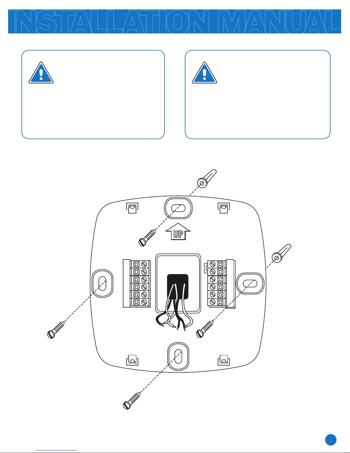
SUBBASE INSTALLATION
Caution:
Electrical Hazard
Failure to disconnect the
power before beginning to
install this product can cause
electrical shock or equipment
damage.
For vertical mount put
one screw top and one
screw bottom.
For horizontal mount put
one screw left and one
screw right.
Mercury Notice:
All of Pro1’s products are
mercury free. However, if the
product you are replacing
contains mercury, dispose of it
properly. Your local waste
management authority can give
you instructions on recycling
and proper disposal.
Vertical mount
Horizontal mount
UP
C
O
B
W
RH
RC
Horizontal mount
G
Y
Vertical mount
4
 Loading...