

Page 1
MultiLoad II & RCU II
DIVISION 2 (DIV2)
Installation Guide
(Part # 6074)
Page 2

DECEMBER 2018 TOPTECH SYSTEMS
Disclaimer
Toptech Systems assumes no responsibility for damages resulting from installation or use of its products. Toptech Systems will not be liable for any
claims of damage, lost data, or lost time as a result of using its products.
MultiLoad II & RCUII – Division 2 (DIV2)
Installation Guide
1124 Florida Central Parkway
Longwood, FL 32750
USA
Phone +1 (407).332.1774
Copyright Notice
Copyright © 2006 - 2018 Toptech Systems, Inc. All Rights Reserved.
The information contained in this document is proprietary and confidential. No part of this document may be copied, reproduced, or
transmitted in any medium without the express written permission of Toptech Systems, Inc.
MultiLoad II/ RCU II DIV-2 Installation Guide: 20181218 - Part # 6074
Page 3

EU Declaration of Conformity
Notified Body(ies)
NMi Certin B.V., Number 0122
Hugo de Grootplein 1
3314 EG Dordrecht
The Netherlands
The signatory, representing the manufacturer, declares that the products listed below are in conformity with the essential requirements of the
following EC Directive(s) when installed in accordance with the product installation instructions:
2014/32/EU The Measuring Instruments Directive (and its amending directives)
2014/30/EU The Electromagnetic Compatibility Directive (and its amending directives)
2014/34/EU The Potentially Explosive Atmospheres Directive (and its amending directives)
Product: Operator Interface/Process Control Equipment intended for use in potentially explosive atmospheres
Model name/number: MultiLoad II DIV2 (MID, YES), RCU II DIV2 (MID, NO)
Protective Systems: Nonincendive ‘ec ic’
Conformity has been demonstrated with reference to the following documentation:
(ATEX) EC test report for Project 06NK12831, Dated 2007-01-31
(MID) EC type-examination certificate TC7311
Compliance with the Essential Health and Safety Requirements has been assessed by reference to the following standards:
WELMEC guide 8.8 General and Administrative Aspects of the Voluntary System of Modular Evaluation of Measuring
Instruments under MID
OIML R117-1:2007(E) Dynamic measuring systems for liquids other than water
EN 61000-6-4: 2007 Generic emissions for industrial operating environments
EN 61000-6-2: 2005 Generic immunity for industrial operating environments
EN 60079-0: 2012 Explosive atmospheres Part 0: Equipment—General requirements
EN60079-7:2015 Explosive atmospheres – Part 7: Equipment protection by increased safety «e»
EN-60079-11: 2012 Explosive atmospheres Part 11: Equipment protection by intrinsic safety "i"
Year of CE Marking: 2007
Name: William J. Porthouse Position: Director of Engineering & Production Date: 20-December-2018
Name Plate
Page 4

Table of Contents
Overview ........................................................................................................................... 1
Chapter 1 General information & Warnings ............................................................ 3
Receiving and/or Returning Equipment ............................................................. 3 1.1
Safety Warnings ................................................................................................ 4 1.2
Electrostatic Discharge (ESD) Protection ................................ ........................... 5 1.3
FCC Note .......................................................................................................... 6 1.4
Chapter 2 Operating conditions and components ................................................... 7
Product Outline and dimensions ........................................................................ 7 2.1
MultiLoadII/ RCUII – DIV2 model - Picture .................................................. 7 2.1.1
MultiLoadII/ RCUII – DIV2 model – Dimensions .......................................... 8 2.1.2
2.1.2.1 Front View ................................................................................................ 8
2.1.2.2 Back View ................................................................................................ 9
2.1.2.3 Bottom View ........................................................................................... 10
2.1.2.4 Side View ............................................................................................... 11
Operating Characteristics: ............................................................................... 12 2.2
Chapter 3 Installing the MultiLoad II/RCUII DIV2 .................................................. 14
Tools Required ................................................................................................ 14 3.1
Installation ................................................................................................ 14 3.1.1
Servicing and Repair................................................................................. 14 3.1.2
Cover Closure and Bolt Replacement .............................................................. 14 3.2
Cable Entries .................................................................................................. 14 3.3
Mounting the MultiLoad II/ RCU II DIV-2 Enclosure: ........................................ 14 3.4
Drywall ...................................................................................................... 15 3.4.1
Wood ........................................................................................................ 15 3.4.2
Concrete or Cinder Block Walls ................................................................ 15 3.4.3
Mounting Height Considerations ............................................................... 15 3.4.4
Recommended Wire Sizes And Torque For All Terminal Blocks ...................... 17 3.5
Electrical Supply Connections ......................................................................... 17 3.6
AC Powered Models ................................................................................. 18 3.6.1
DC Powered Models ................................................................................. 18 3.6.2
Equipment Grounding ............................................................................... 19 3.6.3
Page 5

Chapter 4 Data Communications Interface ........................................................... 20
Available Communications Protocol Selection and Wire spec .......................... 21 4.1
RS-422/485 .............................................................................................. 21 4.1.1
RS-232 ..................................................................................................... 21 4.1.2
Ethernet .................................................................................................... 22 4.1.3
Communication Connection Wiring .................................................................. 22 4.2
FCM I / FCM II Communications ( MultiLoad II Product Only) - COM 0 –4.2.1
Port – RS485 ....................................................................................................... 22
Host/TMS Communications ...................................................................... 23 4.2.2
4.2.2.1 COM 1 - RS-485 4-wire - Host/TMS Communications ............................ 23
4.2.2.2 COM 1 - RS-485 2-wire : Host/TMS Communications ............................ 24
4.2.2.3 COM 1 - RS-232 - Host/TMS Communications ...................................... 25
4.2.2.4 Ethernet – Host/TMS Communications .................................................. 26
Host Ticket Printer/Data Logger ................................................................ 27 4.2.3
4.2.3.1 COM2 – RS232 - Host Ticket Printer/Data Logger ................................. 27
Chapter 5 Connecting Field devices to the I/O Board .......................................... 30
Where to find the internal I/O board ................................................................. 30 5.1
Available I/O points per board .......................................................................... 31 5.2
Terminal arrangements per board .................................................................... 33 5.3
Digital Analog I/O board (IO_DA) ............................................................. 33 5.3.1
2 Meter I/O board ( IO-2M)........................................................................ 34 5.3.2
How to connect and wire field devices to the I/O boards .................................. 35 5.4
MultiLoad II Flow Meter and Control Valve Wiring ..................................... 36 5.4.1
MultiLoad II Additive Wiring: Outputs ........................................................ 37 5.4.2
MultiLoad II Additive Wiring: Inputs ........................................................... 38 5.4.3
MultiLoad II Analog Wiring ........................................................................ 39 5.4.4
5.4.4.1 RTD Wiring ............................................................................................ 39
5.4.4.2 MultiLoad II 4 – 20 mA Wiring ............................................................... 40
MultiLoad II AC Output Wiring ................................................................... 41 5.4.5
MultiLoad II AC Input Wiring ..................................................................... 42 5.4.6
MultiLoad II DC Permissive/Status Wiring ................................................. 43 5.4.7
MultiLoad II DC Output Wiring .................................................................. 44 5.4.8
MultiLoad II 2 Output Air Eliminator Wiring ................................................ 45 5.4.9
MultiLoad II Lectro Count Remote Display Wiring ................................... 46 5.4.10
RCU II DC Input Wiring ........................................................................... 47 5.4.11
RCU II AC Output Wiring ........................................................................ 48 5.4.12
Page 6

RCU II DC Output Wiring ........................................................................ 49 5.4.13
Typical 1 meter application wiring example IP&E Drawing (electrical wiring 5.4.14
schedule) ............................................................................................................. 50
Chapter 6 Configurations ..................................................................................... 51
Switch Access Control ..................................................................................... 51 6.1
External Switch Access Control (MultiLoad II Only) .................................. 51 6.1.1
External Type 1 Program / W&M switches ................................................ 52 6.1.2
External Type 2 Program / W&M switches ................................................ 52 6.1.3
External Type 3 Program / W&M switches ................................................ 54 6.1.4
Internal Switch Access Control ................................................................. 54 6.1.5
MultiLoad II/ RCU II DIV-2 Keypad .................................................................. 56 6.2
Menus and Screens ......................................................................................... 57 6.3
Field Modification and Data Entry .................................................................... 58 6.4
MultiLoad II/ RCU II Preliminary Configuration ................................................. 59 6.5
Verify Communications Between MultiLoad II/ RCU II And I/O Board .............. 62 6.6
Using I/O Diagnostics ...................................................................................... 63 6.7
Chapter 7 Service and Repair .............................................................................. 65
Overview and Subassemblies .......................................................................... 65 7.1
CPU Subassembly Removal and Replacement: .............................................. 67 7.2
Display Subassembly Removal and Replacement: .......................................... 69
7.3
Flat Display Cable connector : Remove and Connect .............................. 69 7.3.1
Keypad Removal and Replacement: ................................................................ 70 7.4
Card Reader Removal and Replacement ........................................................ 71 7.5
Slotted Card Holder Mounted Prox Reader Removal and Replacement: 7.5.1
(Current Model) ................................................................................................ ... 71
Bracket Mounted (Obsolete) Prox Reader Removal and Replacement: .... 72 7.5.2
Slotted Card Holder Mounted Prox Reader HID (Obsolete) Removal and 7.5.3
Replacement: ...................................................................................................... 73
Slotted Card Holder Mounted TWIC Reader (Obsolete) Removal and 7.5.4
Replacement: ...................................................................................................... 74
W&M switch assembly Removal and Replacement ......................................... 75 7.6
Ice Shield Removal and Replacement: ............................................................ 76 7.7
Overview Parts List and Partnumbers : ............................................................ 77 7.8
Chapter 8 Hardware Revision History & Compatibilty.......................................... 79
Chapter 9 Revision History .................................................................................. 80
Page 7

Hardware Revision .......................................................................................... 80 9.1
Manual Revision .............................................................................................. 81 9.2
Page 8

Table of Figures
Figure 2.1 MultiLoad II (ML II) / Remote Control Unit II (RCU II) Division 2 Unit ............ 7
Figure 2.2 Unit Outline Drawing – Front View ....................................................................... 8
Figure 2.3 Unit Outline Drawing – Back View ....................................................................... 9
Figure 2.4 Unit Outline Drawing – Bottom View -2 Hole Base ......................................... 10
Figure 2.5 Unit Outline Drawing – Bottom View - 5 Hole Base ........................................ 10
Figure 2.6 Unit Outline Drawing – Side View ...................................................................... 11
Figure 3.1 Suggested Mounting Position ............................................................................. 16
Figure 3.2 Screen Visible Area .............................................................................................. 16
Figure 3.3 MultiLoad II/ RCU II AC Power Supply/Comm Board ..................................... 18
Figure 3.4 DC Power Connections ....................................................................................... 19
Figure 4.1 FCM / PCM Connections ..................................................................................... 23
Figure 4.2 RS485 4-Wire, Host to a Single MultiLoad II/ RCU II (recommended) ........ 23
Figure 4.3 RS485 4-Wire, Host to Multiple MultiLoad II/ RCU IIs .................................... 24
Figure 4.4 RS485 2-Wire, Host to a Single MultiLoad II/ RCU II...................................... 24
Figure 4.5 RS485 4-Wire, Host to Multiple MultiLoad II/ RCU IIs .................................... 25
Figure 4.6 RS232, Host to a Single MultiLoad II/ RCU II .................................................. 25
Figure 4.7 RS232, Host to Multiple MultiLoad II/ RCU IIs ................................................. 26
Figure 4.8 Ethernet Connections .......................................................................................... 26
Figure 4.9 Ticket Printer / Data Logger Connections with Handshake ........................... 27
Figure 4.10 Ticket Printer / Data Logger Connections without Handshake ..................... 28
Figure 4.11 PTB Printer Connection with Handshake......................................................... 28
Figure 5.2 2 Meter I/O Board Terminal Block Assignments .............................................. 34
Figure 6.1 Type 1 Program / W&M Switches ...................................................................... 52
Figure 6.2 Type 2 Program / W&M Switches ...................................................................... 52
Figure 6.3 Type 3 Program / W&M Switch with Magnetic Bolts ....................................... 54
Figure 6.4 CPU DIP Switches for Program and W&M Access (rev 1.0) ......................... 56
Figure 6.5 CPU DIP Switches for Program and W&M Access (rev 2.0) Field Switch Access Control
(MultiLoad II Only) ....................................................................................................................... 56
Figure 7.1 MultiLoad II (ML II) / Remote Control Unit II (RCU II) Division 2 Unit .......... 65
Page 9

Figure 7.2 ML II/ RCU II Div2 Unit Assembly Slotted Card Holder with MT11 .............. 66
Figure 7.3 CPU Board, Power Supply / Comm Board, I/O Board with Chassis ............ 67
Figure 7.4 ML II/ RCU II Div2 Unit Cover Display Assembly ............................................ 69
Figure 7-5 Cam lock in the Open (Up) position Figure 7-6 Cam lock in the closed (down) 70
Figure 7-7 Display Cable Insertion ........................................................................................ 70
Figure 7.8 ML II/ RCU II Div2 Unit Cover Keypad Assembly ............................................ 71
Figure 7.9 Exploded View Front Cover Assembly: Slotted Card Holder with MT11 ..... 72
Figure 7.10 ML II/ RCU II Div2 Cover Assembly Prox Bracket Mount Thinline II (Obsolete) 73
Figure 7.11 ML II/ RCU II Div2 Cover with Slotted Card Holder Thinline II (Obsolete) .. 74
Figure 7.12 ML II/ RCU II Div2 Unit Assembly Prox/TWIC Slotted Card Holder RP15 (Obsolete)
75
Figure 7.13 ML II/ RCU II DIV2 W&M Assembly .................................................................. 76
Figure 7.14 Ice Shield Assembly Installation Slotted Card Holder .................................... 77
Page 10

Chapter
Topics Covered
1.General Information and
Warnings
This chapter reviews safety and compliance information, as well as
instructions for receiving and returning products.
2.Operating Conditions &
Components
This chapter covers product outline and dimensions, as well as operating
characteristics of the unit.
3.Installing the MultiLoad II/RCUII –
DIV2
This chapter covers installation considerations and instructions for the
Division 2 (DIV2) Model.
4.Data Communication Interface
This chapter reviews hardware connections and communication
processes.
5.Connecting Field Devices to the
Internal I/O Board
This chapter covers the available I/O points per board, the terminal
arrangements per board, and then describes in detail how to connect
different field devices to the internal I/O Boards.
6. Configurations
This chapter describes how to navigate the system, select field
values, perform data entry, and toggle options on and off.
7. Service and Repair
This chapter describes how to service and repair the MultiLoad/
RCUII DIV-2 subassemblies and parts.
8. Hardware Revision History &
Compatibility
This chapter provides changes, modifications, and updates to the
hardware.
9. Revision History
This chapter provides further hardware revisions as well as revisions
made to this document.
Overview
This document is designed to guide individuals installing MultiLoad II/ RCU II DIV2 equipment, engineering
firms developing site electrical drawings, and users troubleshooting system operations such as managers,
system administrators, technicians, and meter proving personnel.
The following table provides an informative summary of the material available in this guide:
1
Page 11

ICON KEY
Important information to enhance understanding and make better use of the product.
Indicates potential damage to hardware or loss of data.
Potential for property damage or that personal injury may occur. Pay close attention and
follow instructions when this symbol is displayed.
The following keys allow the user to locate information needed in this guide:
Typographical Conventions:
Boldface: Indicates what is pressed on the keypad. Example: Key in 00000.
Italics: Emphasizes a key product or industry term.
Example: the display features a pick-list style of item selection.
This guide covers RCU/MultiLoad DIV2 installation information only. For information about base MultiLoad
firmware, please consult the MultiLoad II User Guide. For information about wiring other models, please
consult the respective installation guides. For information about the MultiLoad register interface and Modbus
communication, please reference the MultiLoad II Communication Guide. Updated versions of all manuals,
including this one, are available on our website at http://www.toptech.com.
2
Page 12

Chapter
1
Chapter 1 General Information & Warnings
Receiving and/or Returning Equipment 1.1
At receipt, the MultiLoad II/ RCU II should be immediately inspected after opening the packaging case.
If any damage is visible, notify the carrier at once to establish liability.
Contact Toptech’s Return Materials Department to initiate timely repair or replacement of the unit.
A Return Materials Authorization (RMA) will be for the purpose of returning the product or parts
requiring repair. Do not return any material to Toptech without an RMA.
Contact Information for Americas:
Return Materials Department
Toptech Systems, Inc.
1124 Florida Central Pkwy
Longwood, FL 32750 USA
+1 (407) 332-1774
Contact Information for EMEA and Asia:
Return Materials Department
Toptech System NVs
Nieuwe weg 1- haven 1053
2070 Zwijndrecht, BELGIUM
+32 (0)3 250 60 60
Prior to installation, the MultiLoad II/ RCU II should be stored in its packing case and be protected from
damage due to handling and adverse weather conditions.
3
Page 13

Safety Warnings 1.2
NORTH AMERICAN INSTALLATIONS:
▲ This equipment is suitable for use in Class I, Division 2, Groups C and D locations, OR non-
hazardous locations.
▲ WARNING: EXPLOSION HAZARD. Do not disconnect equipment unless power has been
removed or the area is known to be non-hazardous.
▲ WARNING: EXPLOSION HAZARD. Substitution of components may impair suitability for
Class I, Division 2.
▲ WARNING: EXPLOSION HAZARD. The area must be known to be non-hazardous before
servicing/replacing the unit and before installing.
▲ CAUTION: Battery may explode if mistreated. DO NOT RECHARGE, DISASSEMBLE, OR
DISPOSE OF IN FIRE.
▲ CAUTION: Field wiring must have a temperature rating of 75 °C or greater.
▲ A battery is soldered to the processor board for retention of data, time, and date. This battery
should last more than ten years. Please return the board to Toptech Systems for battery
replacement. This battery must be replaced with Matsushita Electric, model BR2477A
only. Use of another battery may present a risk of fire or explosion.
▲ The installation of this product must be in conformity with NFPA 70 (US National Electric Code)
or CSA C22.1 (Canadian Electrical Code) as appropriate.
INSTALLATIONS NORD-AMÉRICAINES (FRANÇAIS)
▲ Cet équipement est compatible pour une installation en Classe I, Division 2, Groupes C & D ou
les emplacements non dangereux..
▲ AVERTISSEMENT: RISQUE D'EXPLOSION. Avant de déconnecter l’ équipement, couper
le courant ou s’assurer que l’emplacement est designe non dangereux.
▲ AVERTISSEMENT: RISQUE D'EXPLOSION. La substitution de composants peut render
ce materiel inacceptable pour les emplacements de Classe I, Division 2.
▲ AVERTISSEMENT: RISQUE D'EXPLOSION. Avant réparer ou remplacer l’équipement et
avant d’installer s’assurer que l’emplacement est designe non dangereux.
▲ PRUDENCE: La pile peut exploser si elle est maltraitée. NE PAS RECHARGER, NE PAS
DÉMONTER, ET NE PAS JETER DANS LE FEU.
▲ PRUDENCE: Câblage de terrain doit avoir un classement de température de +75 °C ou
plus.
▲ Une pile est soudée à la carte processeur pour la conservation des données, de l'heure, et de la
date. Cette pile devrait durer pendant plus que dix ans. Veuillez retourner la carte processeur à
Toptech Systems pour le remplacement de la pile. Remplacez la pile avec Matsushita
Electric, modèle BR2477A seulement. Utiliser une autre pile peut présenter un risque
d'incendie ou d'explosion.
▲ L’installation de ce produit doit se conformer avec le Code National d'Électricité, NFPA 70 ou le
Code Canadien d'Électricité, CSA C22.1 comme appropriée.
4
Page 14

ATEX AND IECEX INSTALLATIONS:
▲ This equipment is suitable for use in EX Zone 2 Group IIB Locations, OR non-hazardous
locations.
▲ WARNING: Do not open when an explosive atmosphere may be present.
▲ WARNING: Do not disconnect equipment unless power has been removed or the area is
known to be non-hazardous.
▲ WARNING: EXPLOSION HAZARD. The area must be known to be non-hazardous before
servicing/replacing the unit and before installing.
▲ CAUTION: Battery may explode if mistreated. DO NOT RECHARGE, DISASSEMBLE, OR
DISPOSE OF IN FIRE.
▲ CAUTION: Field wiring must have a temperature rating of 75 °C or greater.
▲ A battery is soldered to the processor board for retention of data, time, and date. This battery
should last more than ten years. Please return the board to Toptech Systems for battery
replacement. This battery must be replaced with Matsushita Electric, Model BR2477A
only. Use of another battery may present a risk of fire or explosion.
▲ The installation of this product must be in conformity with IEC/EN 60079-14.
Electrostatic Discharge (ESD) Protection 1.3
The MultiLoad II/ RCU II contains electronic components and assemblies subject to damage by ESD.
The MultiLoad II/ RCU II was designed to protect against ESD while the unit is closed and in normal
operation. Proper handling procedures must be observed during the removal, installation, repair and
other handling of printed circuit board assemblies, electronic devices and components. This includes:
1) Service to be performed by authorized personnel only.
2) The person performing the service must be grounded by an ESD grounding strap and
connected to ground.
3) While performing maintenance or repair, touch an unpainted metal of the MultiLoad II/ RCU
II surface prior to touching or handling any printed circuit boards or electronic components.
4) Printed circuit board assemblies must be placed in and transported in conductive bags or
other conductive containers.
5) Printed circuit boards must not be removed from the conductive container until time of use.
6) All other “best” practices for protecting devices from ESD must be observed.
5
Page 15

FCC Note 1.4
This equipment complies with the limits for a Class A Digital Device, pursuant to part 15 of the FCC
Rules. These limits are designed to provide reasonable protection against harmful interference when
the equipment is operated in a commercial environment. This equipment generates, uses, and can
radiate radio frequency energy and, if not installed and used in accordance with the instruction manual,
may cause harmful interference to radio communications. Operation of this equipment in a residential
area is likely to cause harmful interference in which case the user will be required to correct the
interference at theirexpense.
Modifications not approved by the manufacturer could void the user's authority to operate the
equipment under FCC rules.
6
Page 16

Chapter
2
Chapter 2 Operating Conditions and Components
Product Outline and dimensions 2.1
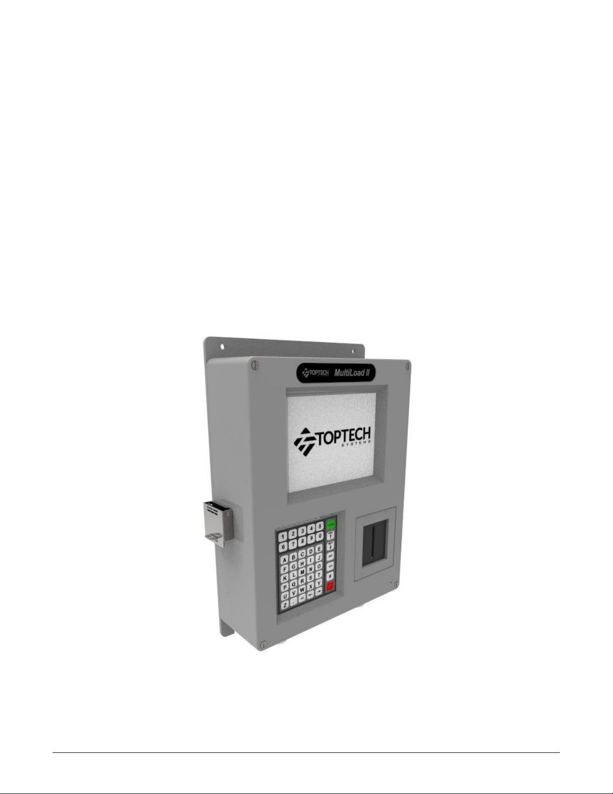
MultiLoad II/ RCU II – DIV2 Model - Picture
2.1.1
Figure 2.1 MultiLoad II (ML II) / Remote Control Unit II (RCU II) Division 2 Unit
7
Page 17
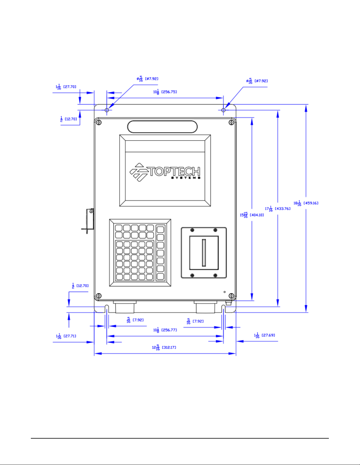
MultiLoad II/ RCU II – DIV2 Model – Dimensions
2.1.2
The dimensions in this section are indicated in inches and millimeters (in parenthesis).
2.1.2.1 Front View
Figure 2.2 Unit Outline Drawing – Front View
8
Page 18
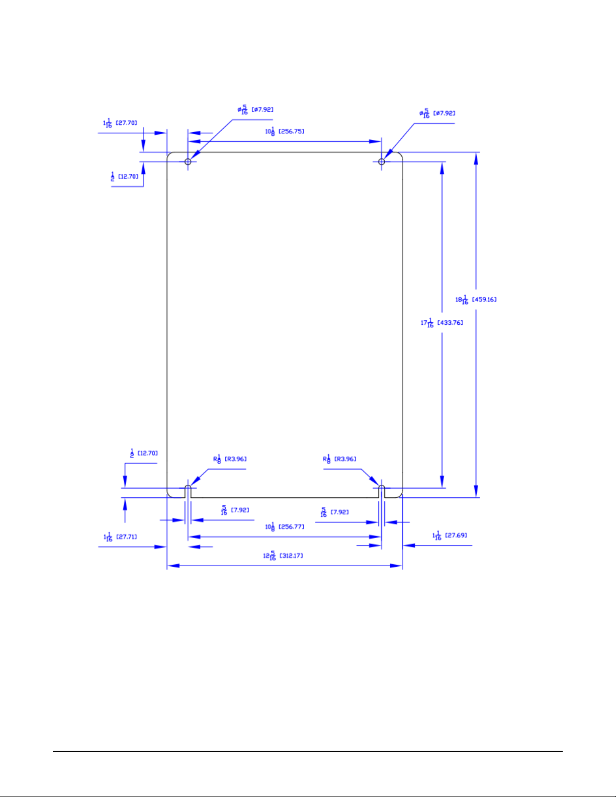
RCUII/ ML II Div 2
MOUNTING TEMPLATE
2.1.2.2 Back View
Figure 2.3 Unit Outline Drawing – Back View
9
Page 19
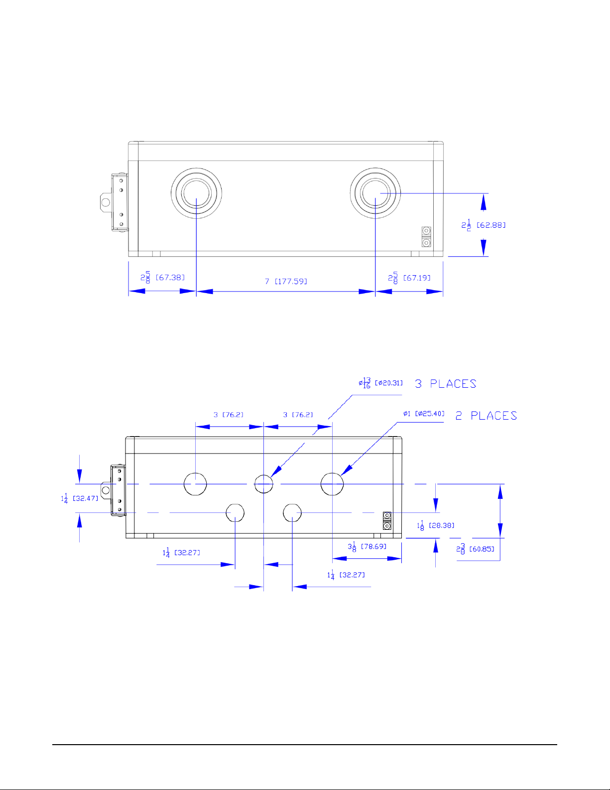
2.1.2.3 Bottom View
2.1.2.3.1 2- Hole Base
2 x 1” NTP Aluminum HUBS
Figure 2.4 Unit Outline Drawing – Bottom View -2 Hole Base
2.1.2.3.2 5- Hole Base (Europe)
3xM20 and 2xM25
Figure 2.5 Unit Outline Drawing – Bottom View - 5 Hole Base
10
Page 20
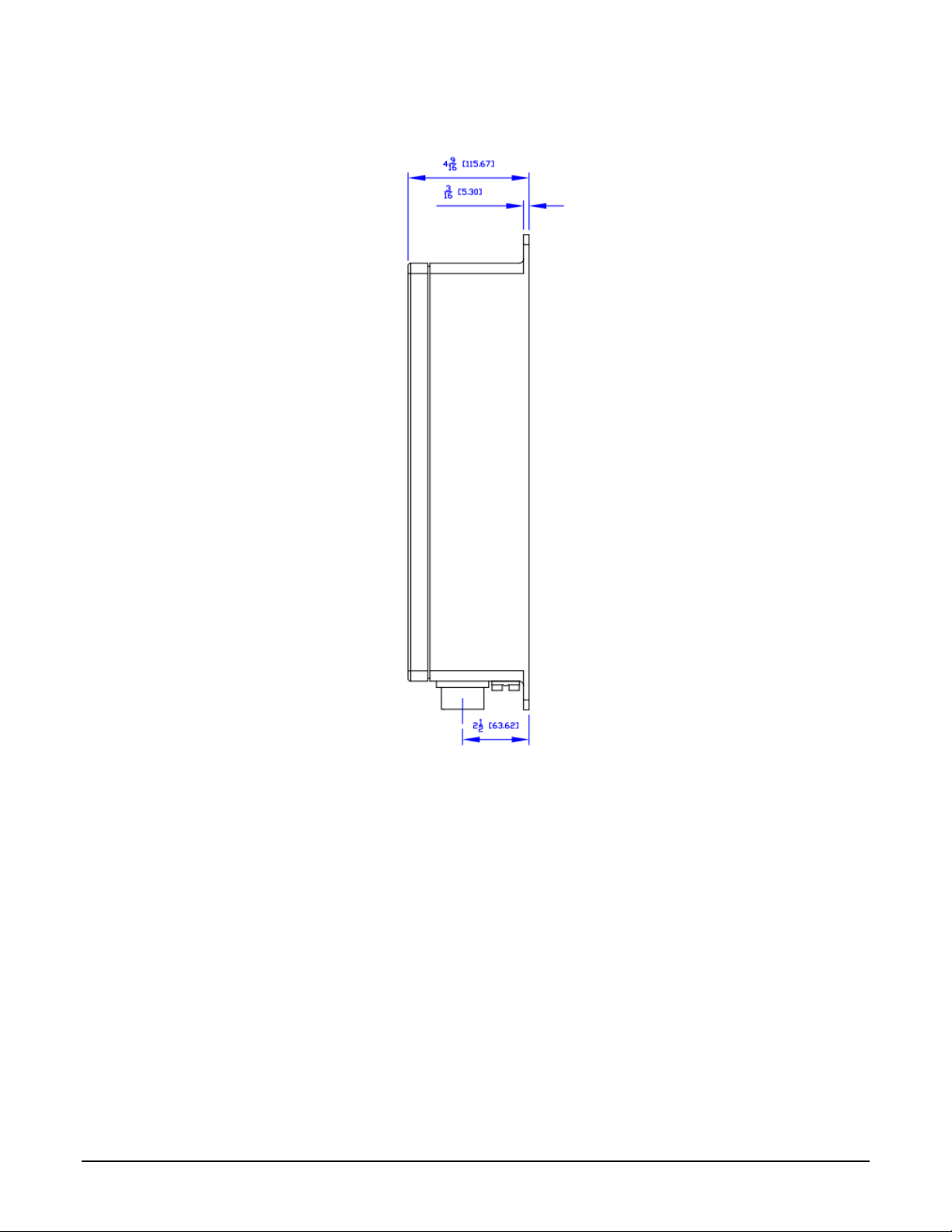
2.1.2.4 Side View
Figure 2.6 Unit Outline Drawing – Side View
11
Page 21

Characteristics
Description
Operating Voltage
85 - 250 Vac, 47-63 Hz, 300 – 150 mA
Voltage Option
9 - 30 Vdc, 600mA
Operating Temperature
40°F to 140°F: -40°C to 60°C
Enclosure
Type 4, IP65
ETL Listed (US, Canada) Class 1, Division 2, Groups C & D, T4
Weight
24 lbs : 11 kg
Display
Color 8.4” Diagonal VGA
Prox Card Reader
Captive or Non-captive: supports TWIC
Lockable External W&M Bolts
Program Access, Weights & Measures Parameter Access (on MultiLoad
only)
Keypad
47 Key Alpha/ Numeric Membrane Switch Keypad
Communications
3 serial ports (1 RS-485, 2 User Selectable RS-232 or RS-485)
1 Ethernet port 10/100 Mbps
Type I/O
Digital/ Analog I/O
Quantity, Location
2 Meter I/O Quantity,
Location
Electrical Rating
AC Outputs:
5 (TB1)
8 (TB2, TB3)
12 - 250 Vac rms, 500 mA (per point), TB1
AC Inputs
0
2 (TB1)
90 - 250Vac
DC Outputs:
3 (TB3)
2 (TB9)
0 - 30 Vdc, 600 mA (per point), TB3
DC Inputs:
5 (TB2-Right)
(2 High Speed)
6 (TB7, TB8)
(4 High Speed)
5 - 30Vdc, TB2B
Dual Channel flow meter inputs (1-5000Hz)
Miscellaneous signal inputs
12Vdc Source:
167mA Max Load
(TB2-Left)
250mA Max Load
(TB6)
Isolated Power Supply
Power for flow meter pulsers or preamps
RTD Input:
1 (TB4)
2 (TB4, TB5)
100-ohm platinum, four wire
Coefficient 0.00385 Ohm/Ohm/°C
Analog Input
1 (TB5)
0
4 - 20mA, 1.5V maximum burden
Analog Output
1 (TB6)
0
4 - 20mA, Requires 12Vdc – 30Vdc Supply
Operating Characteristics 2.2
The Remote Control Unit – Division 2 (DIV2) Model has the following characteristics:
Internal I/O Options: Two versions of an optional internal I/O board are available:
- the Digital/ Analog I/O board.
- the 2 Meter I/O board.
The quantity and electrical ratings of each I/O are described in the table below:
12
Page 22
I/O TYPE
Voltage
Freq
Dissipation
per Point
Digital/ Analog I/O
2 Meter I/O
# I/O
TOTAL
Dissipation
# I/O
TOTAL
Dissipation
[V]
[Hz]
[W] [W]
[W]
ACOUT
230
50
0.36 5 1.78
8
2.85
120
60
0.32 5 1.62
8
2.60
ACIN
230
50
0.73 0 2 1.46
120
60
0.44 0 2 0.89
DCOUT
5
--
0.02 3 0.07
2
0.05
12
--
0.02 3 0.07
2
0.05
24
--
0.02 3 0.07
2
0.05
30
--
0.02 3 0.07
2
0.05
DCIN
5
--
0.00 6 0.03
6
0.03
15
--
0.06 6 0.33
6
0.33
24
--
0.16 6 0.97
6
0.97
30
--
0.23 6 1.41
6
1.41
4-20 mA Input
--
--
0.03 1 0.03
0
--
Internal I/O Heat Dissipation:
*I/O points dissipating 1 mW or less are not reported
13
Page 23

Chapter
3
Chapter 3 Installing the MultiLoad II/RCUII DIV2
Tools Required 3.1
Installation
3.1.1
- ¼” Flat Head screw driver is required for tightening cover screws.
Servicing and Repair
3.1.2
- #2 Philips screwdriver for circuit board removal.
- ¼” socket wrench for CPU circuit board removal and a 5/16” socket wrench for display board
removal.
- #2 Philips screwdriver for removal of keypad plat screws.
Cover Closure and Bolt Replacement 3.2
When closing the cover, gently lift on the bottom of the cover when in position for starting one or two of
the right corner screws. This is done to assist the alignment of the cover and base holes for starting the
screws. The enclosure cover is secured to the housing by four 6mm slotted/Philips screws. When the
screws are removed, the front cover will swing left and hang from its hinges. The screws are captive
and will remain with the cover.
Cable Entries 3.3
Two 1” NPT conduit hubs are provided for the installation of conduit and cables.
No hubs are provided with the 5 hole base.
Mounting the MultiLoad II/ RCU II DIV-2 Enclosure 3.4
The DIV-2 enclosure should be located in a shaded area. Direct sunlight can increase internal
temperature to greater than 140°F or 60°C.
14
Page 24

Exterior dimensions of the standard MultiLoad II/ RCU II DIV-2 enclosure are shown in Figures 2.2 –
2.6. There is only one mounting orientation possible; reference Figure 2.2 for the MultiLoad II/ RCU II
DIV-2 Mounting Template. The cable entries are located at the bottom of the unit.
Appropriate fasteners must be selected to support the minimum weight of 24 lbs (11 kg). Toptech
offers the following mounting suggestions for three typical surfaces: drywall, wood, or concrete/cinder
block.
Drywall
3.4.1
Insert four fasteners through the corner mounting holes, shown in Figure 2.2. For the fasteners, use #14 x 1
¾” (M6 x 40 mm) Phillips pan head sheet metal screws inserted in #14 (M6) self-tapping nylon anchors.
Place one #14, 3/8” OD (M6, 10 mm 0D) flat washer under the head of the screw before inserting the screw
into the mounting hole.
Wood
3.4.2
Follow the instructions above for Drywall installation, substituting the #14 x 1¾” (M6 x 40 mm) wood screws
for the four sheet metal screws. Do not use the self-tapping nylon inserts.
Concrete or Cinder Block Walls
3.4.3
Follow the instructions above for Drywall installation, substituting the a 1/4 ” x1 3/4” Tapcon masonry fastener
for the four sheet metal screws. Do not use the self-tapping nylon inserts.
Drill pilot holes for the Tapcons using a 3/16” x 3 ½” masonry drill bit.
Mounting Height Considerations
3.4.4
When mounting the enclosure, be aware of the limitations that the cover places on screen visibility.
Because the display is inset about an inch [25mm] from the surface of Div-2 and SMP units and the
screen is inset an inch-and-one-half [39mm] in the EXL unit, the enclosure should be mounted so that
top of the screen’s visible area is at eye level of the tallest operator. Figure 3.1 shows the visible area
at arm’s length and the distance from the ground to the top mounting hole location for a six-foot [1.8m]
tall user. Figure 3.2 shows the offset of the top of the screen’s visible area from the top mounting bolt
and the depth of the screen within the unit.
15
Page 25
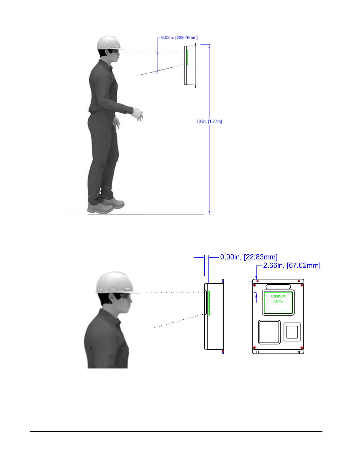
Figure 3.1 Suggested Mounting Position
Figure 3.2 Screen Visible Area
16
Page 26

Recommended Wire Sizes and Torque for All Terminal Blocks 3.5
Three sizes of terminal blocks are used in the MultiLoad II/ RCU II products: 7.62 mm pitch (supply
power), 5.08 mm pitch (line voltage switching), and 3.81 mm pitch (serial communication, analog or dc
voltages). The 7.62 and 5.08 mm terminal blocks have an allowable wire size of 24 AWG – 12 AWG
and should be tightened to 0.55 Nm +/-0.05 Nm (5 lb in +/- 0.4 lb in).
The 3.81 mm terminal blocks have an allowable wire size of 28 AWG – 16 AWG and should be
tightened to 0.23 Nm +/-0.02 Nm (2 lb in +/- 0.2 lb in).
Electrical Supply Connections 3.6
The MultiLoad II/ RCU II may be equipped for either 85 -250Vac or 24Vdc operation. Verify the
power type before making any connections.
Fiel Wiring must be rated 75°C or greater.
WARNING: If there are unused holes, blanking elements appropriate for the type enclosure
must be used.
Do not route AC and DC wiring in the same conduit.
All wiring must enter the MultiLoad II/ RCU II enclosure through conduit via entries in the bottom of the
enclosure. All conduits must be terminated at the enclosure by use of appropriately-rated conduit hubs
or glands.
Wires must be stripped ¼” and fully inserted into terminal block with no bare conductor exposed.
Review section 3.5 for recommended wire size and torque values.
Both ac and dc input models require a safety ground connection as described in section 3.6.3 below.
A service loop is recommended for all wires and cables entering the enclosure.
Do not allow service loop cables to overlap the circuit boards. Coil any cable length in the
bottom of the enclosure. Keep AC wiring separated from all other wiring in the enclosure by use
of the supplied partitions (see wire partition instructions below).
Wiring must comply with all local electrical codes.
17
Page 27
AC Powered Models
3.6.1
Provide over current protection using a 15 Amp circuit breaker or equivalent. The breaker also serves
as a means of disconnection from the operating supply as required by UL/ISA/IEC 61010-1 and
CAN/CSA-C22.2 NO. 61010-1. The disconnected device may not be blocked or be made difficult to
operate by the MultiLoad II/ RCU II or any other device. Note that installation of disconnects are
typically prohibited in Class I, Division 2 locations.
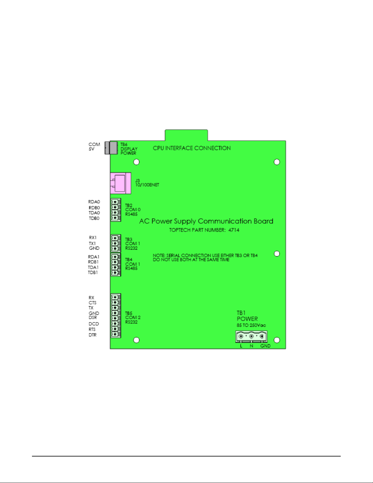
Power required: 85 – 250 Vac, 47 – 63 Hz, 300 mA @ 85Vac/ 150 mA @250Vac. The power
connector is located in the right hand, bottom corner of the Power Supply/Communication board as
shown in figure 3.3. Select supply wire rated 300V or better with a flammability rating of at least VW-1.
Figure 3.3 MultiLoad II/ RCU II AC Power Supply/Comm Board
DC Powered Models
3.6.2
The MultiLoad II/ and RCU II is optionally available with a 24 Vdc power supply. The power source
used to supply the MutliLoad II/RCUII must be rated 9 – 30 Vdc SELV, Limited Energy (Class 2). The
rated supply input current is 600mA. The supply should be protected by a 1.5 Amp fuse.
18
Page 28
Wire gauge (AWG)
Distance (feet)
24
50
22
100
20
150
18
250
16
400
Do not connect the power supply dc common to earth ground.
The 3-position terminal block is located in the right hand corner of the power supply/communication
board.
Figure 3.4 DC Power Connections
Equipment Grounding
3.6.3
A safety ground should be attached to terminal block TB1 (on both ac and dc input power models) to
maintain electrical safety in the event of a fault condition. Follow the terminal block wiring instructions
in section 3.6. Keep the required tightening torque in mind (section 3.5).
Wiring guidelines for using 24 Vdc power
supply:
The external ground connection is not provided for the attachment of the protective conductor (the
safety ground). Rather, it is provided only as a supplemental bonding connection where local
authorities permit or require such a connection: for example, as a means of equipotentiality. The wire
connection is on the bottom right exterior surface. The following wire sizes may be used: 10 AWG
(5.26 mm2) or 11 AWG (4.17 mm2).
19
Page 29

Communication
Port
Interface Type
Typical Function
Terminal (Figure 3.3)
Comm. Port 0
RS-485
Internal I/O board /
TB2
FCM I / FCM II / PCM
Communication
Comm. Port 1
RS-232 or RS-485
Host Communication (TMS) /
Printer
TB3 RS-232
TB4 RS-485
Comm. Port 2
RS-232 or RS-485 (2 wire)
Ticket Printer/Data Logger
TB5
Ethernet
10/100MBPS
Host Communication (TMS)
J3
Cat 5 (or
higher)Cable
If a service loop is used, the maximum wire length in the service loop should not exceed
3 inches [75mm].
Separate AC and DC wiring by at least 3 inches [75mm]. Do not allow excess wire in the
service loop to overhang printed circuit board.
Default settings in MultiLoad are: COM O – FCM ; COM 1- HOST , and COM2 – NA.See
the user guide for more details
Only one port may be defined as an FCM, Print or Alibi Log, otherwise, a ‘Port Usage
Conflict(s)’ message will display upon re-boot. See the user guide for more details
Chapter
4
Chapter 4 Data Communications Interface
The MultiLoad II/ RCU II has four (4) communications ports (see Figure3.3), each with a specific
purpose. The following section provides the information required to select and make the wiring
connections to the ports:
20
Page 30

Although a ground wire is not required, the common mode voltage between the MultiLoad
II/ RCU II and the field device must be within -7Vdc to 12Vdc. To correct situations
where this is not the case, the DC common is available on COM 0 and COM 1 by using
TB2, pin five (revision 1.1 Power Supply/Comm boards only) and TB 3, pin three.
Connect the MultiLoad II/ RCU II DC common to the signal ground of the field device.
Available Communications Protocol Selection and Wire Spec 4.1
This section describes the available communication protocols for MultiLoadII/RCU II.
RS-422/485
4.1.1
The RS-422/485 communications protocol is designed for multi-point (i.e. computer to multiple
devices, also called multi-dropped) communications up to 4,000 feet (1,220 Meters).
RS-422 requires 4-wires (2 twisted pair) for full duplex communications and utilizes a transmit pair
of wires (TDA & TDB) and a receival pair of wires (RDA & RDB).
RS-485 requires 2-wires (1 twisted pair) for half duplex communications and utilizes a single pair
of wires (TDA/RDA & TDB/RDB) for transmittal and receival
This manual will typically refer to both RS-422 and RS-485 as simply RS485 2 Wire or RS485 4
Wre.
Wire used must meet the following characteristics:
- 24 AWG stranded.
- 4-wire, two twisted pair with overall shield.
- 2-wire, one twisted pair with overall shield.
- 30 pF maximum between conductors.
- 1,000 ohm impedance.
- Maximum length: 4,000 feet (1,220 Meters).
- Maximum stub length: 15 feet.
All exposed shields must be properly insulated to prevent short circuits.
All shields must be continuous, soldered, and properly insulated.
RS-232
4.1.2
The RS-232 protocol is designed for point-to-point (i.e., computer to a single device)
communications limited to 50 feet requiring a minimum of 3 wires: transmit, receive and ground.
Additional wires are required for hardware handshaking when using printers and data loggers.
Wire used must meet the following characteristics:
- 24 AWG.
- 3 conductor with overall shield (data only) or 8 conductor with overall shield (full
handshaking).
21
Page 31

- 30 pF maximum between conductors.
Ethernet
4.1.3
The Ethernet controller on revision 2.0 CPU boards uses HP Auto-MDIX technology. By
automatically detecting the signaling on the connected device, the transceiver will configure the
port settings automatically. Thus, the choice of a straight through or cross over cable no longer
has to be made—either will work.
Ethernet is available on MultiLoad II/RCUII with revision 2.0 or higher CPU boards.
Wire used must meet the following characteristics:
- Ethernet wiring standard T568B - Cat5 cable (or greater).
Communication Connection Wiring 4.2
This section describes the wiring connections for each of the communication ports in order to function
for a specifc communication protocol.
FCM I / FCM II Communications (MultiLoad II Product Only) - COM 0 –Port – RS485
4.2.1
FCM I, FCM II and PCM modules communicate with the MultiLoad II using the COM0. This is a
dedicated communication line.
The FCMII modules linked to a specific MultiLoad II are all on a RS-485 bus connected this COM 0
port.
The TD and RD pairs are swapped at the MultiLoad II.
If an internal I/O board is installed, this board is already connected to COM 0 and is addressed as
FCM #0.
All FCMs must be uniquely addressed.
22
Page 32

TDA
TDB
RDA
RDB
RDA
RDB
TDA
TDB
FCM / PCM
#0
MultiLoad II
COM 0
RDA
RDB
TDA
TDB
FCM / PCM
#n
TDA
TDB
RDA
RDB
RDA
RDB
TDA
TDB
MultiLoad II/
RCU II #1 COM 1
Host/TMS
RS485
MultiLoad II/ RCU
II #n COM 1
MultiLoad II/ RCU
II COM 1
Figure 4.1 FCM / PCM Connections
Host/TMS Communications
4.2.2
A host/ TMS computer system can be connected to the MultiLoad II/ RCU II in various ways :
- RS485 4-wire on COM 1
- RS485 2-wire on COM1
- RS232 on COM1
- Ethernet on the ethernet port
4.2.2.1 COM 1 - RS-485 4-wire - Host/TMS Communications
A host/ TMS computer system can be connected to the MultiLoad II/ RCU II via RS485 4-wire on
COM 1.
The TD and RD pairs are swapped at the Host/TMS.
Host/TMS
RS485
Figure 4.2 RS485 4-Wire, Host to a Single MultiLoad II/ RCU II (recommended)
MultiLoad II/RCUII can be multridropped on the same communication line using a RS485 – 4 Wire
on COM 1 to communicate to a host system.
23
Page 33

TDA
TDB
RDA
RDB
RDA
RDB
TDA
TDB
RDA
RDB
TDA
TDB
TDA
TDB
RDA
RDB
RDA
RDB
TDA
TDB
RCU II COM 1
Figure 4.3 RS485 4-Wire, Host to Multiple MultiLoad II/ RCU IIs
4.2.2.2 COM 1 - RS-485 2-Wire: Host/TMS Communications
The Host/TMS Computer System can be connected to the MultiLoad II/ RCU II via RS485 2-Wire
on COM 1.
The TD and RD pairs tied together at the Host/TMS and all MultiLoad II/ RCU IIs.
Host/TMS
MultiLoad II/
RS485
Figure 4.4 RS485 2-Wire, Host to a Single MultiLoad II/ RCU II
24
Page 34

TDA
TDB
RDA
RDB
RDA
RDB
TDA
TDB
RDA
RDB
TDA
TDB
TX
RX
RX
TX
GND
GND
MultiLoad II/
RCU II #1 COM
Host/TMS
RS485
MultiLoad II/ RCU
II #n COM 1
MultiLoad II/
RCU II COM 1
Host/TMS
RS232
MultILoad II / RCU II can be multridropped on the same communication line using RS485 – 2 Wire
on COM 1:
Figure 4.5 RS485 4-Wire, Host to Multiple MultiLoad II/ RCU IIs
4.2.2.3 COM 1 - RS-232 - Host/TMS Communications
The Host/TMS Computer System can be connected to the MultiLoad II/ RCU II via RS232 on COM
1.
The TX and RX are swapped at the Host/TMS.
Figure 4.6 RS232, Host to a Single MultiLoad II/ RCU II
25
Page 35

1 White/org 1
7 White/Brown
6 Green
5 White/Blue
4 Blue
3 White/Grn
2 Org
8 Brown
6
7
8
5
4
3
2
Twisted Pairs
TX
RX
RX
TX
GND
GND
RX
TX
GND
MultiLoad II/
RCU II #1 COM
Host/TMS
RS232
MultiLoad II/ RCU
II #n COM 1
MultiLoad II/RCUII has the ability to multi-drop onto a RS232 line on COM 1:
Figure 4.7 RS232, Host to Multiple MultiLoad II/ RCU IIs
4.2.2.4 Ethernet – Host/TMS Communications
The Host/TMS Computer System can be connected to the MultiLoad II/ RCU II using Ethernet.
The Ethernet controller on revision 2.0 CPU boards uses HP Auto-MDIX technology. By
automatically detecting the signaling on the connected device, the transceiver will configure the
port settings automatically. Thus, the choice of a straight through or cross over cable no longer
has to be made—either will work.
Ethernet is available on MultiLoad II/RCUII with revision 2.0 or higher CPU boards.
Figure 4.8 Ethernet Connections
26
Page 36

RCU II COM 2
DB25 Connector
RX
CTS
TX
GND
DSR
(N/C) DCD
(N/C) RTS
(N/C) DTR
2 – TX
20 - DTR
3 – RX
7 – GND
4 – RTS
5 – CTS (N/C)
6 – DSR (N/C)
8 – DCD (N/C)
Host Ticket Printer/Data Logger
4.2.3
Ticket Printers or alibilog printers can be connected to the MultiLoad II/ RCU II in the following
ways:
- RS 232 on COM1
- RS 232 on COM2
- Ethernet on the ethernet port
4.2.3.1 COM2 – RS232 - Host Ticket Printer/Data Logger
A Ticket Printer or Data Logger can be connected to the MultiLoad II/ RCU II via RS232 on COM
2.
The TX and RX are swapped at the MultiLoad II/ RCU II.
Handshake lines MUST be connected or terminated, or a printer error will be reported.
MultiLoad II/ RCU II will monitor CTS, DSR and DCD for active signals.
MultiLoad II/
Printer/ Logger RS232
Figure 4.9 Ticket Printer / Data Logger Connections with Handshake
27
Page 37

RCU II COM 2
DB25 Connector
RX
CTS
TX
GND
DSR
DCD
RTS
(N/C) DTR
2 - TX
20 - DTR
3 - RX
7 – GND
4 – RTS
5 – CTS
6 – DSR
RCU II COM 2
RS232 DB25 Connector
RX
CTS
TX
GND
DSR
(N/C) DCD
(N/C) RTS
(N/C) DTR
2 – TX
20 - DTR
3 – RX
7 – GND
4 – RTS
5 – CTS (N/C)
6 – DSR (N/C)
8 – DCD (N/C)
MultiLoad II/
Figure 4.10 Ticket Printer / Data Logger Connections without Handshake
Printer Logger RS232
When Print or Alibi Log is configured to be on COM 2, the CTS handshake line MUST be
connected or a printer error will occur, preventing loading.
A Special variant of the ticket printing uses the PTB protocol.
A PTB printer can be connected to the MultiLoad II/ RCU II via RS232 on COM 2 or COM1:
MultiLoad II/
Figure 4.11 PTB Printer Connection with Handshake
PTB Printer/ Logger
28
Page 38

COMMUNICATION SETUP COM (1) .
Baud Rate: 9600
Parity : Even
Data Bits : 7 Data
Stop Bits : 1 Stop
Multidrop Single
Type : PTB
Next Prev Exit Enter
29
Page 39

Caution: Disconnect from the supply circuit before opening the enclosure. Keep
this tightly closed when circuits are live.
Chapter
5
Chapter 5 Connecting Field Devices to the I/O Board
Two I/O board options are offered for use with the MultiLoad II. They are the Digital/ Analog I/O
Board and the 2 Meter I/O Board. They primarily differ in the number of I/O points, although the
latter can control two meters as its name implies. The RCU II only supports the Digital/ Analog I/O
Board. Figures 5.1 and 5.2 show the board’s terminal arrangements.
The 2 Meter I/O board treats its I/O in two groups corresponding to two different meters. In
the 2 Meter I/O wiring diagrams that follow, FCM 0 ports correspond to the first meter and
FCM 1ports correspond to the second meter. For more information, please consult the
MultiLoad II Users Guide.
Where to Find the Internal I/O Board 5.1
The I/O board is mounted above the Power Supply/Comm board. The I/O board is connected to
the Power Supply/Comm board at J4 & J5. Corresponding connections are on the bottom side of
the I/O board.
30
Page 40

TYPE I/O
DIGITAL/
ANALOG
2 METER
ELECTRICAL
CIRCUIT
I/O BOARD
I/O BOARD
RATING
SYMBOL
QUANTITY
QUANTITY
AC Outputs
5
8
12 - 250 Vac rms, 500 mA (per point),
TB1
AC Inputs
0
2
90 - 250Vac
DC Outputs
3
2
0 - 30 Vdc, 600 mA (per point), TB3
DC Inputs 5 6
5 - 30Vdc, TB2B
Dual Channel flow meter inputs (15000Hz)
Miscellaneous signal inputs
12Vdc
Source
167mA Max
Load
250mA Max
Load
Isolated Power Supply
Power for flow meter pulsers or preamp
RTD Input
1
2
100-ohm platinum, four wire
Coefficient 0.00385 Ohm/Ohm/°C
Analog
Input
1
0
4 - 20mA, 1.5V maximum burden
Analog
Output
1
0
4 - 20mA, Requires 12Vdc – 30Vdc
Supply
Available I/O Points per Board 5.2
The quantity and electrical ratings of the available I/O points per board are described in the table
below.
For easy recognition and use, a circuit symbol corresponding to its’ board is located in the last
column:
31
Page 41

TYPE I/O
CIRCUIT
SYMBOL
FUNCTION
AC Output
All AC outputs may be used as line voltage ON/ OFF control.
AC Output
If a digital valve control is used, PORT 2 is dedicated to control
the (N.O.) upstream solenoid.
AC Output
If a digital valve control is used, PORT 3 is dedicated to control
the (N.C.) downstream solenoid.
AC Output
S
1
If an additive injection control is used, the numbered AC output
must be paired with the corresponding numbered DC input.
DC Input
+
-
All DC inputs may be used as general digital signal inputs.
DC Input
+
-
A
0°
If a product meter pulser is used, PORT 4 is dedicated to the A
channel (single or optional quadrature).
DC Input
+
-
B
90°
If a product meter pulser is used, PORT 5 is dedicated to the B
channel (of optional quadrature).
DC Input
+
-
1
If an additive injection control is used, the numbered DC input
must be paired with the corresponding numbered AC output.
AC Input
L
N
All AC inputs may be used as line voltage digital inputs
(typically permissives).
DC Output
+
-
All DC outputs may be used as general digital outputs.
RTD Input
100Ω
°C
Pt
°F
The RTD input is reserved for MultiLoad temperature
compensation.
4-20 mA Analog
Input
i
4-20mA
%
The analog input can be used with configurable MultiLoad
inputs such as density, pressure, or temperature.
4-20 mA Analog
Output
i
4-20mA
%
(0 Vdc)
12-30 Vdc
The analog output can be used with configurable MultiLoad
outputs such as Analog Control Valve or Analog Pump.
Certain I/O circuit symbols have dedicated functions, which are described in the table below.
This list is not exhaustive, but contains those most frequently used:
32
Page 42
1
10
100Ω
°C
Pt
°F
+
+
+
-
+
+
+
-
+
-
5V
12V
TB2A
TB2B
TB1
1
6
TB3
1
6
TB6
1
4
TB4
10
1
IO_DA
RTD
4-20 mA IN
PORT 4
PORT 5
PORT 6
PORT 7
PORT 9
PORT 10
PORT 11
PORT 12
PORT 0
PORT 1
PORT 2
PORT 3
PORT 8
4-20 mA OUT
+
-
A
0°
+
-
B
90°
i
4-20mA
%
(0 Vdc)
12-30 Vdc
i
4-20mA
%
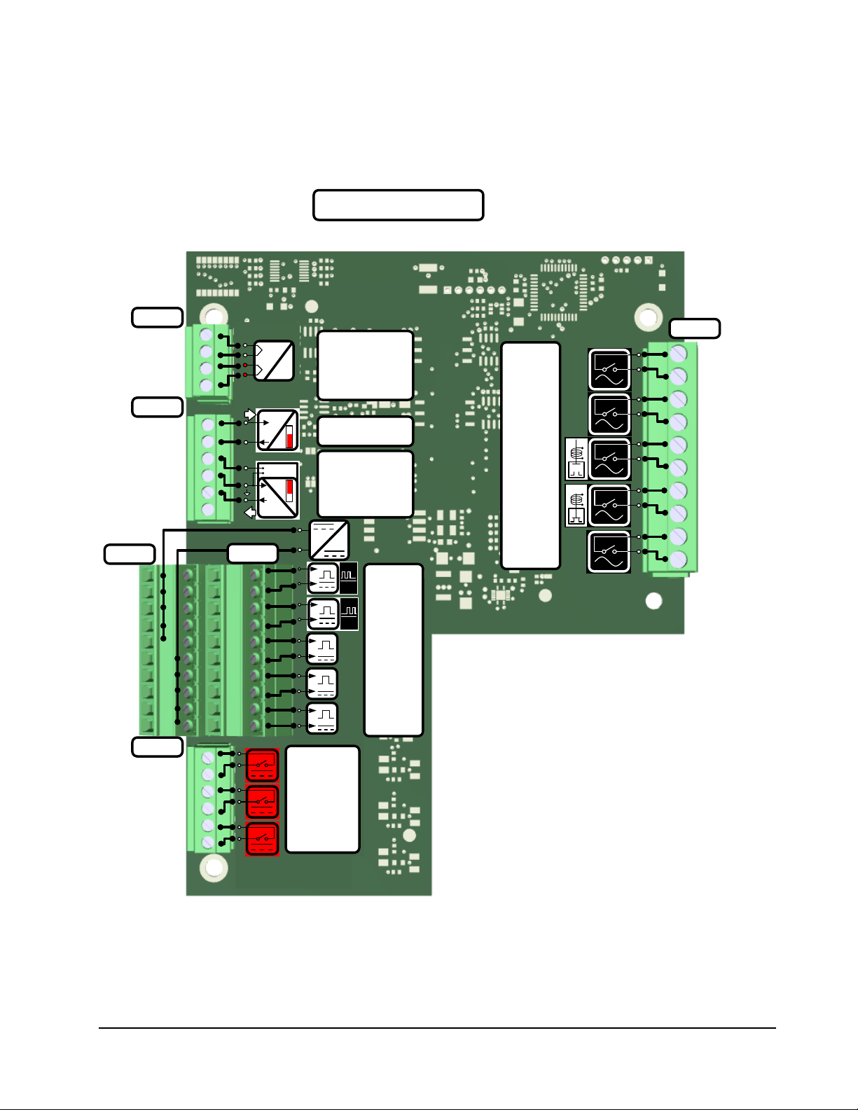
Terminal arrangements per Board 5.3
Digital Analog I/O Board (IO_DA)
5.3.1
Figure 5.1 Digital/ Analog I/O Board Terminal Block Assignments
33
Page 43
L
N
L
N
+
-
+
-
A
0°
+
-
B
90°
+
-
B
90°
+
-
5V
12V
100Ω
°C
Pt
°F
100Ω
°C
Pt
°F
1
6
TB4
5
1
TB5
TB6
TB7
TB8
TB9
TB3
TB2
TB1
+
-
+
-
A
0°
+
-
+
-
1
6
1
4
1
4
1
4
1
4
5
1
4
1
METER 0, RTD
METER 1, RTD
12 Vdc
METER 0, PORT 4
METER 0, PORT 5/6
METER 0, PORT 7
METER 1, PORT 4
METER 1, PORT 5/6
METER 1, PORT 7
METER 0, PORT 10
METER 1, PORT 10
METER 0, PORT 8
METER 1, PORT 8
METER 1, PORT 0
METER 1, PORT 1
METER 1, PORT 2
METER 1, PORT 3
LINE
METER 0, PORT 0
METER 0, PORT 1
METER 0, PORT 2
METER 0, PORT 3
LINE
IO_2M
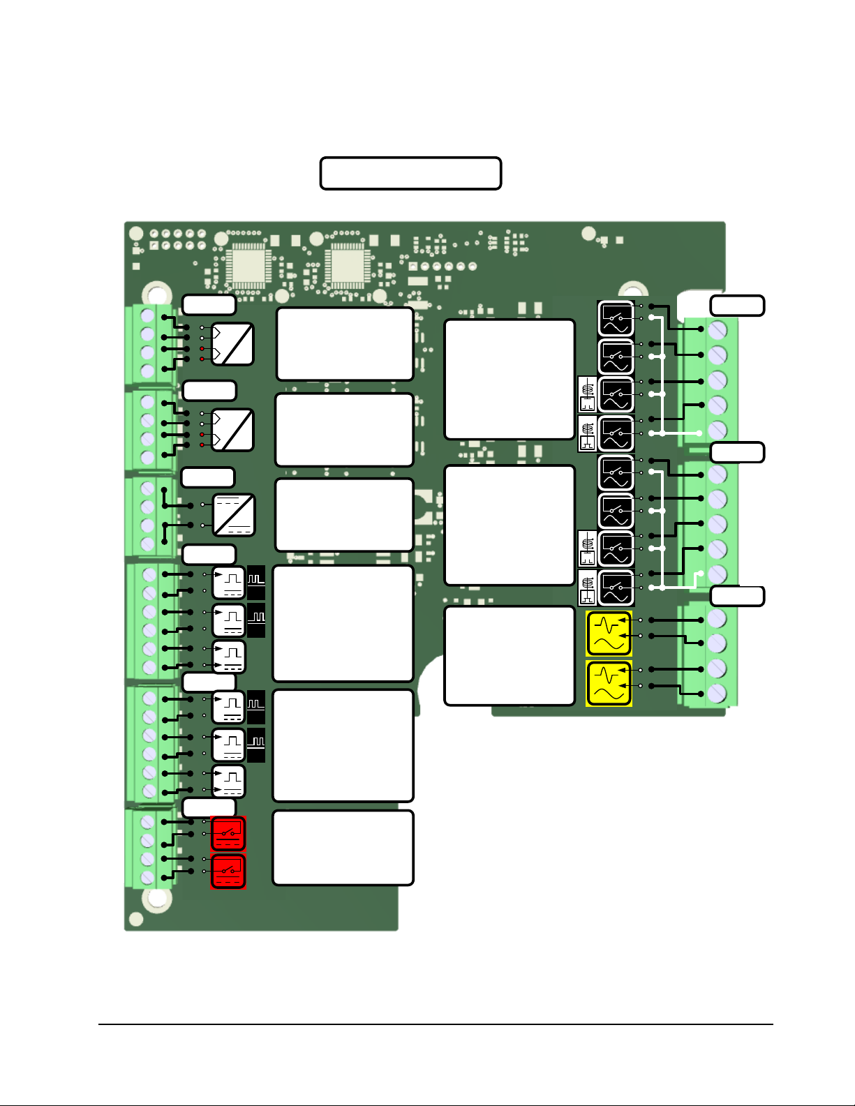
2 Meter I/O Board (IO-2M)
5.3.2
Figure 5.2 2 Meter I/O Board Terminal Block Assignments
34
Page 44

How to Connect and Wire Field Devices to the I/O Boards 5.4
In this section of the chapter we will provide examples of commonly used devices that can get wired to
the I/O boards. This is not an exhaustive listing, but intended to provide you an example of how certain
types of I/O need to get wired into the various boards.
MultiLoad II Wiring Examples:
o Flow Meter and Control Valve
o Additive
o RTD
o Analog In & Analog Out
o AC Output Wiring
o AC Input Wiring
o DC Input Wiring: Permissives/Status
o DC Output Wiring
o 2 Output Air Eliminator Wiring
o Remote Display Wiring
RCUII Wiring Examples:
- DC Input Wiring
- AC: DC Output wiring
Typical Example:
- Typical single meter example
35
Page 45

L
N
15A
L
N
L
N
VCC
A
B
GND
B
A
I/O DIGITAL/
ANALOG
I/O 2 METER
METER 0 METER 1
PORT 2
PORT 5
PORT 4
&
PORT 3.IN/
PORT 3.OUT
PORT 2.OUT
LINE.IN
PORT 2.IN/
LINE.IN
PORT 3
+
-
A
0°
+
-
B
90°
+
-
5V
12V
PORT 4.+
IN 10
OUT 9
IN 8
OUT 7
IN 6
OUT 5
IN 4
OUT 3
IN 2
OUT 1
PORT 2
PORT 3
IO_DA TB1
PORT 0
PORT 1
PORT 8
PORT 0 OUT 5
PORT 1 OUT 4
PORT 2 OUT 3
PORT 3 OUT 2
LINE IN 1
IO_2M TB3
PORT 0 OUT 5
PORT 1 OUT 4
PORT 2 OUT 3
PORT 3 OUT 2
LINE IN 1
IO_2M TB2
+
1
-
2
+
3
()
-
4
()
+
5
-
6
+
7
-
8
+
9
-
10
IO_DA TB2B
PORT 4
PORT 5
PORT 6
PORT 7
PORT 9
+
1
+
2
+
3
+
4
+
5
-
6
-
7
-
8
-
9
-
10
IO_DA TB2A
12Vdc
+
1
-
2
+
3
()
-
4
()
+
5
-
6
IO_2M TB7
PORT 4
PORT 5
PORT 7
+ 1
+ 2
- 3
-
4
12Vdc
IO_2M TB6
+
1
-
2
+
3
()
-
4
()
+
5
-
6
IO_2M TB8
PORT 4
PORT 5
PORT 7
+ 1
+ 2
- 3
-
4
12Vdc
IO_2M TB6
PORT 4.-
PORT 5.+
PORT 5.-
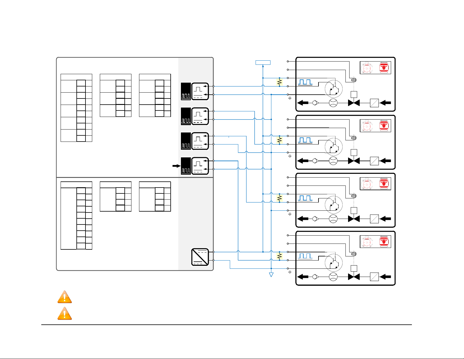
Caution: Line voltage used to drive the Digital Valve Solenoids MUST be controlled by the Ground or Overfill monitor. In the event of a Ground loss or
Overfill detection, this voltage must be switched off to ensure a failsafe shutdown of the product flow.
MultiLoad II Flow Meter and Control Valve Wiring
5.4.1
36
Page 46

L
N
15A
I/O DIGITAL/
ANALOG
I/O 2 METER
METER 0 METER 1
PORT 1
PORT 3
PORT 2/
PORT 0.OUT
PORT 0.IN/
LINE.IN
PORT 0
S
1
S
2
S
3
S
4
+
L
N
S
#1
+
L
N
S
#2
+
L
N
S
#3
+
L
N
S
#4
IO_DA ONLY!
L
N
PORT 1.OUT
PORT 1.IN/
LINE.IN
IN 10
OUT 9
IN 8
OUT 7
IN 6
OUT 5
IN 4
OUT 3
IN 2
OUT 1
PORT 2
IO_DA TB1
PORT 0
PORT 1
PORT 3
PORT 8
PORT 0 OUT 5
PORT 1 OUT 4
PORT 2 OUT 3
PORT 3 OUT 2
LINE IN 1
IO_2M TB3
PORT 0 OUT 5
PORT 1 OUT 4
PORT 2 OUT 3
PORT 3 OUT 2
LINE IN 1
IO_2M TB2
PORT 3
PORT 2.OUT/
PORT 2.IN/
LINE.IN
PORT 3.OUT
PORT 3.OUT
PORT 3.IN
Note: The output port that is selected will dictate which port is used for the additive input. For example, if Port 0 is selected as the FCM Port#, the output will
be on port 0 and the corresponding input will be at port 7. See Table above for possible port assignments.
Output
Port
Input
Port
Injector #1 0 7
Injector #2 1 6
Injector #3 2 5
Injector #4 3 4
MultiLoad II Additive Wiring: Outputs
5.4.2
37
Page 47
I/O DIGITAL/
ANALOG
I/O 2 METER
METER 0 METER 1
PORT 4.+
PORT 4.-
PORT 5.+
PORT 5.-
+
-
1
PORT 4
+
-
2
+
-
3
+
-
4
+
L
N
S
#1
+
L
N
S
#2
+
L
N
S
#3
+
L
N
S
#4
PORT 5
PORT 6/
PORT 7
+
-
5V
12V
+
1
-
2
+
3
-
4
+
5
-
6
+
7
-
8
+
9
-
10
IO_DA TB2B
PORT 4
PORT 5
PORT 6
PORT 7
PORT 9
+
1
-
2
+
3
-
4
+
5
-
6
IO_2M TB7
PORT 4
PORT 5
PORT 7
+
1
-
2
+
3
-
4
+
5
-
6
IO_2M TB8
PORT 4
PORT 5
PORT 7
PORT 7
IO_DA ONLY!
PORT 7.+
PORT 7.-
PORT 6.+/
PORT 6.-/
PORT 7.+
PORT 7.-
+ 1
+ 2
- 3
-
4
IO_2M TB6
12Vdc
+ 1
+ 2
- 3
-
4
IO_2M TB6
12Vdc
+
1
+
2
+
3
+
4
+
5
-
6
-
7
-
8
-
9
-
10
12Vdc
IO_DA TB2A
~1 kΩ,
1/4W
~1 kΩ,
1/4W
~1 kΩ,
1/4W
~1 kΩ,
1/4W
12Vdc
*Note: Most additive injection meters only provide an Open-Collector (pull down) type output. Typically a 1,000 Ohm, ¼ watt pull-up resistor needs to be
added in the pulser junction box to pull this output to 12V+ when the output is off.
Note (I/O 2 METER Only): TB7 pins 3 and 4 can be configured as Port 5 or Port 6. It is only 1 port, but because of the logic in the firmware, it may be
necessary to address it as Port 5 or Port 6 in the configuration.
*
*
*
*
MultiLoad II Additive Wiring: Inputs
5.4.3
38
Page 48

I/O DIGITAL/
ANALOG
I/O 2 METER
METER 0 METER 1
RTD
RTD.V+
RTD
100Ω
°C
Pt
°F
100Ω
°C
Pt
°F
100Ω
°C
Pt
°F
α=0.00385
100 Ω
α=0.00385
100 Ω
α=0.00385
100 Ω
RTD
RTD.R+
RTD.RRTD.COM
RTD.V+
RTD.R+
RTD.RRTD.COM
RTD.V+
RTD.R+
RTD.RRTD.COM
V+ 1
R+ 2
R- 3
COM 4
IO_DA TB4
RTD
V+ 1
R+ 2
R- 3
COM 4
IO_2M TB5
RTD
V+ 1
R+ 2
R- 3
COM 4
IO_2M TB4
RTD
Note: All 4 wires MUST be run to the sensor. Do not simply jumper REF- to COM or REF+ to V+ at the FCM II. For 3-wire and 2 wire probes, the
connection of REF- to COM and REF+ to V+ should be as close as possible to the probe (within inches).
MultiLoad II Analog Wiring
5.4.4
5.4.4.1 RTD Wiring
39
Page 49

I/O DIGITAL/
ANALOG
I/O 2 METER
METER 0 METER 1
4-20 mA-IN
+
-
+
-
+
-
5V
12V
+
-
I+
4-20 mA
I-
V+
V-
I+
I-
+
-
4-20 mA
i
4-20mA
%
i
4-20mA
%
4-20 mA-IN
I+ 1
I- 2
V+ 1
COM 2
IOUT 3
N/A 4
4-20 mA
IN
4-20 mA
OUT
IO_DA TB6
4-20 mA IN.I+
4-20 mA IN.I-
4-20 mA IN.I+
4-20 mA IN.I-
4-20 mA OUT.I
4-20 mA OUT.GND
4-20 mA OUT.V+
4-20 mA OUT.I
4-20 mA OUT.V+
4-20 mA OUT.GND
I+ 1
I- 2
V+ 1
COM 2
IOUT 3
N/A 4
4-20 mA
OUT
IO_DA TB6
4-20 mA
IN
+
1
+
2
+
3
+
4
+
5
-
6
IO_DA TB2A
12Vdc
I-
I+
4-20 mA
I-
I+
4-20 mA
i
4-20mA
%
(0 Vdc)
12-30 Vdc
i
4-20mA
%
(0 Vdc)
12-30 Vdc
*Note: The 4-20 mA receiver does not contain a voltage source. The loop must be powered either by the transmitter or by an external power supply. The
I/O Board adds 75 Ohms to the loop.
*
*
‡Note: The 4-20mA output requires a power source (12-30vdc). The 12vdc output can be used as shown here.
12 – 30 Vdc
‡
‡
5.4.4.2 MultiLoad II 4 – 20 mA Wiring
40
Page 50

L
N
15A
I/O DIGITAL/
ANALOG
I/O 2 METER
METER 0 METER 1
PORT 1
PORT 0.IN/
PORT 0.OUT
PORT 1.OUT
LINE.IN
PORT 1.IN/
LINE.IN
PORT 0
L
N
N.O.
N.C.
C
PORT 3
PORT 2
PORT 8
PORT 0 OUT 5
PORT 1 OUT 4
PORT 2 OUT 3
PORT 3 OUT 2
LINE IN 1
IO_2M TB3
PORT 0 OUT 5
PORT 1 OUT 4
PORT 2 OUT 3
PORT 3 OUT 2
LINE IN 1
IO_2M TB2
IN 10
OUT 9
IN 8
OUT 7
IN 6
OUT 5
IN 4
OUT 3
IN 2
OUT 1
PORT 8
IO_DA TB1
PORT 0
PORT 1
PORT 2
PORT 3
IO_DA ONLY!
PORT 2.IN/
LINE.IN
PORT 3.IN/
LINE.IN
PORT 8.IN
PORT 2.OUT
PORT 3.OUT
PORT 8.OUT
COM
IN X
M
L
N
L
N
L
N
L
N
Note: This shows a typical configuration. AC outputs can be assigned to any unused AC output.
MultiLoad II AC Output Wiring
5.4.5
41
Page 51

L
N
15A
I/O DIGITAL/
ANALOG
I/O 2 METER
METER 0 METER 1
PORT 8
PORT 8.N
PORT 8.N
PORT 8.L
PORT 8.L
PORT 8
PORT 8
PORT 8.L
PORT 8.N
L 1
N 2
L 3
N 4
IO_2M TB1
PORT
1.8
L 1
N 2
L 3
N 4
IO_2M TB1
PORT
0.8
L
N
L
N
L
N
Note: This shows a typical configuration. AC Permissive/Status inputs can be assigned to any unused AC input.
MultiLoad II AC Input Wiring
5.4.6
42
Page 52

I/O DIGITAL/
ANALOG
I/O 2 METER
METER 0 METER 1
PORT 5
PORT 4.-
PORT 5.-
PORT 4.+
PORT 5.+
PORT 4
PORT 7
PORT 6
PORT 9
IO_DA ONLY!
PORT 6.+
PORT 7.+
PORT 9.+
PORT 6.-
PORT 7.-
PORT 9.-
+
1
-
2
+
3
-
4
+
5
-
6
+
7
-
8
+
9
-
10
IO_DA TB2B
PORT 4
PORT 5
PORT 6
PORT 7
PORT 9
+
1
-
2
+
3
-
4
+
5
-
6
PORT 5
PORT 7
IO_2M TB7
PORT 4
+
1
-
2
+
3
-
4
+
5
-
6
PORT 5
PORT 7
IO_2M TB8
PORT 4
IO_DA ONLY!
+
-
&
+
-
+
-
+
-
+
-
+
-
5 – 30 Vdc
M
L
N
L
N
Note: This shows a typical configuration. DC Permissive/Status inputs can be assigned to any unused DC input.
MultiLoad II DC Permissive/Status Wiring
5.4.7
43
Page 53

I/O DIGITAL/
ANALOG
I/O 2 METER
METER 0 METER 1
PORT 11
PORT 10.OUT/
PORT 11.OUT
PORT 10.IN/
PORT 11.IN
PORT 0.10
+
-
N.O.
N.C.
C
PORT 12
IO_DA ONLY!
PORT 12.IN
PORT 12.OUT
IO_DA ONLY!
M
+
-
N
+
-
5 – 30 Vdc
PORT 10.OUT/
PORT 10.IN/
PORT 1.10
+
-
+
-
+
-
+
-
IN 1
OUT 2
IN 3
OUT 4
IN 5
OUT 6
IO_DA TB3
PORT 10
PORT 11
PORT 12
COM
IN X
IN 1
OUT 2
IN 3
OUT 4
IO_2M TB9
PORT
0.10
IN 1
OUT 2
IN 3
OUT 4
IO_2M TB9
PORT
1.10
PORT 0.10.IN
PORT 1.10.OUT
PORT 1.10.IN
PORT 0.10.OUT
PORT 10/
PORT 10/
+
-
L
N
Note: This shows a typical configuration. DC outputs can be assigned to any unused DC output.
*Note: For I/O Board firmware v036 or greater, any DC output port can be configured as an output pulse.
*
MultiLoad II DC Output Wiring
5.4.8
44
Page 54
L
N
15A
I/O DIGITAL/
ANALOG
I/O 2 METER
METER 0 METER 1
PORT 2
&
PORT 3.IN/
PORT 3.OUT
PORT 2.OUT
LINE.IN
PORT 2.IN/
LINE.IN
PORT 3
IN 10
OUT 9
IN 8
OUT 7
IN 6
OUT 5
IN 4
OUT 3
IN 2
OUT 1
PORT 2
PORT 3
IO_DA TB1
PORT 0
PORT 1
PORT 8
PORT 0 OUT 5
PORT 1 OUT 4
PORT 2 OUT 3
PORT 3 OUT 2
LINE IN 1
IO_2M TB3
PORT 0 OUT 5
PORT 1 OUT 4
PORT 2 OUT 3
PORT 3 OUT 2
LINE IN 1
IO_2M TB2
L
N
L
N
N
L
1
2
3
Note: With only two states returned from the air eliminator, flow must be
completely stopped to purge air. To purge air by only slowing the rate, a 3
output air eliminator head must be used.
Note: When the level drops below Low, the power will be removed from the
digital valves, stopping flow before the air eliminator is completely drained.
MultiLoad II 2 Output Air Eliminator Wiring
5.4.9
45
Page 55

I/O DIGITAL/
ANALOG
I/O 2 METER
METER 0 METER 1
PORT 11/
PORT 0.10
+
-
5 – 28 Vdc
PORT 1.10
+
-
+
-
PORT 1.10.OUT
PORT 1.10.IN
PORT 11.OUT/
PORT 11.IN/
IN 1
OUT 2
IN 3
OUT 4
IN 5
OUT 6
IO_DA TB3
PORT 10
PORT 11
PORT 12
PORT 10/
PORT 0.10.OUT
PORT 0.10.IN
PORT 10.OUT/
PORT 10.IN/
IN 1
OUT 2
IN 3
OUT 4
IO_2M TB9
PORT
0.10
IN 1
OUT 2
IN 3
OUT 4
IO_2M TB9
PORT
1.10
≥ 500 mA
RESET
12 V COM
COUNT +
12 Vdc
Note: Use only model E1613. The Lectro Count +12Vdc, 12V common can be supplied by an external source.
Note (I/O DIGITAL/ ANALOG Only): Connect Port 10 to Lectro Count output pulse. Connect Port 11 to Lectro Count reset pulse.
Note (I/O 2 METER Only): Connect Port 0.10 to Lectro Count output pulse. Connect Port 1.10 to Lectro Count reset pulse.
5.4.10
MultiLoad II Lectro Count Remote Display Wiring
46
Page 56

VCC
A
B
GND
B
A
I/O DIGITAL/
ANALOG
I/O 2 METER
METER 0 METER 1
PORT 5
PORT 4
+
-
5V
12V
PORT 4.+
+
1
+
2
+
3
+
4
+
5
-
6
-
7
-
8
-
9
-
10
IO_DA TB2A
12Vdc
+ 1
+ 2
- 3
-
4
12Vdc
IO_2M TB6
+ 1
+ 2
- 3
-
4
12Vdc
IO_2M TB6
PORT 4.-
+
-
A
0°
+
1
-
2
+
3
-
4
+
5
-
6
IO_2M TB7
PORT 4
PORT 5
PORT 7
+
1
-
2
+
3
-
4
+
5
-
6
IO_2M TB8
PORT 4
PORT 5
PORT 7
+
1
-
2
+
3
-
4
+
5
-
6
+
7
-
8
+
9
-
10
IO_DA TB2B
PORT 4
PORT 5
PORT 6
PORT 7
PORT 9
12 Vdc
5.4.11
RCU II DC Input Wiring
47
Page 57

L
N
15A
I/O DIGITAL/
ANALOG
I/O 2 METER
METER 0 METER 1
PORT 1
PORT 0.IN/
PORT 0.OUT
PORT 1.OUT
LINE.IN
PORT 1.IN/
LINE.IN
PORT 0
PORT 0 OUT 5
PORT 1 OUT 4
PORT 2 OUT 3
PORT 3 OUT 2
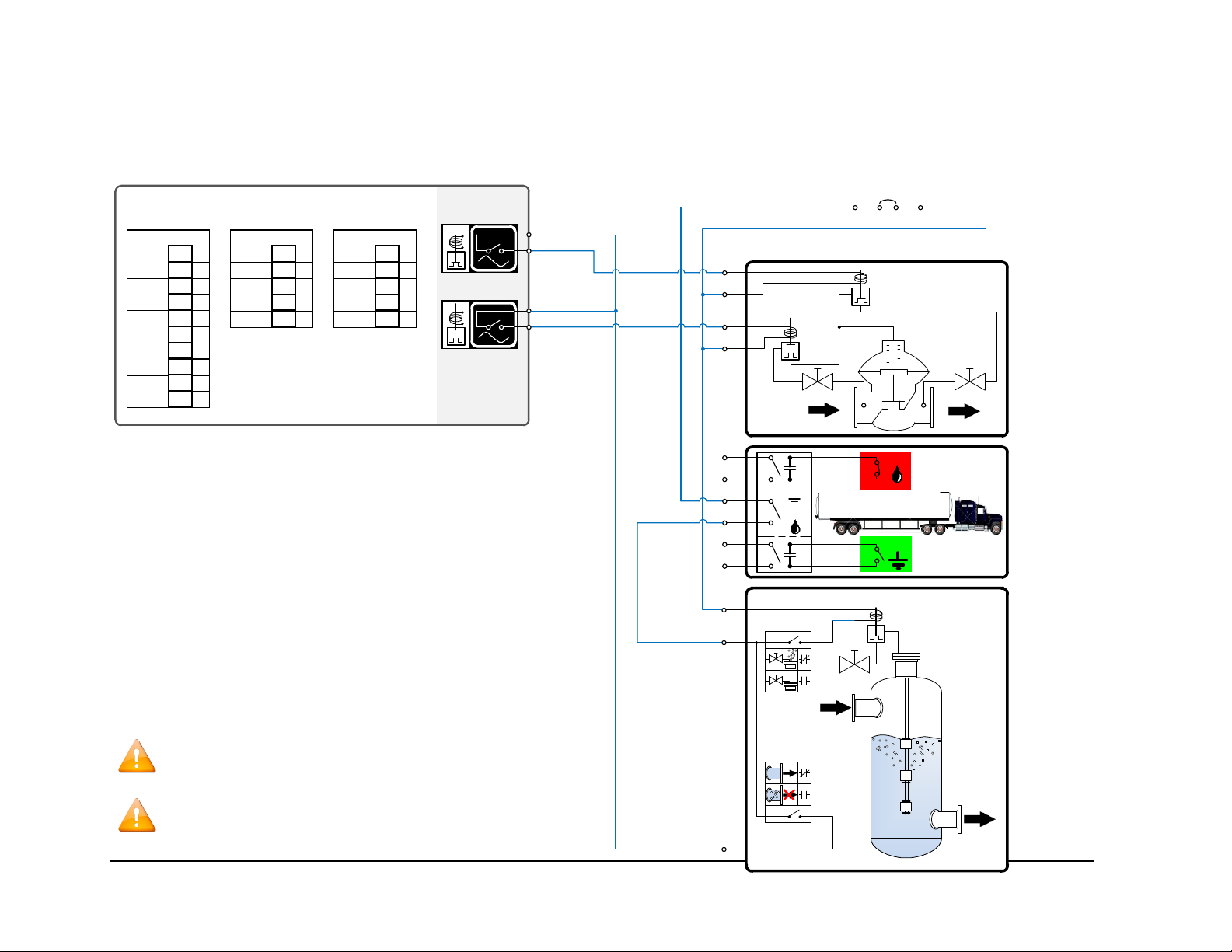
LINE IN 1
IO_2M TB3
PORT 0 OUT 5
PORT 1 OUT 4
PORT 2 OUT 3
PORT 3 OUT 2
LINE IN 1
IO_2M TB2
IN 10
OUT 9
IN 8
OUT 7
IN 6
OUT 5
IN 4
OUT 3
IN 2
OUT 1
PORT 8
IO_DA TB1
PORT 0
PORT 1
PORT 2
PORT 3
L
N
N.O.
N.C.
C
N
L
L
N
L
N
Note: This shows a typical configuration. AC outputs can be assigned to any unused AC output.
5.4.12
RCU II AC Output Wiring
48
Page 58

I/O DIGITAL/
ANALOG
I/O 2 METER
METER 0 METER 1
PORT 10.OUT/
PORT 10.IN/
PORT 0.10
PORT 10.OUT/
PORT 10.IN/
PORT 1.10
+
-
+
-
IN 1
OUT 2
IN 3
OUT 4
IN 5
OUT 6
IO_DA TB3
PORT 10
PORT 11
PORT 12
IN 1
OUT 2
IN 3
OUT 4
IO_2M TB9
PORT
0.10
IN 1
OUT 2
IN 3
OUT 4
IO_2M TB9
PORT
1.10
PORT 0.10.IN
PORT 1.10.OUT
PORT 1.10.IN
PORT 0.10.OUT
PORT 10/
PORT 10/
+
-
N.O.
N.C.
C
N
L
+
-
5 – 30 Vdc
+
-
L
N
Note: This shows a typical configuration. DC outputs can be assigned to any unused DC output.
5.4.13
RCU II DC Output Wiring
49
Page 59

5.4.14
Typical 1 Meter Application Wiring Example: IP&E Drawing (Electrical Wiring Schedule)
50
Page 60

Chapter
6
Chapter 6 Configurations
Switch Access Control 6.1
The MultiLoad II contains switches which limit menu and configuration access. These switches limit
users from accessing Program Mode, as well as from changing Weights and Measures controlled
parameters.
In Program Mode, the operator has access to the following:
- The Configuration Menu parameters.
- The Diagnostics Menu and its functions.
- Other administrative procedures, such as clearing high-level alarms.
To access Program Mode, the MultiLoad II/ RCU II terminal operator must:
1. Move the Program Mode switch into the active position.
2. At the idle card-in screen, enter the security code (default security code is 000000) and press
the <Next> key.
External Switch Access Control (MultiLoad II Only)
6.1.1
One access control switch option is a pair of external access control switches. These switches limit
access to Program Mode and changes to Weights and Measures controlled parameters.
EXTERNAL SWITCHES SERVE NO FUNCTION ON THE RCU II SINCE PASSWORD ACCESS ALWAYS
OVERRIDES THE PROGRAM SWITCH SETTING. WEIGHTS AND MEASURES FUNCTIONALITY IS
UNDEFINED FOR THE RCU II.
YOUR LOCAL WEIGHTS AND MEASURES OFFICE MAY NEED TO BE CONTACTED AFTER BREAKING THE
SEAL AND CHANGING PARAMETERS. THIS IS TYPICALLY DONE ONLY DURING METER PROVING OR
TEMPERATURE CALIBRATION.
51
Page 61

Depending on the date of manufacture, the MultiLoad II may have one of three types of external switch
design. All can be sealed and locked to prevent access to Program Mode and to prevent changes of
Weights and Measures controlled parameters.
External Type 1 Program / W&M Switches
6.1.2
This design consists of two separate external rotary switches: one for Program Mode Access, and one
for W&M Change Access. Each switch has an external fold-down cover that can be locked or sealed
with a wire and lead seal to prevent moving the switch into the active state. Each cover will also be
stamped as “W&M” or “Program” to indicate their respective function.
Figure 6.1 Type 1 Program / W&M Switches
External Type 2 Program / W&M Switches
6.1.3
This design consists of a single 3-position external rotary switch with two individual covers which may
be locked and sealed with a wire and lead seal. The covers limit the switch rotation to three positions:
A - Two covers closed: Program access denied and Weights and Measures access denied.
Figure 6.2 Type 2 Program / W&M Switches
52
Page 62

B - First cover open: Program access allowed and Weights and Measures access denied.
C - Both covers open: Program access allowed and Weights and Measures access allowed.
53
Page 63

External Type 3 Program / W&M Switches
6.1.4
The third design consists of two separate external magnetic bolts, one for program mode access, and
one for W&M change access. Program or W&M access is achieved by removing the corresponding
bolt. Each bolt has a small hole that can be sealed with a wire and lead seal to detect unauthorized
access. A single fold--down cover can be locked to prevent bolt removal. The cover is marked “W&M”
or “Program” adjacent to each bolt to indicate the bolt function.
Figure 6.3 Type 3 Program / W&M Switch with Magnetic Bolts
Do not use a wrench to tighten the bolts. Insert the bolts and hand tighten only. Over-
tightening will damage the bolt assembly.
Internal Switch Access Control
6.1.5
Two DIP switches on the CPU board also provide the closure of the program mode / W&M switch
contacts. When the MultiLoad II/ RCU II does not have the external Program Mode / W&M switch
installed, it is necessary to use these DIP switches on the CPU board to enable program mode and
W&M access.
The switches are numbered 1 through 4, with 1 being closest to the front of the enclosure (top of the
picture), and 4 being towards the back of the enclosure (bottom of the picture).
When the switch is in the ON position, the switch is in the active state, allowing access. A switch is ON
when it moves right, and OFF when moved to the left.
Switch #3 is the program mode switch. Switch #4 is the W&M access switch. In the example in Figure
6.4 below, the program mode switch is currently active, while the W&M switch is not active. Figure 6.5
shows the location of the DIP switch on revision 2.0 CPU boards.
A switch input is active when either the DIP switch OR the external switch is active (ON).
54
Page 64

55
Page 65

Figure 6.4 CPU DIP Switches for Program and W&M Access (rev 1.0)
Figure 6.5 CPU DIP Switches for Program and W&M Access (rev 2.0) Field Switch Access Control
(MultiLoad II Only)
The MultiLoad II also has the ability to accept field inputs for the program mode and W&M access
switches. Review the “MultiLoad II User Guide” for more information.
RCU II INPUTS RECEIVED FROM EXTERNAL FIELD DEVICES CANNOT BE CONFIGURED TO CONTROL
PROGRAM MODE ACCESS. WEIGHTS AND MEASURES FUNCTIONALITY IS UNDEFINED FOR RCU II
MultiLoad II/ RCU II DIV-2 Keypad 6.2
The MultiLoad II/ RCU II DIV-2 keypad has 47 keys, including alpha, numeric, and function keys, which
are used to:
- Select menu items and fields
- Enter data in fields
- Initiate actions
- Return to previous screens
56
Page 66

M A I N M E N U
Configuration
Diagnostics
Views and Inquiries
SD Card
Factory Defaults
Next Prev Exit Enter
D I A G N O S T I C S M E N U
Card Reader Preset
COM Loopback Meters
Serial Ports Components
PTB Serial –Test Additives
Network Test Sampler
Keypad Custom Logic
Display Modbus Device
Unicode Thread Info
FCM Com SD Card
PCM Com
FCM Health
PCM Health
RCU
Bay
Next Prev Exit Enter
Numeric keys (1 through 9 and 0) are used to enter numeric data. Alpha keys are used to enter text,
and also to select/deselect alpha character entry. The CLR key is used to clear data entered in error;
this is a backspace key erasing characters as the cursor moves backwards.
Menus and Screens 6.3
The MultiLoad II Main Menu is shown below. From this menu, you select submenus:
The reverse video highlight bar indicates the current selection. Press Next to select Diagnostics, and
then press the Enter key to go to the Diagnostics Menu.
For menu options and function screen items, pressing the Next key moves the selection bar down, and
pressing the Prev (Previous) key moves the selection bar up.
57
Page 67

RCU GENERAL SETUP
RCU Address: 001
Card Reader: DISABLD
Processing Mode : Remote
Swing Arn Secondary: DISABLD
Terminal Name: Toptech Terminal
Security Accounts
Next Prev Exit Enter
RCU GENERAL SETUP
RCU Address: █
Card Reader: DISABLD
Processing Mode: Remote
Swing Arm Secondary: DISABLD
Terminal Name: Toptech Terminal
Security Accounts
Enter Exit
To return to the Main Menu, press EXIT. To return to any previous screen, press the EXIT key.
Field Modification and Data Entry
6.4
MultiLoad II/ RCU II will have all fields populated with default values. There are two types of fields,
toggle or data entry. Toggle fields contain a number of choices. Scroll through the choices by pressing
the Enter key. Data entry fields require that a value be entered into the field within a given, applicable
range. In the example below, RCU Address field is highlighted:
Press ENTER to choose the field. A blinking cursor indicates that data can be entered.
Type in the new value (e.g. 123) and press ENTER. The new value displays on the screen.
58
Page 68

RCU GENERAL SETUP
RCU Address: 123█
Card Reader: DISABLD
Processing Mode: Remote
Swing Arn Secondary: DISABLD
Terminal Name: Toptech Terminal
Security Accounts
Next Prev Exit Enter
RCU GENERAL SETUP
RCU Address: 123
Card Reader: DISABLD
Processing Mode: Remote
Swing Arm Secondary: DISABLD
Terminal Name: Toptech Terminal
Security Accounts
Enter Exit
Using this same screen as an example, the Processing Mode line is selected and ENTER is pressed;
use the NEXT or PREV keys to toggle between the values ENABLED and DISABLED, as shown below.
You must then press ENTER to accept the desired choice.
MultiLoad II/ RCU II Preliminary Configuration 6.5
1) Power-on the MultiLoad II/ RCU II.
2) When the MultiLoad II is first powered-on, the card–in screen appears, indicating Operating Mode.
An RCU II may initially display “System Unavailable” because it is unconnected to a host system.
59
Page 69

For Access
Insert Driver Card
M A I N M E N U
Configuration
Diagnostics
Views and Inquiries
SD Card
Factory defaults
Next Prev Exit Enter
3) Go to program mode by entering 00000 on the keypad, then press Next.
A MultiLoad II must have the Program switch set to allow access to Program Mode (See section
6.1).
00000 is the factory default access code. See the “MultiLoad II User Guide,” RCU General
Setup section for changing or adding new access codes.
Note that unlike MultiLoad II, Program switches or CPU DIP switches never deny access to
RCU II Program Mode.
4) The program mode main menu displays (MultiLoad II/RCU II):
5) Press Enter to access the Configuration menu:
60
Page 70

C O N F I G U R A T I O N M E N U
Communication
Network
RCU General Setup
RCU Setup
Security Setup
Equipment Setup
FCm Type Setup
Alarm Setup
Products
Additive Cal.
Remote Adtv Cal.
Access ID's
Custom Logic
Customer Logo Setup
Next Prev Exit Enter
C O N F I G U R A T I O N M E N U
Communication
Network
RCU Setup
Customer Logo Setup
Date & Time
Next Prev Exit Enter
RCU GENERAL SETUP
RCU Address: 001
Card Reader: DISABLD
Processing Mode: Remote
Swing Arm Secondary: DISABLD
Terminal Name: Toptech Terminal
Security Accounts
Next Prev Exit Enter
RCU GENERAL SETUP
RCU Address: 001
Card Reader: Slot CAPTIVE
Password: *****
Security: DISABLED
RCUOP Protocol
Next Prev Exit Enter
C O N F I G U R A T I O N M E N U
Date & Time
Printing
Trace
Reports
6) Press Enter to access RCU General Setup/ RCU Setup:
5) Press Enter to access the Configuration menu.
6) Press Enter to access RCU General Setup.
MultiLoad II RCU II
7) Press Enter and key in RCU address (001) of MultiLoad II/ RCU II:
MultiLoad II RCU II
61
Page 71

D I A G N O S T I C S M E N U
Card Reader
COM Loopback
Serial Ports
Network Test
Keypad
Display
Unicode
RCU
Next Prev Exit Enter
000 FCM COM DIAGNOSTICS
00-Ok
Exit
RCU I/O DIAGNOSTICS
I/O Board Com: Ok F/W Rev: 033
Timeouts: 000000003 Com Lost: 000000001
[1]AC Output 0 - OFF DC Input 4 – OFF
[2]AC Output 1 - OFF DC Input 5 – OFF
[3]AC Output 2 - OFF DC Input 6 – OFF
[4]AC Output 3 - OFF DC Input 7 – OFF
[5]AC Output 8 - OFF DC Input 9 – OFF
[6]DC Output 10 – OFF Counter 4 - 00000
[6]DC Output 11 – OFF Counter 5 - 00000
[6]DC Output 12 – OFF Program Key– OFF
W&M Key – OFF
Battery @ 36C 3.24V
Battery 100%
Exit Clear
D I A G N O S T I C S M E N U
Card Reader Preset
COM Loopback Meters
Serial Ports Components
PTB Serial –Test Additives
Network Test Sampler
Keypad Custom Logic
Display Modbus Device
Unicode Thread Info
FCM Com SD Card
PCM Com
FCM Health
PCM Health
RCU
Bay
Next Prev Exit Enter
8) Press Exit to return to the Configuration Menu.
9) Select and press Enter to return to the Main Menu.
10) If the MultiLoad II/ RCU II has a Program/Weights and Measures switch, return the switch to
Operating Mode.
Verifying Communications between MultiLoad II/ RCU II and I/O Board 6.6
1) Enter program mode by pressing 00000 on the keypad, then press Next key.
2) Select diagnostics from main menu:
MultiLoad II RCU II
3) For MultiLoad II, select FCM COM. For RCU II, select RCU:
4) If screen displays “00-OK” (or “I/O Board Com: OK” for the RCU II), the I/O board is communicating
5) If the I/O board is not communicating the message “00-ERR” appears (or “I/O Board Com: ERR” for
with the MultiLoad II or RCU II.
the RCU II).
MultiLoad II RCU II
62
Page 72

6) If 00-ERR (or “I/O Board Com: ERR”) appears, verify the communication parameters for Com0
within the Communication Setup Menu. This menu is located under the Configuration Menu. The
Com0 communication settings required for the I/O board are .57.6 (K Baud), None (Parity), 8 Data
(bits), 1 Stop (bit), Single, and I/O Board (type of serial device). This is correctly set in the factory
when an RCU II is assembled, but it is possible for the settings to be updated by the installer.
Using I/O Diagnostics 6.7
MultiLoad II: Consult the MultiLoad II User Manual for diagnostics functions.
RCU II: Each output is listed on the screen, adjacent to a number. Press a number on the keypad that
corresponds to the output under test. If the connection has been made properly, the field device will
actuate.
NOTE: If numbers do not appear next to the outputs, enter Configurations RCU Setup and
change the password from the default “00000”.
Inputs: Each input is listed on the screen adjacent to its status. Each input will be in either the ON or
OFF state. Activate each input from the field. If the circuit is connected properly, the state change can
be observed.
For the counter inputs, the totals will accrue as long as they are receiving pulses (MultiLoad II/ RCU
II):
63
Page 73

64
Page 74

Chapter
7
DISPLAY
KEYPAD
CARD READER
SLOT
Chapter 7 Service and Repair
Do not service MultiLoad II/ RCU II without disconnecting the supply circuit. Keep
the enclosure tightly closed while circuits are live.
Using a magnetic screwdriver is very helpful in retaining the screws during removal and
installation.
Overview and Subassemblies 7.1
Figure 7.1 MultiLoad II (ML II) / Remote Control Unit II (RCU II) Division 2 Unit
65
Page 75
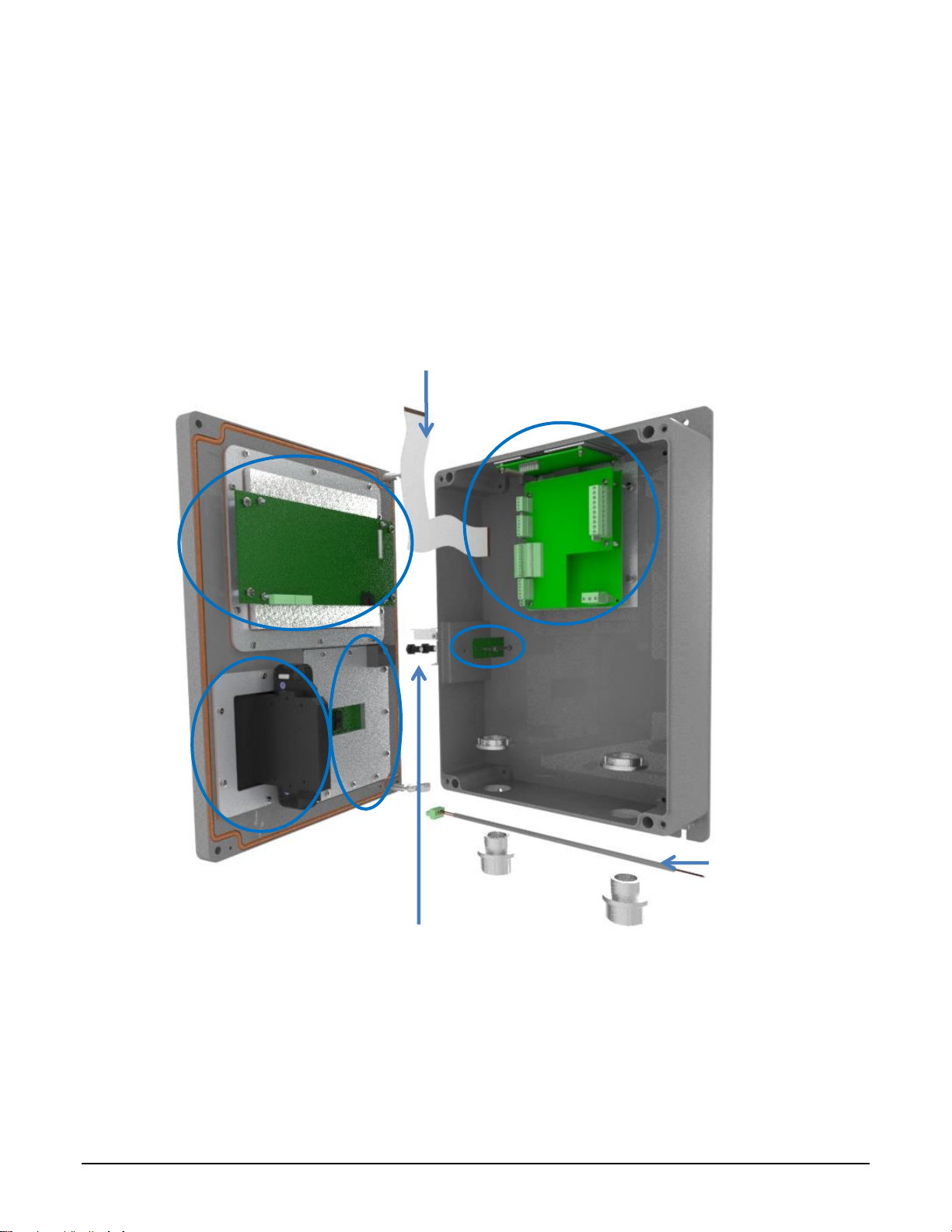
4
1
BACKLIGHT POWER
CABLE
W&M MAGNETIC
BOLTS
DISPLAY INTERFACE
CABLE
2 2
5
3
The MultiLoad II/ RCU II DIV-2 has been constructed with replaceable modules or sub-assemblies that
are available from Toptech. These include:
- CPU Subassembly (CPU Chassis, CPU Board, Power Supply/ COM Board, I/O Board) 1
- Display Subassembly (Active Matrix Display and Display Board) 2
- Keypad 3
- Prox Reader 4
- W&MS Subassembly 5
- Iceshield
The following sections describe how to remove and replace each subassembly and, when applicable,
how to further disassemble the subassembly.
Figure 7.2 ML II/ RCU II Div2 Unit Assembly Slotted Card Holder with MT11
66
Page 76

POWER
SUPPLY/COMMUNICATIONS
BOARD
CPU Subassembly Removal and Replacement 7.2
The CPU subassembly exists out of the CPU chassis with the power supply/communications board and
the CPU mounted. Optionally, an I/O board can be added to this subassembly. The CPU subassembly
is comprised of different Toptech Parts.
Figure 7.3 CPU Board, Power Supply / Comm Board, I/O Board with Chassis
Part numbers:
Power Supply & Communication board
AC –Power Supply Board: 4728
DC – Power Supply Board: 4729
CPU Board: 4727
I/O Boards:
Digital/Analog I/O Board: 4718
2 Meter I/O Board: 4723
67
Page 77

Removal:
1. Disconnect all field wiring from the I/O board.
2. Disconnect all Serial Communications from the Power Supply/COM board.
3. Disconnect Main Power from the Power Supply/COM board.
4. Disconnect the flat display cable (after releasing the cam lock) and display power cable.
5. Disconnect the W&M Access/Program Mode switch cable from the CPU board.
6. Remove the four chassis mounting screws (not the mounting screws for the I/O board or Power
Supply / COM board).
7. Carefully remove the CPU chassis from inside the base by removing the CPU board side of the
chassis first.
Installation:
1. Carefully insert the CPU chassis back into the enclosure.
2. Install the chassis mounding screws.
3. Connect the W&M Access/Program Mode switch cable to the CPU board.
4. Reconnect the display power cable and the flat display cable (remember to secure the cam
lock).
5. Connect the Main Power to the Power Supply/COM board.
6. Connect all Serial Communications to the Power Supply/COM board.
7. Connect all field wiring to the I/O board.
68
Page 78

DISPLAY
ASSEMBLY
Display Subassembly Removal and Replacement 7.3
Part Number: DIV-2- Display Subassembly: 4720
Backlight power cable: 2224
Removal:
1. Disconnect the flat display cable (after releasing the cam lock –see 7.3.1), display power cable
and the keypad cable.
2. While supporting the display subassembly, remove the four mounting screws.
3. Do not attempt to disassemble the display subassembly. Return entire subassembly to
Toptech for repair after receiving an RMA number.
Installation:
1. While supporting the display subassembly, install the four mounting screws.
2. Connect the keypad cable, display power cable and the flat display cable.
3. Verify routing and clearance of the cable
7.3.1
Part Number: Display Interface Cable: 1250
Figure 7.4 ML II/ RCU II Div2 Unit Cover Display Assembly
Flat Display Cable Connector: Remove and Connect
69
Page 79

Removal:
1. To remove the display cable, rotate the cam to the open (up) position (see Figure 7.5).
2. Gently pull the cable straight out free of the connector.
Installation:
1. To install the display cable, make sure the cam is in the open (up) position.
2. Gently insert the cable with the dark insulated side towards the cam (see Figure 7.6). When
inserting the cable, ensure that it is not tilted to one side and that the bottom of the cable is
completely seated in the connector.
3. Rotate the cam to the closed (down) position to lock in place (see Figure 7.7).
Figure 7-5 Cam lock in the Open (Up) position Figure 7-6 Cam lock in the closed (down)
position
Figure 7-7 Display Cable Insertion
Keypad Removal and Replacement 7.4
Part Number: DIV-2-Keypad: 1257
70
Page 80

KEYPAD
ASSEMBLY
Removal:
1. Disconnect the keypad cable from the back of the keypad.
2. Using a #2 screwdriver, remove all screws holding on the keypad plate.
3. Remove the plate.
4. Using a flat screwdriver, carefully pry out the keypad.
Installation:
1. Carefully install the keypad into the cover.
2. Install the keypad plate and retaining screws.
3. Reconnect the keypad cable to the keypad.
7.5.1
Figure 7.8 ML II/ RCU II Div2 Unit Cover Keypad Assembly
Card Reader Removal and Replacement 7.5
Slotted Card Holder Mounted Prox Reader Removal and Replacement: (Current Model)
71
Page 81

PROX READER
Part Number: 4726
Removal:
1. Disconnect the prox reader cable from the display subassembly.
2. Remove the 4 screws from the card holder back.
3. Remove the screw at the top of the card reader.
4. Lift the card reader off the card reader backplate. It is not necessary to remove the card reader
back plate.
Installation:
1. Replace the card reader.
2. Reattach the card reader to the back plate. Hook the bottom of the card reader onto the bottom
of the back plate. Align the top hole of the reader with the threaded insert on the back plate.
Reinstall the flat head screw and tighten.
3. Align the assembly back with the card holder. Insert the 4 screws. Start by hand and tighten.
4. Connect the prox reader cable to the display subassembly.
7.5.2
Removal:
1. Disconnect the prox reader cable from the display subassembly.
2. Remove the two nuts holding prox reader.
Figure 7.9 Exploded View Front Cover Assembly: Slotted Card Holder with MT11
Bracket Mounted (Obsolete) Prox Reader Removal and Replacement:
72
Page 82

3. Remove the prox reader.
Installation with Older Part:
1. Reinstall the prox reader with the two nuts.
2. Connect the prox reader cable to the display subassembly.
Figure 7.10 ML II/ RCU II Div2 Cover Assembly Prox Bracket Mount Thinline II (Obsolete)
Slotted Card Holder Mounted Prox Reader HID (Obsolete) Removal and Replacement:
7.5.3
Replacement part number: 4726
Removal:
1. Disconnect the prox reader cable from the display subassembly.
2. Remove the 2 screws attaching the card reader.
3. Remove the prox reader.
1. Installation with Older Part: Replace the card reader. Orient the LED toward the top.
73
Page 83
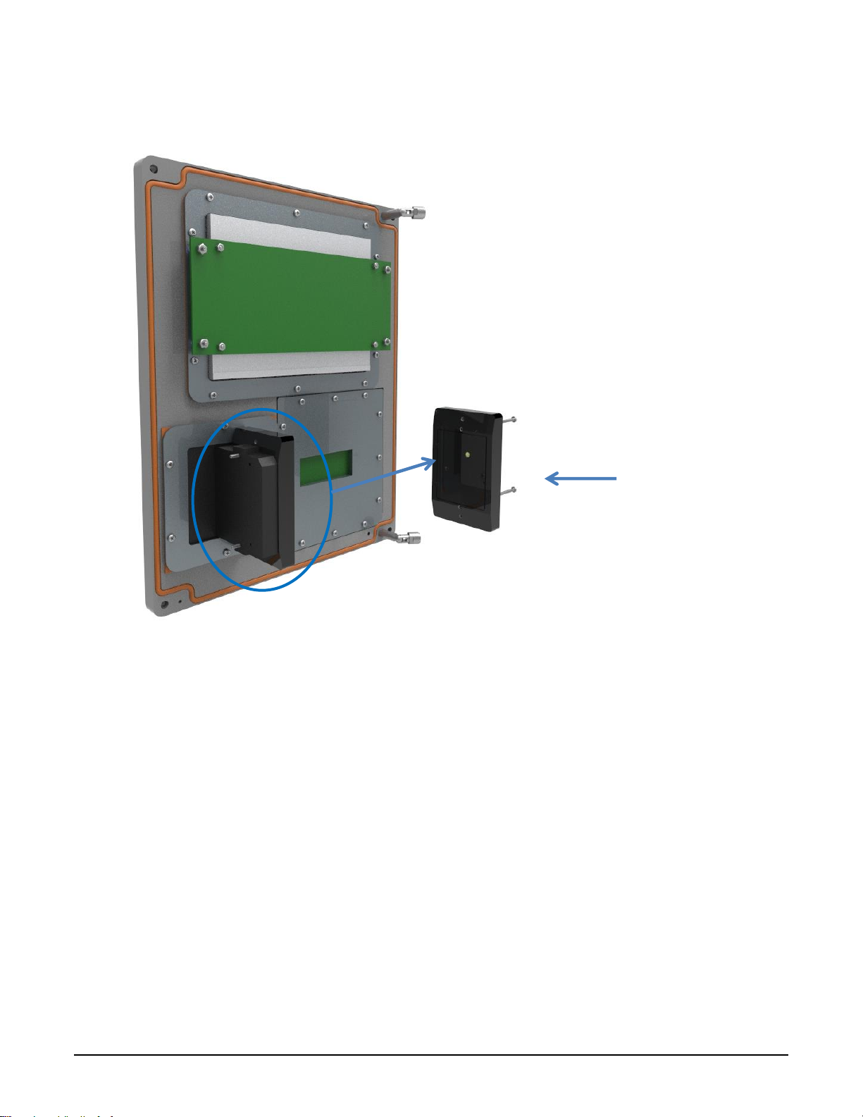
PROX
READER
2. Reinstall the screws and lockwasher.
3. Connect the prox reader cable to the display subassembly.
Figure 7.11 ML II/ RCU II Div2 Cover with Slotted Card Holder Thinline II (Obsolete)
Slotted Card Holder Mounted TWIC Reader (Obsolete) Removal and Replacement:
7.5.4
Replacement part number: 4726
Removal:
1. Disconnect the prox reader cable from the display subassembly.
2. Remove the 2 screws attaching the card reader.
3. Remove the prox reader.
Installation with Older Part:
1. Replace the card reader. Orient the LED toward the top.
2. Reinstall the screws and lockwasher.
74
Page 84

3. Connect the prox reader cable to the display subassembly.
Figure 7.12 ML II/ RCU II Div2 Unit Assembly Prox/TWIC Slotted Card Holder RP15 (Obsolete)
W&M Switch Assembly Removal and Replacement 7.6
Part Number: W&M Assembly Board: 1900
W&M Bolt: 1901
This assembly is only found for MultiLoad II DIV2 devices.
Removal:
1. Unplug the cable from the CPU board. Carefully depress the locking mechanism on the
connector and gently pull.
2. Remove the two screws securing the switch board assembly.
3. Remove the board.
75
Page 85

Installation:
1. Install the new switch assembly using the same screws. Install with the cut corners facing
outward. DO NOT over-tighten and simply secure gently. Over-tightening will crack the ferrite
rings, damaging the switch.
2. Reinstall the connector.
3. Installation complete.
Figure 7.13 ML II/ RCU II DIV2 W&M Assembly
Ice Shield Removal and Replacement 7.7
Part Number: Ice Shield: 2443
The ice shield is a current standard on MultILoad II and RCUII slotted card readers.
For installations having freezing temperatures with precipitation for extended periods of time, an ice
shield prevents ice from forming on the proximity card reader slot. Older construction with the proximity
card reader mounted behind glass does not have the ice shield.
Removal:
1. Remove the four prox ring screws using a T10 Torx driver bit with a center pin.
2. Remove the metal prox ring.
3. The rubber ice shield may be removed.
76
Page 86

Part
Part Number
Part
Part
Number
DIV-2 Display Assembly
4720
AC Power Supply Board :
Card reader (current) Prox Non
Captive, captive, TWIC (RCU
II)
4726
Revision 1.0
obsolete
DIV-2 Keypad
1257
Revision 1.1
4728
Magnetic Switch Assembly
1900
DC Power Supply Board :
Magnetic Bolt
1901
Revision 1.0
obsolete
PROX RING
Installation:
1. Insert a new Ice shield and align with holes.
2. Replace prox ring and align holes.
3. Replace the four screws holding the prox ring and tighten using the T10 torx bit.
ICE SHIELD
Figure 7.14 Ice Shield Assembly Installation Slotted Card Holder
Overview Parts List and Part Numbers 7.8
The Toptech replacement part numbers are shown in the table below:
77
Page 87

Display Interface Cable
1250
Revision 1.1
4729
Backlight power cable
2224
Ice Shield
2443
I/O Board :
Digital/ Analog I/O, revision 1.1
4718
2 Meter I/O Board, revision 1.0
4723
CPU Board :
Revision 1.0
obsolete
Revision 2.0
4727
78
Page 88

Chapter
8
Chapter 8 Hardware Revision History & Compatibility
79
Page 89

Date
Description
09/08/2006
Initial product release with C/US UL Listing.
12/19/2008
Added display heater option.
06/12/2007
Moved board mounting chassis to the upper left of enclosure, from upper center.
07/09/2007
Replaced Samsung SRAM with Cypress.
08/20/2007
New firmware released for I/O board because of PIC18F die revision.
02/01/2008
Released DC power supply option (DC-INT rev 1.0).
07/03/2008
Added alternate LTC cross for AD reference and changed capacitors on I/O board.
12/19/2008
Began casting enclosure.
12/19/2008
Released magnetic switches for configuration & weights and measures.
12/19/2008
Prox mounting cup changed from inside mount to outside mount.
07/24/2009
Changed display to double the brightness and updated interface board (DISP_INT
rev 1.1).
07/24/2009
Added TWIC prox reader option.
03/25/2010
Changed regulatory agency from UL to CSA.
08/30/2010
Ice shield option added to card reader slot.
12/17/2010
Updated prox reader card holder to internal plastic slotted assembly.
02/08/2011
Released new CPU board (CPU rev 2.0), and Ethernet update on power supply/
com boards (AC-INT rev 1.1, DC-INT rev 1.1).
Chapter
9
Chapter 9 Revision History
Hardware Revision 9.1
80
Page 90

02/08/2011
Released 2 Meter I/O board option (IO_2M rev 1.0).
02/08/2011
Capacitive keypad option released (RCUII_DIVII_SOLID_STATE_KP rev 1.0).
03/08/2011
Changed regulatory agency from CSA to Intertek.
01/17/2012
Replaced relay assemblies on I/O board with discrete triacs (IO_DA rev 1.2, IO_2M
rev 1.1).
06/07/2013
Added 2-wire 485 to COM2, thru hole ethernet socket, pluggable 5V inter-board
header, new DC supply not transformer isolated (AC-INT rev 1.2; DC-INT rev 1.2).
10/01/2014
Improved RTD filtering (IO_DA rev 1.3, IO_2M rev 1.2).
09/24/2015
Released SCS_IO board (rev 1.0).
Revision
Date
Description
(RCU)
07/18/2006
Original release; mostly a port of RCU I but with pictures of RCU II
components.
1.0 (ML)
08/03/2007
Release.
1.1 (ML)
02/21/2008
Expanded I/O section to show FCM I and FCM II wiring connections;
described FCM comm. wiring in chapter 4; reorganized serial comm
description by function not port.
1.2
(RCU)
08/21/2008
Added European Declaration of conformity and all international
warnings;
1.2 (ML)
04/18/2008
Formatting change. No content change.
Manual Revision 9.2
81
Page 91

1.3 (ML)
07/25/2008
Added FCM I and II simulator description.
1.4 (ML)
12/19/2008
Added instructions required by update from UL508 to UL61010-1 that
customer is required to use a Class 2 power source when using the DC
power supply; described wiring partitions; described three types of PGM
W&M switches: shaft and magnetic bolts; first release of magnetic
switch construction; added table of torque requirements for all terminal
block plugs used to section 2.3 as required by UL.
1.4
(RCU)
12/19/2009
Added instructions required by update from UL508 to UL61010-1 that
customer is required to use a Class 2 power source when using the DC
power supply; described wiring partitions; described three types of PGM
W&M switches: shaft and magnetic bolts; first release of magnetic
switch construction; added table of torque requirements for all terminal
block plugs used to section 2.3 as required by UL; changed format to
mirror the new MultiLoad II format.
1.5 (ML)
10/02/2009
Removed FCM diagrams from chapter 4 and placed them in separate
FCM manual.
1.6
2/18/2011
Added wiring diagrams for 2 Meter I/O board; added wiring diagrams for
Lectro Count; added exploded drawing views for slotted card reader
construction; added Intertek requirements including Canadian required
French bilingual warnings; combined RCU II DIV-2 and ML II DIV-2 into
common manual; added ice shield maintenance.
1.6
3/11/2011
Editorial: pp. 29, 71, 73, 74; noted SD Card menu in Chapter 5.
10/29/2012
Corrected additive input mistake, updated mechanical drawings showing
slotted card holder
10/29/2012
Removed revision number—control by date.
10/29/2012
Added Hardware revision table.
10/29/2012
Clarified 4-20mA input wiring. Corrected COM2 label errors in diagram.
10/29/2012
Updated label, updated warnings, updated European DOC.
10/29/2012
Updated AC-PS board: COM0 5 pin, prerelease COM2 2wire 485
addition.
10/18/2013
Removed the wiring partition (figures 2.5 – 2.7).
10/18/2013
Updated EN standards to latest editions.
04/19/2016
Revised Declaration of Conformity (new directive dates in effect
4/20/2016). EC DOC became EU DOC.
82
Page 92

12/20/2018
Updated Chapter 5 I/O wiring figures to support multilingual support,
improved mechanical drawings, updated Declaration of Conformity, and
included I/O heat dissipation.
83
Page 93

Toptech Systems North America office:
Toptech Systems Inc
1124 Florida Central Parkway
Longwood, FL 32750, USA
Phone: +1 (407) 332-1774
Europe office:
Toptech Systems NV
Nieuwe Weg 1
2070 Zwijndrecht (Antwerp), Belgium
Phone: +32 (0)3 250 60 60
 Loading...