

FCM II
(Flow Control Module)
Installation Guide
Part # 2307
April 26, 2013

2
Notified Body(ies)
NMi Certin B.V., Number 0122
Hugo de Grootplein 1
3314 EG Dordrecht
The Netherlands
Notified Body(ies)
NMi Certin B.V., Number 0122
Hugo de Grootplein 1
3314 EG Dordrecht
The Netherlands
EC Declaration Of Conformity (Valid until April 20, 2016)
The signatory, representing the manufacturer, declares that the products listed below are in conformity with the essential requirements of the
following EC Directive(s) when installed in accordance with the product installation instructions:
2004/22/EC The Measuring Instruments Directive (and its amending directives)
2004/108/EC The Electromagnetic Compatibility Directive (and its amending directives)
2006/95/EC The Low Voltage Directive (and its amending directives)
Product: Distributed I/O Control System
Model name/number: FCM II
Conformity has been demonstrated with reference to the following documentation:
(MID) EC type-examination certificate TC7311
Compliance with the Essential Health and Safety Requirements has been assessed by reference to the following standards:
WELMEC guide 8.8 General and Administrative Aspects of the Voluntary System of Modular Evaluation of Measuring
instruments under MID
OIML R117-1:2007(E) Dynamic measuring systems for liquids other than water
EN 61000-6-4: 2007 Generic emissions for industrial operating environments
EN 61000-6-2: 2005 Generic immunity for industrial operating environments
IEC 61010-1: 2004 Electrical Equipment for Measurement, Control, and Laboratory Use; Part 1: General Requirements
Year of CE Marking: 2007
Name: William J. Porthouse Position: Director of Engineering & Production Date: 31-Oct-2012
EC Declaration Of Conformity
The signatory, representing the manufacturer, declares that the products listed below are in conformity with the essential requirements of the
following EC Directive(s) when installed in accordance with the product installation instructions:
2014/32/EU The Measuring Instruments Directive (and its amending directives)
2014/30/EU The Electromagnetic Compatibility Directive (and its amending directives)
2014/35/EU The Low Voltage Directive (and its amending directives)
Product: Distributed I/O Control System
Model name/number: FCM II
Conformity has been demonstrated with reference to the following documentation:
(MID) EC type-examination certificate TC7311
Compliance with the Essential Health and Safety Requirements has been assessed by reference to the following standards:
WELMEC guide 8.8 General and Administrative Aspects of the Voluntary System of Modular Evaluation of Measuring
instruments under MID
OIML R117-1:2007(E) Dynamic measuring systems for liquids other than water
EN 61000-6-4: 2007 Generic emissions for industrial operating environments
EN 61000-6-2: 2005 Generic immunity for industrial operating environments
IEC 61010-1: 2004 Electrical Equipment for Measurement, Control, and Laboratory Use; Part 1: General Requirements
Year of CE Marking: 2007
Name: William J. Porthouse Position: Director of Engineering & Production Date: 19-April-2016
FCM II Installation Guide: 20160419 - Part # 2307

ELECTRICAL CONSIDERATIONS AND REGULATORY REQUIREMENTS
Equipment Operation. If the equipment is used in a manner not specified in this installation guide,
the protection provided by the equipment may be impaired..
This equipment is suitable for use in Class I, Division 2, Groups C and D hazardous locations OR
non-hazardous locations only.
WARNING: EXPLOSION HAZARD, Do not disconnect equipment unless power has been
removed or the area is known to be non-hazardous.
WARNING: EXPLOSION HAZARD, Substitution of components may impair suitability for use in
Class I, Division 2 environments.
WARNING: EXPLOSION HAZARD, The area must be known to be non-hazardous before
servicing/replacing the unit and before installing.
CAUTION: Use supply wires suitable for 5°C above surrounding ambient.
!!!
!

4
Copyright Notice
Copyright © 2007-2016 Toptech Systems, Inc.
The information contained in this document is proprietary and confidential. No part of this document may be copied, reproduced, or
transmitted in any medium without the express written permission of Toptech Systems, Inc.
Disclaimer
Toptech Systems assumes no responsibility for damages resulting from installation or use of its products. Toptech Systems will not be liable
for any claims of damage, lost data, or lost time as a result of using its products.
A Unit of IDEX Corporation
logo is a registered trademark of Toptech Systems, Inc.
TMS™, TMS5™, TMS6™, RCU II Remote Control Unit™, Toptech MultiLoad II™, MultiLoad II -RCU™, RCU II™, FCM Flow Control
Module™, veriFID™, ACR™, ACR II™ are trademarks of Toptech Systems, Inc.
Copyright © 2016 Toptech Systems, Inc. All Rights Reserved.
FCM II Installation Guide: 20160419 - Part # 2307

5
Table of Contents
Electrical Considerations and Regulatory Requirements ................................................................................3
CHAPTER 1 General ...........................................................................................................................................8
1.1 Who Should Use This Guide ...................................................................................................................8
1.2 Information Alerts: ....................................................................................................................................8
1.3 Receiving and/or Returning Equipment: ................................................................................................8
1.4 Operating Characteristics: ......................................................................................................................8
1.4.1 Electrical Ratings: ...................................................................................................................................9
1.4.2 Operating Conditions: .......................................................................................................................... 10
1.5 Electrostatic Discharge (ESD) Protection: .......................................................................................... 10
CHAPTER 2 Installation .................................................................................................................................. 11
2.1 Module Installation ................................................................................................................................ 11
2.2 Module Removal .................................................................................................................................... 11
2.3 FCM II Panels And Enclosures: ............................................................................................................ 12
2.3.1 Panel Layouts: ..................................................................................................................................... 12
2.3.2 Panel Wiring......................................................................................................................................... 12
2.3.3 Enclosure Mounting ............................................................................................................................. 12
2.4 Electrical Supply Connections ............................................................................................................. 13
2.5 Serial Communication Connection ...................................................................................................... 14
2.6 Device Address Configuration ............................................................................................................. 15
2.7 Swing Arms ............................................................................................................................................ 16
CHAPTER 3 Field Wiring ................................................................................................................................ 18
3.1 Connection Requirements .................................................................................................................... 18
3.2 FCM II Field Device Connections ......................................................................................................... 18
3.2.1 Terminal Identification .......................................................................................................................... 19
3.2.2 Flow Meter and Control Valve Wiring .................................................................................................. 20
3.2.3 Additive Wiring ..................................................................................................................................... 21
3.2.4 RTD Temperature Probe Wiring .......................................................................................................... 22
3.2.5 4-20mA Input Wiring: LOOP CURRENT PROVIDED BY EXTERNAL POWER SUPPLY ................. 23
3.2.6 4-20mA Input Wiring: LOOP CURRENT PROVIDED BY TRANSMITTER ......................................... 24
3.2.7 4-20mAOutput Wiring .......................................................................................................................... 25
3.2.8 AC Permissive/Status Wiring (6ACIN) ................................................................................................. 26
3.2.9 AC Output Wiring (6ACOUT) .............................................................................................................. 27
3.2.10 DC Permissive/Status Wiring (6DCIN) ............................................................................................ 28
3.2.11 DC Permissive/Status Wiring (4DCIN/4ACOUT) ............................................................................. 29
3.2.12 AC Output Wiring (4DCIN/4ACOUT) ............................................................................................... 30
3.2.13 DC Output Wiring (6DCOUT) .......................................................................................................... 31
3.2.14 3 Output Air Eliminator Wiring ......................................................................................................... 32
3.2.15 2 Output Air Eliminator Wiring ......................................................................................................... 33
3.2.16 Lectro Count Remote Display Wiring .............................................................................................. 34
CHAPTER 4 Simulation................................................................................................................................... 35
4.1 Meter Simulation .................................................................................................................................... 35
4.2 Additive Simulation ............................................................................................................................... 35
4.3 Analog Simulation ................................................................................................................................. 35
4.4 Generic I/O Simulation .......................................................................................................................... 35
CHAPTER 5 Troubleshooting ........................................................................................................................ 36
5.1 Is The Module Powered?....................................................................................................................... 36
5.2 Is The Module Communicating? .......................................................................................................... 36
5.3 Are The Inputs Functioning? ................................................................................................................ 37
5.4 Are The Outputs Functioning? ............................................................................................................. 37
FCM II Installation Guide: 20160419 - Part # 2307

6
5.5 Are RTD Errors Present? ...................................................................................................................... 38
5.6 Are Other Errors Present? .................................................................................................................... 38
5.7 Is Technical Assistance Available? ..................................................................................................... 38
CHAPTER 6 Dimensions, Panel Layouts, Wiring Suggestions .................................................................. 39
6.1 Module Dimensions ............................................................................................................................... 39
6.2 Standard Panel Dimensions ................................................................................................................. 41
6.2.1 20 inch x 20 inch Panel ........................................................................................................................ 41
6.2.2 30 inch x 30 inch Panel ........................................................................................................................ 43
6.3 Panel Electrical Wiring Suggestions ................................................................................................... 45
6.3.1 Power and Communication Distribution .............................................................................................. 45
6.3.2 Wiring Terminal Identification .............................................................................................................. 47
6.3.3 Voltage Distribution .............................................................................................................................. 48
CHAPTER 7 Hardware Revision History ....................................................................................................... 49
CHAPTER 8 Manual Revision History ........................................................................................................... 50
FCM II Installation Guide: 20160419 - Part # 2307

7
Table of Figures
Figure 1.1 FCM II Module Comparison .............................................................................................................9
Figure 1.2 FCM II Module Electrical Ratings ....................................................................................................9
Figure 2.1 Engage Top Foot on Rail .............................................................................................................. 11
Figure 2.2 Snap Metal Foot to Rail ................................................................................................................. 11
Figure 2.3 Slide Modules Together ................................................................................................................ 12
Figure 2.4 Power / Com Connection Bus ...................................................................................................... 13
Figure 2.5 Module Status, Configuration Setting and Identification .......................................................... 15
Figure 2.6 DIP Switch Configuration Settings .............................................................................................. 16
Figure 2.7 Swing Arm Wiring of Shared FCM IIs .......................................................................................... 17
Figure 3.1 FCM II Single And Double Module Comparison ......................................................................... 19
Figure 3.2 FCM II Field Wiring Terminal Locations ...................................................................................... 19
Figure 3.3 FCM II Field Wiring: Flow Meter and Control Valve ................................................................... 20
Figure 3.4 FCM II Field Wiring: Additive Meters and Injection Valves ....................................................... 21
Figure 3.5 FCM II Field Wiring: RTD ............................................................................................................... 22
Figure 3.6 FCM II Field Wiring: 4-20mA Input ............................................................................................... 23
Figure 3.7 FCM II Field Wiring: 4-20mA Input ............................................................................................... 24
Figure 3.8 FCM II Field Wiring: 4-20mA Output ............................................................................................ 25
Figure 3.9 FCM II Field Wiring: AC Permissive/Status (6ACIN) .................................................................. 26
Figure 3.10 FCM II Field Wiring: AC Pump and Valve Control (6ACOUT) ......................................................... 27
Figure 3.11 FCM II Field Wiring: DC Permissive/Status (6DCIN) .................................................................. 28
Figure 3.12 FCM II Field Wiring: DC Input (4DCIN/4ACOUT) ......................................................................... 29
Figure 3.13 FCM II Field Wiring: AC Output (4DCIN/4ACOUT) ...................................................................... 30
Figure 3.14 FCM II Field Wiring: DC Output (6DCOUT) .................................................................................. 31
Figure 3.15 FCM II Field Wiring: 3 Output Air Eliminator ............................................................................... 32
Figure 3.16 FCM II Field Wiring: 2 Output Air Eliminator ............................................................................... 33
Figure 3.17 FCM II Field Wiring: Lectro Count Remote Display ................................................................... 34
Figure 5.1 FCM II Module Front Panel ............................................................................................................ 36
Figure 6.1 FCM II Single Module Dimensions .................................................................................................. 39
Figure 6.2 FCM II Double Module Dimensions ................................................................................................. 40
Figure 6.3 20 Inch x 20 Inch Panel Layout .................................................................................................... 41
Figure 6.4 20 Inch x 20 Inch Enclosure Dimensions .................................................................................... 42
Figure 6.5 30 Inch x 30 Inch Panel Layout .................................................................................................... 43
Figure 6.6 30 Inch x 30 Inch Enclosure Dimensions .................................................................................... 44
Figure 6.7 FCM II Power and Serial Communication Panel Wiring: Single Row ....................................... 45
Figure 6.8 FCM II Power and Serial Communication Panel Wiring: Two Rows, Two Serial Ports .......... 46
Figure 6.9 FCM II Power and Serial Communication Panel Wiring: Two Rows, One Serial Port ............ 47
Figure 6.10 FCM II Field Terminal Block Labels ............................................................................................. 48
FCM II Installation Guide: 20160419 - Part # 2307
Chapter 1 – General
8
!
Important information to enhance understanding and make better use of the product.
Indicates potential damage to hardware or loss of data.
Potential for property damage or that personal injury may occur. Pay close attention and follow
instructions when you see this symbol.
CHAPTER 1 GENERAL
1.1 WHO SHOULD USE THIS GUIDE
This guide is intended for individuals installing FCM II panels, engineering firms fabricating FCM II panels, and
users troubleshooting system operation such as managers, system administrators, technicians, and meter proving
personnel.
1.2 INFORMATION ALERTS:
1.3 RECEIVING AND/OR RETURNING EQUIPMENT:
The FCM II should be immediately inspected after opening the packaging case. If any damage is visible notify the
carrier at once to establish liability. Contact Toptech Account Management to initiate timely repair or replacement
of the unit.
Account Management will issue a Return Materials Authorization (RMA) to return the product or parts requiring
repair. Do not return any material to Toptech without an RMA.
Account Management contact information:
Account Management
Toptech Systems
1124 Florida central Pkwy
Longwood, FL
(407) 332-1774
1.4 OPERATING CHARACTERISTICS:
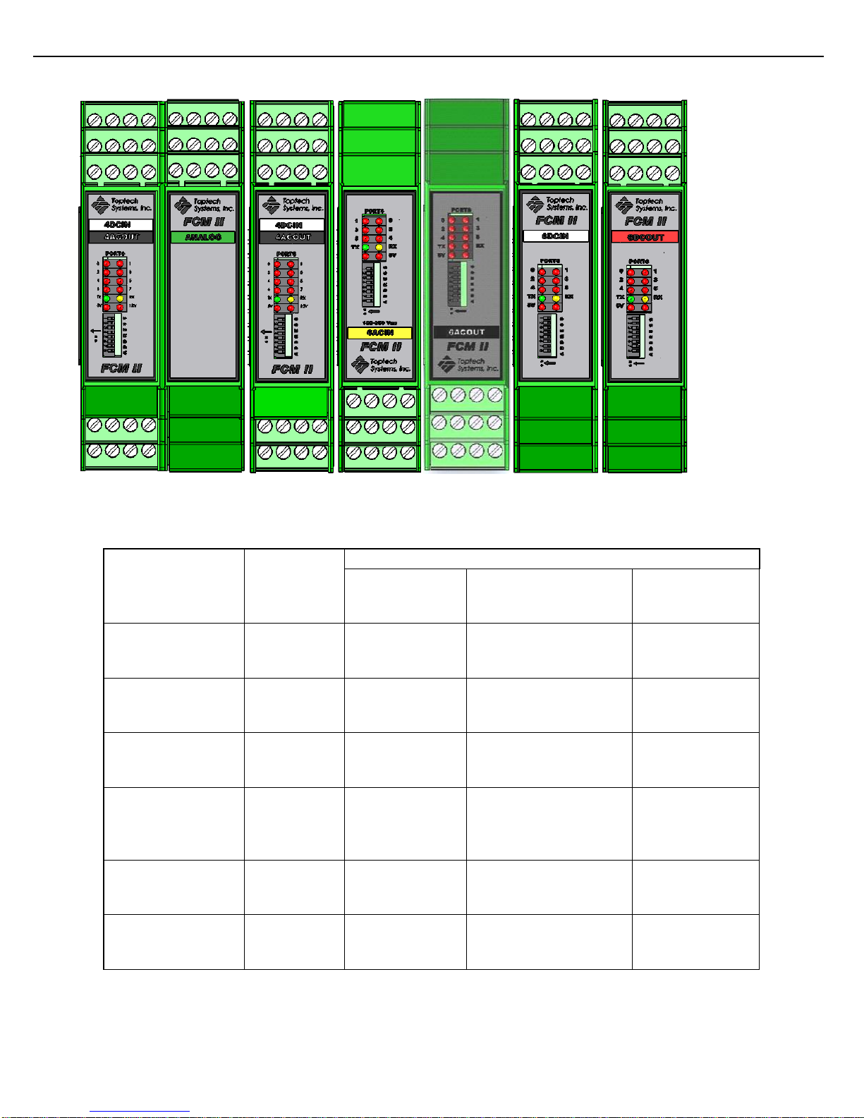
FCM II is available in six varieties (see Figures 1.1 and 1.2 below). This modular construction simplifies the
process of FCM mapping to field devices by appropriating each FCM II model with just the right amount of I/O for
its designated purpose. In addition, FCM IIs are DIN rail (35mm) mountable and require no wiring between units;
24Vdc and serial communications are bussed. This substantially simplifies installation and wiring.
FCM II Installation Guide: 20160419 - Part # 2307
Chapter 1 – General
9
Module
Supply
Voltage
Electrical Ratings
Auxiliary
Power Supply
Outputs
Inputs
FCM II 4DC IN/
4AC OUT
Min. 19 Vdc
Max. 36 Vdc
100mA Max
12 Vdc
167 mA Max
250 Vac
350 mA max.
6K Cycles, Pilot Duty
30 Vdc
SELV
Limited Energy
FCM II Analog
Min. 19 Vdc
Max. 36 Vdc
100mA Max
--
4-20 mA
SELV
Limited Energy
RTD, 4-20 mA
SELV
Limited Energy
FCM II 6 AC IN
Min. 19 Vdc
Max. 36 Vdc
100mA Max
--
--
250 Vac max.
Optically Isolated
Contact Closure
FCM II 6 AC OUT
Min. 19 Vdc
Max. 36 Vdc
100mA Max
--
250 Vac
350 mA max.
6K Cycles, Pilot Duty
--
FCM II DC IN
Min. 19 Vdc
Max. 36 Vdc
100mA Max
--
--
30 Vdc
SELV
Limited Energy
FCM II DC OUT
Min. 19 Vdc
Max. 36 Vdc
100mA Max
30 Vdc
250mA max.
6K Cycles, Pilot Duty
Figure 1.1 FCM II Module Comparison
1.4.1 ELECTRICAL RATINGS:
Figure 1.2 FCM II Module Electrical Ratings
FCM II Installation Guide: 20160419 - Part # 2307

Chapter 1 – General
10
1.4.2 OPERATING CONDITIONS:
Operating temperature (surrounding air temperature) -40°F to 140°F (-40°C to 60°C).
Environmental Ratings: None. FCM II modules are classified as open equipment must be placed in a
suitable Type 4 (or IP 65) or better enclosure.
For product outline and dimensions see Figure 6.1 and Figure 6.2.
1.5 ELECTROSTATIC DISCHARGE (ESD) PROTECTION:
The FCM II contains electronic components and assemblies subject to damage by ESD. The FCM II was
designed to protect against ESD while the unit is mounted on an electrical panel and in normal operation. Proper
handling procedures must be observed during the removal, installation, repair and other handling of FCM II
modules summarized below.
1) Service must be performed by authorized personnel only.
2) The person performing the service must be grounded by an ESD grounding strap and connected to
ground.
3) The plastic enclosures offer a degree of protection of the inner printed circuit board assemblies
against ESD. However, the heat venting slots and the wiring terminals blocks do allow a possible path
for ESD when not fastened to the electrical panel. Therefore, a servicing technician is advised to
touch unpainted metal of the electrical panel prior to installing or replacing FCM II modules.
4) FCM II modules must be placed in and transported in conductive bags or other conductive containers.
5) FCM II modules must not be removed from the conductive container until time of use.
6) All other “best” practices for protecting devices from ESD must be observed.
FCM II Installation Guide: 20160419 - Part # 2307
Chapter 2 – Installation
11
CHAPTER 2 INSTALLATION
2.1 MODULE INSTALLATION
FCM II modules are easily attached to 35mm DIN rails by tilting the top edge toward the panel and catching the
top edge on the rail (see Figure 2.1 below). Then the module is swung back down until the spring loaded metal
foot catches on the bottom edge of the rail (see Figure 2.2 below). The 24 Vdc power and RS-485
communication is connected by sliding adjacent FCM II’s together until the bus connectors click into place (see
Figure 2.3 below).
2.2 MODULE REMOVAL
Module removal is the reverse of installation. Power must be removed from the modules. Then, spread the
module to be removed from adjacent modules on either side. Disengage the spring loaded bottom catch by
inserting a ¼” Flat Head screwdriver and sliding the catch away from the rail and tilting the module top toward the
panel. With the bottom edge disconnected, the top foot may by moved off of the rail to free the module. Do not
attempt to open the module’s plastic housing.
Figure 2.1 Engage Top Foot on Rail
FCM II Installation Guide: 20160419 - Part # 2307
Figure 2.2 Snap Metal Foot to Rail

Chapter 2 – Installation
12
Figure 2.3 Slide Modules Together
2.3 FCM II PANELS AND ENCLOSURES:
2.3.1 PANEL LAYOUTS:
Toptech Systems assembles standard panel layouts which are shown in Chapter 6. These include a 20 inch by
20 inch panel with a single DIN rail of FCM IIs or a 30 inch by 30 inch panel with two DIN rails of FCM IIs.
Exterior dimensions of the panel’s associated enclosures are also shown in Chapter 6.
2.3.2 PANEL WIRING
The following guidelines are recommended when installing panels at a facility and making field connections.
1. Connect a safety ground to the panel. A copper post is provided for this.
2. Wiring must enter the enclosure through conduit entries. All conduits must be terminated at the enclosure
by use of appropriately rated conduit hubs or glands.
3. Avoid routing AC and DC wiring in the same conduit in order to minimize the disruption of DC and analog
voltage circuits by line voltage transients and surges.
4. Wiring must comply with all local electrical codes.
2.3.3 ENCLOSURE MOUNTING
Mounting instructions are provided with all panel assemblies shipped by Toptech. Whether installing a Toptech
supplied FCM II enclosure, or installing a customer sourced enclosure, follow the manufacturer’s mounting
instructions in order not to invalidate regulatory requirements.
FCM II Installation Guide: 20160419 - Part # 2307
Chapter 2 – Installation
13
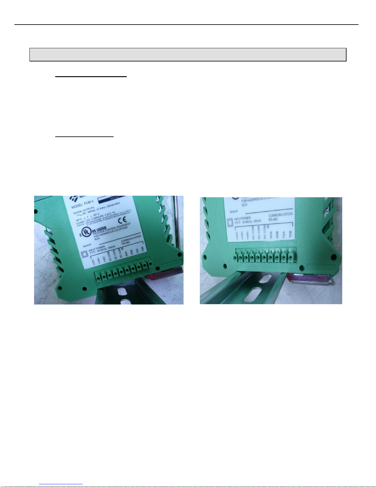
2.4 ELECTRICAL SUPPLY CONNECTIONS
FCM IIs require a supply of 19 – 36 Vdc, 100mA to power each module (200mA for a double). The power must
be from an isolated, SELV (Safety Extra Low Voltage) power supply, rated 36 VDC max.
Although the ten position power/communication bus terminal block is rated for solid or stranded copper wire 14 to
30 AWG [2.1 to 0.05 mm2], Toptech recommends using stranded 16 to 18 AWG [1.3 to 0.8 mm2] for power. See
section 2.5 regarding the choice of communication wire. The required screw tightening torque is 2 to 4 Lb-in. [0.2
to 0.5 Nm]. For terminal assignments, see Figure 2.4 below. Wires must be stripped ¼” and inserted into terminal
block leaving no bare conductor exposed. Only one of each of the three possible 24 VDC+/DC COMMON pairs
need be used; the rest are provided for bus capacity.
24 VDC + 24 VDC +
24 VDC + 24 VDC +
24 VDC + 24 VDC +
DC Common DC Common
DC Common DC Common
DC Common DC Common
RDA RDA
RDB RDB
TDA TDA
TDB TDB
Figure 2.4 Power / Com Connection Bus
FCM II Installation Guide: 20160419 - Part # 2307
Chapter 2 – Installation
14
!
!
Note 1: If a disconnecting device is used, ensure that it is not blocked by FCMs or any other
device which would make it difficult to operate. If used, do not place the disconnect in a
Class I, Division 2 location.
Note 2: Do not place a thermal magnetic circuit breaker in a Class I, Division 2 location.
The installer should provide over current protection between the branch circuit and the supply according to the
power supply manufacturer’s recommendations; usually either an appropriately sized s low-blow fuse or a
characteristic B thermal magnetic circuit breaker. Because the primary side of the power supply is overcurrent
protected, it is not necessary to fuse the 24 Vdc output, unless it is used to supply power to field devices located
outside of the panel housing the FCM IIs.
2.5 SERIAL COMMUNICATION CONNECTION
RS-422/485 communications protocol is designed for multi-point (i.e. computer to multiple devices, also called
multi-dropped) communications up to 4,000 feet (1,220 Meters).
RS-422 requires 4-wires (2 twisted pair) for full duplex communications and utilizes a transmit pair of wires (TDA
& TDB) and a receive pair of wires (RDA & RDB).
Figure 2.4 shows the terminal assignments for the bus RS-485 serial connection. Either end may be connected
to a MultiLoad or other serial device as the bus supplies the serial connection to all modules that are joined
together. The TD and RD pairs are swapped at the MultiLoad II. Although the ten position terminal block is rated
for 14 to 30 AWG [2.1 to 0.05 mm2], a reliable serial connection will be achieved by the use of cable meeting the
following:
24 AWG [0.2 mm2] stranded.
4-wire, two twisted pair with overall shield.
30 pF maximum between conductors.
1,000 ohm impedance.
Maximum length: 4,000 feet (1,220 Meters)
Maximum stub length: 15 feet.
All exposed shields must be properly insulated to prevent short circuits.
All shields must be continuous, soldered and properly insulated.
FCM II Installation Guide: 20160419 - Part # 2307

Chapter 2 – Installation
15
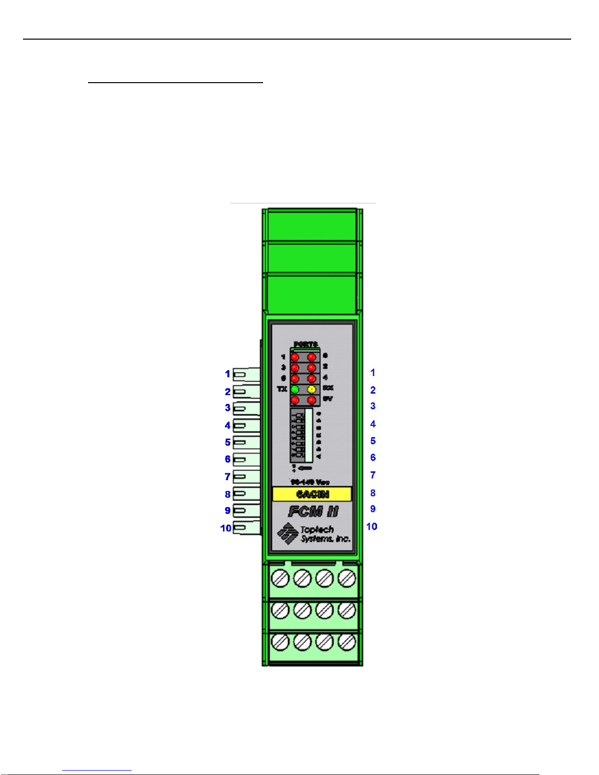
2.6 DEVICE ADDRESS CONFIGURATION
Figure 2.5 shows the locations of I/O, power, and communication status indicators and the location of DIP
switches used to set the module’s serial address. The table below provides the settings for FCM addresses 0 –
31.
Port 0 Status Port 1 Status
Port 2 Status Port 3 Status
Port 4 Status Port 5 Status
Port 6 Status Port 7 Status
TX Status RX Status
FCM 5V Power FCM 12V Output
FCM Address
Dip Switches
Figure 2.5 Module Status, Configuration Setting and Identification
FCM II Installation Guide: 20160419 - Part # 2307

Chapter 2 – Installation
16
FCM
Address
Dip Switch Settings
8 7 6 5 4 3 2
1
0
0 0 0 0 0 0 0 0 1
0 0 0 0 0 0 0
1 2 0 0 0 0 0 0 1
0
3
0 0 0 0 0 0 1
1 4 0 0 0 0 0 1 0 0 5
0 0 0 0 0 1 0
1
6
0 0 0 0 0 1 1
0 7 0 0 0 0 0 1 1 1 8
0 0 0 0 1 0 0
0 9 0 0 0 0 1 0 0
1
10
0 0 0 0 1 0 1
0
11
0 0 0 0 1 0 1 1 12
0 0 0 0 1 1 0
0
13
0 0 0 0 1 1 0
1
14
0 0 0 0 1 1 1
0
15
0 0 0 0 1 1 1 1 16
0 0 0 1 0 0 0
0
17
0 0 0 1 0 0 0
1
18
0 0 0 1 0 0 1
0
19
0 0 0 1 0 0 1
1
20
0 0 0 1 0 1 0
0
21
0 0 0 1 0 1 0
1
22
0 0 0 1 0 1 1
0
23
0 0 0 1 0 1 1 1 24
0 0 0 1 1 0 0
0
25
0 0 0 1 1 0 0
1
26
0 0 0 1 1 0 1
0
27
0 0 0 1 1 0 1 1 28
0 0 0 1 1 1 0
0
29
0 0 0 1 1 1 0
1
30
0 0 0 1 1 1 1
0
31
0 0 0 1 1 1 1
1
0=Off (switch to the right), 1=On (switch to the left)
Figure 2.6 DIP Switch Configuration Settings
2.7 SWING ARMS
An industry practice of sharing loading equipment between two adjacent lanes is termed a “swing arm.” The
reference indicates the actual practice in which one load arm can be swung from one side of a loading bay to
another. To achieve this, the FCM II controlling the I/O associated with that field equipment must have its
communication switched between the MutliLoad II on each lane, depending on which lane the load arm resides
when in use. This communication is switched via a four pole relay and the ring switch attached to the swing arm
FCM II Installation Guide: 20160419 - Part # 2307

Chapter 2 – Installation
17
Be aware of device addressing and ensure that duplicate addresses do not exist. The addresses
of shared FCM IIs must not be duplicated in either bay.
Control of the relay coils is to be wired by the customer to the arm ring switch. Note the voltage
available and match it to the relay coil voltage rating. If DC voltage is used, a reverse biased diode
is recommended to snub ringing voltage when the coil opens.
Although star wiring of FCM IIs is discouraged, star wiring of the shared modules is necessary
since switching of shared upstream modules would remove the connectivity of one of the
communication lines from the downstream modules in a daisy chain configuration.
is used to energize or de-energize that relay. Figure 2.7 shows the wiring required to achieve this. The following
guidelines are suggested.
Figure 2.7 Swing Arm Wiring of Shared FCM IIs
FCM II Installation Guide: 20160419 - Part # 2307

Chapter 3 – Field Wiring
18
Note that the ANALOG board is factory assembled with a 4DCIN/4ACOUT module into a double
wide configuration. It is not possible to use the analog module as a single module, nor should the
analog board be disconnected from its attached 4DCIN/4ACOUT module.
CHAPTER 3 FIELD WIRING
3.1 CONNECTION REQUIREMENTS
Although each right angle, four position terminal block is rated for the use of solid or stranded copper 12 to 30
AWG [3.3 to 0.05 mm2], Toptech recommends using stranded copper wire 12 AWG to 24 AWG [3.3 to 0.2 mm2]
depending on the type of field device. The required screw tightening torque is 5 to 7 Lb-in. [0.6 to 0.8 Nm]. Wires
must be stripped ¼” and inserted into terminal block. Details concerning field wiring terminal assignments are
given later in this chapter.
3.2 FCM II FIELD DEVICE CONNECTIONS
FCM II consists of 6 different module types (see Electrical Ratings in section 1.1.1):
1. 4DCIN/4ACOUT: 4 DC Inputs (5-30 VDC), 4 AC Outputs (12-250 VAC),
12 Vdc Power Supply, 167 mA Max
2. 6ACIN: 6 AC Input (90-140 VAC) or (180-250 VAC)
3. 6ACOUT: 6 AC Outputs (12-250VAC)
4. 6DCIN: 6 DC Inputs (5-30 VDC)
5. 6DCOUT: 6 DC Outputs (0-30 VDC)
6. ANALOG/4DCIN/4ACOUT: RTD Input, 4-20mA Input, 4-20mA Out,
4 DC Inputs (5-30 VDC), 4 AC Outputs (12-250 VAC)
FCM II Installation Guide: 20160419 - Part # 2307

Chapter 3 – Field Wiring
19
Figure 3.1 FCM II Single And Double Module Comparison
3.2.1 TERMINAL IDENTIFICATION
All DC Field Wiring Connections
Power/COM Connection Bus Power/COM Connection Bus
All AC Field Wiring Connections
Figure 3.2 FCM II Field Wiring Terminal Locations
FCM II Installation Guide: 20160419 - Part # 2307

Chapter 3 – Field Wiring
20
Gnd/Overfill Switched
Line
N.O. Digital
Valve
Solenoid
N.C. Digital
Valve
Solenoid
Neutral
Meter
Pulser
12V +
Gnd
Pulse A
(Optional)Pulse B
Port 2 Output
Port 3 Output
Port 4 Input
Port 5 Input
Caution: Line voltage used to drive the Digital Valve
Solenoids MUST be controlled by the Ground/Overfill
monitor.
In the event of a Ground loss or Overfill detection, this
voltage must be switched off to ensure a failsafe
shutdown of the product flow.
- - + +
D4 D3 D2 D1
12Vdc
Top Side
Bottom Row
- + - +
E4 E3 E2 E1
() ()
Top Side
Middle Row
Port 5
Port 4
In Out In Out
A1 A2 A3 A4
Bottom Side
Bottom Row
Port 0
Port 1
In Out In Out
B1 B2 B3 B4
Bottom Side
Middle Row
Port 3
Port 2
A
B
E
D
F
Terminal
Number
- + - +
F4 F3 F2 F1
Top Side
Top Row
Port 7
Port 6
1234
1 2 3 4
3.2.2 FLOW METER AND CONTROL VALVE WIRING
Figure 3.3 FCM II Field Wiring: Flow Meter and Control Valve
FCM II Installation Guide: 20160419 - Part # 2307

Chapter 3 – Field Wiring
21
Line
#3 Additive
Valve
Solenoid
#4 Additive
Valve
Solenoid
Neutral
12V+
Gnd
#1 Additive
Valve
Solenoid
#2 Additive
Valve
Solenoid
#1 Additive
Meter Pulser
or Switch
#2 Additive
Meter Pulser
or Switch
#3 Additive
Meter Pulser
or Switch
#4 Additive
Meter Pulser
or Switch
Port 0 Output
Port 1 Output
Port 3 Output
Port 2 Output
Port 7 Input
Port 6 Input
Port 5 Input
Port 4 Input
12V+
Gnd
- - + +
D4 D3 D2 D1
12Vdc
Top Side
Bottom Row
In Out In Out
B1 B2 B3 B4
Bottom Side
Middle Row
Port 3
Port 2
A
B
E
D
F
Terminal
Number
- + - +
E4 E3 E2 E1
Top Side
Middle Row
Port 5
Port 4
- + - +
F4 F3 F2 F1
Top Side
Top Row
Port 7
Port 6
In Out In Out
A1 A2 A3 A4
Bottom Side
Bottom Row
Port 0
Port 1
1234
1 2 3 4
3.2.3 ADDITIVE WIRING
Note: Most additive injection meters only provide an Open-Collector (pull down) type output. Typically a 1,000
Ohm, ¼ watt pull-up resistor needs to be added in the pulser junction box to pull this output to 12V+ when the
output is off.
Figure 3.4 FCM II Field Wiring: Additive Meters and Injection Valves
FCM II Installation Guide: 20160419 - Part # 2307

Chapter 3 – Field Wiring
22
White
4-Wire
100 Ohm Platium RTD
Alpha = 0.0385
Note: All 4 wires MUST be run to the
sensor. Do not simply jumper REF- to
COM or REF+ to V+ at the FCM II.
For 3-wire and 2 wire probes, the
connection of REF- to COM and REF+ to
V+ should be as close as possible to the
probe (within inches).
White
Red
Red
White
Red
2-Wire RTD Connection
White
Red
3-Wire RTD Connection
Red
Com R- R+ V+
D4 D3 D2 D1
RTD
Top Side
Bottom Row
NC NC I- I+
E4 E3 E2 E1
Top Side
Middle Row
4-20 mA IN
Iout Rtn Com V+
F4 F3 F2 F1
Top Side
Top Row
4-20 mA OUT
E
D
F
Terminal
Number
1234
1 2 3 4
1234
3.2.4 RTD TEMPERATURE PROBE WIRING
FCM II Installation Guide: 20160419 - Part # 2307
Figure 3.5 FCM II Field Wiring: RTD

Chapter 3 – Field Wiring
23
4-20mA Transmitter
+
-
Iout Rtn Com V+
F4 F3 F2 F1
Top Side
Top Row
4-20 mA OUT
Terminal
Number
Com R- R+ V+
D4 D3 D2 D1
RTD
Top Side
Bottom Row
NC NC I- I+
E4 E3 E2 E1
Top Side
Middle Row
4-20 mA IN
E
D
F
1234
1 2 3 4
1234
External Power Supply
(+)(-)
I
3.2.5 4-20MA INPUT WIRING: LOOP CURRENT PROVIDED BY EXTERNAL POWER SUPPLY
NOTE: The receiver does not contain a voltage source. The loop must be powered either by the transmitter or by
Figure 3.6 FCM II Field Wiring: 4-20mA Input
an external power supply. The I/O Board adds 75 Ohms to the loop.
FCM II Installation Guide: 20160419 - Part # 2307

Chapter 3 – Field Wiring
24
Iout Rtn Com V+
F4 F3 F2 F1
Top Side
Top Row
4-20 mA OUT
Terminal
Number
Com R- R+ V+
D4 D3 D2 D1
RTD
Top Side
Bottom Row
NC NC I- I+
E4 E3 E2 E1
Top Side
Middle Row
4-20 mA IN
E
D
F
1234
1 2 3 4
1234
External Power Supply
(+)(-)
I
I-
I+
4-20mA Transmitter
V+
V-
3.2.6 4-20MA INPUT WIRING: LOOP CURRENT PROVIDED BY TRANSMITTER
Figure 3.7 FCM II Field Wiring: 4-20mA Input
NOTE: The receiver does not contain a voltage source. The loop must be powered either by the transmitter or by
an external power supply. The I/O Board adds 75 Ohms to the loop.
FCM II Installation Guide: 20160419 - Part # 2307

Chapter 3 – Field Wiring
25
4-20mA Receiver
+
-
Note: The 4-20mA output requires a
power source (12-30vdc). The 12vdc
output can be used as shown here.
Com R- R+ V+
D4 D3 D2 D1
RTD
Top Side
Bottom Row
NC NC I- I+
E4 E3 E2 E1
Top Side
Middle Row
4-20 mA IN
Iout Rtn Com V+
F4 F3 F2 F1
Top Side
Top Row
4-20 mA OUT
Terminal
Number
E
D
F
E
D
F
- - + +
D4 D3 D2 D1
Top Side
Bottom Row
12Vdc
- + - +
E4 E3 E2 E1
Top Side
Middle Row
Port 5
Port 4
- + - +
F4 F3 F2 F1
Top Side
Top Row
Port 7
Port 6
1234
1 2 3 4
1234
3.2.7 4-20MAOUTPUT WIRING
Figure 3.8 FCM II Field Wiring: 4-20mA Output
FCM II Installation Guide: 20160419 - Part # 2307

Chapter 3 – Field Wiring
26
Line
Block Valve
Status
VRU/VCU
Neutral
Ground/
Overfill
ESD
Note: This shows a typical configuration.
AC Permissive/Status inputs can be
assigned to any unused AC inputs.
Pump
Status
Etc.
Port 5 Input
Port 4 Input
Port 3 Input
Port 2 Input
Port 1 Input
Port 0 Input
Caution: The 6ACIN module is available
in 90-140 VAC and 180-250 VAC
models.
VERIFY MODULE VOLTAGE LISTED!!!
L N L N
A1 A2 A3 A4
Bottom Side
Bottom Row
Port 0
Port 1
L N L N
B1 B2 B3 B4
Bottom Side
Middle Row
Port 2
Port 3
L N L N
C1 C2 C3 C4
Bottom Side
Top Row
Port 4
Port 5
Terminal
Number
1 2 3 4
3.2.8 AC PERMISSIVE/STATUS WIRING (6ACIN)
Figure 3.9 FCM II Field Wiring: AC Permissive/Status (6ACIN)
FCM II Installation Guide: 20160419 - Part # 2307

Chapter 3 – Field Wiring
27
Component 1
Pump Run
Component 2
Pump Run
Component 3
Pump Run
Additive
Pump Run
Block Valve 1
Open
Block Valve2
Open
Line
Neutral
Note: This shows a typical configuration.
AC ouputs can be assigned to any
unused AC outputs.
In Out In Out
A1 A2 A3 A4
Bottom Side
Bottom Row
Port 0
Port 1
In Out In Out
B1 B2 B3 B4
Port 3
Port 2
Bottom Side
Middle Row
In Out In Out
B1 B2 B3 B4
Bottom Side
Top Row
Port 4
Port 5
A
B
C
Terminal
Number
1 2 3 4
3.2.9 AC OUTPUT WIRING (6ACOUT)
Figure 3.10 FCM II Field Wiring: AC Pump and Valve Control (6ACOUT)
FCM II Installation Guide: 20160419 - Part # 2307

Chapter 3 – Field Wiring
28
5-30 Vdc
Power
Block Valve
Status
VRU/VCU
Common
Ground/
Overfill
ESD
Note: This shows a typical configuration.
DC Permissive/Status inputs can be
assigned to any unused DC inputs.
Pump
Status
Etc.
Port 0 Input
Port 1 Input
Port 2 Input
Port 3 Input
Port 4 Input
Port 5 Input
Terminal
Number
E
D
F
- + - +
D4 D3 D2 D1
Top Side
Bottom Row
Port 1
Port 0
- + - +
E4 E3 E2 E1
Top Side
Middle Row
Port 3
Port 2
- + - +
F4 F3 F2 F1
Top Side
Top Row
Port 5
Port 4
1234
3.2.10 DC PERMISSIVE/STATUS WIRING (6DCIN)
Figure 3.11 FCM II Field Wiring: DC Permissive/Status (6DCIN)
FCM II Installation Guide: 20160419 - Part # 2307

Chapter 3 – Field Wiring
29
5-30 Vdc
Power
VRU/VCU
Common
Ground/
Overfill
ESD
Note: This shows a typical configuration.
DC Permissive/Status inputs can be
assigned to any unused DC inputs.
Etc.
Port 4 Input
Port 5 Input
Port 6 Input
Port 7 Input
Note: Ports 4-7 can be used for general DC inputs when not configured for additive or component
meter input.
L N L N
A1 A2 A3 A4
Bottom Side
Bottom Row
Port 0
Port 1
L N L N
B1 B2 B3 B4
Bottom Side
Middle Row
Port 2
Port 3
A
B
E
D
F
Terminal
Number
- - + +
D4 D3 D2 D1
Top Side
Bottom Row
12Vdc
- + - +
E4 E3 E2 E1
Top Side
Middle Row
Port 5
Port 4
- + - +
F4 F3 F2 F1
Top Side
Top Row
Port 7
Port 6
1234
1 2 3 4
3.2.11 DC PERMISSIVE/STATUS WIRING (4DCIN/4ACOUT)
Figure 3.12 FCM II Field Wiring: DC Input (4DCIN/4ACOUT)
FCM II Installation Guide: 20160419 - Part # 2307

Chapter 3 – Field Wiring
30
Line
Port 3 Output
Open Block
Valve
Neutral
Component
Pump Run
Additive
Pump Run
Note: This shows a typical configuration.
AC ouputs can be assigned to any
unused AC outputs.
Etc.
Port 0 Output
Port 1 Output
Port 2 Output
Note: Ports 0-3 can be used for general
AC outputs when not configured for
additive or digital valve control.
- - + +
D4 D3 D2 D1
Top Side
Bottom Row
12Vdc
A
B
E
D
F
Terminal
Number
- + - +
E4 E3 E2 E1
Top Side
Middle Row
Port 5
Port 4
- + - +
F4 F3 F2 F1
Top Side
Top Row
Port 7
Port 6
In Out In Out
A1 A2 A3 A4
Bottom Side
Bottom Row
Port 0
Port 1
In Out In Out
B1 B2 B3 B4
Port 3
Port 2
Bottom Side
Middle Row
1234
1 2 3 4
3.2.12 AC OUTPUT WIRING (4DCIN/4ACOUT)
Figure 3.13 FCM II Field Wiring: AC Output (4DCIN/4ACOUT)
FCM II Installation Guide: 20160419 - Part # 2307

Chapter 3 – Field Wiring
31
5-30 Vdc
Power
Open Block
Valve
Bay Active
Common
Component
Pump Run
Additive
Pump Run
Note: This shows a typical configuration.
DC ouputs can be assigned to any
unused DC outputs. Any DC output port
can be configured as an output pulse
Pulse Out
Etc.
Port 0 Output
Port 1 Output
Port 2 Output
Port 3 Output
Port 4 Output
Port 5 Output
E
D
F
Terminal
Number
In Out In Out
D4 D3 D2 D1
Top Side
Bottom Row
Port 1
Port 0
In Out In Out
E4 E3 E2 E1
Top Side
Middle Row
Port 3
Port 2
In Out In Out
F4 F3 F2 F1
Top Side
Top Row
Port 5
Port 4
1234
3.2.13 DC OUTPUT WIRING (6DCOUT)
Figure 3.14 FCM II Field Wiring: DC Output (6DCOUT)
FCM II Installation Guide: 20160419 - Part # 2307

Chapter 3 – Field Wiring
32
Gnd/Overfill Switched
Line
N.O. Digital
Valve
Solenoid
N.C. Digital
Valve
Solenoid
Port 2 Output
Port 3 Output
Air Purge
Valve
Solenoid
Top Float Switch
Bottom Float Switch
Neutral
High
Low
Not Low Low
Air Eliminator
Neutral
Note 2: Port 1 configured as Alt. High Flow Rate Inversed. When this signal is removed,
the flow rate will drop to the Alt. High Flow Rate.
Note 1: When the level drops below Low Low, the power will be removed from the digital
valves, stopping flow before the air eliminator is completely drained.
L N L N
A1 A2 A3 A4
Bottom Side
Bottom Row
Port 0
Port 1
L N L N
B1 B2 B3 B4
Bottom Side
Middle Row
Port 2
Port 3
L N L N
C1 C2 C3 C4
Bottom Side
Top Row
Port 4
Port 5
A
B
Terminal
Number
A
B
C
In Out In Out
A1 A2 A3 A4
Bottom Side
Bottom Row
Port 0
Port 1
In Out In Out
B1 B2 B3 B4
Bottom Side
Middle Row
Port 2
Port 3
1 2 3 4 1 2 3 4
3.2.14 3 OUTPUT AIR ELIMINATOR WIRING
Figure 3.15 FCM II Field Wiring: 3 Output Air Eliminator
FCM II Installation Guide: 20160419 - Part # 2307

Chapter 3 – Field Wiring
33
Gnd/Overfill
Switched
Line
N.O. Digital
Valve
Solenoid
N.O. Digital
Valve
Solenoid
Neutral
Port 2 Output
Port 3 Output
Air Purge
Valve
Solenoid
Top Float Switch
Neutral
High
Low
Air Eliminator
Note 2: With only two states returned from the air eliminator, flow must be completely stopped to
purge air.
To purge air by only slowing the rate, a 3 output air eliminator head must be used.
Note 1: When the level drops below Low, the power will be removed from the digital valves, stopping
flow before the air eliminator is completely drained.
A
B
Terminal
Number
In Out In Out
A1 A2 A3 A4
Bottom Side
Bottom Row
Port 0
Port 1
In Out In Out
B1 B2 B3 B4
Bottom Side
Middle Row
Port 2
Port 3
1 2 3 4
3.2.15 2 OUTPUT AIR ELIMINATOR WIRING
Figure 3.16 FCM II Field Wiring: 2 Output Air Eliminator
FCM II Installation Guide: 20160419 - Part # 2307

Chapter 3 – Field Wiring
34
Counter Increment
Pulses (White)
Counter Reset Pulse
(Green)
E
D
F
1234
Ground/Common (Black)
- + - +
E4 E3 E2 E1
Top Side
Middle Row
Port 5
Port 4
- + - +
F4 F3 F2 F1
Top Side
Top Row
Port 7
Port 6
E
D
F
1234
+12VDC (Red)
(Output Pulse Port)
(Batch Authorized Inverse Port)
MODEL: E1613
Note:
1. Use only model E1613.
External
Power Supply
(-)(+)
Terminal
Number
3.2.16 LECTRO COUNT REMOTE DISPLAY WIRING
Figure 3.17 FCM II Field Wiring: Lectro Count Remote Display
FCM II Installation Guide: 20160419 - Part # 2307

Chapter 4 – Simulation
35
!
Do not make connections to field terminals. UNEXPECTED OPERATION MAY RESULT. The I/O
is close looped in logic.
CHAPTER 4 SIMULATION
The FCM II simulator is a special version of an FCM II 4DCIN, 4ACOUT module. The FCM II simulator differs
from an FCM 1 simulator in that it is configured entirely from MultiLoad (no keyboard or display required). This
simulator is able to perform most all of the FCM I simulator functions with the exception of forcing error conditions
and looping back outputs to inputs. Loopbacks may be wired externally however.
4.1 METER SIMULATION
Product flow control loops can be run in a demonstration mode by imitating a “virtual” flow meter (single or
quadrature) and its associated “virtual” Digital Control Valve. Product flow simulation is automatically enabled
when a meter is assigned to the simulator. Ports 2 and 3 will be automatically assigned and actuated to simulate
the upstream and downstream solenoids of an associated Digital Control valve. Port 4 will be assigned as the
primary meter pulser and the module will behave as if pulses were actually received on Port 4. A quadrature
meter will be simulated if the 'Quad Check Enable' parameter is set in MultiLoad and the secondary meter
channel will be assigned to Port 5.
When ports 2 & 3 are both activated product flow will ramp up. When port 2 is active and port 3 is inactive, flow
will remain constant. When both ports are inactive, flow rate will ramp down to zero.
4.2 ADDITIVE SIMULATION
Up to 4 channels of additive control (Solenoid or Piston type) may also be simulated. If an additive meter is
selected, it will be simulated with a 100 Hz pulser input.
4.3 ANALOG SIMULATION
If analog functions are enabled in MultiLoad such as RTD temperature input, or 4-20mA current input, the
simulator places fixed analog values into these input registers. For the RTD, the fixed temperature is 28.5°C. For
the 4-20mA current input the value is fixed at 12.800mA. The later input provides simulation of a density or
pressure sensor input.
4.4 GENERIC I/O SIMULATION
I/O lines not used for Product or Additive simulation are available as general purpose DC inputs or AC outputs.
FCM II Installation Guide: 20160419 - Part # 2307

Chapter 5 – Troubleshooting
36
CHAPTER 5 TROUBLESHOOTING
Port 0 Status Port 1 Status
Port 2 Status Port 3 Status
Port 4 Status Port 5 Status
Port 6 Status Port 7 Status
TX Status RX Status
FCM 5V Power FCM 12V Output
FCM Address
Dip Switches
Figure 5.1 FCM II Module Front Panel
5.1 IS THE MODULE POWERED?
All standalone FCM II modules have a front panel LED that shows the power status of its 5V power. In addition,
the 4DCIN/4ACOUT module has a 12V indicator LED showing the status of its onboard 12 Vdc supply used to
power field device dc inputs. The modules must be powered from the BUS rail with a DC voltage source of 19 –
36 Vdc. If required, verify the output voltage and current capacity of the power supply used to power the FCM IIs.
5.2 IS THE MODULE COMMUNICATING?
The quickest check that an FCM II module is communicating with a MultiLoad or other serial device is to look for
the module’s front panel TX LED to flash. The RX LED on all modules will flash when the MultiLoad or other line
master sends a message to any multidropped FCM.
For a more in depth communication status indication, the MultiLoad’s Diagnostic Menu may be used. This menu
is accessible from within the MultiLoad’s configuration mode.
1) Enter program mode by pressing 00000 on the keypad, then press Next key.
2) Select diagnostics from main menu.
FCM II Installation Guide: 20160419 - Part # 2307

Chapter 5 – Troubleshooting
37
D I A G N O S T I C S M E N U
Next Prev Exit Enter
004 FCM COM DIAGNOSTICS
Exit
3) Select FCM COM
Card Reader Meters
COM Loopback Components
Serial Ports Additives
Network Test Custom Logic
Keypad
Display
Unicode
FCM Com
PCM Com
FCM Health
PCM Health
RCU
Bay
Preset
00-Ok
01-Ok
02-Ok
4) If screen display is the same as above, the FCM IIs are communicating with the MultiLoad II.
5) If an FCM II is not communicating, the message XX-ERR appears where XX is the address of the FCM that is
not communicating.
6) For a log of the occurances of dropped communications (including the registration as com loss when the
module has been powered down), select the menu option FCM HEALTH.
Should a module have a “ERR” state, double check that the device address has been set correctly and that two
devices do not share a duplicate address. If all modules have an “ERR” state, check the bus communication
wiring (see section 2.5).
5.3 ARE THE INPUTS FUNCTIONING?
An input LED will only illuminate when a voltage of 5 – 30 Vdc appears across the input’s terminal pair. If a
problem occurs, verify the wiring shown in chapter 3.
5.4 ARE THE OUTPUTS FUNCTIONING?
The output LED will illuminate in response to an output commanded on. If necessary, check the output terminal
with a voltmeter.
FCM II Installation Guide: 20160419 - Part # 2307

Chapter 5 – Troubleshooting
38
PRE #1 MTR #1 TEMPERATURE
Temperature Unadjusted: -1.87C
[1]Temperature Offset: +0.00C
[2]Temperature Adjusted: -1.87C
Next Prev Exit
5.5 ARE RTD ERRORS PRESENT?
Selecting Temperature from the “Views and Inquiries” menu allows for viewing of each meter’s temperature
grouped by preset. At the meter level, the screen below is available. The normal message on the fifth line is
“Status OK.” In event of an error, there are two messages:
Probe Error: The probe is faulty, there is a wire break, or no cable connection.
Module Has Bad AD Converter: Damage of the electronics within the RTD analog circuitry has occurred.
The unit must be returned to Toptech for repair or replacement.
Status Ok
5.6 ARE OTHER ERRORS PRESENT?
Please consult the MultiLoad User Manual for further errors that are not covered here. The MultiLoad User
Manual describes in great detail how to configure an FCM II panel for most kinds of control applications as well as
how to troubleshoot those setups.
5.7 IS TECHNICAL ASSISTANCE AVAILABLE?
Technical assistance may be obtained during business hours (or during extended hours by arrangement) from
Toptech System’s Support Department by dialing 407-332-1774 x381 or x382.
In Europe, assistance may be obtained during business hours (or during extended hours by arrangement) from
Toptech Europe by dialing +32 (0)3 250 60 60.
FCM II Installation Guide: 20160419 - Part # 2307

Chapter 6 – Dimensions, Panel Layouts, Wiring
39
CHAPTER 6 DIMENSIONS, PANEL LAYOUTS, WIRING SUGGESTIONS
6.1 MODULE DIMENSIONS
Figure 6.1 FCM II Single Module Dimensions
FCM II Installation Guide: 20160419 - Part # 2307

Chapter 6 – Dimensions, Panel Layouts, Wiring
40
Figure 6.2 FCM II Double Module Dimensions
FCM II Installation Guide: 20160419 - Part # 2307

Chapter 6 – Dimensions, Panel Layouts, Wiring
41
The maximum number of FCM IIs on this panel is the equivalent of 12 single wide modules.
Toptech recommends mounting the power supply on the DIN rail with the FCM IIs as most DIN rail
power supplies require vertical mounting and top/bottom clearance for proper cooling.
6.2 STANDARD PANEL DIMENSIONS
6.2.1 20 INCH X 20 INCH PANEL
Figure 6.3 20 Inch x 20 Inch Panel Layout
FCM II Installation Guide: 20160419 - Part # 2307

Chapter 6 – Dimensions, Panel Layouts, Wiring
42
Figure 6.4 20 Inch x 20 Inch Enclosure Dimensions
FCM II Installation Guide: 20160419 - Part # 2307

Chapter 6 – Dimensions, Panel Layouts, Wiring
43
The maximum number of FCM IIs on this panel is the equivalent of 18 single wide modules per row
(36 total).
Toptech recommends mounting the power supply on the DIN rail with the FCM IIs as most DIN rail
power supplies require vertical mounting and top/bottom clearance for proper cooling.
Each row of FCM IIs requires its own power supply.
6.2.2 30 INCH X 30 INCH PANEL
Figure 6.5 30 Inch x 30 Inch Panel Layout
FCM II Installation Guide: 20160419 - Part # 2307

Chapter 6 – Dimensions, Panel Layouts, Wiring
44
Figure 6.6 30 Inch x 30 Inch Enclosure Dimensions
FCM II Installation Guide: 20160419 - Part # 2307

Chapter 6 – Dimensions, Panel Layouts, Wiring
45
6.3 PANEL ELECTRICAL WIRING SUGGESTIONS
6.3.1 POWER AND COMMUNICATION DISTRIBUTION
FCM II modules were designed to minimize 24 Vdc input power and serial communication wiring by employing a
distribution buss in the base of the modules. Therefore, considerations only have to be made as to which side of
a DIN rail assembly the power and communication cable should attach (left side female plug or right side male
plug). Note also that star wiring should be avoided, so communication cable extension to adjacent rows ought to
use the opposite end of the joined modules than the end from which communication enters.
Toptech also recommends using one power supply for each DIN rail assembly. See Figures 6.7 to 6.9 for the
various configurations of FCM II power and serial communication wiring schematics.
Figure 6.7 FCM II Power and Serial Communication Panel Wiring: Single Row
FCM II Installation Guide: 20160419 - Part # 2307

Chapter 6 – Dimensions, Panel Layouts, Wiring
46
Figure 6.8 FCM II Power and Serial Communication Panel Wiring: Two Rows, Two Serial Ports
FCM II Installation Guide: 20160419 - Part # 2307

Chapter 6 – Dimensions, Panel Layouts, Wiring
47
Figure 6.9 FCM II Power and Serial Communication Panel Wiring: Two Rows, One Serial Port
6.3.2 WIRING TERMINAL IDENTIFICATION
Figure 6.10 shows the terminal block labeling of field connections. All modules follow the convention of labeling
bottom side plugs from A to C as the staircase to the top and D to F for the top side plugs as they staircase to the
top. Numbers one through 4 are arranged from left to right when viewing the plug from its wire entry side. To
differentiate terminals of different modules, Toptech recommends a module.slot.number identification scheme
where
module is the FCM’s address,
slot is either 0 or 1 depending on whether the terminals are attached to the left or right board in a double wide
housing, and
number is the terminal A to F, 1 to 4.
As an example, an ANALOG/4DCIN/4ACOUT module at address 0, would have its Port 0 line voltage terminal
labeled 0.0.A1 and the loop voltage for the RTD would be labeled 0.1.D1. See Figure 3.5.
FCM II Installation Guide: 20160419 - Part # 2307

Chapter 6 – Dimensions, Panel Layouts, Wiring
48
!
Note: Do not use FCM II ac outputs to directly run pumps. Use an interposing relay. The
rated currents of the ac output modules should be sufficient for most types of solenoid
valves but note the ratings as shown in Figure 1.2 and section 3.2.
Figure 6.10 FCM II Field Terminal Block Labels
6.3.3 VOLTAGE DISTRIBUTION
The common practice of installing a MultiLoad panel usually involves bringing all field devices directly into the
enclosure. But note that DC and AC output modules only switch the voltage and do not distribute Neutral or dc
common voltages. For this reason, Toptech recommends the installation of bussed DIN mounted terminal blocks
to distribute Neutrals and dc commons.
Two ac line voltages are also distributed through the panels. One is normal 120V line voltage switched to additive
injectors, motor operated valves, VRU/VCOs, and pump run signals. The second line voltage to be distributed is
the Ground/Overfill output required by digital control valves.
FCM II Installation Guide: 20160419 - Part # 2307

Chapter 7 – Hardware Revision History
49
Date
Description
01/31/2008
Initial product release with C/US UL Listing.
11/26/2008
Modification of board to board header updating i2c expansion: analog, 4IN/4OUT
09/21/2011
Approved alternate bottom terminal block.
05/11/2012
Replaced AC relay assemblies with discrete triacs (4IN/4OUT, 6ACOUT).
05/11/2012
Replaced DC relay assemblies with discrete MOSFETs (6DCOUT).
10/01/2014
Improved RTD filtering (IO_DA rev 1.3, IO_2M rev 1.2)
CHAPTER 7 HARDWARE REVISION HISTORY
FCM II Installation Guide: 20160419 - Part # 2307

Chapter 8 – Manual Revision History
50
Revision
Date
Description
1.0
09/30/2009
Remove FCMII configuration from chapter 4 of MultiLoad II install guide to its own
install guide.
1.1
06/23/2011
Added Swing Arm configuration.
04/26/2013
Added LectroCount wiring
04/26/2013
Dropped revision number control; control by release date
04/26/2013
Added 12Vdc supply load rating
04/26/2013
Updated European DOC
04/19/2016
Revised Declaration of Conformity (new directive dates in effect 4/20/2016)
CHAPTER 8 MANUAL REVISION HISTORY
FCM II Installation Guide: 20160419 - Part # 2307
 Loading...