

Page 1
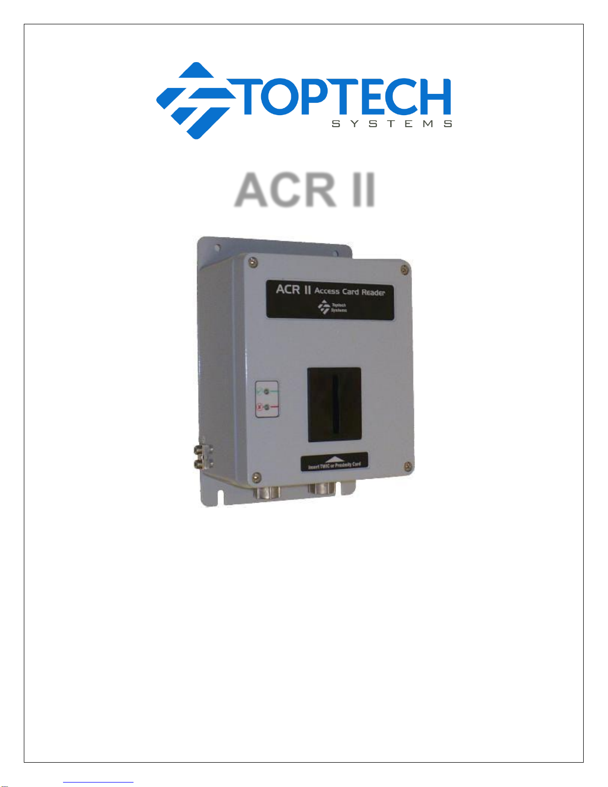
ACR II
Installation Guide
Part # 6057
July 11, 2018
Page 2

2
ACR II Installation Guide: 20180711 Part # 6057
EC Declaration Of Conformity (Valid until April 20, 2016)
the product listed below conforms to the relevant provisions of the following directives:
2004/108/EC The Electromagnetic Compatibility Directive (and its amending directives)
2006/95/EC The Low Voltage Directive (and its amending directives)
Product: Process Control Equipment
Model name/number: ACR II
Compliance with the Essential Health and Safety Requirements has been assessed by reference to the following standards:
EN 61000-6-4: 2007 Generic emissions for industrial operating environments
EN 61000-6-2: 2005 Generic immunity for industrial operating environments
EN 60950-1: 2006 Information technology equipment. Safety. General requirements
Year of CE Marking: 2010
Name: William J. Porthouse Position: Director of Engineering & Production Date: 01-August-2010
EC Declaration Of Conformity (Valid after April 20, 2016)
the product listed below conforms to the relevant provisions of the following directives:
2014/30/EU The Electromagnetic Compatibility Directive (and its amending directives)
2014/35/EU The Low Voltage Directive (and its amending directives)
Product: Process Control Equipment
Model name/number: ACR II
Compliance with the Essential Health and Safety Requirements has been assessed by reference to the following standards:
EN 61000-6-4: 2007 Generic emissions for industrial operating environments
EN 61000-6-2: 2005 Generic immunity for industrial operating environments
EN 60950-1: 2006 Information technology equipment. Safety. General requirements
Year of CE Marking: 2010
Name: William J. Porthouse Position: Director of Engineering & Production Date: 19-Apr-2016
Page 3

3
ACR II Installation Guide: 20180711 Part # 6057
ELECTRICAL CONSIDERATIONS AND REGULATORY REQUIREMENTS
This equipment is suitable for use in Class I, Division 2, Groups C and D locations.
This equipment is also suitable for use in EX Zone 2 Group IIB Locations OR non-hazardous locations.
WARNING ─ EXPLOSION HAZARD ─ SUBSTITUTION OF COMPONENTS MAY IMPAIR SUITABILITY FOR USE IN
CLASS I, DIVISION 2.
AVERTISSEMENT ─ RISQUE D’EXPLOSION ─ LA SUBSTITUTION DE COMPOSANTS PEUT RENDER CE
MATERIEL INACCEPTABLE POUR LES EMPLACEMENTS DE CLASSE I, DIVISION 2.
WARNING ─ EXPLOSION HAZARD ─ DO NOT REPLACE COMPONENTS UNLESS POWER HAS BEEN SWITCHED
OFF OR THE AREA IS KNOWN TO BE NON-HAZARDOUS.
AVERTISSEMENT ─ RISQUE D’EXPLOSION ─ COUPER LE COURANT OU S’ASSURER QUE L’EMPLACEMENT
EST DESIGNE NON DANGEREUX AVANT DE REPLACER LE COMPOSANTS.
WARNING ─ EXPLOSION HAZARD ─ DO NOT DISCONNECT EQUIPMENT UNLESS POWER HAS BEEN
SWITCHED OFF OR THE AREA IS KNOWN TO BE NON-HAZARDOUS.
AVERTISSEMENT ─ RISQUE D’EXPLOSION ─ AVANT DE DECONNECTER L’EQUIPMENT, COUPER LE COURANT
OU S’ASSURER QUE L’EMPLACEMENT EST DESIGNE NON DANGEREUX.
!!!
Page 4

4
ACR II Installation Guide: 20180711 Part # 6057
Copyright Notice
Copyright © 2006 - 2018 Toptech Systems, Inc.
The information contained in this document is proprietary and confidential. No part of this document may be copied, reproduced, or
transmitted in any medium without the express written permission of Toptech Systems, Inc.
Disclaimer
Toptech Systems assumes no responsibility for damages resulting from installation or use of its products. Toptech Systems will not be liable
for any claims of damage, lost data, or lost time as a result of using its products.
A Unit of IDEX Corporation
logo is a registered trademark of Toptech Systems, Inc.
TMS™, TMS5™, TMS6™, RCU II Remote Control Unit™, Toptech MultiLoad II™, MultiLoad II -RCU™, RCU II™, FCM Flow Control
Module™, veriFID™, ACR™, ACR II™ are trademarks of Toptech Systems, Inc.
Copyright © 2018 Toptech Systems, Inc. All Rights Reserved.
Page 5

5
ACR II Installation Guide: 20180711 Part # 6057
Table of Contents
Electrical Considerations and Regulatory Requirements .......................................................................................3
CHAPTER 1 General ...........................................................................................................................................7
1.1 Who Should Use This Guide ......................................................................................................................7
1.2 Information Alerts: .......................................................................................................................................7
1.2.1 Typographical Conventions: ...................................................................................................................7
1.2.2 Product Support ......................................................................................................................................7
1.2.3 Receiving and / or Returning Equipment: ...............................................................................................7
1.3 Operating Characteristics ...........................................................................................................................8
1.4 Electrostatic Discharge (ESD) Protection ...................................................................................................9
CHAPTER 2 Installing the ACR II ..................................................................................................................... 10
2.1 Tools Required ........................................................................................................................................ 10
2.1.1 Installation ............................................................................................................................................ 10
2.1.2 Service and Repair .............................................................................................................................. 10
2.2 Cover Closure and Bolt Replacement ..................................................................................................... 10
2.3 Mounting The ACR II Enclosure .............................................................................................................. 10
2.3.1 Drywall ................................................................................................................................................. 10
2.3.2 Wood .................................................................................................................................................... 10
2.3.3 Concrete or Cinder Block Walls ........................................................................................................... 10
2.3.4 Mounting Height Considerations ......................................................................................................... 11
2.4 Recommended Wire Sizes And Torque For All Terminal Blocks ............................................................ 12
2.5 Electrical Supply Connections ................................................................................................................. 13
2.5.1 Input Power ......................................................................................................................................... 13
2.5.2 Equipment Ground ............................................................................................................................... 16
2.5.3 Cable Entries ....................................................................................................................................... 16
CHAPTER 3 Data Communications Interface .................................................................................................. 17
3.1 Communications Protocol Selection and Connection ............................................................................. 17
3.1.1 RS-422/485 .......................................................................................................................................... 17
3.1.2 RS-232 ................................................................................................................................................. 17
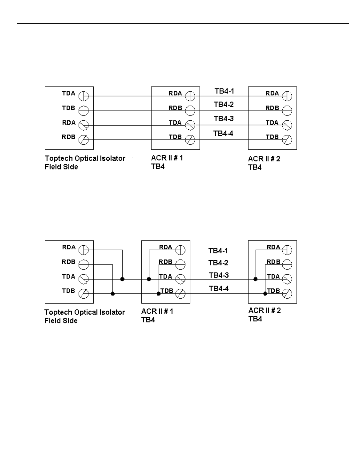
3.1.3 Host/TMS Communications (RS-485) ................................................................................................. 18
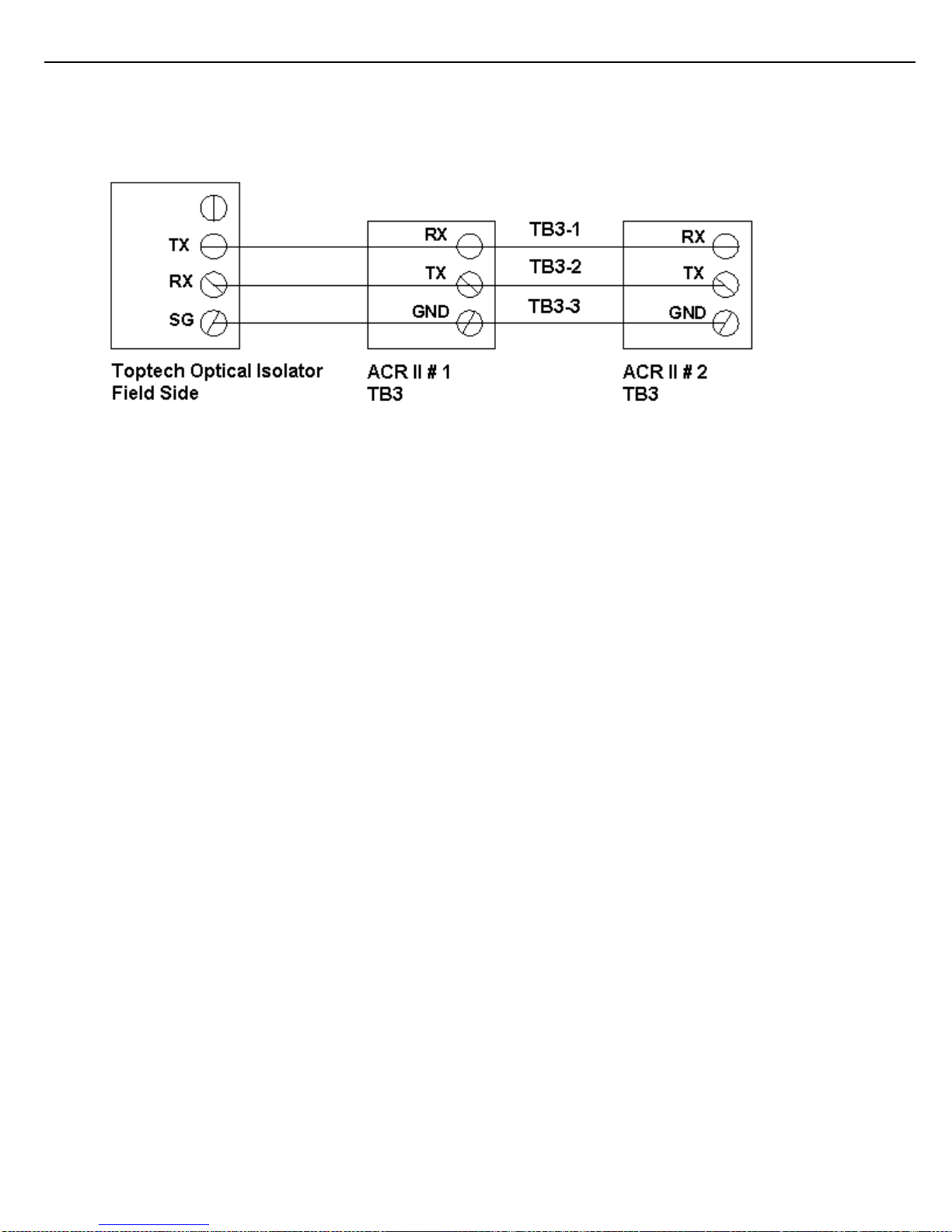
3.1.4 Host / TMS Communications (RS-232 2-wire) .................................................................................... 19
CHAPTER 4 DIGITAL I/O ................................................................................................................................. 20
4.1 digital inputs ............................................................................................................................................. 21
4.2 digital outputs ........................................................................................................................................... 21
CHAPTER 5 Configuration ............................................................................................................................... 23
5.1 Preliminary Configuration ........................................................................................................................ 23
5.2 ACR II Communication Configuration: ..................................................................................................... 24
CHAPTER 6 Service and Repair ...................................................................................................................... 26
6.1 ACR II Troubleshooting ........................................................................................................................... 26
6.2 Modular Design ........................................................................................................................................ 27
6.2.1 LED Cable Connector Removal ......................................................................................................... 28
6.2.2 ACR-FID_Combo PC Board Removal ................................................................................................. 29
6.2.3 LED PC Board Replacement ............................................................................................................... 30
6.2.4 Prox Reader Thinline II Replacement .................................................................................................. 31
6.2.5 Prox Reader RP15 Replacement ........................................................................................................ 32
6.3 TB2 Proximity Reader Connection: ......................................................................................................... 37
6.3.1 Prox Reader Thinline II: ....................................................................................................................... 37
6.3.2 Prox Reader RP15: .............................................................................................................................. 37
CHAPTER 7 Appendix ...................................................................................................................................... 38
Page 6

6
ACR II Installation Guide: 20180711 Part # 6057
Table of Figures
Figure 2.1 ACR II TERMINAL BLOCK RECOMMENDED WIRE SIZE AND SCREW TORQUE .................... 12
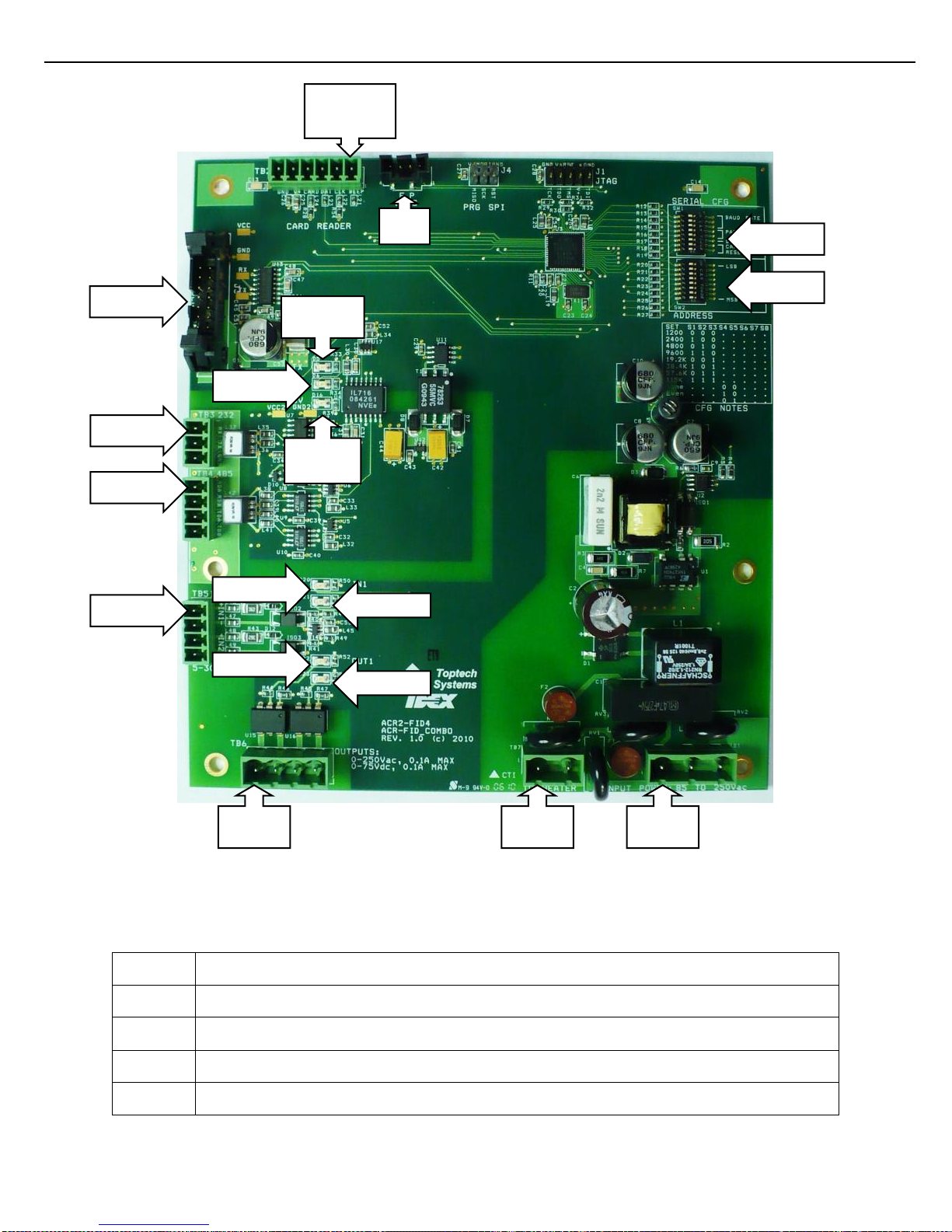
Figure 2.2 ACR-FID COMBO PC BOARD ........................................................................................................ 14
Figure 2.3 ACR-FID COMBO PC BOARD CONNECTOR AND LED IDENTIFICATION ................................. 15
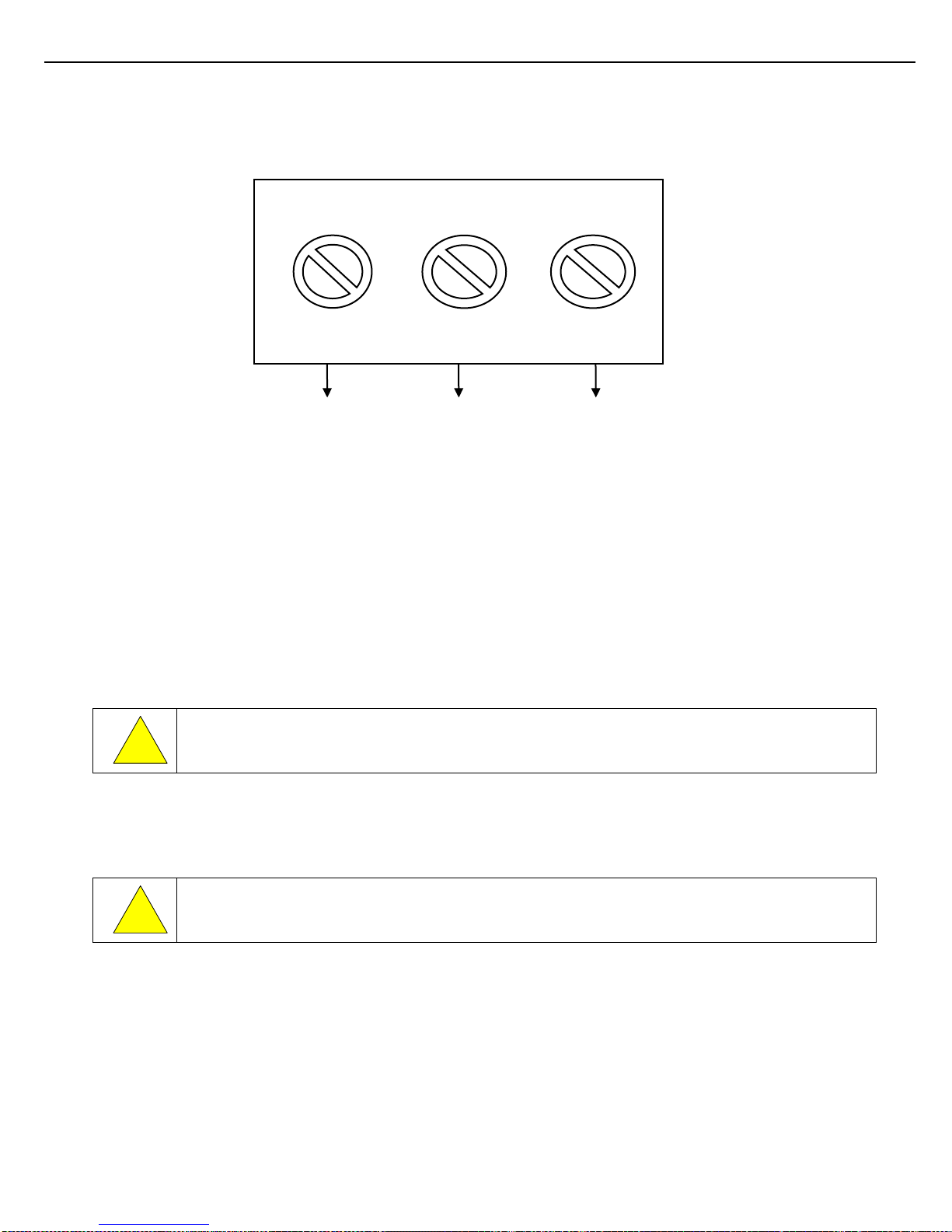
Figure 2.4 TB1 AC WIRING .............................................................................................................................. 16
Figure 3.1 4-WIRE, RS-485 CONFIGURATION ............................................................................................... 18
Figure 3.2 2-WIRE, RS-485 CONFIGURATION ............................................................................................... 18
Figure 3.3 RS-232 CONFIGURATION ............................................................................................................. 19
Figure 4.1 DIGITAL INPUT WIRING ................................................................................................................. 21
Figure 4.2 DIGITAL OUTPUT WIRING ............................................................................................................. 22
Figure 5.1 ACR-FID_COMBO SWITCH TABLES ............................................................................................ 24
Figure 5.2 ACR-FID_COMBO SW1-SW2 ......................................................................................................... 25
Figure 6.1 LED CABLE CONNECTOR ............................................................................................................. 28
Figure 6.2 LED PC BOARD .............................................................................................................................. 30
Figure 6.3 PROX READER THINLINE II .......................................................................................................... 31
Figure 6.4 HINGE RETAINING SCREW .......................................................................................................... 32
Figure 6.5 REMOVING CARD HOLDER BACK ............................................................................................... 33
Figure 6.6 PROX READER RP15 RETAINING SCREW ................................................................................. 33
Figure 6.7 BRASS INSERT ON CARD HOLDER BACK .................................................................................. 34
Figure 6.8 UNLOCK PROX READER RP15..................................................................................................... 34
Figure 6.9 PROX READER RP15 TAB CLEAR POSITION ............................................................................. 34
Figure 6.10 PROX READER RP15 REMOVED ................................................................................................. 35
Figure 6.11 PROX READER RP15 TAB AND SLOT ......................................................................................... 35
Figure 6.12 HINGE RETAINING RING CUTOUT .............................................................................................. 36
Figure 7.1 UNIT OUTLINE DRAWING – MOUNTING TEMPLATE ................................................................. 38
Figure 7.2 UNIT OUTLINE DRAWING – FRONT VIEW ................................................................................... 39
Figure 7.3 UNIT OUTLINE DRAWING – SIDE VIEW ....................................................................................... 40
Figure 7.4 UNIT OUTLINE DRAWING – BOTTOM VIEW ................................................................................ 41
Figure 7.5 PROX READER RP15 TAB – TOP LEVEL VIEW........................................................................... 42
Figure 7.6 PROX READER RP15 TAB – EXPLODED VIEW........................................................................... 43
Figure 7.7 PROX READER THINLINE II – TOP LEVEL VIEW ........................................................................ 44
Figure 7.8 PROX READER THINLINE II EXPLODED VIEW ........................................................................... 45
Figure 7.9 COVER – EXPLODED VIEW .......................................................................................................... 46
Figure 7.10 PARTS LIST .................................................................................................................................... 47
Figure 7.11 ACR II INSIDE VIEW ....................................................................................................................... 48
Figure 7.12 RP15 - STATUS LIGHT ................................................................................................................... 49
Figure 7.13 Thinline - STATUS LIGHT ............................................................................................................... 49
Page 7
Chapter 1 – General
7
ACR II Installation Guide: 20180711 Part # 6057
!
CHAPTER 1 GENERAL
1.1 WHO SHOULD USE THIS GUIDE
This guide is intended for individuals installing veriFID II equipment, engineering firms developing site electrical
drawings, and users troubleshooting system operation such as managers, system administrators, technicians, and
meter proving personnel.
1.2 INFORMATION ALERTS:
Important information to enhance understanding and make better use of the product.
Indicates potential damage to hardware or loss of data.
Potential for property damage or that personal injury may occur. Pay close attention and follow
instructions when you see this symbol.
1.2.1 TYPOGRAPHICAL CONVENTIONS:
Boldface: Indicates what you are to press on the keypad. Example: Key in 00000.
Italics: Emphasizes a key product or industry term.
Example: the display features a pick list style of item selection.
1.2.2 PRODUCT SUPPORT
Thank you for your purchase of this Toptech product. Should you require information or technical assistance
beyond that provided in this manual, please call Toptech’s Technical Assistance Center at 407-332-1774 x381.
You may also reach us online 24x7 at http://www.toptech.com/support. Additionally, you can email any issues you
have with our hardware to [email protected]. Information or technical assistance provided by the
Toptech Assistance Center may result in incidental charges on a time and materials basis.
1.2.3 RECEIVING AND / OR RETURNING EQUIPMENT:
The veriFID II should be immediately inspected after opening the packaging case. If any damage is visible notify
the carrier at once to establish liability. Contact Toptech Account Management to initiate timely repair or
replacement of the unit.
Account Management will issue a Return Materials Authorization (RMA) to return the product or parts requiring
repair. Do not return any material to Toptech without an RMA.
Account Management contact information: Account Management, Toptech Systems, 1124 Florida Central Pkwy,
Longwood, FL. Telephone: (407) 332-1774.
Prior to installation the veriFID II should be stored in its packing case and be protected from damage due to handling
and adverse weather conditions.
Page 8

Chapter 1 – General
8
ACR II Installation Guide: 20180711 Part # 6057
1.3 OPERATING CHARACTERISTICS
For product outline and dimensions see Appendix Figures 6.1 to 6.4.
Operating voltage: 85 - 250 Vac, 47-63 Hz
Operating current: 100mA
Operating temperature: -40°F to 140°F (-40°C to 60°C)
Enclosure: Type 4, IP65
Weight: 10 lbs (4.6 kg)
Card reader :(Two options)
Card Reader Thinline II (Two options captive or non captive, Factory set) HID OEM
Card Reader RP15 (Two options captive or non captive, Factory set) HID OEM
Communications:
1 serial port: RS-232 OR RS-485
I/O:
Two Digital Inputs: 5-30Vdc
Two Digital Outputs: 0-250Vac, 0.1A MAX / 0-75Vdc, 0.1A MAX
Page 9

Chapter 1 – General
9
ACR II Installation Guide: 20180711 Part # 6057
1.4 ELECTROSTATIC DISCHARGE (ESD) PROTECTION
The ACR II contains electronic components and assemblies subject to damage by ESD. The ACR II was designed
to protect against ESD while the unit is closed and in normal operation. Proper handling procedures must be
observed during the removal, installation, repair and other handling of printed circuit board assemblies, electronic
devices and components to include:
1) Service to be performed by authorized personnel only.
2) The person performing the service must be grounded by an ESD grounding strap.
3) While performing maintenance or repair, touch an unpainted metal of the ACR II surface prior to
touching or handling any printed circuit boards or electronic components.
4) Printed circuit board assemblies must be placed in and transported in conductive bags or other
conductive containers.
5) Printed circuit boards must not be removed from the conductive container until time of use.
6) All other “best” practices for protecting devices from ESD must be observed.
Page 10

Chapter 2 – Installing the ACR II
10
ACR II Installation Guide: 20180711 Part # 6057
CHAPTER 2 INSTALLING THE ACR II
2.1 TOOLS REQUIRED
2.1.1 INSTALLATION
- ¼” Flat Head screw driver is required for tightening cover screws
2.1.2 SERVICE AND REPAIR
- #2 Philips screw driver for circuit board removal
- #2 Philips screw driver for card reader removal
- ¼ Flat Head screw driver for hinge removal
- 5/16 Nut driver to remove LED PCB and PROX bracket stainless steal.
2.2 COVER CLOSURE AND BOLT REPLACEMENT
When closing the cover gently lift on the bottom of the cover when in position for starting one or two of the right
corner screws. This is done to assist in alignment of the cover and base holes for starting the screws. The enclosure
cover is secured to the housing by four 6mm slotted/Philips screws. When the screws are removed, the front cover
will swing left and hang from its hinges. The screws are captive and will remain with the cover.
2.3 MOUNTING THE ACR II ENCLOSURE
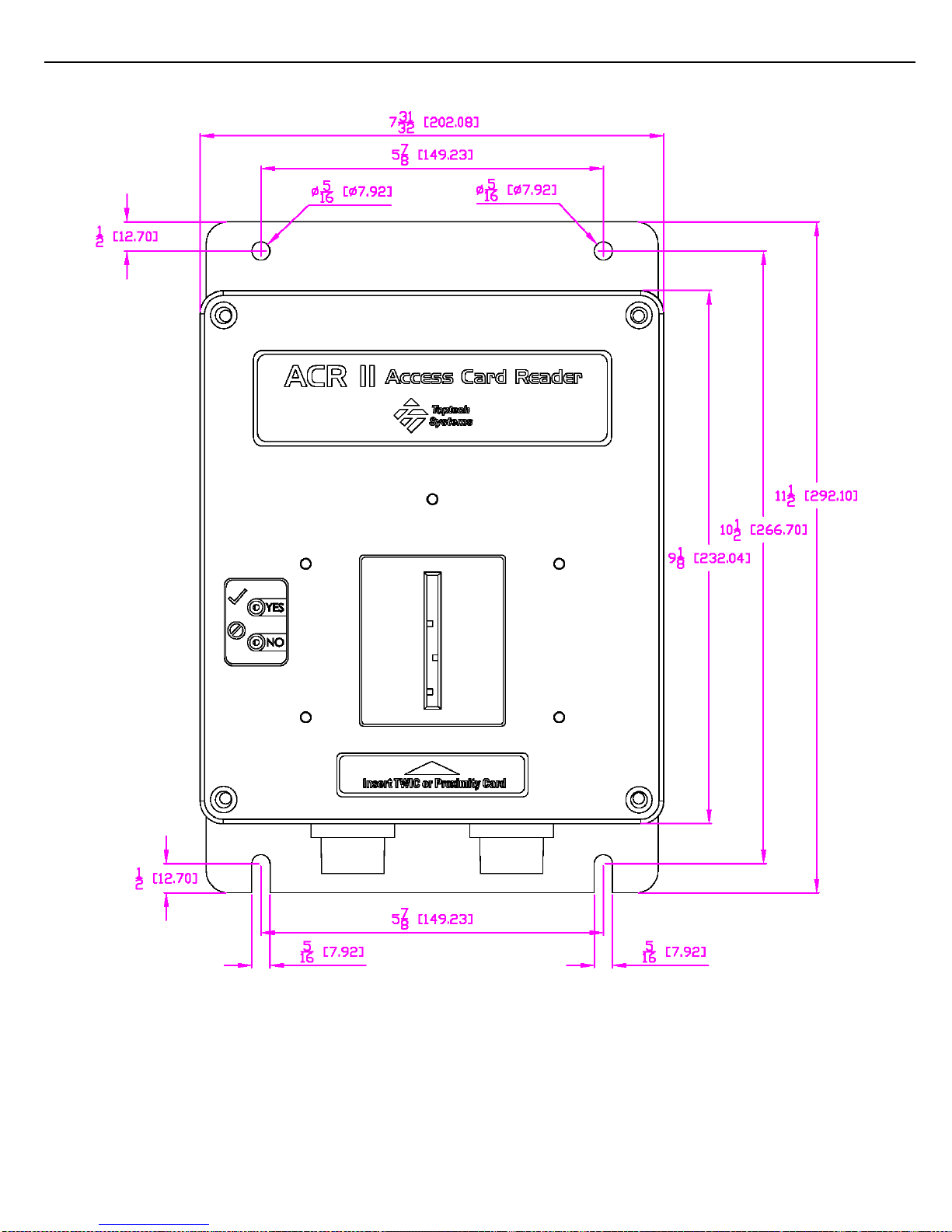
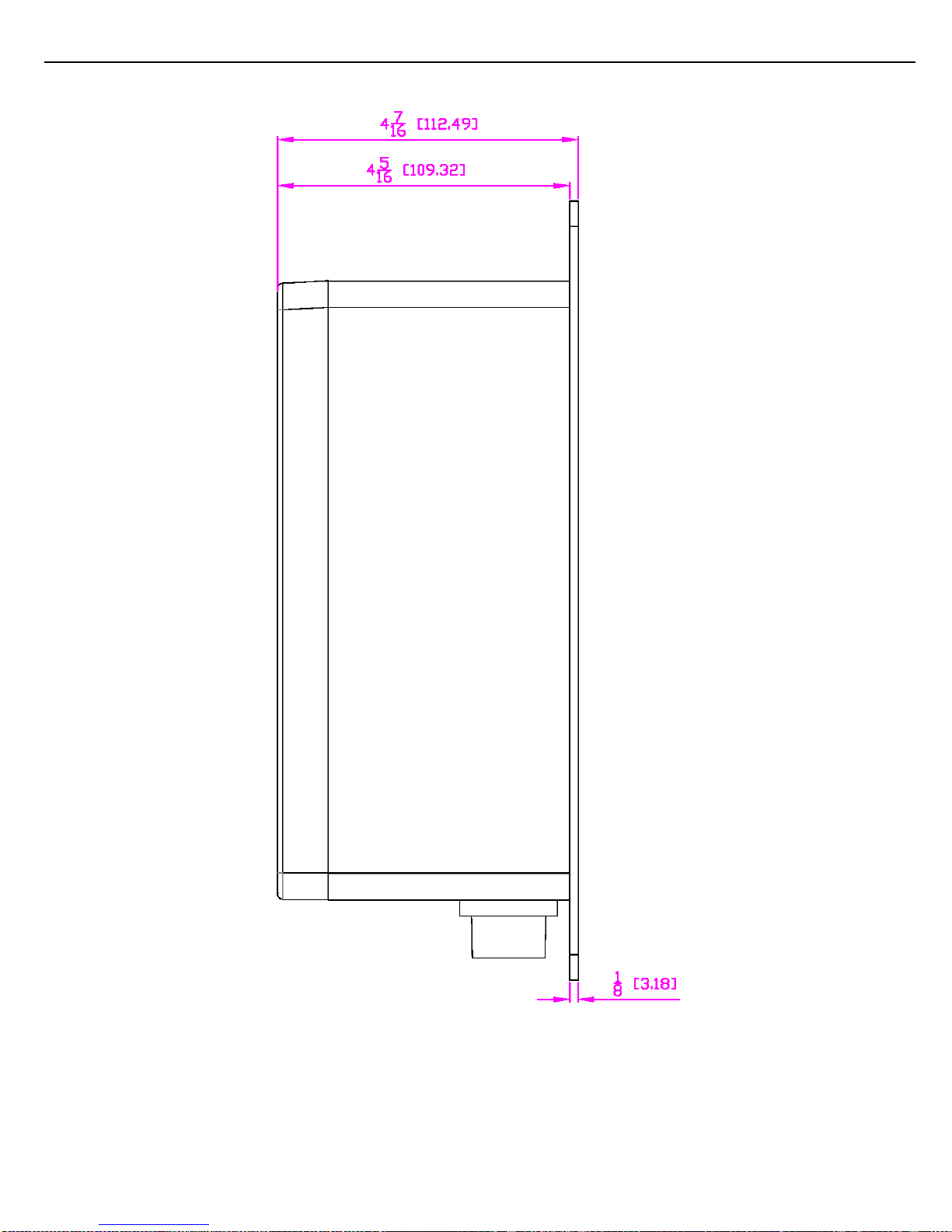
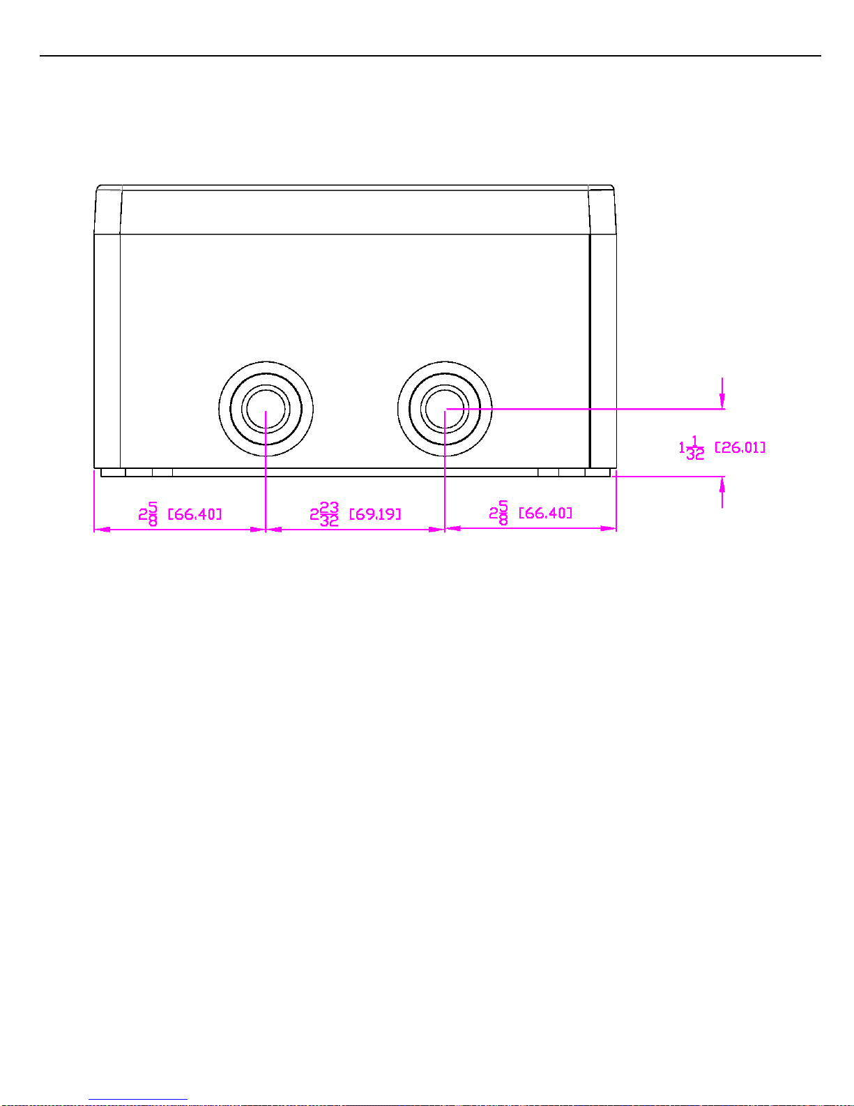
Exterior dimensions of the standard ACR II enclosure are shown in the Appendix, see figures 7.2-7.4. There is only
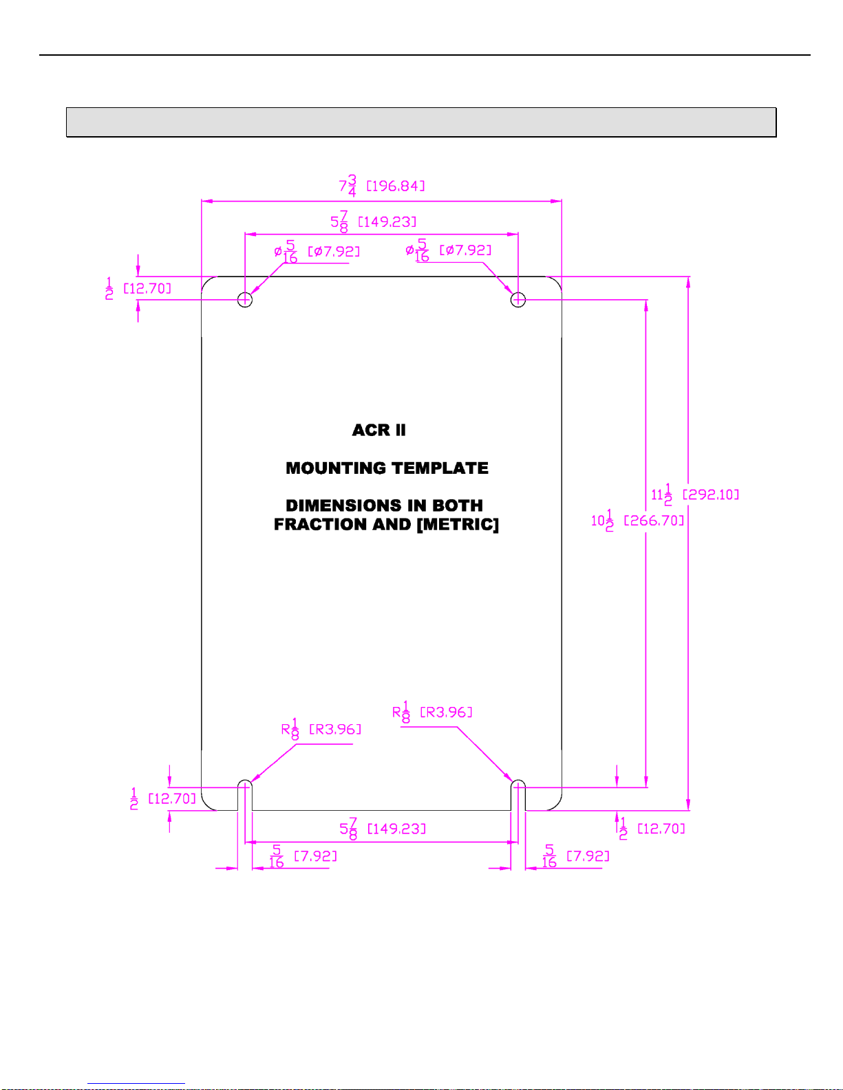
one mounting orientation possible reference figure 7.1 for ACR II Mounting Template. The cable entries are located
at the bottom of the unit.
Appropriate fasteners must be selected to support the minimum weight of 10 lbs (4.6 kg). Toptech offers the
following mounting suggestions for three typical surfaces: drywall, wood or concrete/cinder block.
2.3.1 DRYWALL
Insert four fasteners through the corner mounting holes, shown in Figure 7.2. For the fasteners, use #12 x 1” (M5
x 25 mm) Phillips pan head sheet metal screws inserted in #12 (M5) self-tapping nylon anchors.
Place one #12, 3/8” OD (M5, 10 mm 0D) flat washer under the head of the screw before inserting the screw into
the mounting hole.
2.3.2 WOOD
Follow the instructions above for Drywall installation, but substitute #12 x 1” (M5 x 25 mm) wood screws for the four
sheet metal screws. Do not use the self-tapping nylon inserts.
2.3.3 CONCRETE OR CINDER BLOCK WALLS
Follow the instructions above for Drywall installation, but substitute a 1/4 ” x1 1/4” Tapcon masonry fastener for the
four sheet metal screws. Do not use the self-tapping nylon inserts.
Drill pilot holes for the Tapcons using a 3/16” x 3 ½” masonry drill bit.
Page 11

Chapter 2 – Installing the ACR II
11
ACR II Installation Guide: 20180711 Part # 6057
2.3.4 MOUNTING HEIGHT CONSIDERATIONS
The following factors should be taken into consideration when deciding where to mount the ACR II
control Unit.
The ACR II unit should be positioned for convenient access to the front panel and mounted in a
vertical, upright position. Try to mount the unit approximately five feet above the floor so that
the card reader can be accessed from a comfortable position.
The ACR II is housed in a Type4, IP65 enclosure. It should never be submersed in liquid.
Page 12
Chapter 2 – Installing the ACR II
12
ACR II Installation Guide: 20180711 Part # 6057
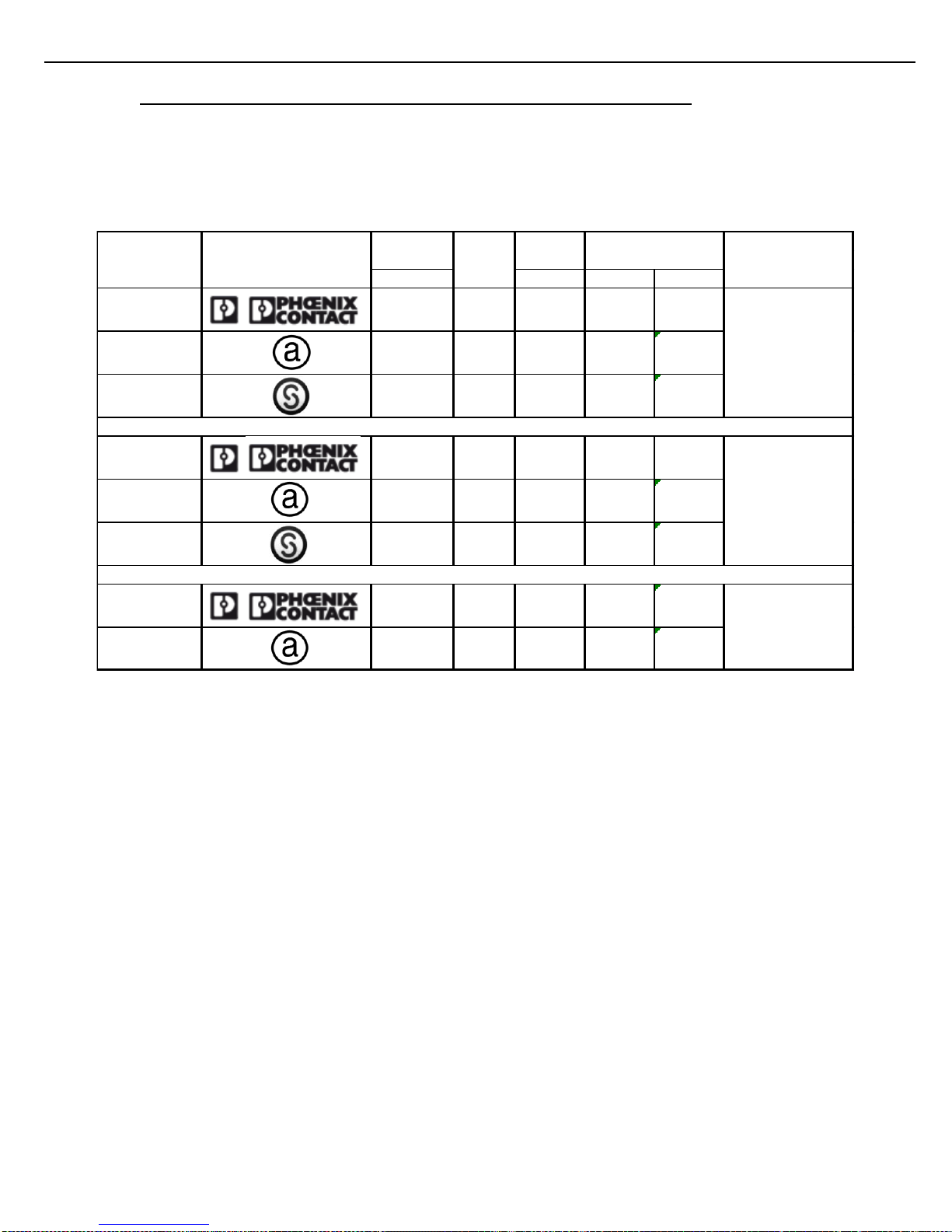
2.4 RECOMMENDED WIRE SIZES AND TORQUE FOR ALL TERMINAL BLOCKS
Three sizes of terminal blocks are used in the veriFID II product: 7.62 mm pitch (supply power), 5.08 mm pitch (line
voltage switching), and 3.81 mm pitch (serial communication, or dc voltages). All sizes, orientations, and
manufacturer brands have different torque and wire size specifications. Please follow the recommendations in
Figure 2.1 below. The manufacturer may be determined by looking for the logo molded into the terminal block,
usually on the side.
Figure 2.1 ACR II TERMINAL BLOCK RECOMMENDED WIRE SIZE AND SCREW TORQUE
[mm] [AWG] [Nm] [LB in]
Phoenix 7.62 Straight 30 - 12 .6 - .8 5 - 7
On-Shore
Technology
7.62 Straight 24 - 12 0.40 3.5
Sauro 7.62 Straight 30 - 12 0.8 7
Phoenix 5.08 Straight 30 - 12 .6 - .8 5 - 7
On-Shore
Technology
5.08 Straight 24 - 12 0.40 3.5
Sauro 5.08 Straight 30 - 12 0.8 7
Phoenix 3.81 Straight 30 - 14 0.5 4
On-Shore
Technology
3.81 Straight 28 - 16 0.19 1.7
TB1
TB6
Terminal
Block Pitch
Allowable
Wire Size
TB3-TB5
Manufacturer
Orienta-
tion
Logo
Recommended
Screw Torque
Location
Page 13
Chapter 2 – Installing the ACR II
13
ACR II Installation Guide: 20180711 Part # 6057
!
2.5 ELECTRICAL SUPPLY CONNECTIONS
The ACR II is equipped for 85 -250Vac operation.
Use field wiring rated 75ºC or greater.
Do not route AC and DC wiring in the same conduit.
All wiring must enter the ACR II enclosure through conduit via entries in the bottom of the enclosure. All conduits
must be terminated at the enclosure by use of appropriately rated conduit hubs or glands.
Wires must be stripped ¼” and fully inserted into terminal block with no bare conductor exposed. See section 2.4
for recommended wire size and torque values.
The unit requires a safety ground connection as described in section 2.5.2 below.
A service loop is recommended for all wires and cables entering the enclosure.
Do not allow service loop cables to overlap the circuit boards. Coil any cable length in the
bottom of the enclosure. Keep AC wiring separated from all other wiring in the enclosure.
Wiring must comply with all local electrical codes.
2.5.1 INPUT POWER
Provide over current protection using a 15 Amp circuit breaker or equivalent. The breaker also serves as a means
of disconnection from the operating supply as required by UL/ISA/IEC 60950-1 and CAN/CSA-C22.2 NO. 60950-
1.The disconnect device may not be blocked or be made difficult to operate by the ACR II or any other device. Note
that installation of disconnects are typically prohibited in Class I, Division 2 locations.
Power required: 85 – 250 Vac, 47 – 63 Hz. The power connector (TB1) is located in the right hand corner of the
ACR-FID_COMBO board as shown in figure 2.2. Select supply wire rated 300V or better with a flammability rating
of at least VW-1. See figure 2.3 for wiring guide for TB1.
Page 14
Chapter 2 – Installing the ACR II
14
ACR II Installation Guide: 20180711 Part # 6057
Figure 2.2 ACR-FID COMBO PC BOARD
TB1
AC INPUT, pin 1 Line, pin 2 Neutral and pin 3 Ground.
TB2
CARD READER
TB3
232 COM, pin1 RX, pin 2 TX and pin 3 GND.
TB4
485 COM, pin 1 RDA, pin 2 RDB, pin 3 TDA and pin 4 TDB.
TB5
DIGITAL INPUTS (5-30Vdc), pin1 IN1 +, pin 2 IN1 -, pin 3 IN2 +, and pin 4 IN2 -.
TB3 PIN 1
SW1
SW2
TB6 PIN 1
TB2 PIN 1
5V LED
TX LED
J3
RX LED
J2
TB4 PIN 1
TB5 PIN 1
TB7 PIN 1
TB1 PIN 1
Page 15

Chapter 2 – Installing the ACR II
15
ACR II Installation Guide: 20180711 Part # 6057
Figure 2.3 ACR-FID COMBO PC BOARD CONNECTOR AND LED IDENTIFICATION
TB6
SWITCHED OUTPUTS (0-250Vac, 0.1A MAX / 0-75Vdc, 0.1A MAX), pin1 OUT1 +Vdc or AC Line, pin2 OUT1 Vdc or AC Neutral, pin 3 OUT2 +Vdc or AC Line, pin 4 OUT2 –Vdc or AC Neutral.
TB7
AC POWER OUT TO HEATER (NOT USED IN ACR II)
J2
LEDS (FRONT PANEL LED INDICATORS)
J3
VeriFID SENSOR CABLE (NOT USED IN ACR II)
SW1
BAUD RATE (S1-3), PARITY (S4-5), DIAG-ON (S6) (COM TEST SIGNAL), CAPTIVE- ON (S7) (NOT USED IN
VerFID MODE), OPEN PROTOCOL ENABLE (S8)
SW2
ADDRESS (S1 LSB) (S8 MSB)
TX LED
TURNS ON DURING COM TRANSMITION (GREEN)
RX LED
TURNS ON DURING COM RECEIVING (YELLOW)
5V LED
ON INDICATES COM IS POWERED UP (RED)
IN1 LED
This LED will turn on (GREEN) when IN1 (TB5 pin 1(+) and pin 2(-)) has 5-30Vdc applied to it.
IN2 LED
This LED will turn on (GREEN) when IN2 (TB5 pin 3(+) and pin 4(-)) has 5-30Vdc applied to it.
OUT 1 LED
This LED will turn on (GREEN) when OUT 1 (TB6 pin 1 and 2) is turned on.
OUT 2 LED
This LED will turn on (GREEN) when OUT 2 (TB6 pin 3 and 4) is turned on.
Page 16
Chapter 2 – Installing the ACR II
16
ACR II Installation Guide: 20180711 Part # 6057
!
!
Figure 2.4 TB1 AC WIRING
2.5.2 EQUIPMENT GROUND
A safety ground should be attached to terminal block TB1 to maintain electrical safety in the event of a fault
condition. Follow the terminal block wiring instructions in section 2.5.1, and see figure 2.4.
Note that the external ground connection is not provided for the attachment of the protective conductor (the safety
ground). Rather, it is provided only as a supplemental bonding connection where local authorities permit or require
such a connection, for example, as a means of equipotentiality. The wire connection is on the bottom right side
exterior surface. The following wire sizes may be used: 10 AWG (5.26 mm2) or 11 AWG (4.17 mm2).
Do not connect the power supply dc common to earth ground.
2.5.3 CABLE ENTRIES
Two 1/2” NPT conduit hubs are provided for the installation of conduit and cables.
WARNING: If there are unused holes, blanking elements appropriate for the type enclosure must
be used.
L
2
1
G
N
3
TB1
Ground
Line
Neutral
Page 17

Chapter 3 – Data Communications Interface
17
ACR II Installation Guide: 20180711 Part # 6057
CHAPTER 3 DATA COMMUNICATIONS INTERFACE
The ACR II has one serial communication port (see Figure 2.2). This allows for communication with a Host device
(such as TMS) with a choice of either 232 or 485.
3.1 COMMUNICATIONS PROTOCOL SELECTION AND CONNECTION
3.1.1 RS-422/485
RS-422/485 communications protocol is designed for multi-point (i.e. computer to multiple devices, also called multidropped) communications up to 4,000 feet (1,220 Meters).
RS-422 requires 4-wires (2 twisted pair) for full duplex communications and utilizes a transmit pair of wires (TDA &
TDB) and a receive pair of wires (RDA & RDB).
RS-485 requires 2-wires (1 twisted pair) for half duplex communications and utilizes a single pair of wires (TDA/RDA
& TDB/RDB) for transmit and receive.
This manual will typically refer to both RS-422 and RS-485 as simply RS485 2 wire or RS485 4 wire.
A ground wire is not required, though some devices may have a terminal block for a ground.
Wire used must meet the following characteristics:
24 AWG stranded.
4-wire, two twisted pair with overall shield.
2-wire, one twisted pair with overall shield.
30 pF maximum between conductors.
1,000 ohm impedance.
Maximum length: 4,000 feet (1,220 Meters)
Maximum stub length: 15 feet.
All exposed shields must be properly insulated to prevent short circuits.
All shields must be continuous, soldered, and properly insulated.
3.1.2 RS-232
RS-232 protocol is designed for point-to-point (i.e., computer to a single device) communications limited to 50 feet
requiring a minimum of 3 wires – transmit, receive and ground. Additional wires are required for hardware
handshaking when using printers and data loggers.
Wire used must meet the following characteristics:
24 AWG.
3 conductor with overall shield (data only) or 8 conductor with overall shield (full handshaking).
30 pF maximum between conductors.
If a service loop is used, the maximum wire length in the service loop should not exceed 3 inches
[75mm].
Separate AC and DC wiring by at least 3 inches [75mm]. Do not allow excess wire in the service
loop to overhang printed circuit board.
Page 18
Chapter 3 – Data Communications Interface
18
ACR II Installation Guide: 20180711 Part # 6057
3.1.3 HOST/TMS COMMUNICATIONS (RS-485)
Figure 3.1 4-WIRE, RS-485 CONFIGURATION
Figure 3.2 2-WIRE, RS-485 CONFIGURATION
Page 19
Chapter 3 – Data Communications Interface
19
ACR II Installation Guide: 20180711 Part # 6057
3.1.4 HOST / TMS COMMUNICATIONS (RS-232 2-WIRE)
Figure 3.3 RS-232 CONFIGURATION
Page 20

Chapter 4 – Digital I/O
20
ACR II Installation Guide: 20180711 Part # 6057
CHAPTER 4 DIGITAL I/O
The ACR II has two digital inputs and two digital outputs. All input and output circuits are totally independent from
each other with no shared common.
If a service loop is used, the maximum wire length in the service loop should not exceed 3 inches
[75mm].
Separate AC and DC wiring by at least 3 inches [75mm]. Do not allow excess wire in the service
loop to overhang printed circuit board.
Page 21
Chapter 4 – Digital I/O
21
ACR II Installation Guide: 20180711 Part # 6057
4.1 DIGITAL INPUTS
Voltage: 5-30VDC
Nominal Current (DRAW): 6mA @24VDC, 3mA @12VDC
Frequency: 1-5,000Hz
Inputs are electrically isolated from the device by 3750V.
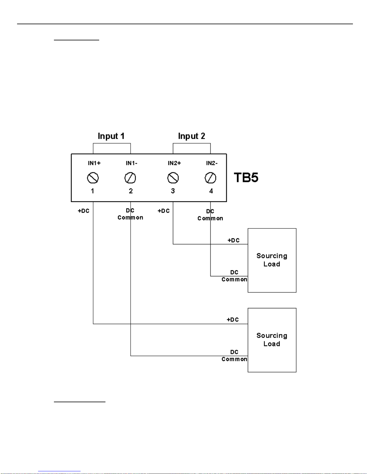
TB2.1 Input #1 +
TB2.2 Input #1 –
TB2.3 Input # 2+
TB2.4 Input #2 –
The source voltage for the DC inputs must be provided by an external source.
Figure 4.1 DIGITAL INPUT WIRING
4.2 DIGITAL OUTPUTS
Voltage: 0 - 250VAC, 0 - +/-75VDC
Max Current: 100mA.
Outputs are electrically isolated from the device by 3750V.
Page 22
Chapter 4 – Digital I/O
22
ACR II Installation Guide: 20180711 Part # 6057
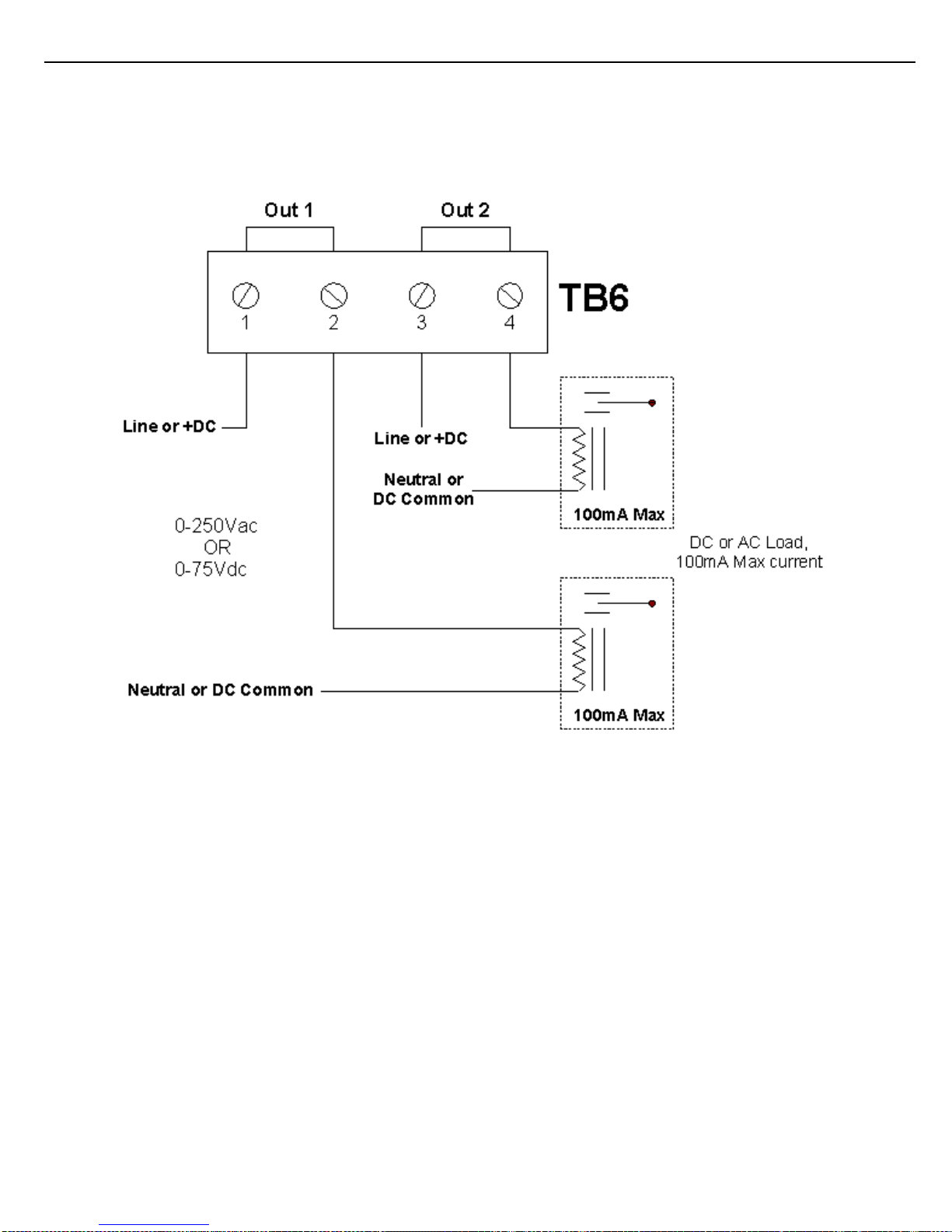
TB3.1 Closure connection for Output #1
TB3.2 Closure connection for Output #1
TB3.3 Closure connection for Output #2
TB3.4 Closure connection for Output #2
Figure 4.2 DIGITAL OUTPUT WIRING
Page 23
Chapter 5 – Configuration
23
ACR II Installation Guide: 20180711 Part # 6057
CHAPTER 5 CONFIGURATION
5.1 PRELIMINARY CONFIGURATION
The ACR II will be required to be used in conjunction with TMS system.
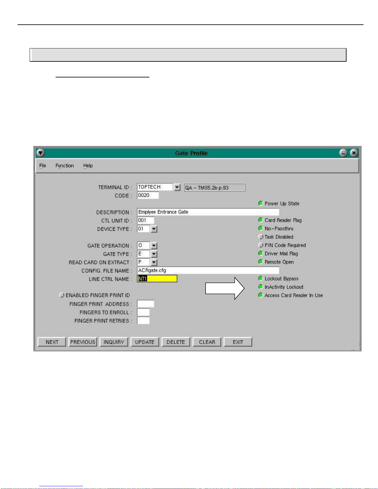
To associate an ACR with an entrance Gate at a terminal running TMS5, select the specific Gate
Profile from the TMS Main Menu, as follows:
From the TMS Main Menu select Facility | Facility Configuration Menu | Gate Profile.
The Gate Profile screen displays.
Enter the Gate code for the gate in question.
Then, click On the “Access Card Reader In Use” button.
Click On
Page 24
Chapter 5 – Configuration
24
ACR II Installation Guide: 20180711 Part # 6057
5.2 ACR II COMMUNICATION CONFIGURATION:
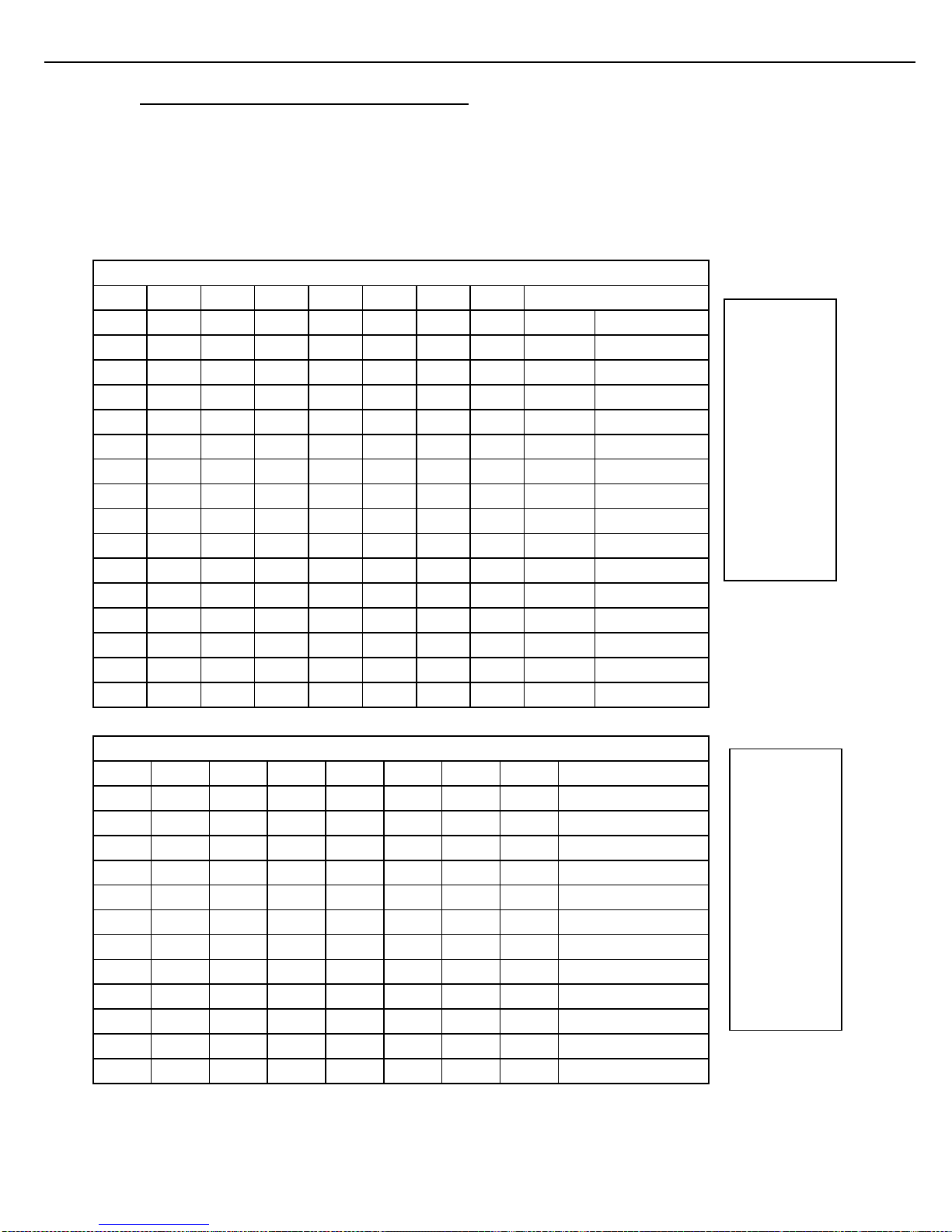
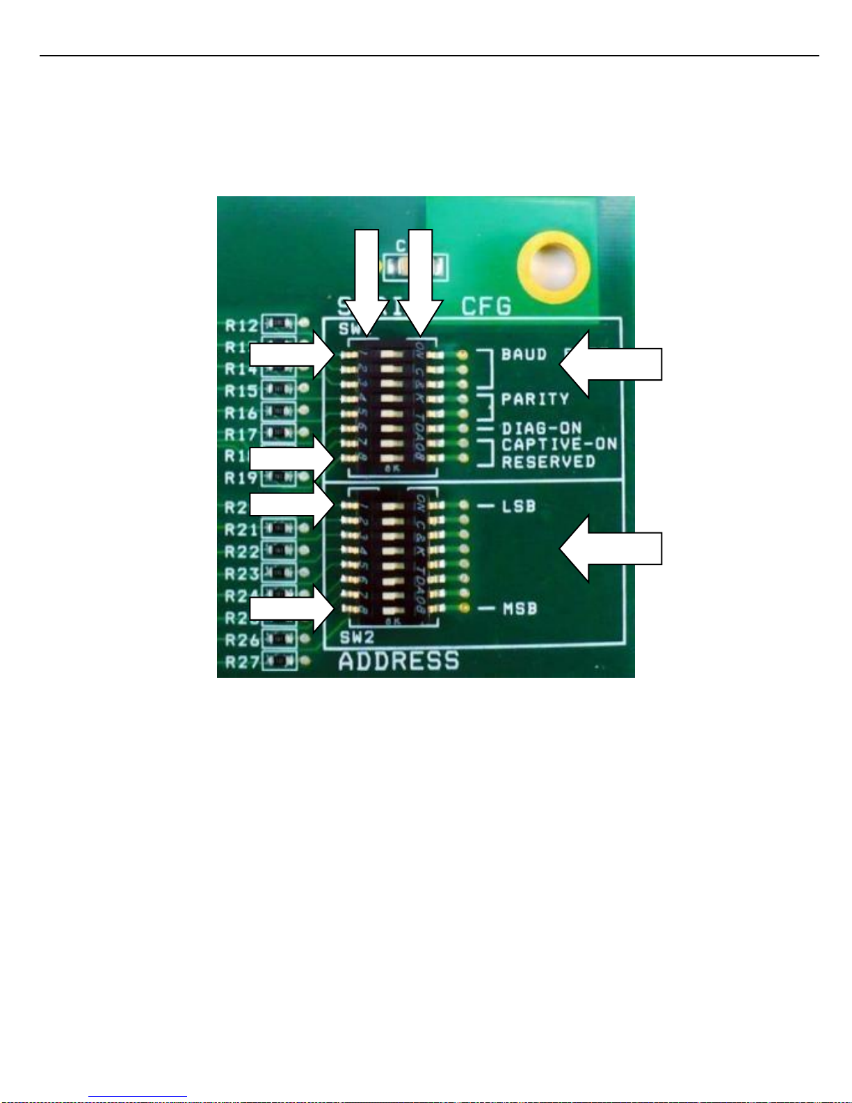
Configuring the communication parameters of the ACR II is accomplished by setting the DIP switches SW1 and
SW2 (see Fig 4.2). The switches are located on the upper right corner of the PC board (see Figure 2.2).
The switches are used to configure ACR II baud rate, parity address, captive or non captive, and the
communication protocol (open protocol vs proprietary protocol). Baud rate and parity are set using the first five
switches of SW1. Address is set using the eight switches on SW2.
Note: if using a TMS6 system, S8 should be set to OFF. Otherwise S8 should be turned ON to enable open protocol.
Configuration Switches SW1
S1
S2
S3
S4
S5
S6
S7
S8
SETTING
off
off
off 1200
baud
on
off
off 2400
baud
off
on
off 4800
baud
on
on
off 9600
baud
off
off
on 19.2K
baud
on
off
on 38.4K
baud
off
on
on 57.6K
baud
on
on
on 115.2K
baud
off
off no
parity
on
off even
parity
off
on odd
parity
off
TEST
Diagnostic- On
off ACR
Captive-On
off Open Protocol
Configuration Switches SW2
S1
S2
S3
S4
S5
S6
S7
S8
ADDRESS
off
off
off
off
off
off
off
off
000
on
off
off
off
off
off
off
off
001
off
on
off
off
off
off
off
off
002
on
on
off
off
off
off
off
off
003
off
off
on
off
off
off
off
off
004
on
off
on
off
off
off
off
off
005
off
on
on
off
off
off
off
off
006
on
on
on
off
off
off
off
off
007
… on
off
on
on
on
on
on
on
253
off
on
on
on
on
on
on
on
254
on
on
on
on
on
on
on
on
255
Figure 5.1 ACR-FID_COMBO SWITCH TABLES
Off S1 On
Off S2 On
Off S3 On
Off S4 On
Off S5 On
Off S6 On
Off S7 On
Off S8 On
Off S1 On
Off S2 On
Off S3 On
Off S4 On
Off S5 On
Off S6 On
Off S7 On
Off S8 On
Page 25
Chapter 5 – Configuration
25
ACR II Installation Guide: 20180711 Part # 6057
Figure 5.2 ACR-FID_COMBO SW1-SW2
S1
O
F
F
S8
S1
S8
SW1
O
N
SW2
Page 26
Chapter 6 – Service and Repair
26
ACR II Installation Guide: 20180711 Part # 6057
!
CHAPTER 6 SERVICE AND REPAIR
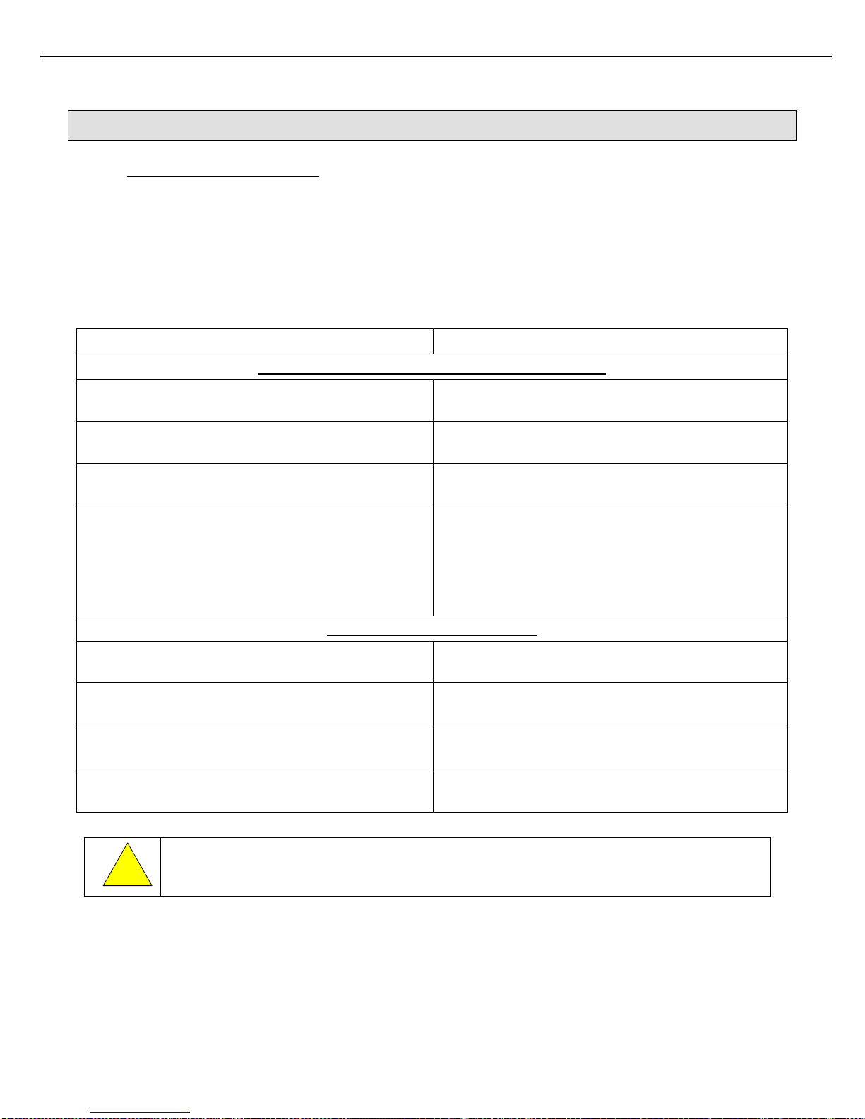
6.1 ACR II TROUBLESHOOTING
The following are suggestions for basic ACR II troubleshooting by qualified ACR II customers. If problems cannot
be resolved within a reasonable time frame using these methods, please contact your Toptech Account Manager,
who will facilitate resolution in a timely manner.
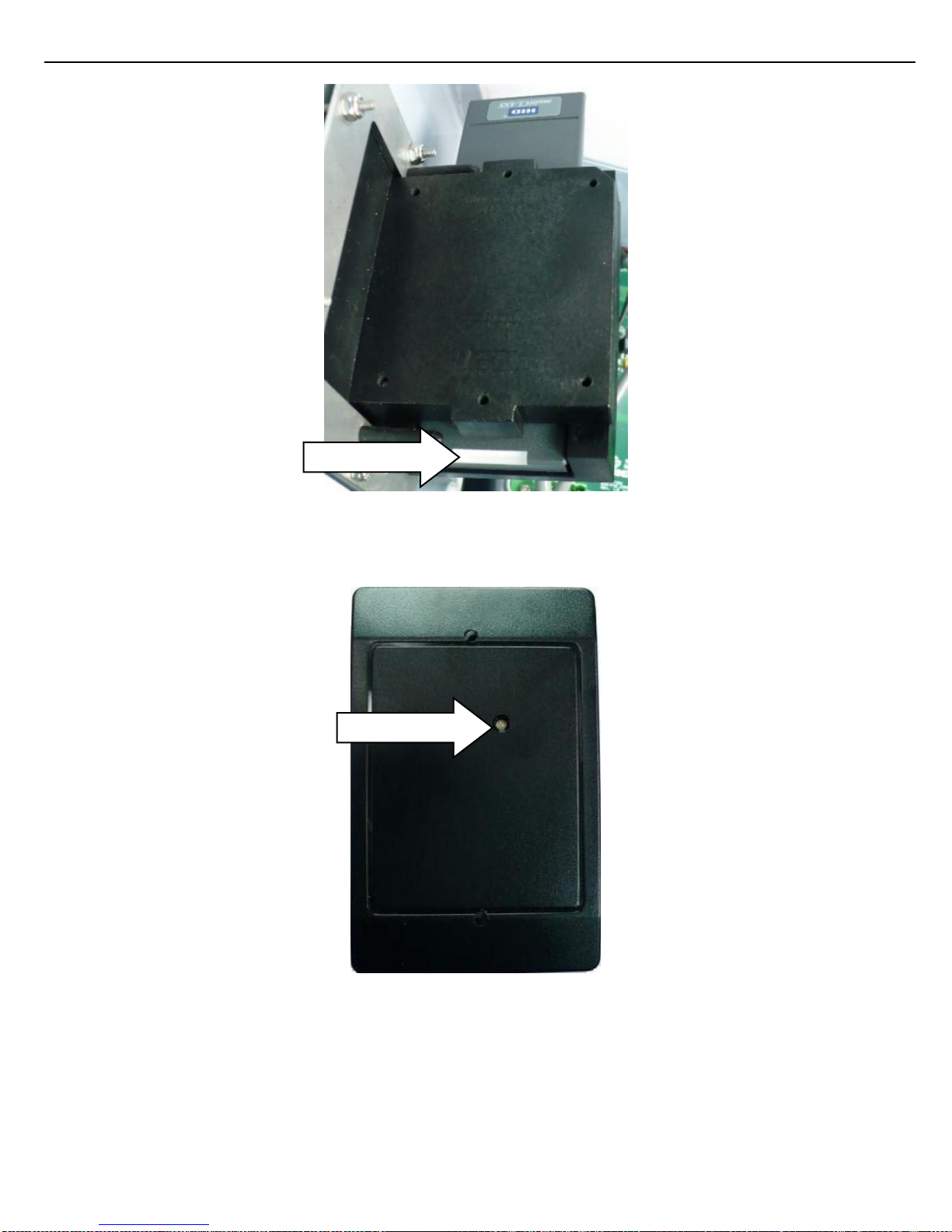
Note: Refer to figure 2.2 ACR-FID_COMBO board for LED locations for 5V, RX and TX LED. To view status light
on Prox reader the ACR II cover will need to be opened. The status light on an RP15 is found on the bottom of the
reader (refer to figure 7.12). On a Thinline II reader the card reader will need to be dismounted from the Card Holder
to view the status light on the front of reader (refer to figure 7.13).
Symptom/Condition
Possible Solution/Fix
ACR-FID COMBO board and Communication Problems
If the 5V LED on the ACR-FID_COMBO board is not
illuminated…
Verify the mains power is good.
If the RX LED on the ACR-FID_COMBO board does
not flash when COM commands are sent…
Verify the RDA/RDB or RX/GND serial connections
and polarity back to the host.
If the TX LED on the ACR-FID_COMBO board does not
flash when COM commands are sent…
Verify COM settings and address on the ACRFID_COMBO dip switches.
If no communication is received back at the host when
COM commands are sent…
Verify the TDA/TDB or RX/GND serial connections and
polarity back to the host.
As an additional diagnostic tool, enable the ACR’s Com
Diagnostic Mode by setting the S2 Dip #6 On. When
enabled, an identification string will be transmitted once
per second back to the host. (See Warning below.)
Card Reader Operation Problems
If the card reader does not flash green when a card is
swiped…
Try again with a different card.
If the card reader status light flashes green when the
card is swiped, but neither YES nor NO lights turn on…
Verify that the TMS gate in question is enabled and
running.
If the card reader status light flashes green when the
card is swiped and the NO light turns on…
Verify that the card is valid in the host database.
If the YES lights, but access is not granted…
Verify the TMS gate or Opto configuration, and verify
ACR relay connections and specifications.
Because of the possibility of message collisions, Com Diagnostic Mode should not be used
during normal operation.
Page 27

Chapter 6 – Service and Repair
27
ACR II Installation Guide: 20180711 Part # 6057
!!!
6.2 MODULAR DESIGN
The ACR II has been constructed with replaceable modules or sub-assemblies that are available from Toptech (see
Figure 7.5-10 for part numbers). These include:
ACR-FID_COMBO PC board
LED PCB board
Prox Card Reader
The following sections describe how to remove and replace each subassembly and where possible, how to further
disassemble the subassembly
NOTE: Do not service ACR II without removing mains power.
NOTE: Do not open the ACR II enclosure while the ACR II is energized.
NOTE: Do not service ACR II without removing the external power supplying the Digital I/O ports.
Page 28
Chapter 6 – Service and Repair
28
ACR II Installation Guide: 20180711 Part # 6057
6.2.1 LED CABLE CONNECTOR REMOVAL
Removal:
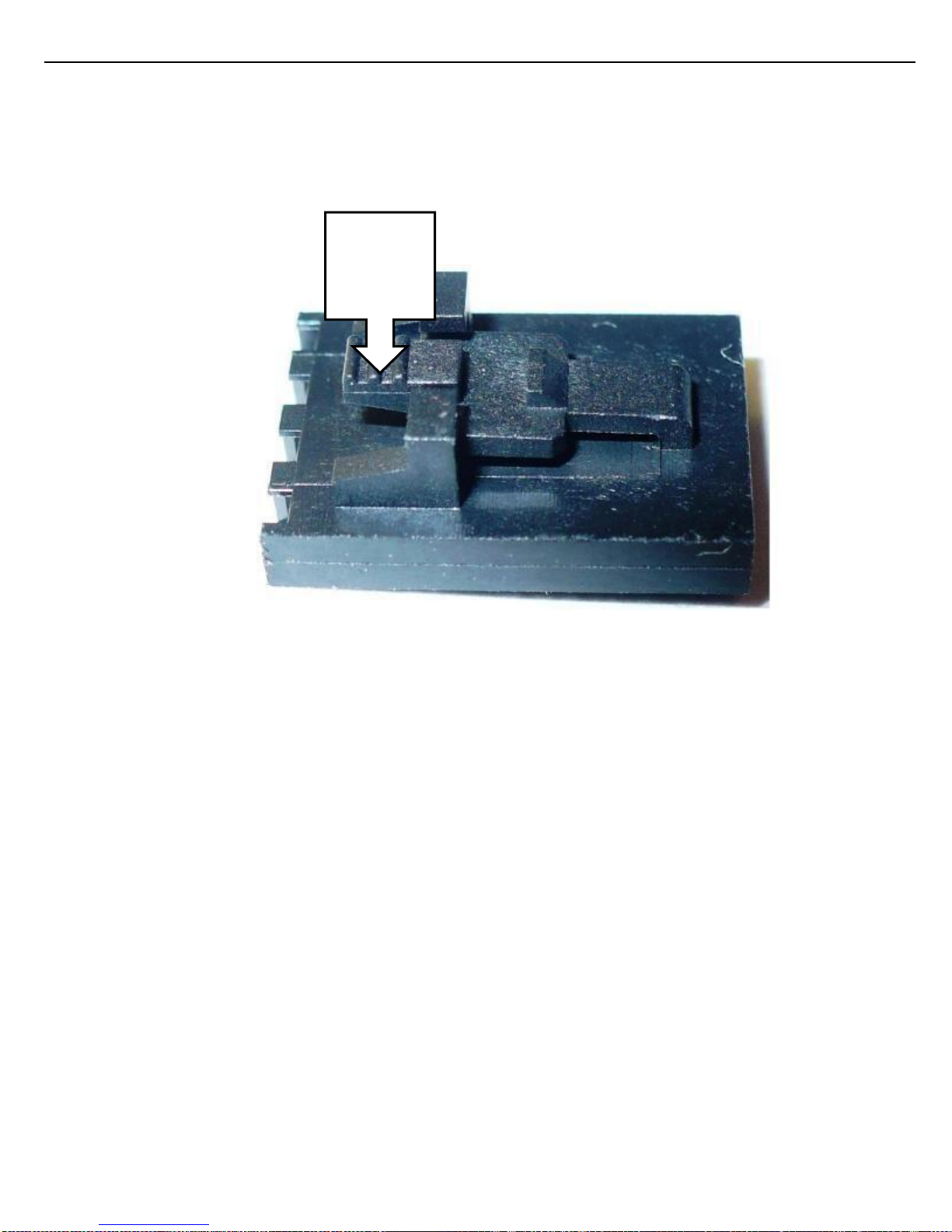
1. To remove the LED cable from J2 on the ACR-FID _COMBO board or J1 on the LED PC board, push
in the locking tab.
2. While depressing the tab pull the plug out of the connector.
Figure 6.1 LED CABLE CONNECTOR
DEPRESS
THE TAB
Page 29

Chapter 6 – Service and Repair
29
ACR II Installation Guide: 20180711 Part # 6057
6.2.2 ACR-FID_COMBO PC BOARD REMOVAL
Removal:
NOTE: Using a magnetic screwdriver is very helpful in retaining the screws during removal and installation.
1. Ensure that the area is non hazardous before opening the enclosure.
2. Record dip switches settings on SW1 and SW2.
3. Remove Mains power supplying TB1.
4. Remove power (if connected) from TB6.
5. Disconnect plugs TB1 and TB6 (if connected to field devices).
6. Disconnect Serial Communications plug connections from TB3 or TB4.
7. Disconnect the LED Cable (after pushing locking tab in see figure 6.1) from J2.
8. Disconnect the Card Reader cable from TB2
9. Remove the six ACR-FID_COMBO mounting screws.
10. Carefully remove the ACR-FID_COMBO board and place in an antistatic bag.
Installation:
1. Set dip switches for SW1 and SW2 on the new PC board.
2. Carefully insert the ACR-FID_COMBO board into the enclosure.
3. Install the six mounting screws.
4. Connect the LED cable to J2.
5. Connect Card Reader cable to TB2.
6. Connect the Serial Communication cable to the appropriate connector TB3 or TB4.
7. Connect Input plug to TB5 if used.
8. Connect Output plug to TB6 if used.
9. Connect the Mains Power plug to TB1.
Page 30
Chapter 6 – Service and Repair
30
ACR II Installation Guide: 20180711 Part # 6057
6.2.3 LED PC BOARD REPLACEMENT
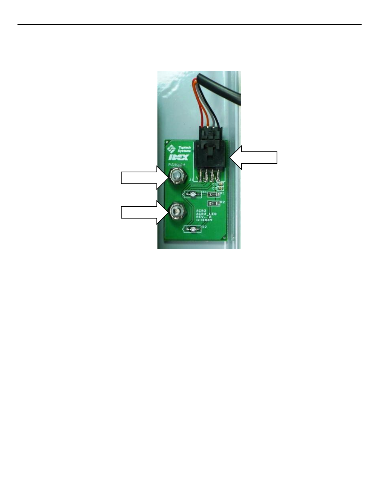
1. Disconnect LED cable (after pushing locking tab in see figure 6.1) from J1 on the LED PC Board.
2. Remove the two nuts holding down the LED PC Board from the threaded studs.
Figure 6.2 LED PC BOARD
3. Lift LED PC Board off threaded studs and place in an antistatic bag.
4. Place new LED PC Board on threaded studs ensuring components side of PC Board is visible.
5. Install nuts on threaded studs.
6. Plug the LED cable into J1.
REMOVE
REMOVE
J1
Page 31
Chapter 6 – Service and Repair
31
ACR II Installation Guide: 20180711 Part # 6057
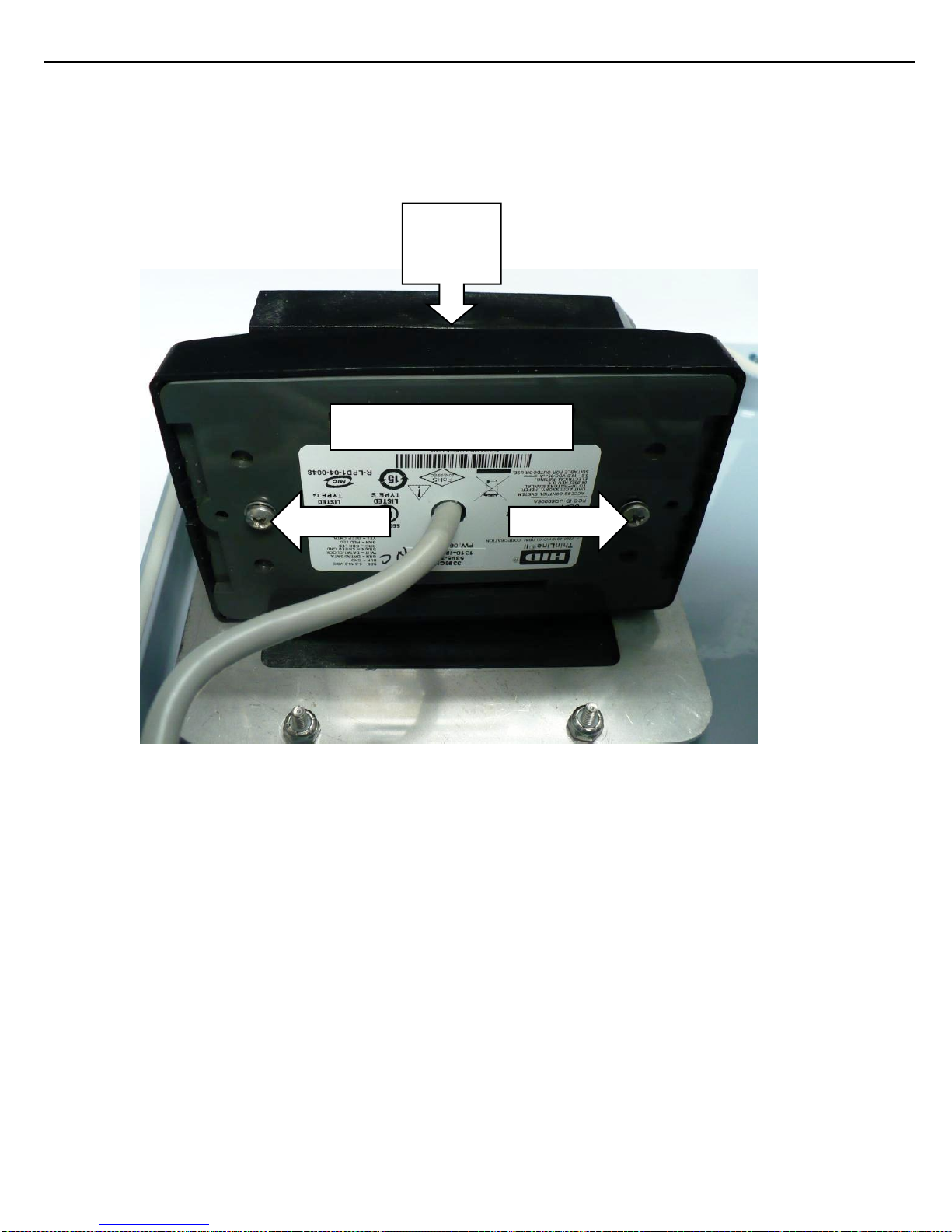
6.2.4 PROX READER THINLINE II REPLACEMENT
1. Unplug the card reader cable from TB2 on the ACR-FID_COMBO PC board.
2. Remove both screws from the back of the card reader.
3. Remove the card reader from the Card Holder.
Figure 6.3 PROX READER THINLINE II
4. Place new card reader next to Card Holder and install both screws.
5. Plug card reader cable into TB2 on the ACR-FID_COMBO PC board.
CARD
HOLDER
PROX READER THINLINE II
REMOVE
REMOVE
Page 32
Chapter 6 – Service and Repair
32
ACR II Installation Guide: 20180711 Part # 6057
6.2.5 PROX READER RP15 REPLACEMENT
Removal:
To remove the card reader it is recommended that the cover assembly be removed first.
1. Unplug the card reader cable from TB2 on the ACR-FID_COMBO board.
2. Unplug the LED cable from J1 on the LED indicator board (on face plate). See figure 6.1 on how to unlock
the connector.
3. Remove the ground cable screw on the face plate.
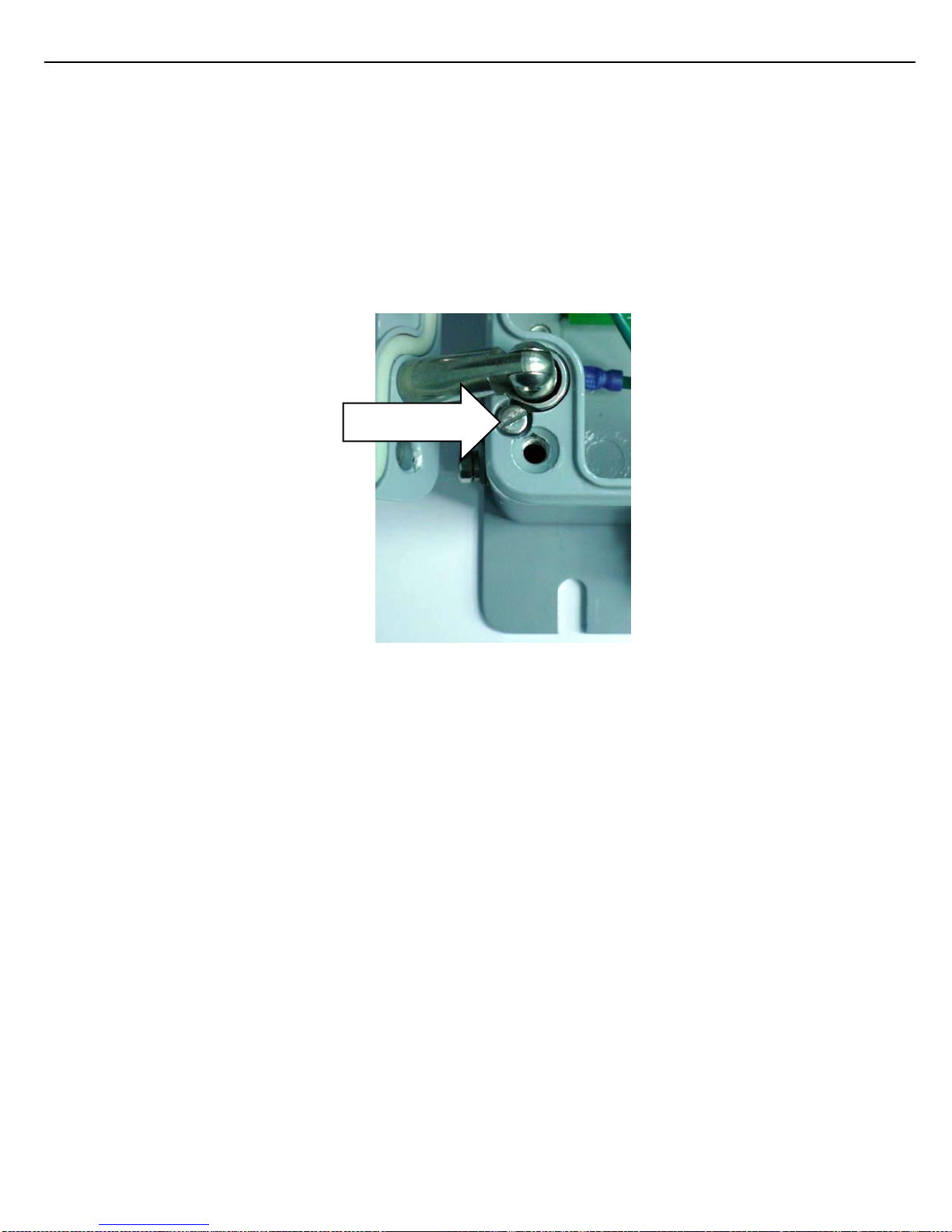
4. Remove the hinge retaining screws (small screw found adjacent to each hinge) from the base assembly.
Figure 6.4 HINGE RETAINING SCREW
5. Remove cover from base by pulling cover back away from the base.
Retaining screw
Page 33
Chapter 6 – Service and Repair
33
ACR II Installation Guide: 20180711 Part # 6057
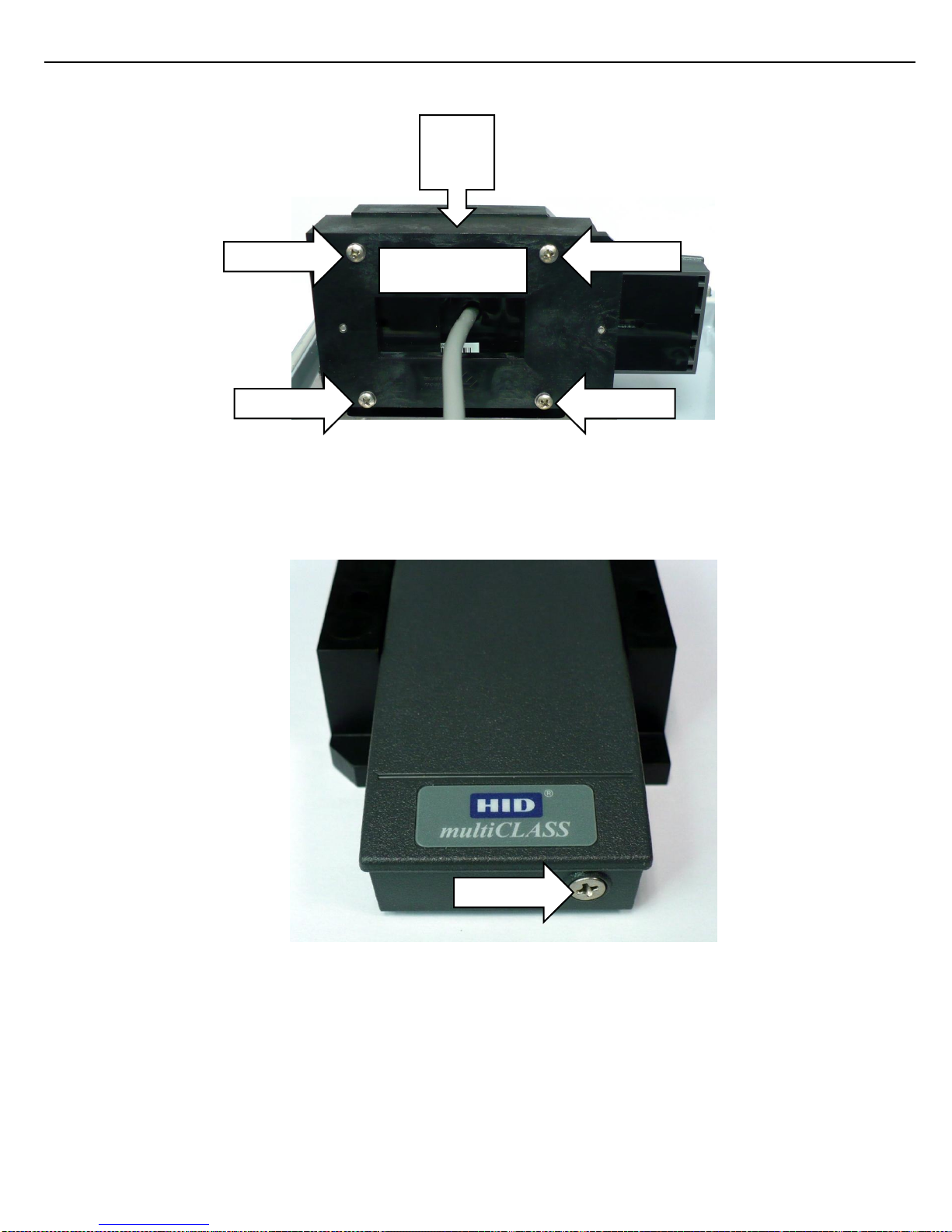
6. Remove the four retaining screws from the back of the Card Holder Back.
Figure 6.5 REMOVING CARD HOLDER BACK
7. Remove the Card Holder Back from the Card Holder.
8. Remove the card reader retaining screw from the end of the card reader.
Figure 6.6 PROX READER RP15 RETAINING SCREW
REMOVE
REMOVE
REMOVE
REMOVE
REMOVE
Card Holder Back
Card
Holder
Page 34
Chapter 6 – Service and Repair
34
ACR II Installation Guide: 20180711 Part # 6057
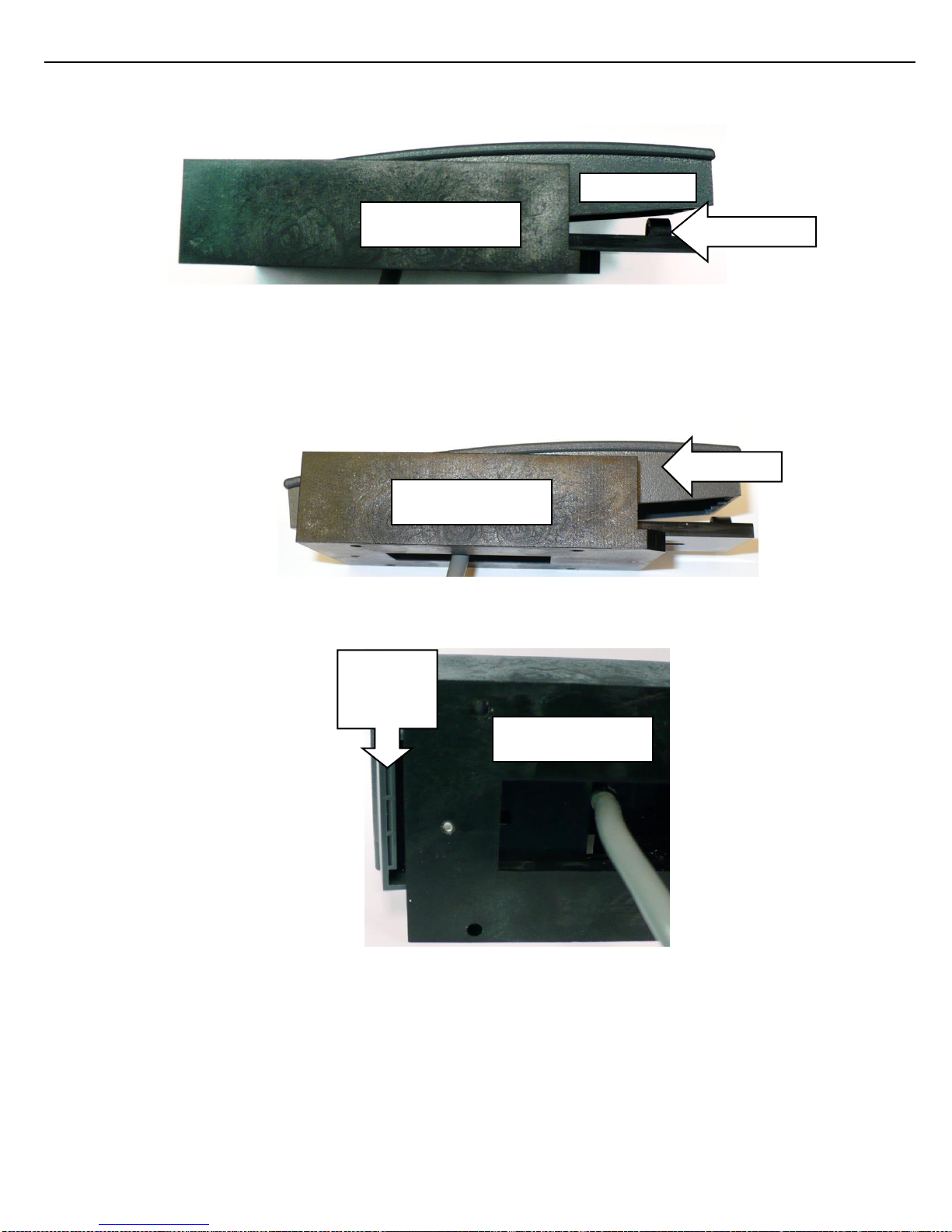
9. At the end were the screw was removed, pull the card reader up until it clears the Brass Insert on the
Card Holder Back..
Figure 6.7 BRASS INSERT ON CARD HOLDER BACK
10. While the card reader is elevated above the Brass Insert slide the card reader back until the card reader
tab clears the Card Holder Back.
Figure 6.8 UNLOCK PROX READER RP15
Figure 6.9 PROX READER RP15 TAB CLEAR POSITION
SLIDE
Card
Reader
Tab
Card Holder Back
Card Holder Back
Card Holder Back
Brass Insert
Page 35
Chapter 6 – Service and Repair
35
ACR II Installation Guide: 20180711 Part # 6057
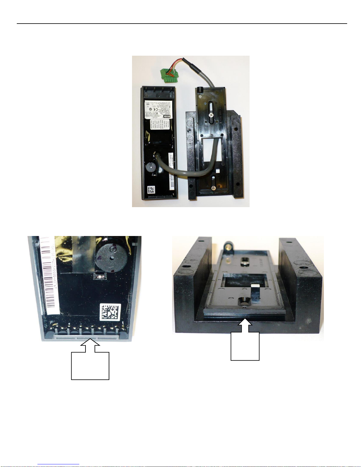
11. Pull the card reader off the Card Holder Back. Slide the card reader cable and connector threw the cut out
on the Card Holder Back.
Figure 6.10 PROX READER RP15 REMOVED
Figure 6.11 PROX READER RP15 TAB AND SLOT
Installation:
Tab
Slot
Card
Reader
Tab
Page 36
Chapter 6 – Service and Repair
36
ACR II Installation Guide: 20180711 Part # 6057
1. To install the new card reader, follow the removal instructions in reverse order until the Card Holder Back
is installed on the Card Holder. Then follow the following instructions.
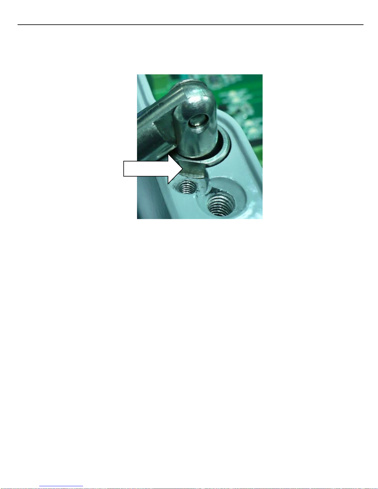
2. Slide hinges back into base making sure the cutout (notch) in the Retaining Hinge Ring is aligned with the
Retaining Screw and the base of notch is seated below the screw head level (see figure 6.12).
Figure 6.12 HINGE RETAINING RING CUTOUT
3. Install hinge retaining screws.
4. Reinstall the ground cable.
5. Reinstall the Prox Reader cable to TB2
6. Reinstall the LED cable to J1.
RING NOTCH
Page 37

Chapter 6 – Service and Repair
37
ACR II Installation Guide: 20180711 Part # 6057
6.3 TB2 PROXIMITY READER CONNECTION:
6.3.1 PROX READER THINLINE II:
TB2.1 - Prox Reader Beeper (Yellow)
TB2.2 - Prox Reader Clock (White)
TB2.3 - Prox Reader Data (Green)
TB2.4 - Prox Reader Card Present (Violet)
TB2.5 - Prox Reader 5V+ (Red)
TB2.6 - Prox Reader Ground (Black)
Note 1: The proximity wiring is made at the factory.
Note 2: The pin out is provided for troubleshooting or replacement only.
6.3.2 PROX READER RP15:
TB2.1 – Not used
TB2.2 - Prox Reader Clock (White)
TB2.3 - Prox Reader Data (Green)
TB2.4 - Jumper wire to TB2.6
TB2.5 - Prox Reader 5V+ (Red)
TB2.6 - Prox Reader Ground (Black)
Note 1: The proximity wiring is made at the factory.
Note 2: The pin out is provided for troubleshooting or replacement only.
Page 38
Chapter 7 – Appendix
38
ACR II Installation Guide: 20180711 Part # 6057
CHAPTER 7 APPENDIX
Figure 7.1 UNIT OUTLINE DRAWING – MOUNTING TEMPLATE
Page 39
Chapter 7 – Appendix
39
ACR II Installation Guide: 20180711 Part # 6057
Figure 7.2 UNIT OUTLINE DRAWING – FRONT VIEW
Page 40
Chapter 7 – Appendix
40
ACR II Installation Guide: 20180711 Part # 6057
Figure 7.3 UNIT OUTLINE DRAWING – SIDE VIEW
Page 41
Chapter 7 – Appendix
41
ACR II Installation Guide: 20180711 Part # 6057
Figure 7.4 UNIT OUTLINE DRAWING – BOTTOM VIEW
Page 42
Chapter 7 – Appendix
42
ACR II Installation Guide: 20180711 Part # 6057
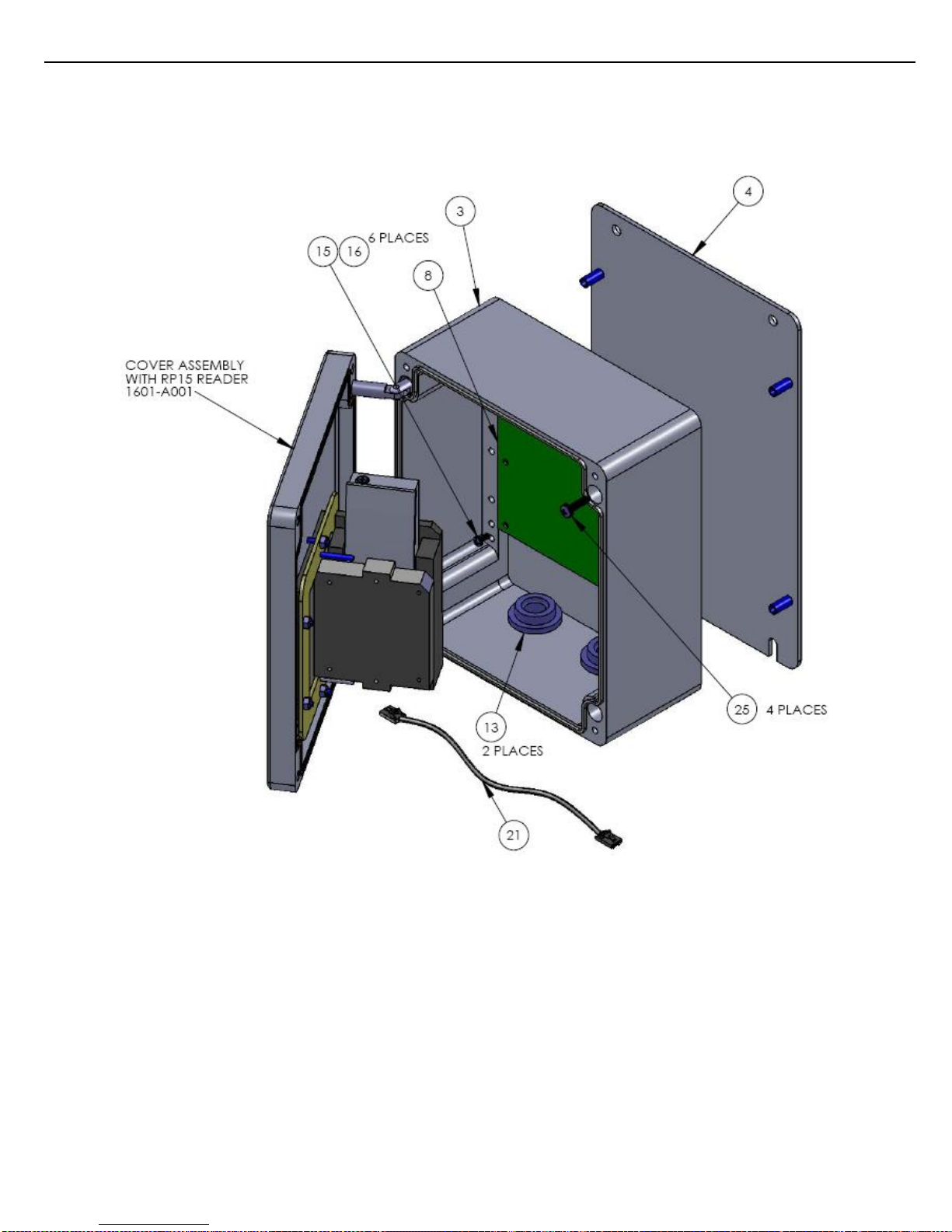
Figure 7.5 PROX READER RP15 TAB – TOP LEVEL VIEW
Page 43
Chapter 7 – Appendix
43
ACR II Installation Guide: 20180711 Part # 6057
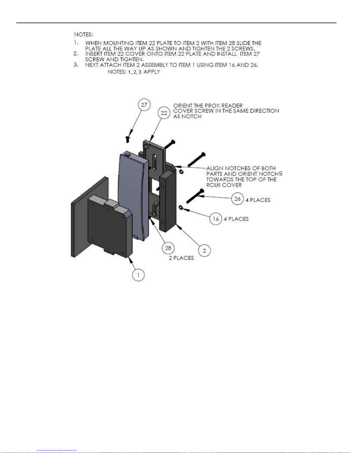
Figure 7.6 PROX READER RP15 TAB – EXPLODED VIEW
Page 44
Chapter 7 – Appendix
44
ACR II Installation Guide: 20180711 Part # 6057
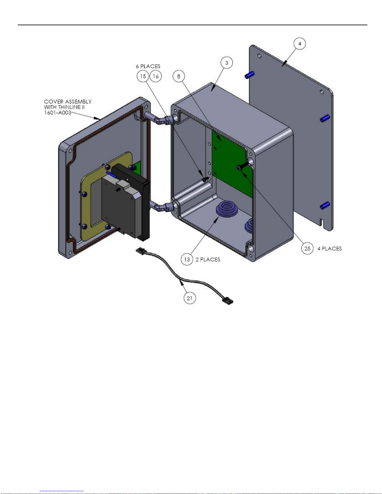
Figure 7.7 PROX READER THINLINE II – TOP LEVEL VIEW
Page 45
Chapter 7 – Appendix
45
ACR II Installation Guide: 20180711 Part # 6057
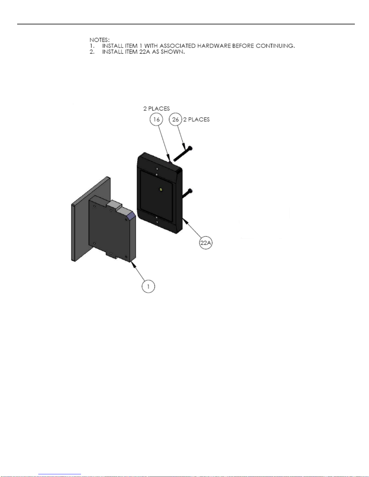
Figure 7.8 PROX READER THINLINE II EXPLODED VIEW
Page 46
Chapter 7 – Appendix
46
ACR II Installation Guide: 20180711 Part # 6057
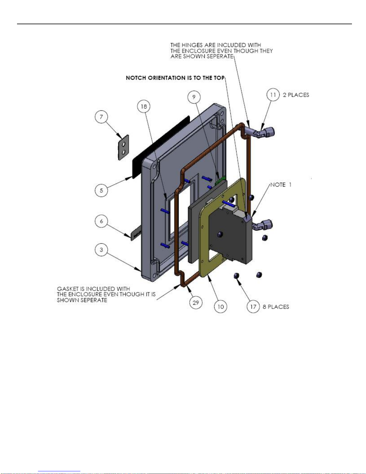
Figure 7.9 COVER – EXPLODED VIEW
Page 47

Chapter 7 – Appendix
47
ACR II Installation Guide: 20180711 Part # 6057
ITEM
#
Toptech
Part #
Reference
Number
Description
1
2153
Card Holder
2
2154
Card Holder Back
3
2243
Enclosure with Modifications
4
2239
Small External Mounting Plate
5
2245
Identification Label
6
2246
Instruction Label for Card Insert
7
2232
LED Label
8
2244
ACR-FID Combo PC Board Assembly (AC)
9
2297
LED PC Board Assembly
10
1241
Prox Bracket Stainless Steel
11 Internal Hinge w/screws w/enclosure
12
Cover Screw w/enclosure
13
1651
Myers Hubs 1/2" Aluminum (couplers)
14
1410
M6 - 1.0 x 10.0mm Philips screw w/base
15
0483
6-32 x 1/2" ss panhead Philips pcb mount
16
0490
#6 internal tooth star washer
17
0649
#6 nylon locking nut ss
18
0552
Silicone Rubber Adhesive Sealant, RTV, UL specific
19
2194
Ground Wire
20
1410
M6 - 1.0 x 10.0mm Philips screw (supplied with
base/cover)
21
2274
Cable, LED to Combo PCB Assembly
22
2249
Prox Reader RP15, Cable Length:
22A
0217
NOTE 1 Prox Reader Thinline II, Cable Length: 13"
23
1340
MCVR 1.5/6-ST-3.81 Plug for prox reader
24
0300
Heat Shrink 3/8" diameter for prox reader
25
1344
10-32 x 3/4 ss Philips panhead screw
26
1783
6-32 x 1 1/4" ss panhead Philips for card holder
assembly
27 6-32 x 3/8" flat head Philips w/Prox Reader
28 6-32 x 1/2" flat head Philips w/Prox Reader
29
2292
5 mm Cord Gasket, 31" inches/unit w/enclosure
NOTE:
1. Optional Prox Reader Item #2 Not Used, Item #26 use two screws
Figure 7.10 PARTS LIST
Page 48
Chapter 7 – Appendix
48
ACR II Installation Guide: 20180711 Part # 6057
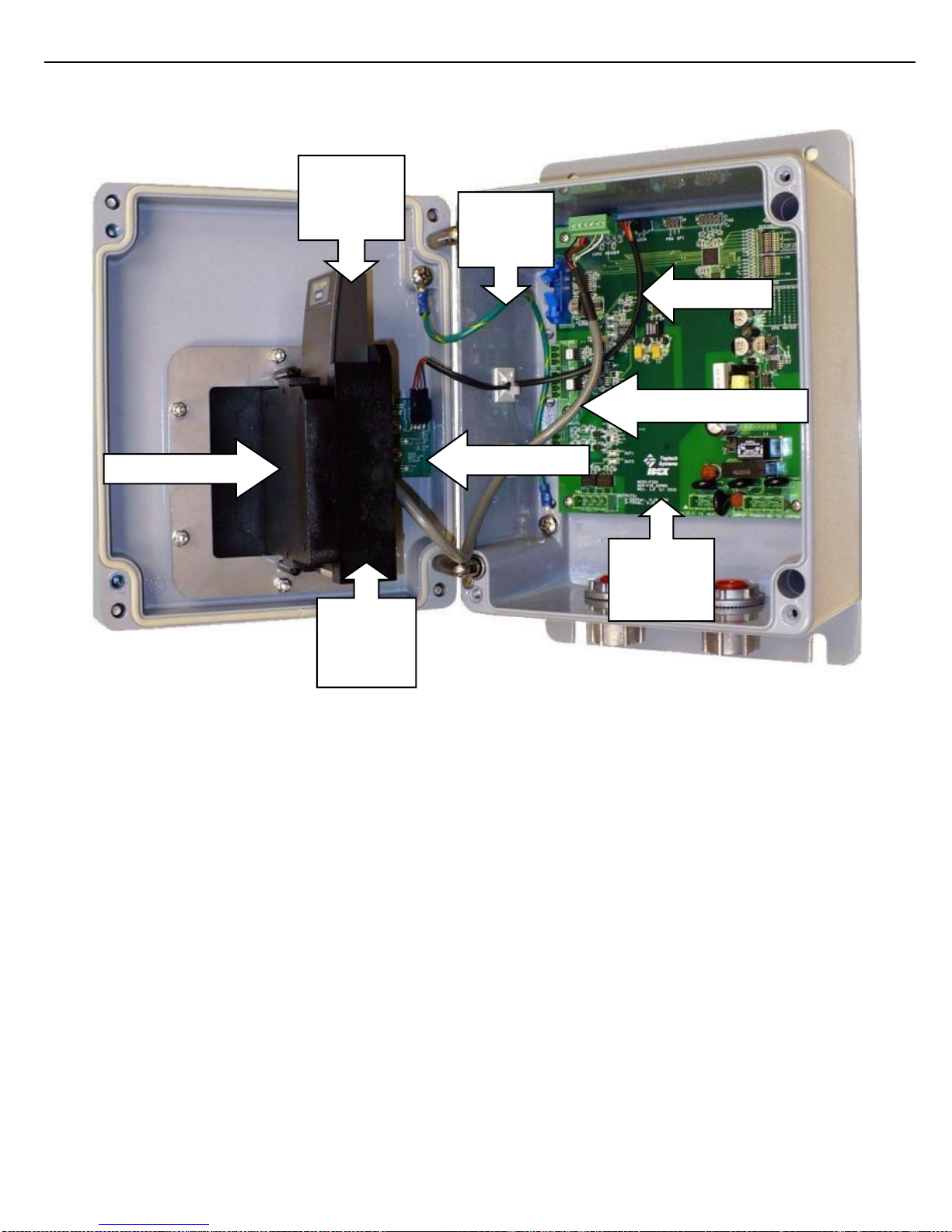
Figure 7.11 ACR II INSIDE VIEW
LED CABLE
CARD READER CABLE
GROUND
CABLE
CARD
HOLDER
BACK
ACR2
FID_COMBO
PROX
CARD
READER
CARD HOLDER
LED PC BOARD
Page 49
Chapter 7 – Appendix
49
ACR II Installation Guide: 20180711 Part # 6057
Figure 7.12 RP15 - STATUS LIGHT
Figure 7.13 Thinline - STATUS LIGHT
STATUS LIGHT
STATUS LIGHT
Page 50

Chapter 7 – Appendix
50
ACR II Installation Guide: 20180711 Part # 6057
CHAPTER 8 MANUAL REVISION HISTORY
Date
Description
09/30/2010
Release.
04/19/2016
Revised Declaration of Conformity (new directive dates in effect 4/20/2016)
 Loading...