

Topsoaring New Technology TOPSKY DLG Installation Manual
Topso aring New Technolo gy C o., LTD Top Sky D LG Inst all G uide
TOPSKY DLG Installation Manual
Topsk yIns tal lGuid e- (Englis h version). doc Page 1 of 40
Topso aring New Technolo gy C o., LTD Top Sky D LG Inst all G uide
Topsk yIns tal lGuid e- (Englis h version). doc Page 2 of 40

Topso aring New Technolo gy C o., LTD Top Sky D LG Inst all G uide
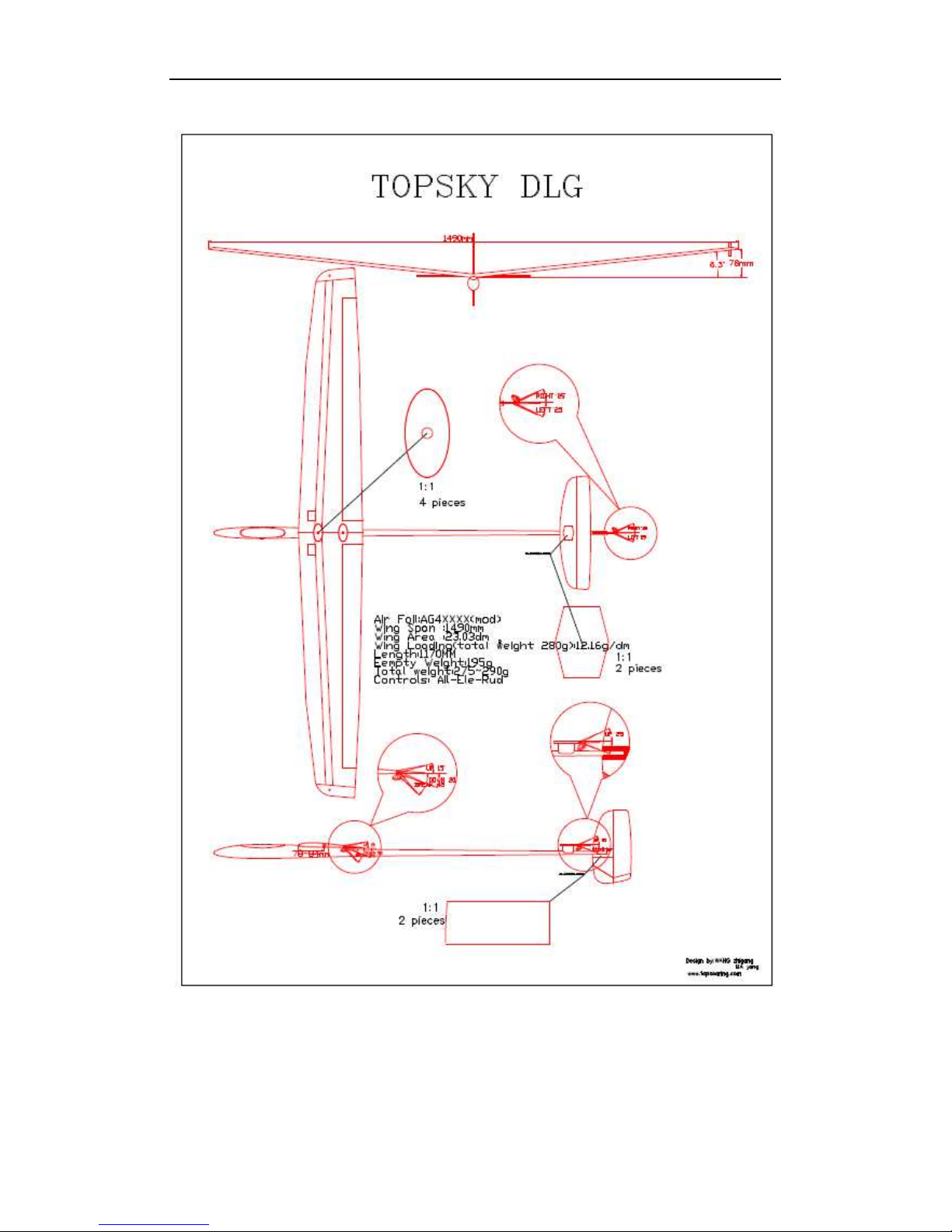
Specs:
Airfoil - AG4XXXX
Wingspan - 1490mm
Length - 1180mm
Wing area - 22.84 dm2
Weight - 1 95 g
AUW - 260£-280g
Wing load - 11.38g/dm2£-12.26g/dm2
Recommend RC equipment:
Servo:
Futaba: 3108, 3110, 3114, S3154, JR-SM22, DS285
Diamond: D 4.7, D 60
Hitec: HS45, HS55, HS5055
Battery:
C-4-KAN400 2/3AAA-Double Stick-18AWG Wire-Hitec male
Receiver:
Berg: 4, 7,
Corona: 420II, 620II, 820II,
JR-620
Hitec: 05s, 6s
Wings: 2 x Dymond D60 – 19:95 - Dymond D 60
2 x Dymond D 4.7 Power - Dymond D 4.7
Elevator: Hitec HS-55 - Hitec HS-55
Rudder: Hitec HS-55
Topsk yIns tal lGuid e- (Englis h version). doc Page 3 of 40

Topso aring New Technolo gy C o., LTD Top Sky D LG Inst all G uide
Attention: Because after the compound materials cure, there will be ammonia iris on the surface, which
affect the bonding strength afterwards. Please polish with sandpaper on all bonding surface.
1. Ta il I ns tall ation
1.1. Sand the top surface of stabilizer mount. Make sure it’s vertical to the side surface.
1.2. Sand the side surface, or you can make streamline as shown in the picture below.
1.3. Cover the tail boom with 300# sandpaper, then sand the groove of the stabilizer mount. Make
sure that the groove is parallel to the fuselage, and parallel to the outside surface of the tail boom.
And after bonding to the tail boom, the upper side of the mount should be parallel to the central
line of the tail boom.
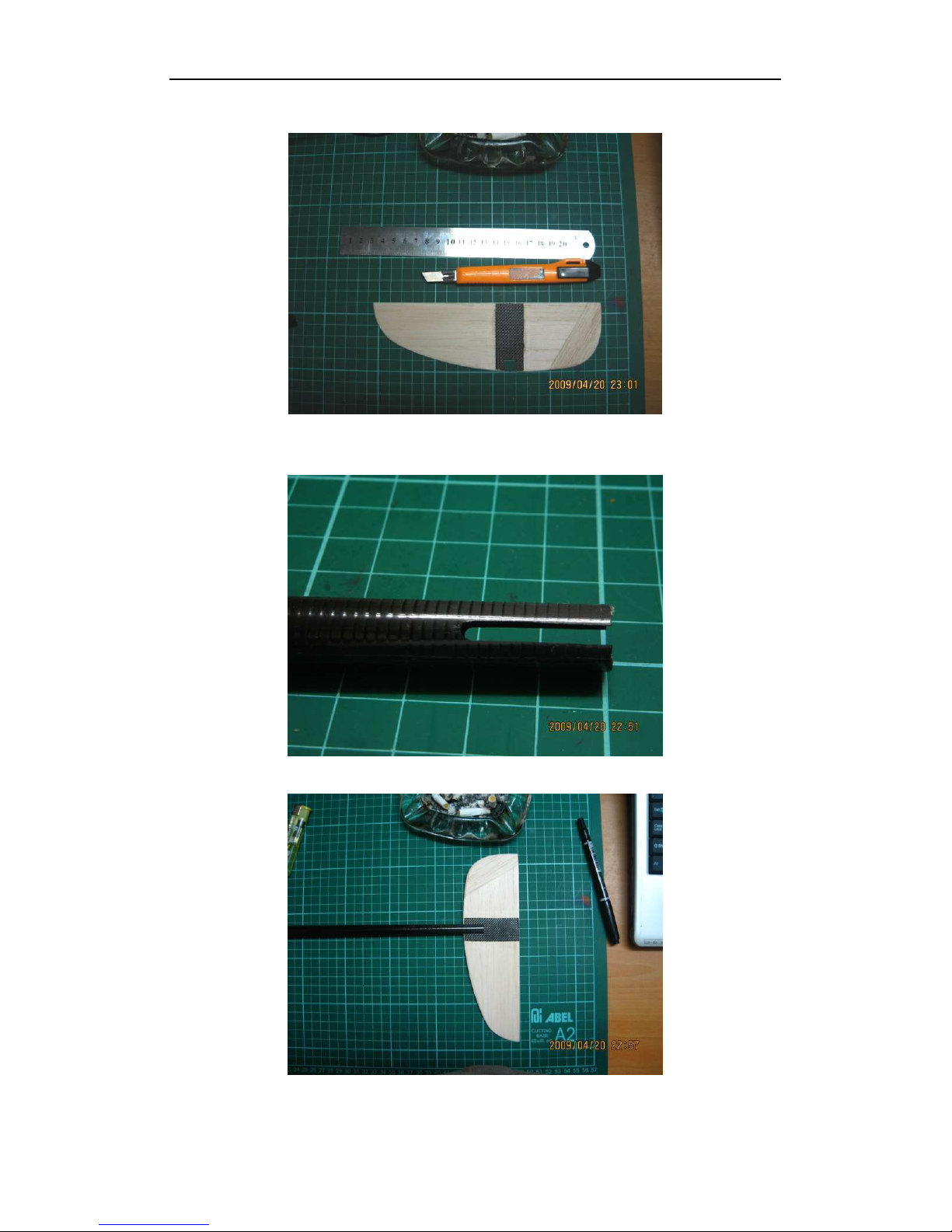
1.4. Polish, cut, or drill the tail as you prefer. We suggest that you may make the rear end of the tail
thinner. It should weigh 12g after sanding.
1.5. Cut the elevator. You may decide the size and shape based on your favorite design. Cutting the 2
holes on the balsa is recommended.
Topsk yIns tal lGuid e- (Englis h version). doc Page 4 of 40

Topso aring New Technolo gy C o., LTD Top Sky D LG Inst all G uide
1.6. Sand the gap and bevel for the hinge.
1.7. Bond the carbon cloth to the tail. The weight of the tail should be 13g.
1.8. Wa it f or t he gl ue t o ha rde n wit h he avy we igh ts.
Topsk yIns tal lGuid e- (Englis h version). doc Page 5 of 40
Topso aring New Technolo gy C o., LTD Top Sky D LG Inst all G uide
1.9. Make a slot on the front end of the vertical tail. The width is the same as the diameter of the tail
boom, and the length is 10mm.
1.10. Slotting the tail boom: Width 2.5mm, length 20mm. Make sure the edge of the two slots are
smooth. You may sand it with 300 grit sandpaper.
1.11. Join the tail boom and the vertical tail. Sand or remove small sections until it fits.
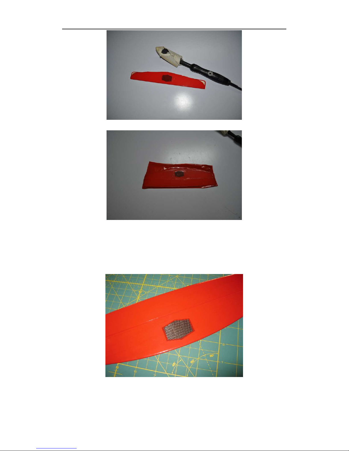
1.12. First cover the tail side with hinge.
Topsk yIns tal lGuid e- (Englis h version). doc Page 6 of 40
Topso aring New Technolo gy C o., LTD Top Sky D LG Inst all G uide
1.13. Then, cover the other side. The weight of tail set with films should be 14g.
1.14. Cut the covering of both sides of the vertical tail: 2mm inside the edge of the carbon, cut from
the front to the end of the tail boom.
1.15. Bond the tail boom and the vertical tail, with fiberglass and epoxy.
1.16. Cut the covering of the stabilizer: 2mm inside of the carbon.
1.17. Fix the tail on your working board. Check the joint:
The stabilizer should be parallel to the center line of the tail boom, or it may have an angle of
-1 degree.
The hinge of the elevator should be vertical to the tail boom.
The center line of the tail boom should be right in the middle of the stabilizer.
Topsk yIns tal lGuid e- (Englis h version). doc Page 7 of 40
Topso aring New Technolo gy C o., LTD Top Sky D LG Inst all G uide
The vertical tail should be vertical to the stabilizer.
The vertical tail should be on the same surface as the center line of the fuselage.
The hinge of the vertical tail should be vertical to the center line of the tail boom.
1.18. Te mp or ar il y j oi n t he ve rt ic al ta il an d t he ta il bo om with tape. Then bond the tail boom and the
vertical tail from both sides using the provided fiberglass and 30min epoxy.
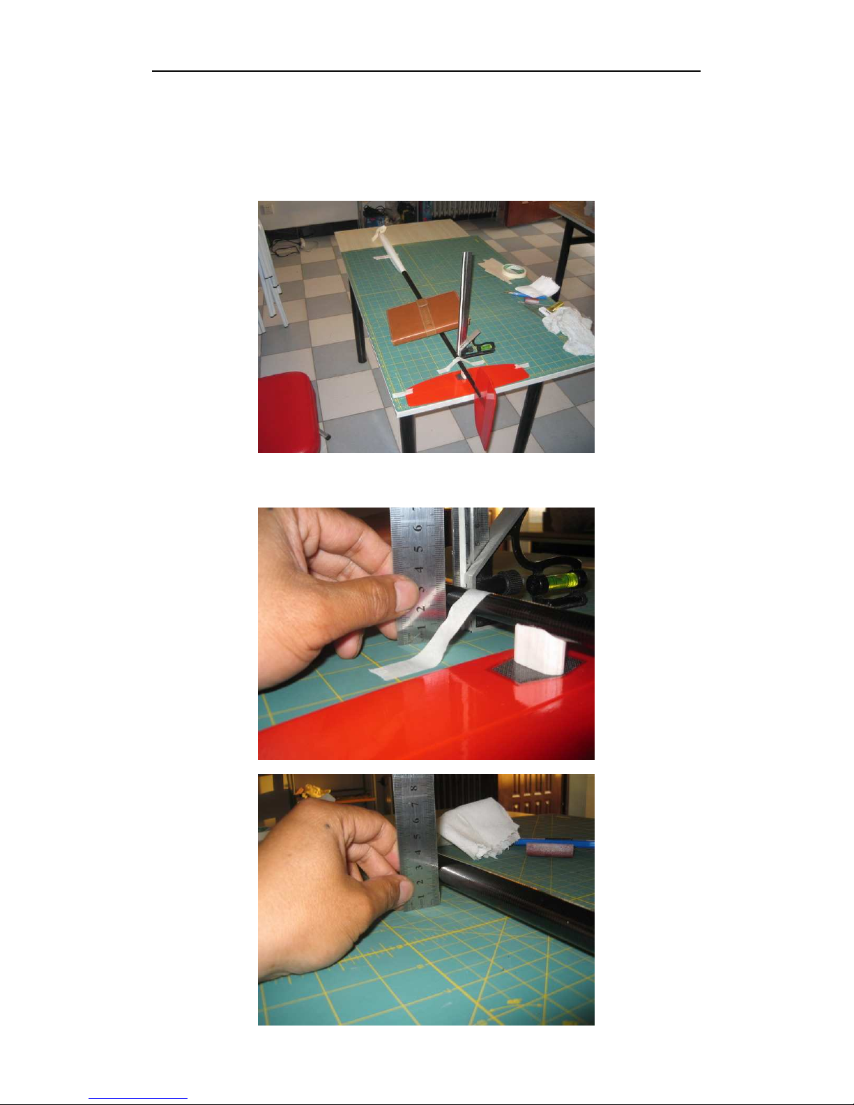
1.19. Lay the fuselage flat on the desk, with the vertical tail up side down.
1.20. Adjust the center line of the tail boom, to make it parallel to the desk surface and also parallel to
the scale mark on the working board.
Topsk yIns tal lGuid e- (Englis h version). doc Page 8 of 40
Topso aring New Technolo gy C o., LTD Top Sky D LG Inst all G uide
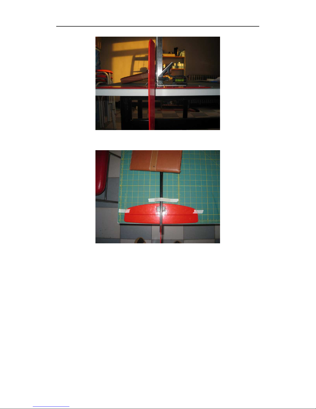
1.21. With a ruler, make the vertic al tail be vertical to the desk.
1.22. With the sca le mark, adjust the stab il izer and the mount. When the stabilizer is flat on the desk,
the hinge of the elevator is vertical to the tail boom.
Topsk yIns tal lGuid e- (Englis h version). doc Page 9 of 40
Topso aring New Technolo gy C o., LTD Top Sky D LG Inst all G uide
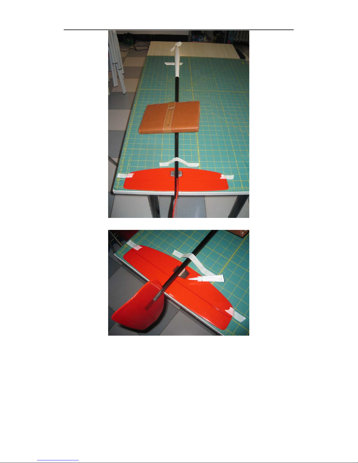
1.23. Bond the stabilizer mount and the tail boom with fast glue.
1.24. Cut appropriate size of fiberglass with a paper template.
Topsk yIns tal lGuid e- (Englis h version). doc Page 10 of 40

Topso aring New Technolo gy C o., LTD Top Sky D LG Inst all G uide
1.25. Apply a thin layer of epoxy on the boom, stabilizer carbon and the mount.
1.26. Join the tail boom and the mount to the bottom of the stabilizer with epoxy and fiberglass.
Wait ing fo r it to c ur e.
2. Wing installation
2.1. Cut the servo mount based on your servo size.
Topsk yIns tal lGuid e- (Englis h version). doc Page 11 of 40

Topso aring New Technolo gy C o., LTD Top Sky D LG Inst all G uide
Topsk yIns tal lGuid e- (Englis h version). doc Page 12 of 40
 Loading...