

Top Signal TS111651, TS111652 Installation And Operation Manual
Top Signal
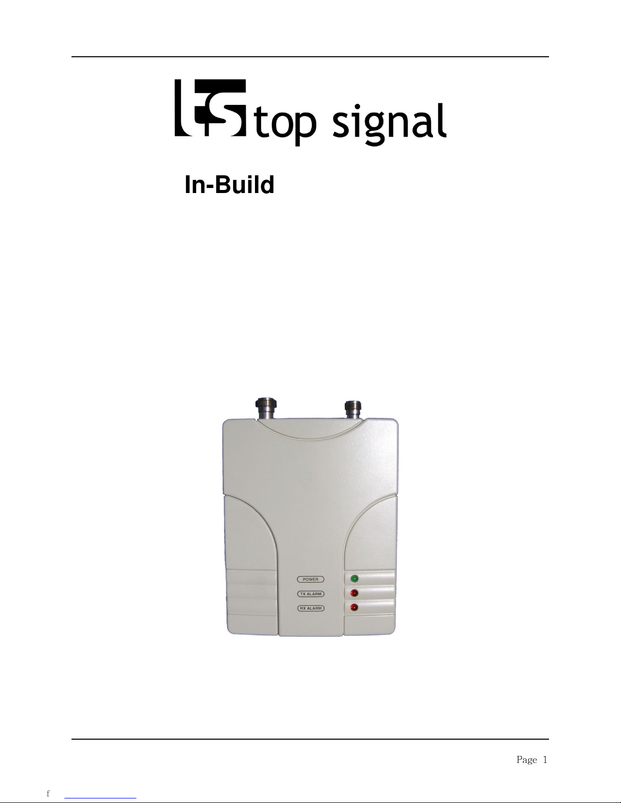
In-Building Repeaters
Model: TS111651 800MHz Single Band
Model: TS111652 1900 MHz Single Band
Installation and Operations Manual
For both TS111651 & TS111652
www.TopSignalProducts.com
Page 1

1. General Information
1.1 Introduction
1.2 Specifications
1.3 Description
2 Installation
2.1 Introduction
2.2 Unpacking and Inspection
2.3 Preparation for Use
2.4 Before Installation
2.5 Antenna Installation
2.6 Bi-directional amplifier Installation
2.7 Connectors
Top Signal
Table of Contents
2.8 Installation Example
3 Operation
3.1 Introduction
3.2 Operating Instructions
4 Trouble Shooting
5 Drawings
Page 2
Top Signal
General Information
1.1 Introduction
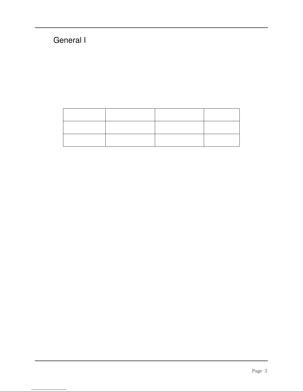
This manual provides information pertaining to the installation and operation of Top Signals’ TS111651
800MHz and TS11652 1900MHz “Ultra Slim Home Repeater” Bi-Directional Amplifiers. These units are
for CDMA, GSM, and TDMA modulations in the Cellular and PCS frequencies as shown in Table 1-1.
<Table 1-1: TS111651 / TS111652 Bi-Directional Amplifier >
*: Down Link is from base station to mobile
**: Up Link is from mobile to base station
Please Note: Both the TS111651 single-band 800MHz and the TS111662 single-band 1900MHz
amplifiers are setup and operated in the same manner. Going forward, this manual will refer to these
amplifiers as “Top Signal 65”.
Model Number
TS111651 869 ~ 894 MHz 824 ~ 849 MHz
TS111652 1930 ~ 1990 MHz 1850 ~ 1910 MHz
Down Link*
Frequencies
Up Link**
Frequencies
Modulation
CDMA,GSM
,TDMA
CDMA,GSM
, TDMA
Page 3
Top Signal
ITEM
SPECIFICATION
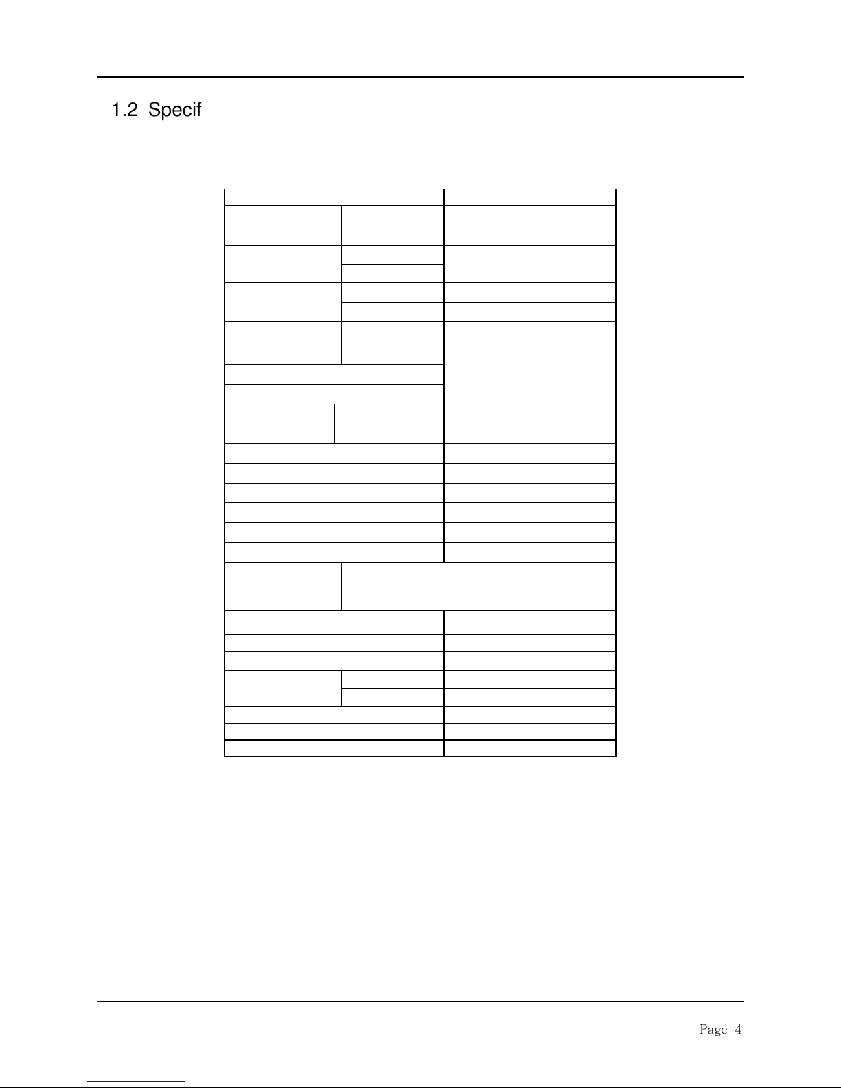
1.2 Specifications
TS111651 Specifications – 800MHz Single Band
Frequency
Input Power
Linear Gain
(Center Freq.)
Output Power
(Center Freq.)
Up / Down link ALC Range > 25 dB
Gain Flatness < 5 dB max (p – p)
Spurious
1 dB Compression + 22 dBm
3rd Order Intercept + 31 dBm
Down / Up Shutdown Level
Noise Figure, Typical < 5 dB
Propagation Delay
VSWR, Typical < 1.6 : 1
Alarm & Status
Power Consumption 5.3 V / 750 mA
Input Voltage (Adapter) DC 5.3 V / 1.8 A
RF Connectors N-Type Connector
Temperature
Dimensions( W x H x D , inch) 5.8” x 4.6” x 1.9”
Weight 1.4 Kg ( 3.1 lb )
FCC Type Acceptance Q4EUHSR-800H
Down Link 869 ~ 894 MHz
Up Link 824 ~ 849 MHz
Down Link - 28 dBm max/Total
Up Link - 28 dBm max/Total
Down Link 65 dB ( ±1 dB )
Up Link 65 dB ( ±1 dB )
Down Link
Up Link
Fc ± 750 KHz -45 dBc ( RBW =30 KHz )
Fc ± 1.98 MHz -50 dBc ( RBW =30 KHz )
GREEN ON : Power Normal
RED 1 ON : Down link Fail
RED 2 ON : Up link Fail
Operating
Storage
+ 12 dBm/CDMA1FA
+14 dBm ( ±1 dB)
< 1 µs max
-10 °C to 40 °C
-30 °C to 80 °C
Page 4
Top Signal
ITEM
SPECIFICATION
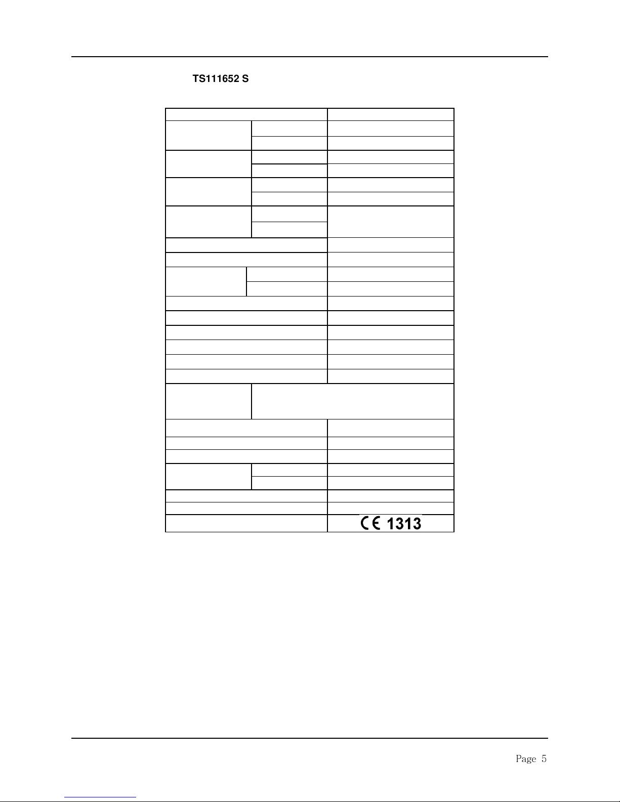
TS111652 Specifications – 1900MHz Single Band
Frequency
Input Power
Linear Gain
(Center Freq.)
Output Power
(Center Freq.)
Up / Down link ALC Range > 25 dB
Gain Flatness < 5 dB max (p – p)
Spurious
1 dB Compression + 22 dBm
3rd Order Intercept + 31 dBm
Down / Up Shutdown Level
Noise Figure, Typical < 5 dB
Propagation Delay
VSWR, Typical < 1.6 : 1
Alarm & Status
Power Consumption 5.3 V / 900 mA
Input Voltage (Adapter) DC 5.3 V / 1.8 A
RF Connectors N-Type Connector
Temperature
Dimensions( W x H x D , inch) 5.8” x 4.6” x 1.9”
Weight 1.4 Kg ( 3.1 lb )
CE Mark
Down Link 1930 ~ 1990 MHz
Up Link 1850 ~ 1910 MHz
Down Link - 28 dBm max/Total
Up Link - 28 dBm max/Total
Down Link 65 dB ( ±1 dB )
Up Link 65 dB ( ±1 dB )
Down Link
Up Link
Fc ± 885 KHz -45 dBc
Fc ± 1.98 MHz -50 dBc
GREEN ON : Power Normal
RED 1 ON : Down link Fail
RED 2 ON : Up link Fail
Operating
Storage
+ 12 dBm/CDMA1FA
+14 dBm ( ±1 dB)
< 1 µs max
-10 °C to 40 °C
-30 °C to 80 °C
Page 5
 Loading...