

Page 1

EX-93211/93511/93711/93911User Manual
1
Tks!EX-93211/93511/93711/93911
Panel PC User Manual
Release Date Revision
Mar. 2006 V0.2
Aug. 2007 V0.3
®2005 TOPSCCC Technology, Inc. All Rights Reserved. Published in Taiwan
Page 2

EX-93211/93511/93711/93911User Manual
2
Warning!___________________________________
This equipment generates, uses and can radiate radio frequency energy and if not installed and
used in accordance with the instructions manual, it may cause interference to radio communications.
It has been tested and found to comply with the limits for a Class A computing device pursuant to
FCC Rules, which are designed to provide reasonable protection against such interference when
operated in a commercial environment. Operation of this equipment in a residential area is likely
to cause interference in which case the user at his own expense will be required to take whatever
measures may be required to correct the interference.
Disclaimer
This information in this document is subject to change without notice. In no event shall TOPSCCC
Technology Inc. be liable for damages of any kind, whether incidental or consequential, arising from
either the use or misuse of information in this document or in any related materials.
Electric Shock Hazard – Do not operate the machine with its back cover removed. There are
dangerous high voltages inside.
Page 3

EX-93211/93511/93711/93911User Manual
3
Table of Contents______________________
Warning!…………………………………………………………………………….……..….2
Disclaimer…………………………………………………………………………………….2
Chapter 1 Getting Started
1.1 Specifications……………………………………….……………………..5
1.2 Dimensions………………………………...………………………….......7
1.3 System Configuration……………………………………………………11
1.4 Installation of CD-ROM & HDD…………………………………….…..12
1.5 Installation of PCI Addon………………………………………………..13
1.6 Safety Precautions……………………….………………….……….. …14
1.7 Brief Description…………………………………………………….……14
Chapter 2 Hardware
2.1 Mainboard………………..…….……………………………………..…..16
2.2 Installations…….…………………………………….…………………...17
2.2.1 Installing CPU…….……………………...………………………….....17
2.2.2 Installing Memory………………………………………………..….....18
2.2.3 Installing Jumper…………………………………………………….....19
2.2.4 Connectors on Mainboard……………….…………………………....23
Chapter 3 BIOS Setup
3.1 BIOS Setup………….…………..…………………………………..…...…31
3.1.1 Standard CMOS Setup………………………….………………...…...33
3.1.2 Advanced BIOS Features……………...………………………….......36
3.1.3 Advanced Chipset Features…………………………………………...39
3.1.4 Power Management Setup…………………………………………....45
3.1.5 PnP/PCI Configuration………….………………….……….………....47
3.1.6 PC Health Status…………………………………………………….....48
3.1.7 Load Fail-Safe-Defaults….………………….………………...……....48
3.1.8 Load Optimized Defaults……...…………………………...................48
3.1.9 Set Supervisor Password………………………………..…...............48
3.1.10 Save & Exit Setup………………………………………………….…49
3.1.11 Exit without Saving……….………………….……….…………….…49
Page 4

EX-93211/93511/93711/93911User Manual
4
Chapter 4 _ Installation of Drivers
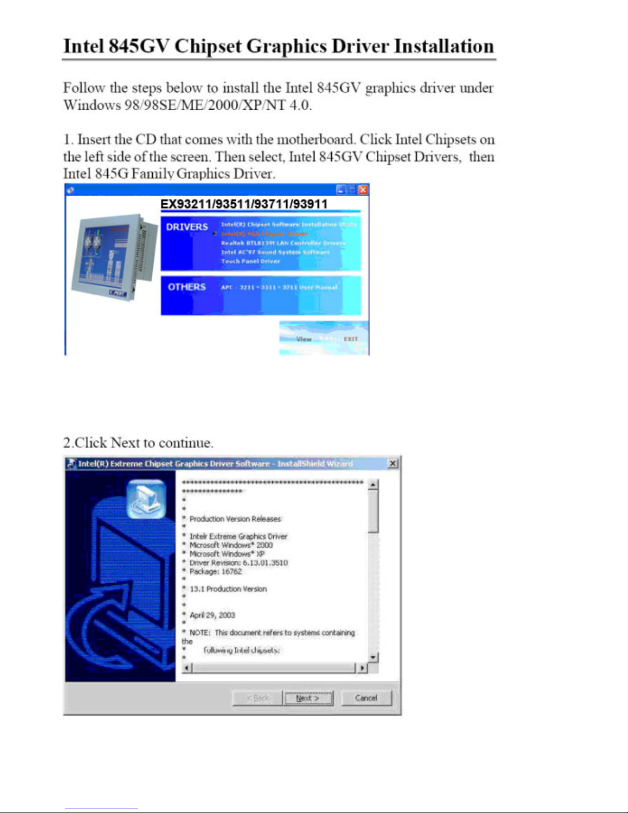
Intel Chipset Software Installation Utility…..………………………………54
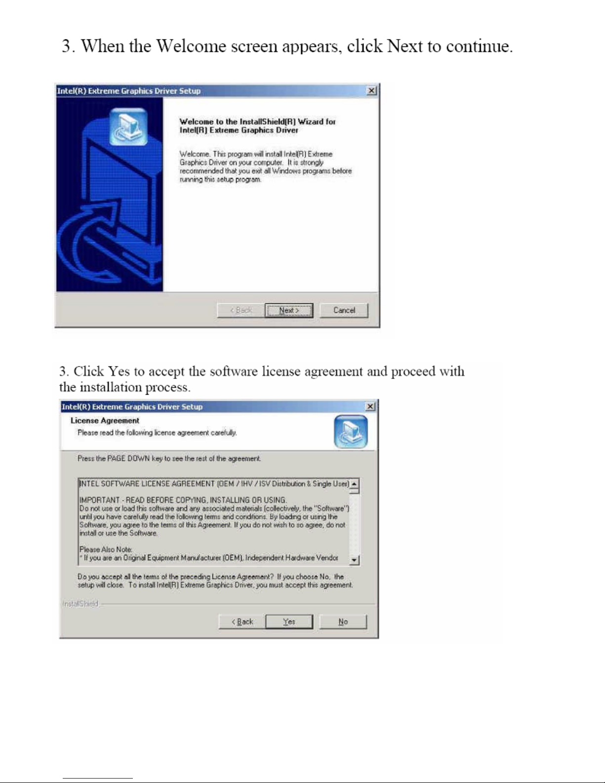
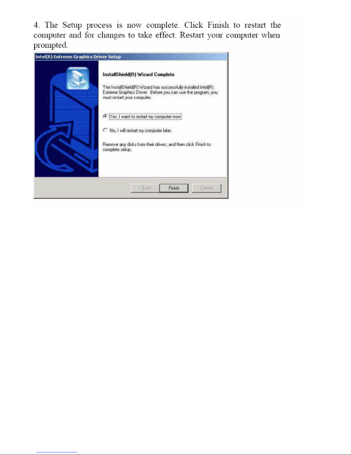
VGA Driver Installation…………..………………...………………………..54
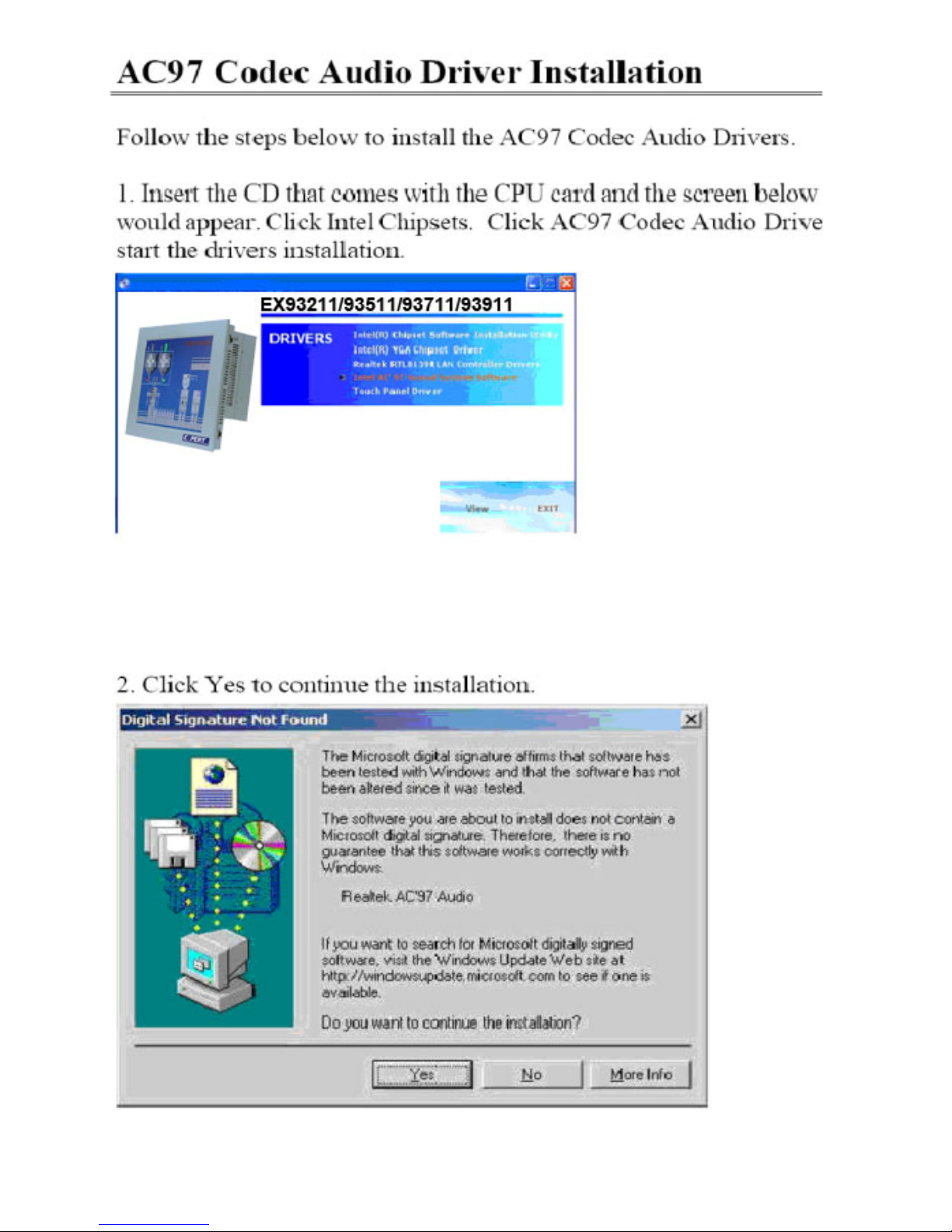
AC97 Codec Audio Driver Installation….………………………………….58
LAN Drivers Installation…………………………………..…………………60
Chapter 5 _ _Touch Screen Installation
5.1 Introduction to Controller Board..…………………………..……………61
5.2 Windows 2000/XP Driver Installation for Controller Board……..…….61
5.3 Configuring PenMount Windows 2000/XP Driver……………….……..65
5.4 Uninstall PenMount Windows 2000/XP Driver…………………….….. 72
Appendix _
A. Panel Mounting…………………………….…………..……………….....73
B. Rack Mounting……………………………………………………………..74
Figures
Figure 1.1: EX-93211 Dimensions……………………………………..…....7
Figure 1.2: EX-93511 Dimensions…………………………………………..8
Figure 1.3: EX-93711 Dimensions…………………………………………..9
Figure 1.4: EX-93911 Dimensions…………………………………………..10
Figure 1.5: System Configuration….………………………………………..11
Figure 1.6: Front View ……………………………………………………….14
Figure 1.7: Rear View………………………………………………………...15
Figure 2.1: Mainboard Overview………………………………………….....16
Figure 2.2 Installation of CPU………………………………………………..17
Figure 2.3 Installation of Memory Module……………………………..……18
Figure 2.4 Location of Jumpers……………………………………..............19
Figure 2.5 Location of Connectors……………………………………….…..23
Figure 5.1 Birdeye’s View of Control Board…………………………………61
Figure A Panel Mounting…………………………………………………....73
Figure B Rack Mounting (optional)…………………………………………74
Page 5

EX-93211/93511/93711/93911User Manual
5
Chapter 1 System
1.1 Specifications
Specs EX-93211 EX-93511 EX-93711 EX-93911
CPU Intel Celeron 2.4GHz Processor/Intel Pentium 4 2.0 ~ 2.4GHz CPU
Chipset Intel 845GV
Processor Side Bus Freq. 533MHz/400MHz
System Memory 1 x DDR Slot supporting up to 1GB 200/266/333 SDRAM
L2 Cache 128K/256K/512K, CPU integrated
Display Size
12.1” 800x600 TFT
LCD
15” 1024x768 TFT
LCD
17” 1280x1024
TFT LCD
17” 1280x1024
TFT LCD
Maximum Colors 262K 16.2M 16.2M 16.2M
Viewing Angle (H/V) 120˚/95˚ 140˚/125˚ 140˚/130˚ 140˚/140˚
Luminance (cd/m²) 300 400 300 250
Backlight Lifetime 50,000 Hours
Rating NEMA 4/IP65 certified Front Bezel
Touch Screen Type 8-wire Analog Resistive (optional)
Serial Port 4 x COM Port, COM4 reserved for Touch Screen
USB Port 4 x USB2.0 Port
Parallel Port 1 x Parallel Port supporting SPP/EPP/ECP
Drive Bays 1 x 40GB HDD and 1 x Slim CD-ROM
Keyboard & Mouse PS/2 Keyboard and Mouse Connectors
Digital I/O 4 in/4 out (optional)
BIOS Award BIOS, ACPI Supported
Watchdog Timer Generates system reset, 256 levels
LAN Realtek 8100BL LAN Controller (10/100Mb)
VGA Intel 845GV chipset integratred, AGP 4X
Expansion Slot 2 x PCI Expansion Slot
IDE Interface Ultra DMA 33/66/100 + Built-in ICH4
Audio ICH4 Integrated Audio with AC97 Codec
Power Supply 220W AC Universal 190~240V AC
Construction and Color Steel Chassis and Beige
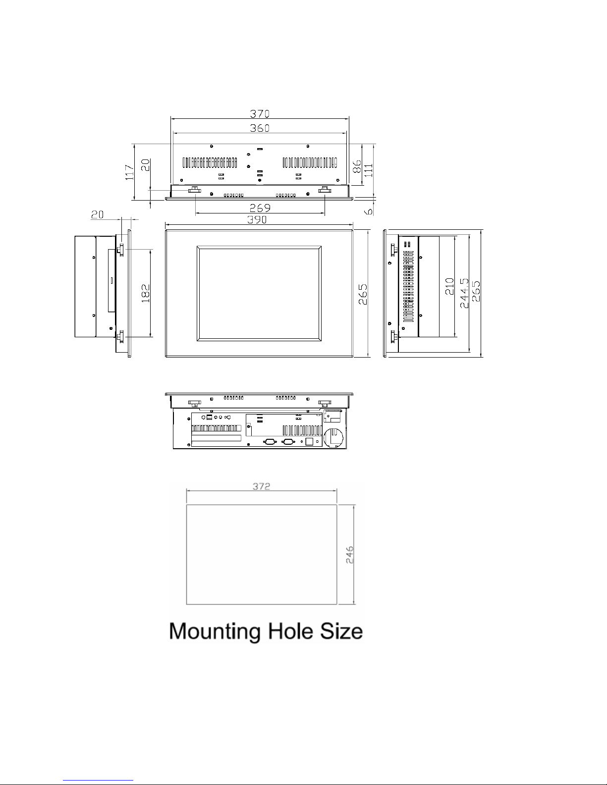
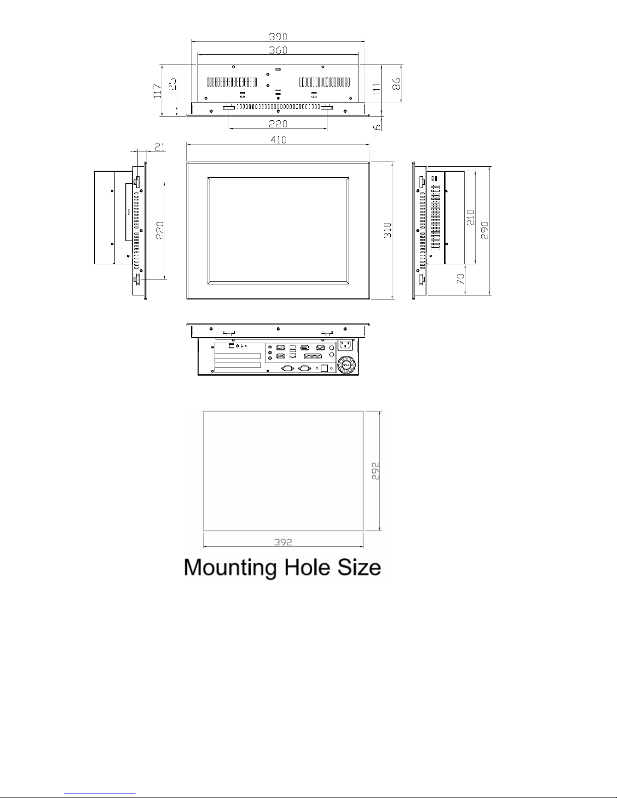
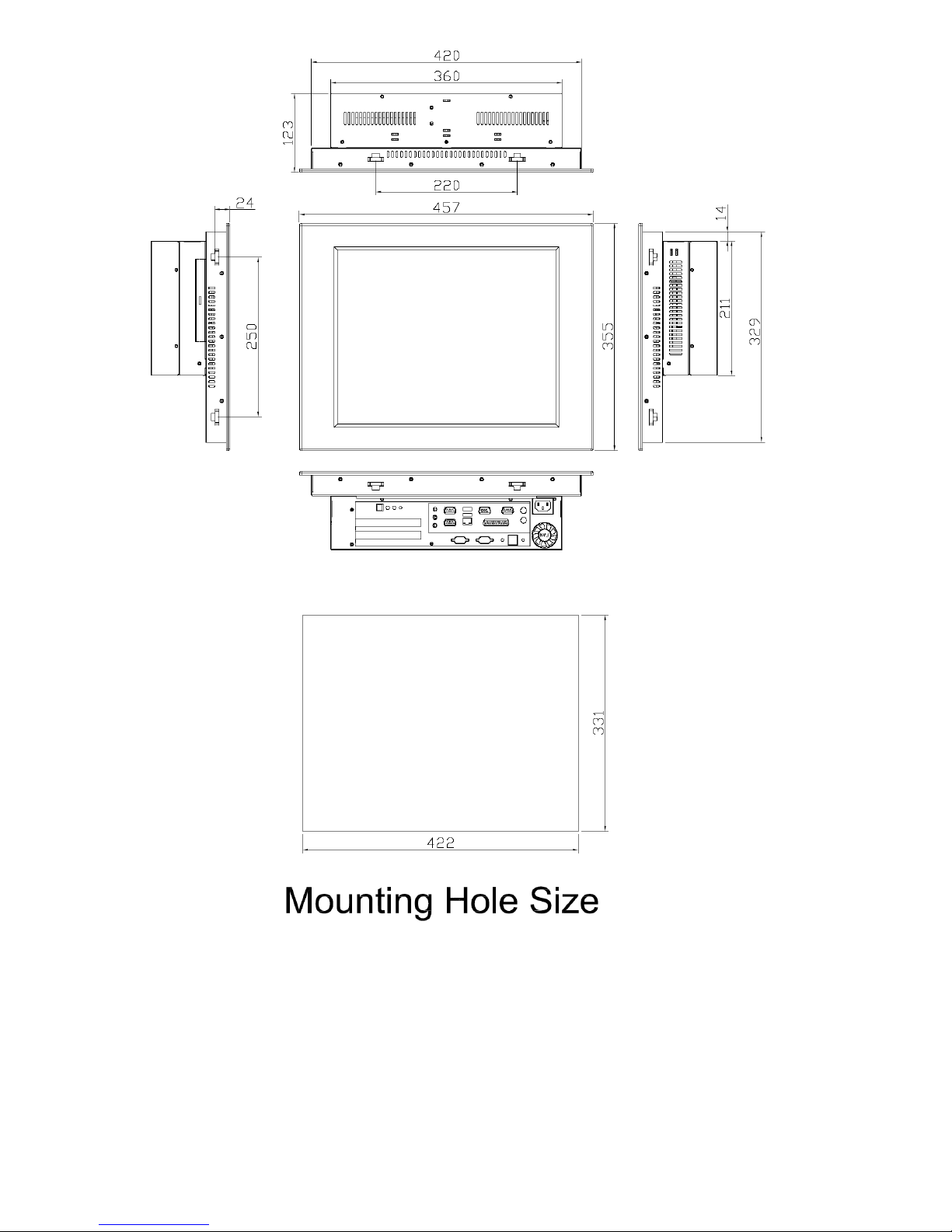
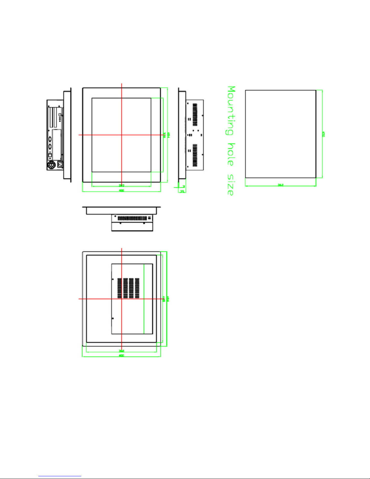
Dimensions (WxHxD) 390 x 265 x 111 410 x 310 x 117 457 x 355 x 123 484x400x123
Operating Temperature
0~50℃ (32℉~122℉)
Storage Temperature
-10℃~ 75℃ (14℉~167℉)
Model
Page 6

EX-93211/93511/93711/93911User Manual
6
Relative Humidity 10~90% (non-condensing)
Vibration 5~17Hz, 0.1” double amplitude displacement
17~640Hz, 1.5G acceleration peak to peak
Shock 10G acceleration peak to peak (11 millimeters)
Page 7
EX-93211/93511/93711/93911User Manual
7
1.2 Dimensions
Figure 1.1: Dimensions of the EX-93211
Page 8
EX-93211/93511/93711/93911User Manual
8
Figure 1.2: Dimensions of the EX-93511
Page 9
EX-93211/93511/93711/93911User Manual
9
Figure 1.3: Dimensions of the EX-93711
Page 10
EX-93211/93511/93711/93911User Manual
10
Figure 1.3: Dimensions of the EX-93911
Page 11
EX-93211/93511/93711/93911User Manual
11
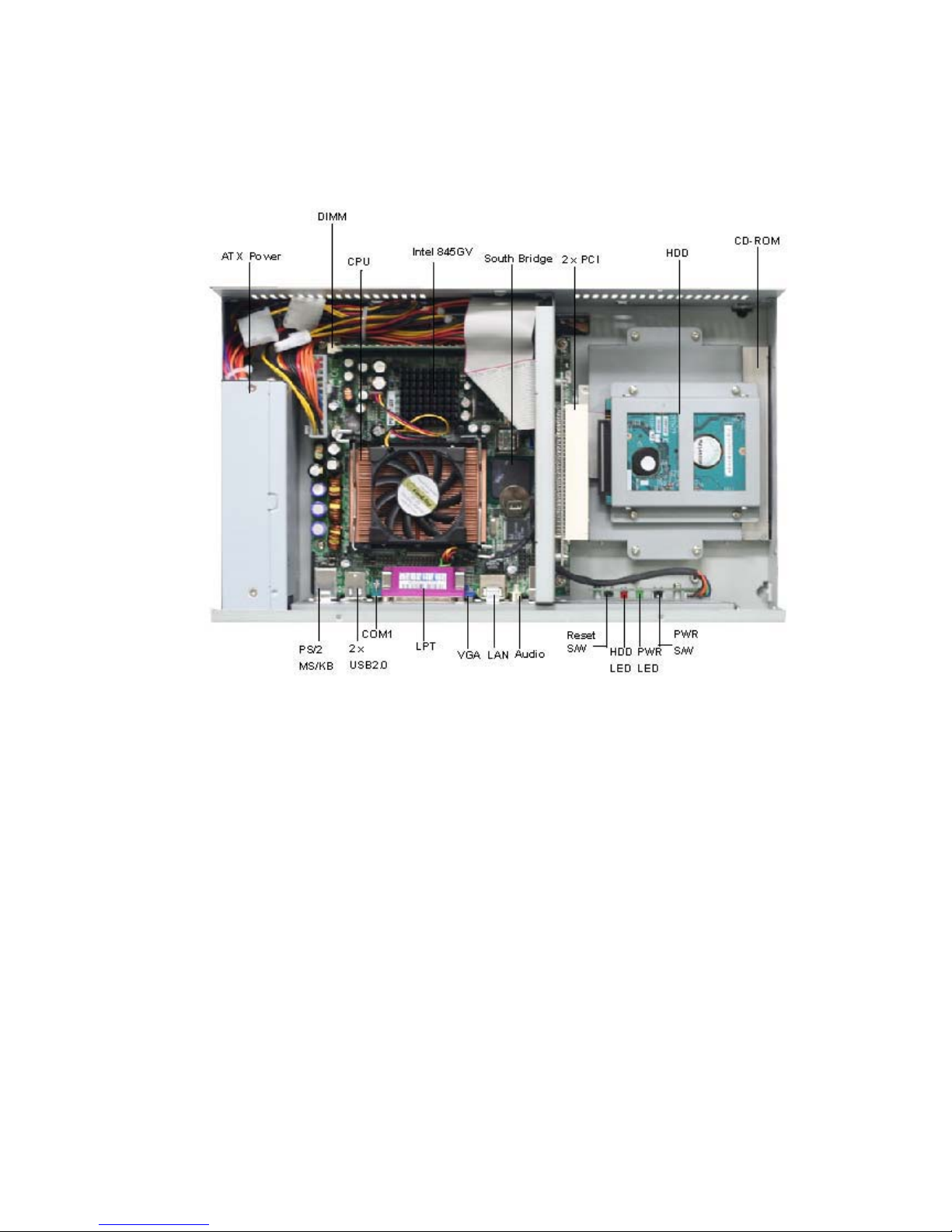
1.3 System Configuration
Figure 1.4: System Configuration of the EX-93211/93511/93711/93911
Page 12
EX-93211/93511/93711/93911User Manual
12
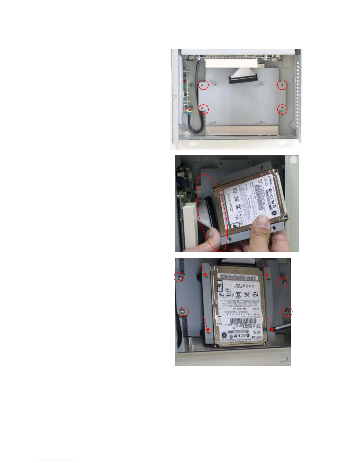
1.4 Installation of CD-ROM & HDD
Shown in the picture are the four
screws (as circled in red) that tighten or
loosen the bracket where the CD-ROM
is placed underneath. On top of the
bracket is where the HDD is placed. To
remove the CD-ROM, the HDD has to
be removed first.
Now slide the HDD into the bracket as
shown in the picture. After that, connect
the HDD to the 44-pin black IDE by
means of the cable, making sure the
red stripe of the cable is connected to
the pin 1 of the connector of the HDD
The red circles shown in the picture are
the screws that put the CD-ROM in
place. The arrows shown are where the
HDD, which is just placed on top of the
CD-ROM, is tightened.
CD-ROM
Page 13
EX-93211/93511/93711/93911User Manual
13
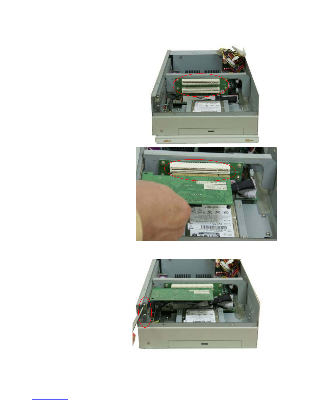
1.5 Installation of PCI Addon
Shown in the picture are the two PCI
expansion slots as circled. They can be
inserted with any addon for expanded
functions.
Now slide the addon into the PCI slot,
making sure the golden part faces the
slot. When both parts that are
interfaced together come into the right
contact, slightly push the addon into the
rail of the slot. This shows the addon is
already completely connected.
After sliding the addon into the PCI
expansion slot, get the two screws as
circled tightened to finish the
connection.
CD-ROM
Page 14
EX-93211/93511/93711/93911User Manual
14
1.6 Safety Precautions
Follow the messages below to avoid your systems from damage:
* Avoid your system from static electricity on all occasions.
* Prevent electric shock. Don‘t touch any components of this card when the card is power-on.
Always disconnect power when the system is not in use.
*Disconnect power when you change any hardware devices. For instance, when you connect
a jumper or install any cards, a surge of power may damage the electronic components or
the whole system.
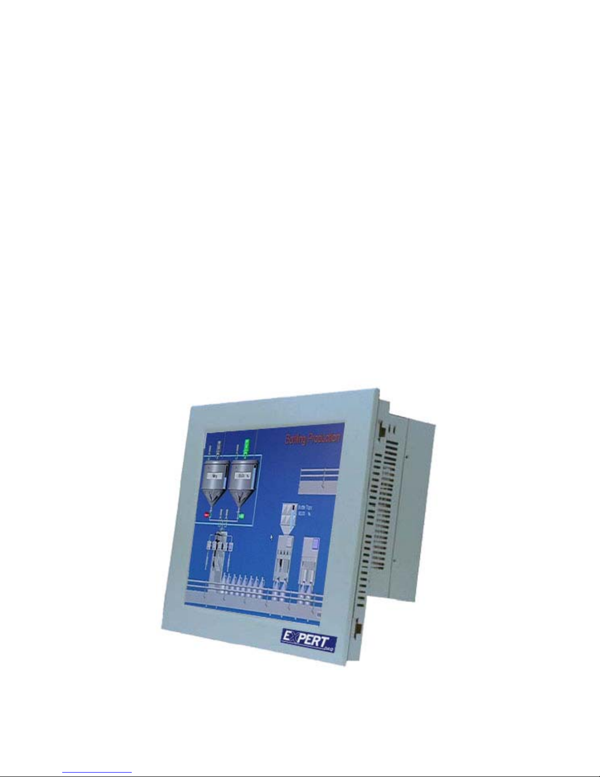
1.7 Brief Description of the EX-93211/93511/93711/93911
The EX-93211/93511/93711/93911 is a rugged and compact panel-mount industrial PC, which comes
with a 12-inch (luminance of 300 cd/m²)/15-inch (luminance of 400 cd/m²)/17-inch (luminance of 300
cd/m²)/19-inch (luminance of 250 cd/m²) TFT LCD. It is powered by an Intel Celeron 2.4GHz
processor/Intel Pentium 4 processor. The industrial panel PC also features one PCI expansion slot,
four COM ports, four USB 2.0 ports, one 40GB HDD, one CD-ROM, an ATX 12V power input. It is
ideal for use as a PC-based controller for Automotive, Logistic Process, Materials Handling, and Kiosk
applications.
Figure 1.5: Front View of EX-93211/93511/93711/93911
Page 15
EX-93211/93511/93711/93911User Manual
15
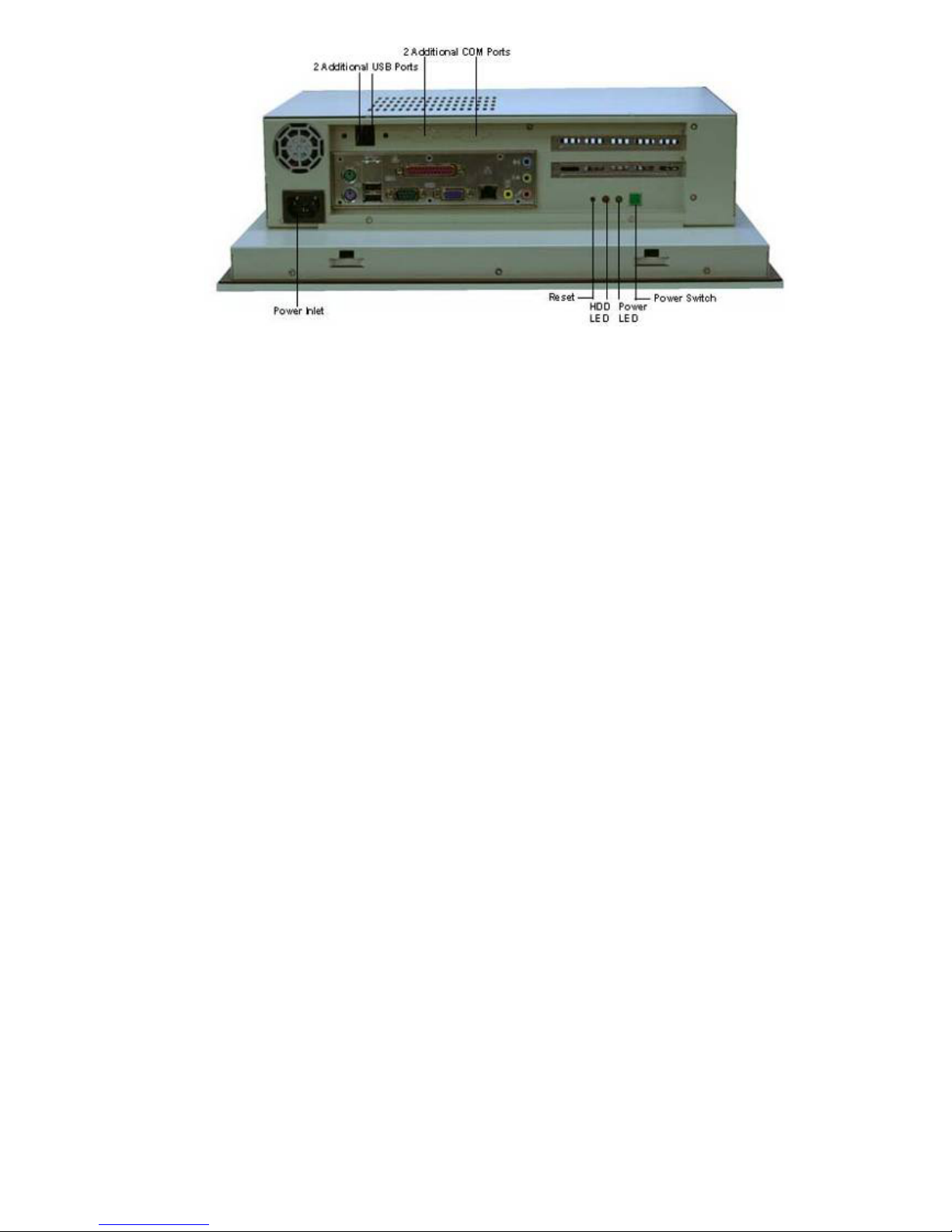
Figure 1.6: Rear View of EX-93211/93511/93711/93911
Page 16
EX-93211/93511/93711/93911User Manual
16
Chapter 2 Hardware
2.1 Mainboard
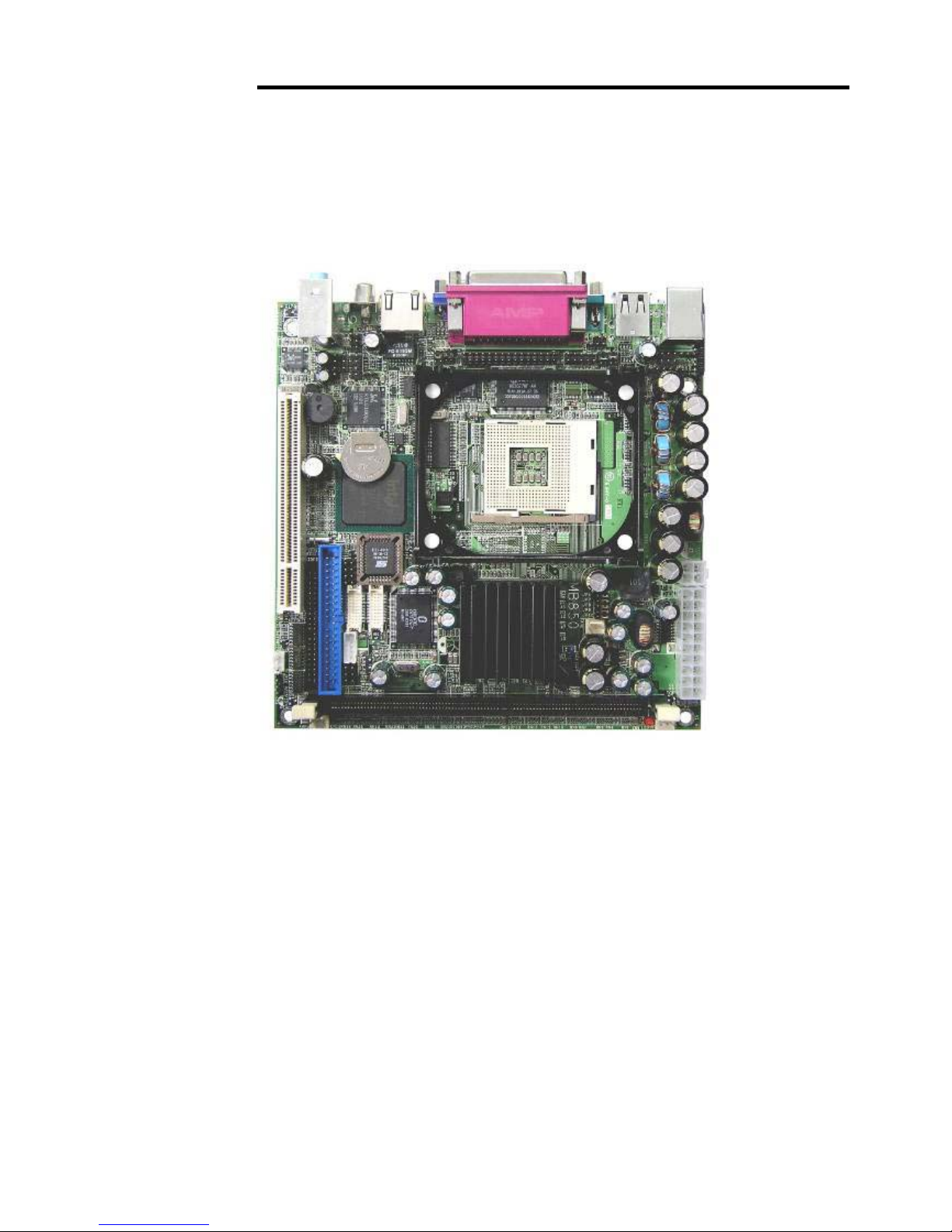
Figure 2.1: Mainboard Overview
Page 17
EX-93211/93511/93711/93911User Manual
17
2.2 Installations
This section provides information on how to use the jumpers and connectors on the mainboard in
order to set up a workable system.
2.2.1 Installing the CPU
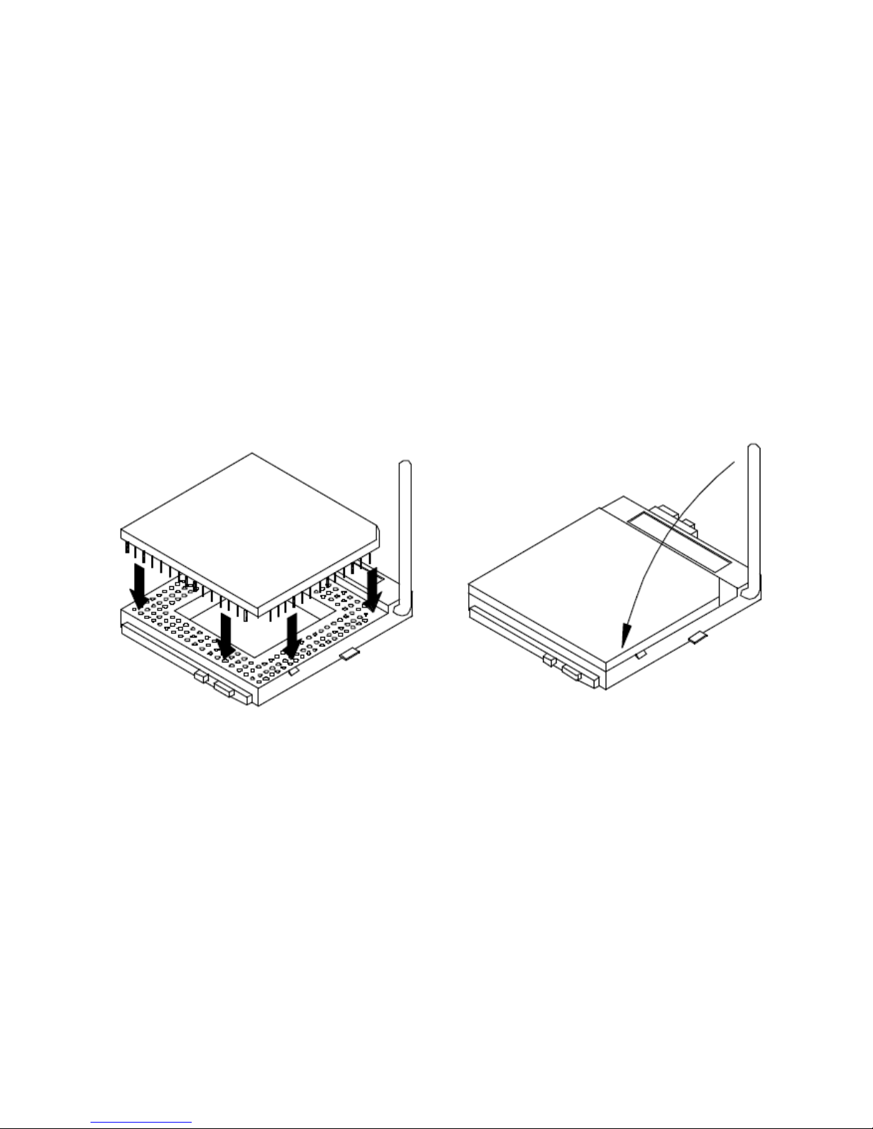
The mainboard supports a Socket 478 processor socket for Intel Pentium 4 processors or Pentium 4
Mobile processors. The Socket 478 processor socket comes with a lever to secure the processor.
Place the processor into the socket by making sure the notch on the corner of the CPU corresponds
with the notch on the inside of the socket. Once the processor slides into the socket, return the lever to
the lock position as shown in Figure 2.2. After you have installed the processor into the socket, check
if the jumpers for the CPU type and speed are correct.
Figure 2.2: Installation of CPU
Note:
Make sure the heat sink and the top surface of the CPU are in total contact to
avoid the overheating problem that would cause your system to hang or be unstable.
Page 18
EX-93211/93511/93711/93911User Manual
18
2.2.2 Installing the Memory
The mainboard supports one DDR memory socket for a maximum total memory of 1GB. The memory
module capacities supported are 128MB, 256MB, 512MB and 1GB. The following figure shows the
supported DDR DIMM configurations. The Intel 845GV supports configurations defined in the JEDEC
DDR DIMM specifications only. Non-JEDEC standard DIMMs such as double-sided x16 DDR SDRAM
DIMMs are not supported.
To install the DDR module, locate the DIMM slot on the embedded board and perform the following
steps:
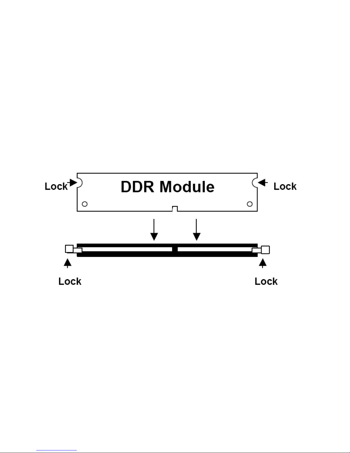
1. Hold the DDR module so that the key of the DDR module is aligned with those on the memory slot.
2. In an upright position, gently insert the DDR module into the DIMM slot until it is deeply sunk.
3. Lock the DDR module in place by pushing the levers on both sides of the module inward.
Figure 2.3: Installation of Memory Module
Page 19
EX-93211/93511/93711/93911User Manual
19
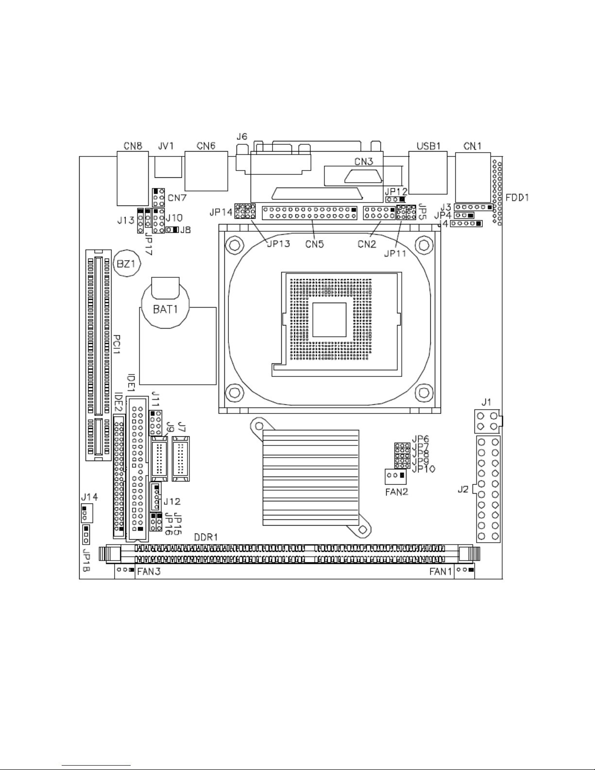
2.2.3 Installing the Jumpers
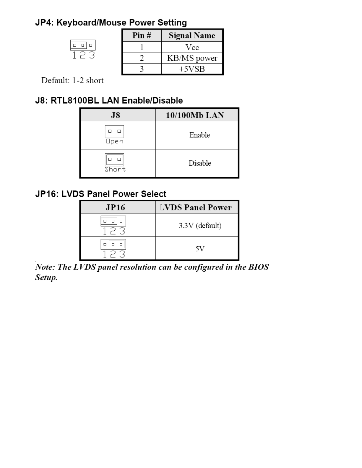
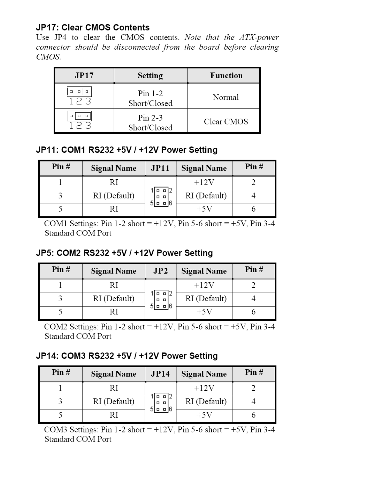
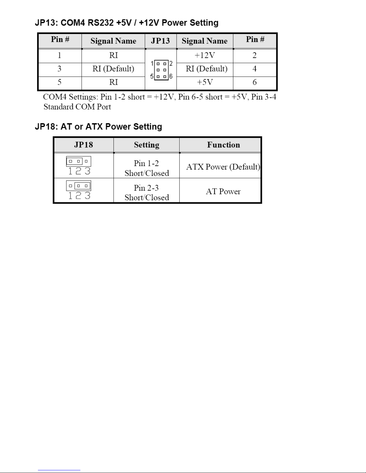
Jumpers are used on the mainboards to select various settings and features according to your needs
and applications. The following lists the connectors on the mainboard and their respective function.
Figure 2.4: Location of Jumpers
Page 20
EX-93211/93511/93711/93911User Manual
20
Page 21
EX-93211/93511/93711/93911User Manual
21
Page 22
EX-93211/93511/93711/93911User Manual
22
Page 23
EX-93211/93511/93711/93911User Manual
23
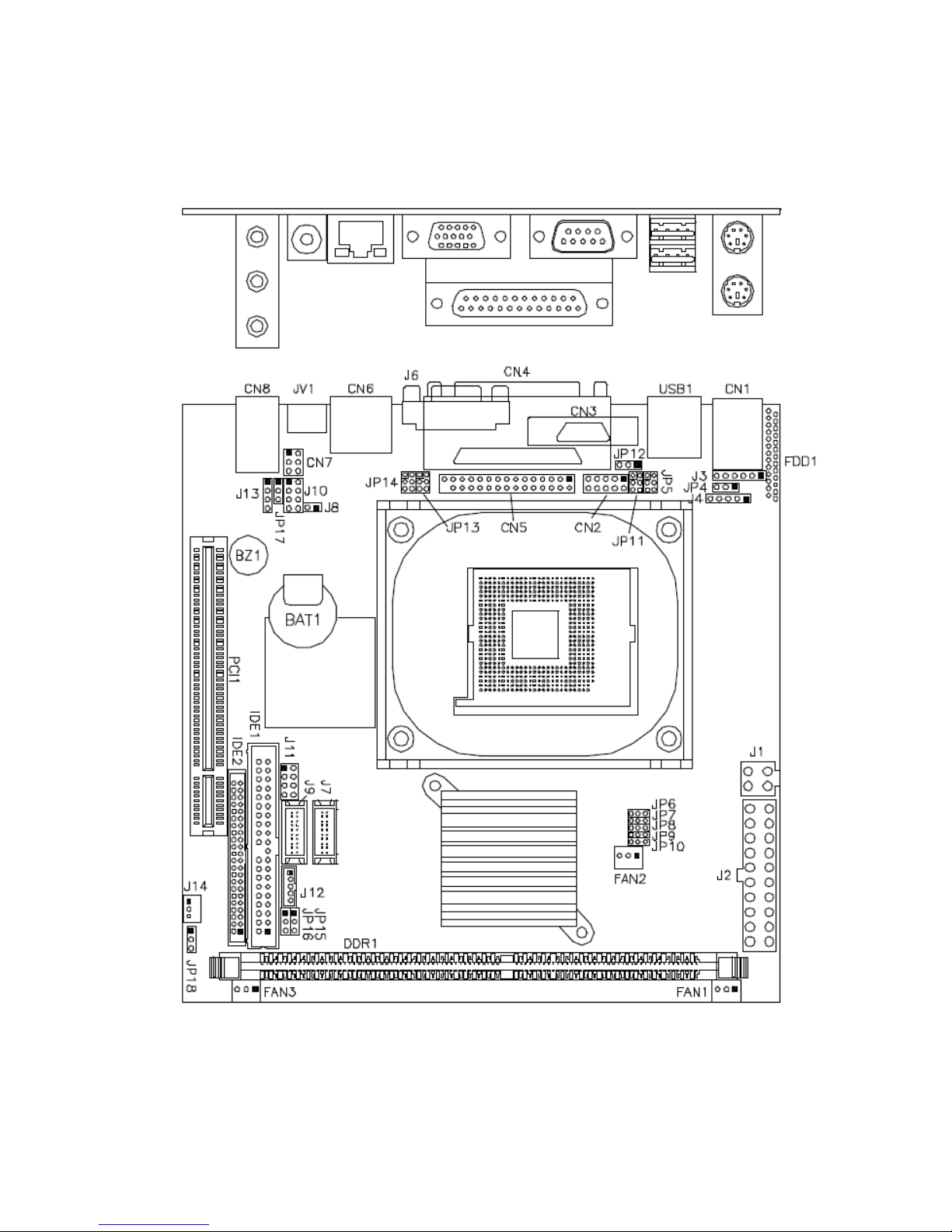
2.2.4 Connectors on the Mainboard
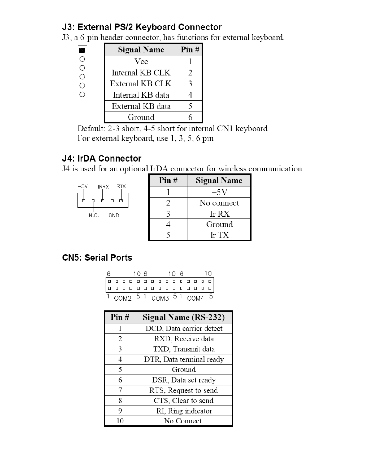
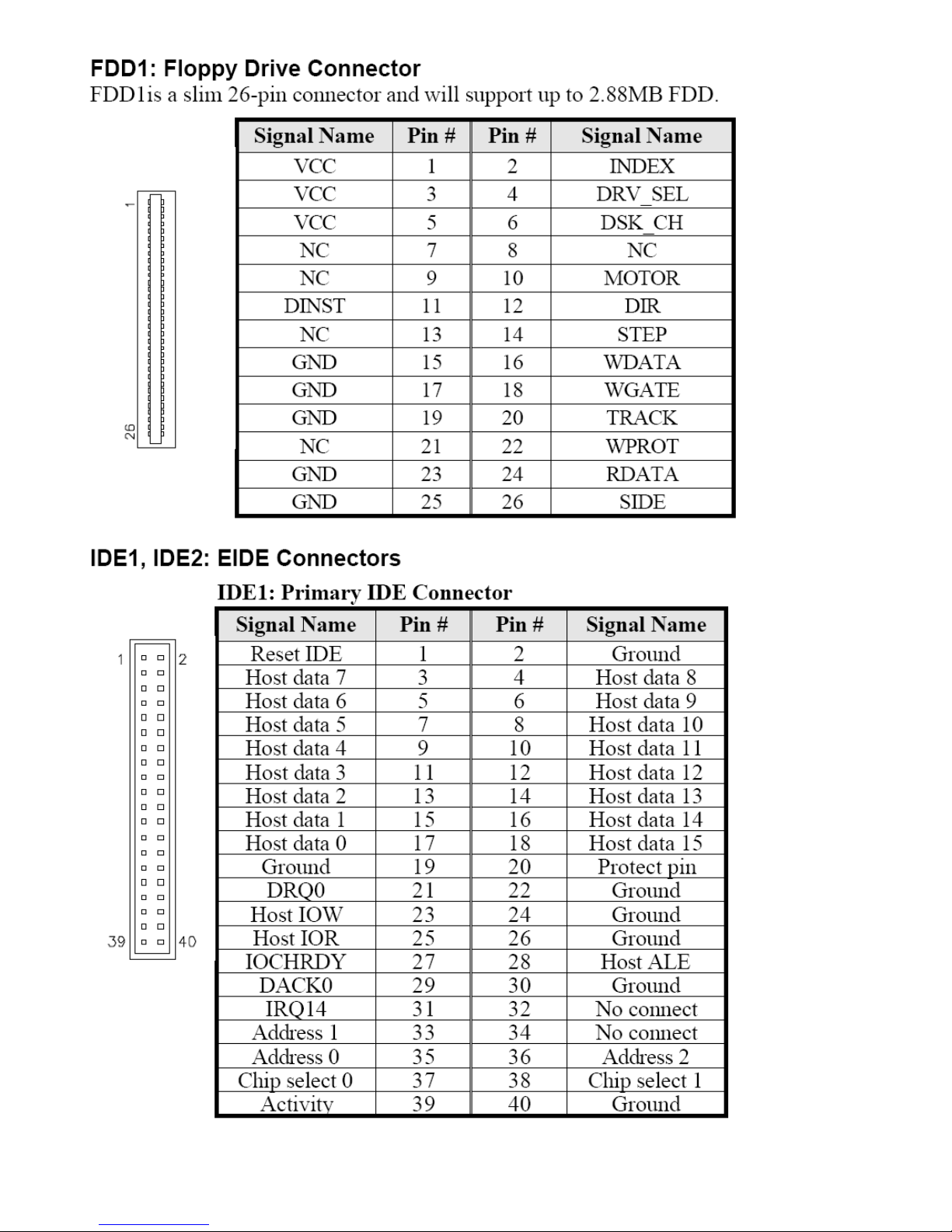
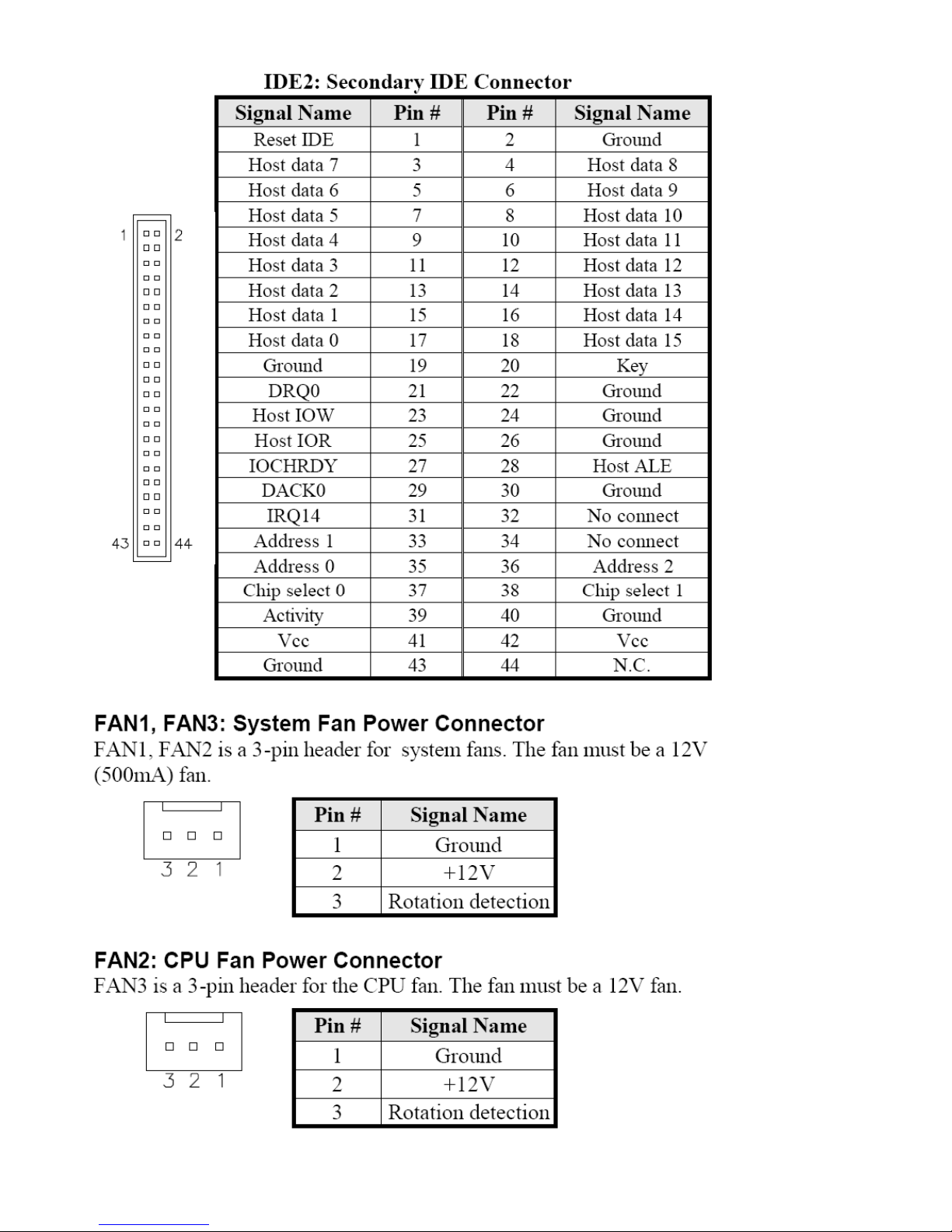
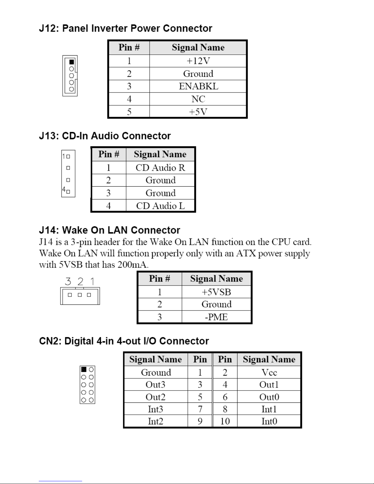
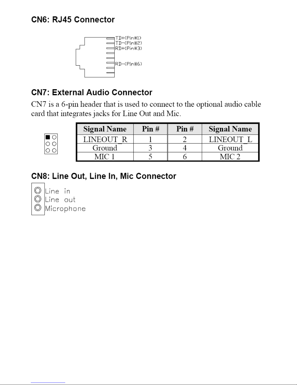
The connectors on the mainboard allows you to connect external devices, such as keyboard, floppy
disk drives, hard disk drives, printers, etc. the following table lists the connectors on the mainboard
and their respective functions
Figure 2.5: Location of Connectors
Page 24

EX-93211/93511/93711/93911User Manual
24
Page 25
EX-93211/93511/93711/93911User Manual
25
Page 26
EX-93211/93511/93711/93911User Manual
26
Page 27
EX-93211/93511/93711/93911User Manual
27
Page 28

EX-93211/93511/93711/93911User Manual
28
Page 29
EX-93211/93511/93711/93911User Manual
29
Page 30
EX-93211/93511/93711/93911User Manual
30
Page 31

EX-93211/93511/93711/93911User Manual
31
Chapter 3 BIOS Setup
3.1 BIOS Setup
This chapter describes the different settings available in the Award BIOS that comes with the board.
The items covered are as follows: BIOS Introduction, BIOS Setup, Standard CMOS Setup,
Advanced BIOS Features, Advanced Chipset Features, Integrated Peripherals, Power
Management Setup, PNP/PCI Configurations, PC Health Status, Frequency/Voltage Control,
Load Fail-Safe Defaults, Load Setup Defaults, Set Supervisor/User Password, Save & Exit
Setup, and Exit without Saving.
BIOS Introduction
The Award BIOS (Basic Input/Output System) installed in your computer system’s ROM supports Intel
processors. The BIOS provides critical low-level support for standards devices, such as disk drives,
serial ports and parallel ports. It also adds virus and password protection as well as special support for
fine-tuning the chipset controlling the entire system.
BIOS Setup
The Award BIOS provides a Setup utility program for sp ecifying the system configurations and settings.
The BIOS ROM of the system stores the Setup utility. When you on the computer, the Award BIOS is
immediately activated. Pressing the <Del> key immediately allows you to enter the Setup utility. If you
are a little bit late to press the <Del> key, POST (Power On Self Test) will continue with its test routines,
thus preventing you from invoking the Setup. If you still wish to enter Setup, restart the system by the
pressing the “Reset” button or simultaneously pressing the <Ctrl>, <Alt> and <Del> keys. You can
also restart by turning the system off and back on again. The following message will appear on the
screen:
Press <DEL> to Enter Setup
In general, you press the arrow keys to highlight items, <Enter> to select, the <PgUp> and <PgDn>
keys to change entries, <F1> for help and <Esc> to quit.
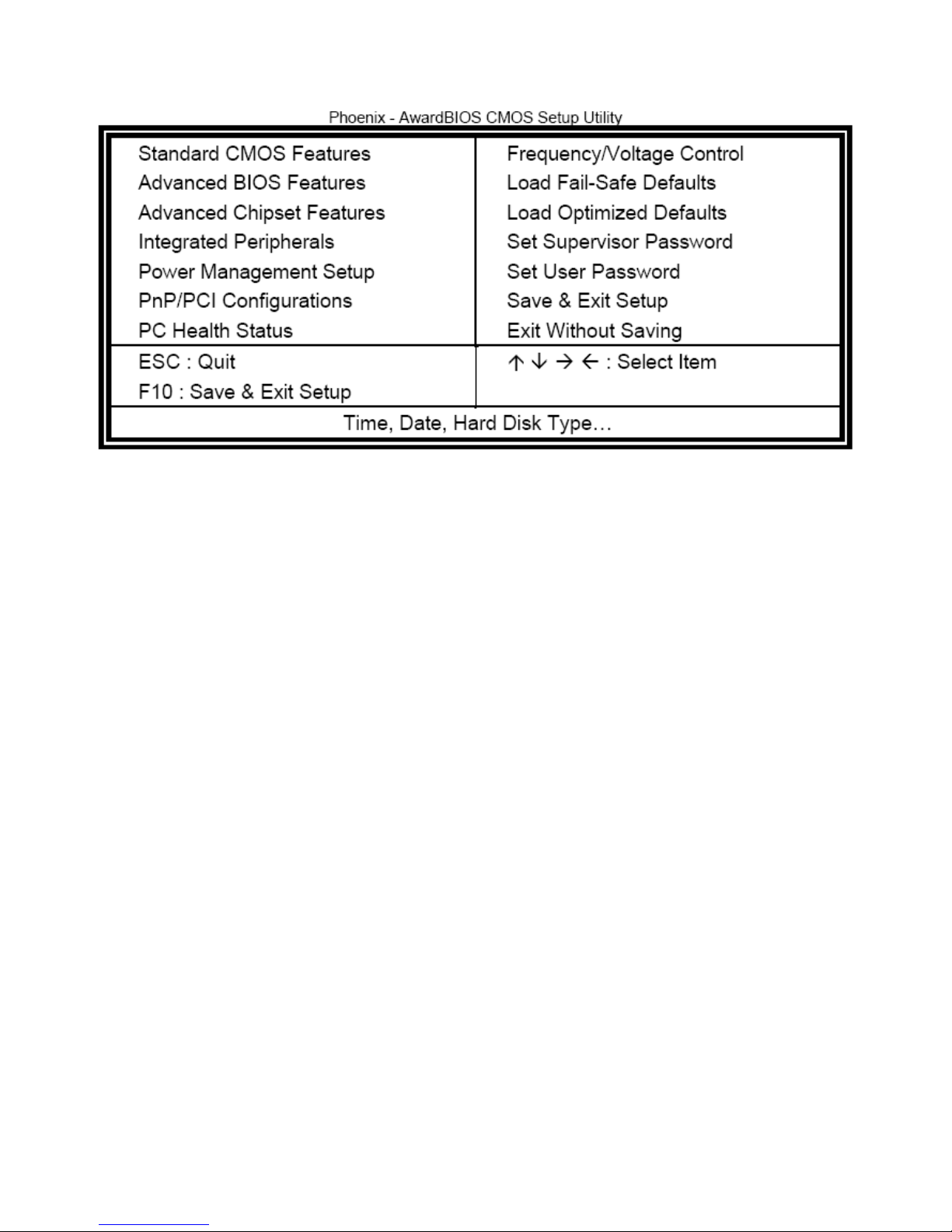
When you enter the Setup utility, the Main Menu screen will appear on the screen. The Main Menu
allows you to select from various Setup functions and exit choices.
Page 32
EX-93211/93511/93711/93911User Manual
32
The section below the Setup items of the Main Menu displays the control keys for this menu. At the
bottom of the Main Menu just below the control key section there is another section displaying
information on the currently-highlighted item in the list.
Note: If the system cannot boot after making and saving system changes with Setup, the Award
BIOS supports an override to the CMOS settings that reset your system to its default.
Warning: It is strongly recommended that you avoid making any changes to the chipset defaults.
These defaults have been carefully chosen by both Award and your system manufacturer
to provide the absolute maximum performance and reliability. Changing the defaults could
cause the system to become unstable and crash in some cases.
Page 33
EX-93211/93511/93711/93911User Manual
33
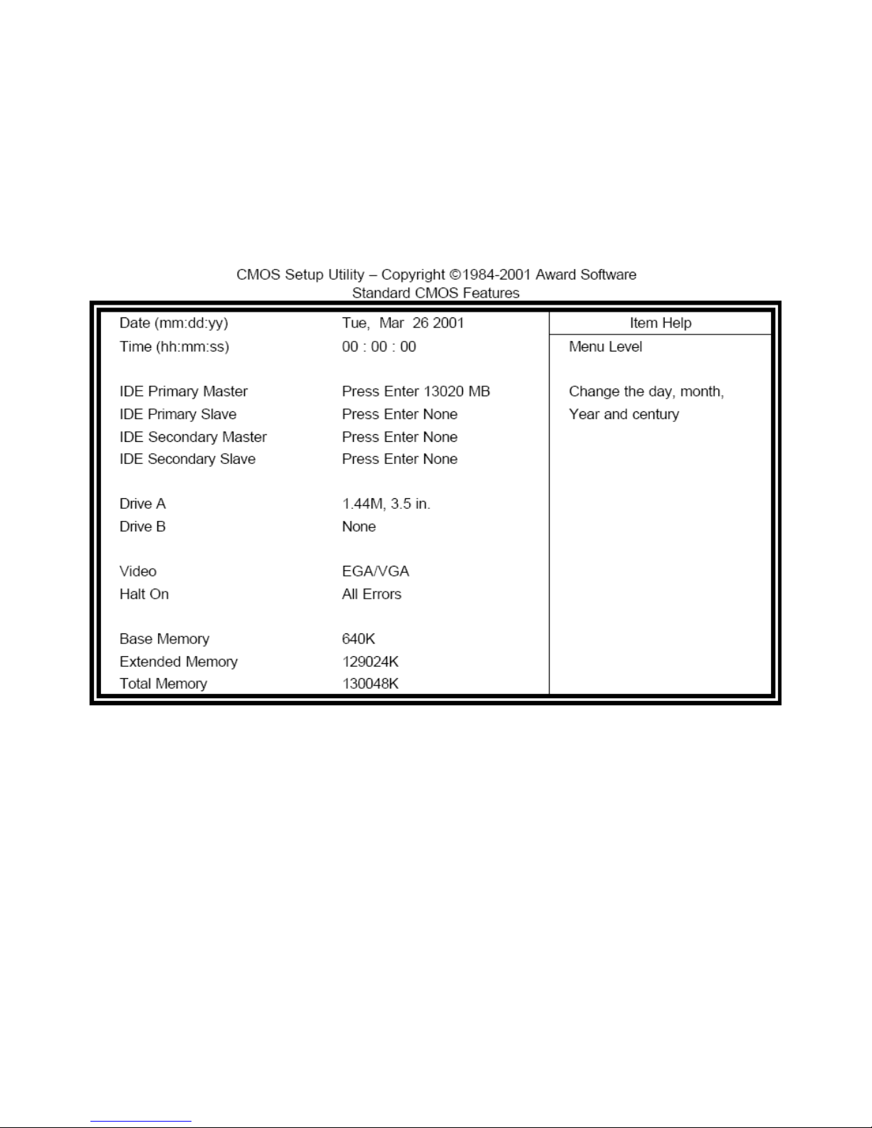
3.1.1 Standard CMOS Setup
“Standard CMOS Setup” choice allows you to record some basic hardware configurations in your
computer system and set the system clock and error handling. If the motherboard is already installed
in a working system, you will not need to select this option. You will need to run the Standard CMOS
option; however, if you change your system hardware configurations, the onboard battery fails, or the
configuration stored in the CMOS memory was lost or damaged.
At the bottom of the menu are the control keys for use on this menu. If you need any help in each item
field, you can press the <F1> key. It will display the relevant information to help you. The memory
display at the lower right-hand side of the menu is read-only. It will adjust automatically according to
the memory changed. The following describes each item of this menu:
Date
The date format is:
Day: Sun to Sat
Month: 1 to 12
Date: 1 to 31
Year: 1994 to 2079
Page 34

EX-93211/93511/93711/93911User Manual
34
To set the date, highlight the “Date” field and use the PageUp/PageDown or +/- keys to set the current
time.
Time
The time format is: Hour: 00 to 23
Minute: 00 to 59
Second: 00 to 59
To set the time, highlight the “Time” field and use the <PgUp>/<PgDn> or +/- keys to set the current
time.
IDE Primary HDDs/IDE Secondary HDDs
The onboard PCI IDE connectors provide Primary and Secondary channels for connecting up to four
IDE hard disks or other IDE devices. Each channel can support up to two hard disks; the first is the
“Master” while the second, the “Slave”.
Press <Enter> to configure the hard disk. The selections include Auto, Manual, and None. Select
“Manual” to define the drive information manually. You will be asked to enter the following items:
CYLS: Number of cylinders
HEAD: Number of read/write heads
PRECOMP: Write precompensation
LANDING ZONE: Landing zone
SECTOR: Number of sectors
The Access Mode selections are as follows:
Auto
Normal (HD<528MB)
Large (for MS-DOS only)
LBA (HD>528MB and supports Logical Block Addressing)
Drive/Drive B
These fields identify the types of floppy disk drive A or drive B that has been installed in the computer.
The available specifications are:
360KB 1.2MB 720KB 1.44MB 2.88MB
5.25 in 5.25 in 3.5 in 3.5 in 3.5 in
Video
This field selects the type of video display card installed in your system. You can choose the following
video display cards:
Page 35

EX-93211/93511/93711/93911User Manual
35
EGA/VGA for EGA, VGA, SEGA, SVGA
Or PGA monitor adapters (default)
CGA 40 Power up in 40 column mode
CGA 80 Power up in 80 column mode
MONO for Hercules or MDA adapters
Halt On
This field determines whether or not the system will halt if an error is detected during power up.
No errors The system boot will not be halted for any error
that may be detected.
All errors Whenever the BIOS detects a non-fatal error, the
system will stop and you will be prompted.
All, but Keyboard The system boot will not be halted for a keyboard
Error; it will stop for all other errors.
All, but Diskette The system boot will not be halted for a disk error; it
will stop for all other errors.
All, but Disk/Key The system boot will not be halted for a keyboard or
disk error; it will stip for all others.
Page 36
EX-93211/93511/93711/93911User Manual
36
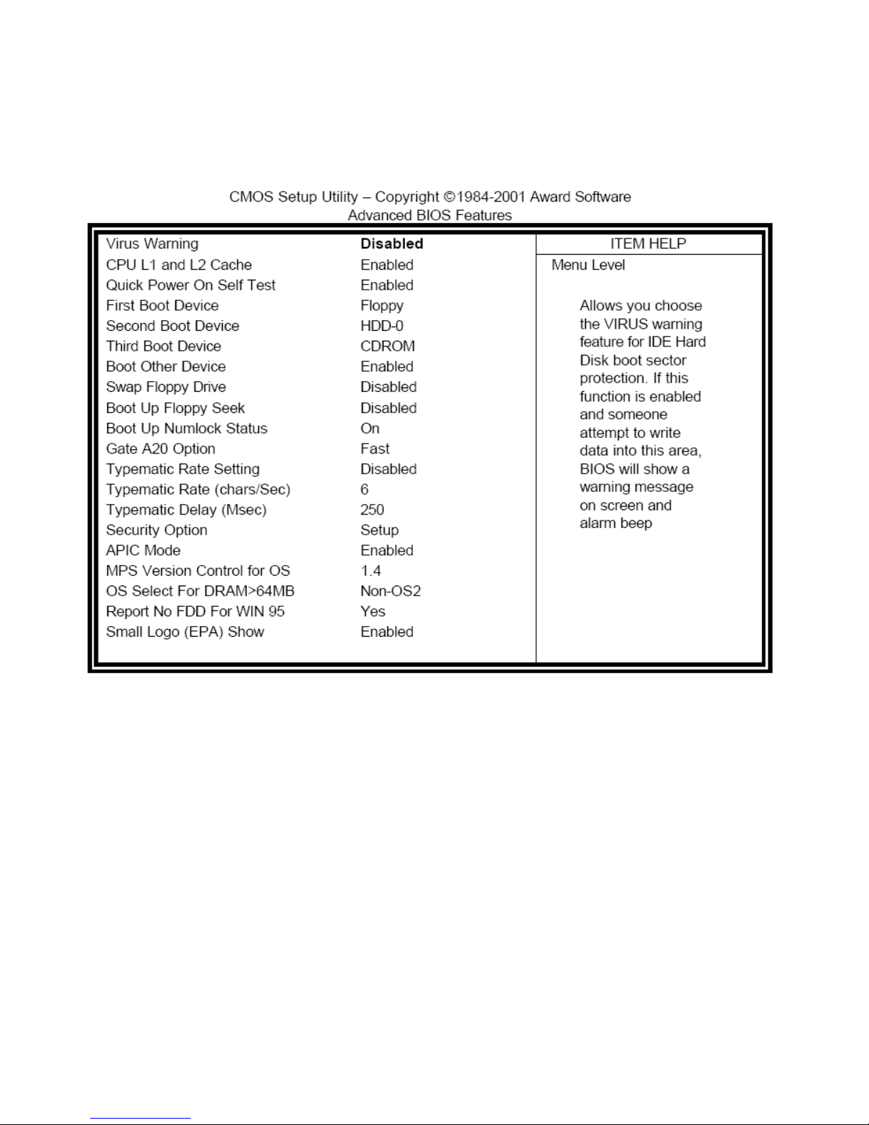
3.1.2 Advanced BIOS Features
This section allows you to configure and improve your system and allows you to set up some system
features according to your preference.
Virus Warning
This item protects the boot sector and partition table of your hard disk against accidental modifications.
If an attempt is made, the BIOS will halt the system and display a warning message. If this occurs, you
can either allow the operation to continue or run an anti-virus program to locate and remove the
problem.
CPU L1 and L2 Cache/CPU L3 Cache
Cache memory is additional memory that is much faster than conventional DRAM (system memory).
CPUs from the 486 type on contain internal cache memory, and most modern PCs have additional
(external) cache memory When the CPU request data, the system transfers the requested data from
the main DRAM into cache memory, for even faster access by the CPU. These items allow you to
enable (speed up memory access) or disable the cache function. By default, these items are Enabled.
Page 37

EX-93211/93511/93711/93911User Manual
37
Quick Power On Self Test
When enabled, this field speeds up the Power On Self Test (POST) after the system is turned on. If it
is set to Enabled, BIOS will skip some items.
First/Second/Third Boot Device
These fields determine the drive that the system searches first for an operating system. The options
available include Floppy, LS/ZIP, HDD-0, SCSI, CDROM, HDD-1, HDD-2, HDD-3, LAN and Disable.
Boot Other Device
These fields allow the system to search for an OS from other devices other than the ones selected in
the First/Second/Third Boot Device.
Swap Floppy Drive
This item allows you to determine whether or not to enable Swap Floppy Drive. When enabled, the
BIOS swaps floppy drive assignments so that Drive A becomes Drive B, and Drive B becomes Drive A.
By default, this field is set to Disabled.
Boot Up Floppy Seek
This feature controls whether the BIOS checks for a floppy drive while booting up. If it cannot detect
one (either due to improper configuration or its absence), it will flash an error message.
Boot Up NumLock Status
This allows you to activate the NumLock function after you power up the system.
Gate A20 Option
This field allows you to select how Gate A20 is worked. Gate A20 is a device used to address memory
above 1MB.
Typematic Rate Setting
When disabled, continually holding down a key on your keyboard will generate only one instance.
When enabled, you can set the two typematic controls listed next. By default, this field is set to
Disabled.
Typematic Rate (Chars/Sec)
When the typematic rate is enabled, the system registers repeated keystroke speeds. Settings are
from 6 to 30 characters per second.
Typematic Delay (Msec)
When the typematic rate is enabled, this item allows you to set the time interval for displaying the first
and second characters. By default, this item is set to 250msec.
Page 38

EX-93211/93511/93711/93911User Manual
38
Security Option
This field allows you to limit access to the System and Setup. The default value is Setup. When you
select System, the system prompts for the User Password every time you boot up. When you select
Setup, the system always boots up and prompts for the Supervisor Password only when the Setup
utility is called up.
APIC Mode
APIC stands for Advanced Programmable Interrupt Controller. The default setting is Enabled.
MPS Verson Control for OS
This option specifies the MPS (Multiprocessor Specification) version for your operating system. MPS
version 1.4 added extended configuration tables to improve support for multiple PCI bus
configurations and improve future expandability.
OS Select for DRAM >64MB
This option allows the system to access greater than 64MB of DRAM memory when used with OS/2
That has to depend on certain BIOS calls to access memory. The default setting is Non-OS/2.
Report No FDD for WIN 95
If you are using Windows 95/98 without a floppy disk drive, select Enabled to release IRQ6. This is
required to pass Windows 95/98’s SCT test. You should also disable the Onboard FDC Controller in
the Integrated Peripherals screen when there is no floppy drive in the system. If you set this feature to
Disabled, the BIOS will not report the missing floppy drive to Win95/98.
Small Logo (EPA) Show
The EPA logo appears at the right side of the monitor screen when the system is boot up. The default
setting is Enabled.
Page 39
EX-93211/93511/93711/93911User Manual
39
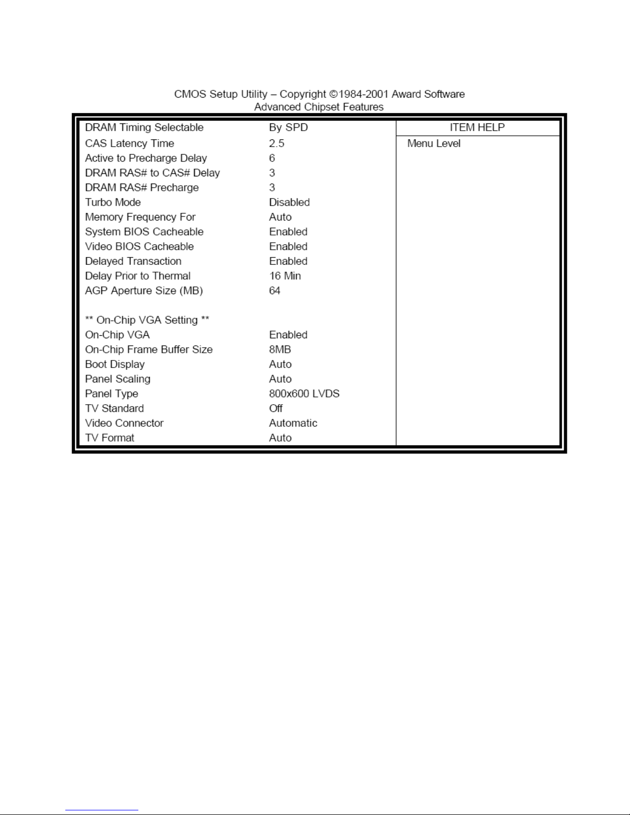
3.1.3 Advanced Chipset Features
This Setup menu controls the configuration of the chipset.
DRAM Timing Selectable
This option refers to the method by which the DRAM timing is selected. The default is By SPD.
CAS Latency Time
You can select CAS latency time in HCLKs of 2/2 or 2.5 or 3/3. The system board designer should set
the values in this field, depending on the DRAM installed. Do not change the values in this field unless
you change specifications of the installed DRAM or the installed CPU. The choices are 2 and 3.
Active to Precharge Delay
The default setting for the Active to Precharge Delay is 6.
DRAM RAS# to CAS# Delay
This option allows you to insert a delay between the RAS (Row Address Strobe) and CAS (Column
Address Strobe) signals. This delay occurs when the SDRAM is written to, read from or refreshed.
Reducing the delay improves the performance of the SDRAM.
Page 40

EX-93211/93511/93711/93911User Manual
40
DRAM RAS# Precharge
This option sets the number of cycles required for the RAS to accumulate its charge before the
SDRAM refreshes. The default setting for the Active to Precharge Delay is 3.
Memory Frequency For
This field sets the frequency of the DRAM memory installed. The default setting is Auto. The other
settings are DDR200 and DDR266.
System BIOS Cacheable
The setting of Enabled allows caching of the system BIOS ROM at F000h-FFFFFh, resulting in better
system performance. However, if any program writes to this memory area, a system error may result.
Video BIOS Cacheable
The Enabled setting allows caching of the video BIOS ROM at C0000h-F7FFFh, resulting in better
video performance. However, if any program writes to this memory area, a system error may result.
Delayed Transaction
The chipset has an embedded 32-bit posted write buffer to support delay transactions cycles. Select
Enabled to support compliance with PCI specification version 2.1.
Delay Prior to Thermal
This field activates the CPU thermal function after the system boots for the set number of minutes. The
options are 16 min or 64 min.
AGP Aperture Size
The field sets aperture size of the graphics. The aperture is a portion of the PCI memory address
range dedicated for graphics memory address space. Host cycles that hit the aperture range are
forwarded to the AGP without any translation. The default setting is 64M.
On-Chip VGA
By default, the On-Chip VGA or chipset-integrated VGA is Enabled.
On-Chip Frame Buffer Size
The On-Chip Frame Buffer Size can be set to 1MB or 8MB. This memory is shared with the system
memory.
Boot Display
Boot Display determines the display output device where the system boots. The options are Auto,
CRT and TV.
Panel Scaling
Setting this field to choose the initial state of Panel Fitting. A new state will overwrite the initial state
Page 41

EX-93211/93511/93711/93911User Manual
41
and be remembered if Panel Fitting HotKey is requested. Panel Fitting can only be enabled when in
LFP only display. This panel fitting state is checked to update the hardware status after changing
Video mode or Switching Display Devices.
Panel Type
This field sets panel type with the resolution and interface information. The default setting is 800x600
LVDS.
TV Standard
This field sets the TV Standard as NTSC, PAL, SECAM or can be set OFF. The default setting is Off.
Video Connector
The default setting is Automatic.
TV Format
The default setting is Auto.
Page 42
EX-93211/93511/93711/93911User Manual
42
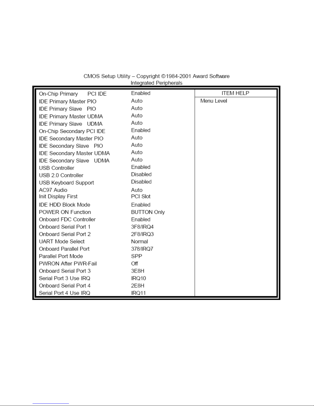
Integrated Peripherals
This section sets configurations for your hard disk and other integrated peripherals. The first screen
shows three main items for user to select. Once an item is selected, a submenu appears. Details
follow.
OnChip Primary/Secondary PCI IDE
The integrated peripheral controller contains an IDE interface with support for two IDE channels.
Select Enabled to activate each channel separately.
IDE Primary/Secondary Master/Slave PIO
These fields allow your system hard disk controller to work faster. Rather than have the BIOS issue a
Page 43

EX-93211/93511/93711/93911User Manual
43
series of commands that transfer to or from the disk drive, PIO (Programmed Input/Output) allows the
BIOS to communicate with the controller and CPU directly.
The system supports five modes, numbered from 0 (default) to 4, which primarily differ in timing. When
Auto is selected, the BIOS will select the best available mode.
IDE Primary/Secondary Master/Slave UDMA
These fields allow your system to improve disk I/O throughput to 33Mb/sec with the Ultra DMA/33
feature. The options are Auto and Disabled.
USB Controller
The options for this field are Enabled and Disabled. By default, this field is set to Enabled.
USB 2.0 Controller
The options for this field are Enabled and Disabled. By default, this field is set to Disabled. In order to
use USB 2.0, necessary OS drivers must be installed first.
USB Keyboard Support
The options for this field are Enabled and Disabled. By default, this field is set to Disabled.
AC97 Audio
The default setting is Auto.
Init Display First
This field allows the system to initialize first the VGA card on chip or the display on the PCI slot. By
default, the PCI slot is initialized first.
IDE HDD Block Mode
This field allows your hard disk controller to use the fast block mode to transfer data to and from your
hard disk drive.
Power On Function
This field shows how the system can be powered on from the Off state. The default setting is Button
Only.
Onboard FDC Controller
Select Enabled if your system has a floppy disk controller (FDC) installed on the motherboard and you
wish to use it. If you install an add-in FDC or the system has no floppy drive, select Disabled in this
field. This option allows you to select the onboard FDD port.
Page 44

EX-93211/93511/93711/93911User Manual
44
Onboard Serial/Parallel Port
These fields allow you to select the onboard serial and parallel ports and their addresses. The default
values for these ports are:
Serial Port 1 3F8/IRQ4
Serial Port 2 2F8/IRQ3
Serial Port 3 3E8H/IRQ10
Serial Port 4 2E8H/IRQ11
Parallel Port 378H/IRQ7
UART Mode Select
This field determines the UART 2 mode in your computer. The default value is Normal. Other options
include IrDA and ASKIR.
Parallel Port Mode
This field allows you to determine parallel port mode function
SPP Standard Printer Port
EPP Enhanced Parallel Port
ECP Extended Capabilities Port
PWRON After PWR-Fail
This field sets the system power status whether on or off when power returns from a power failure
situation.
Page 45
EX-93211/93511/93711/93911User Manual
45
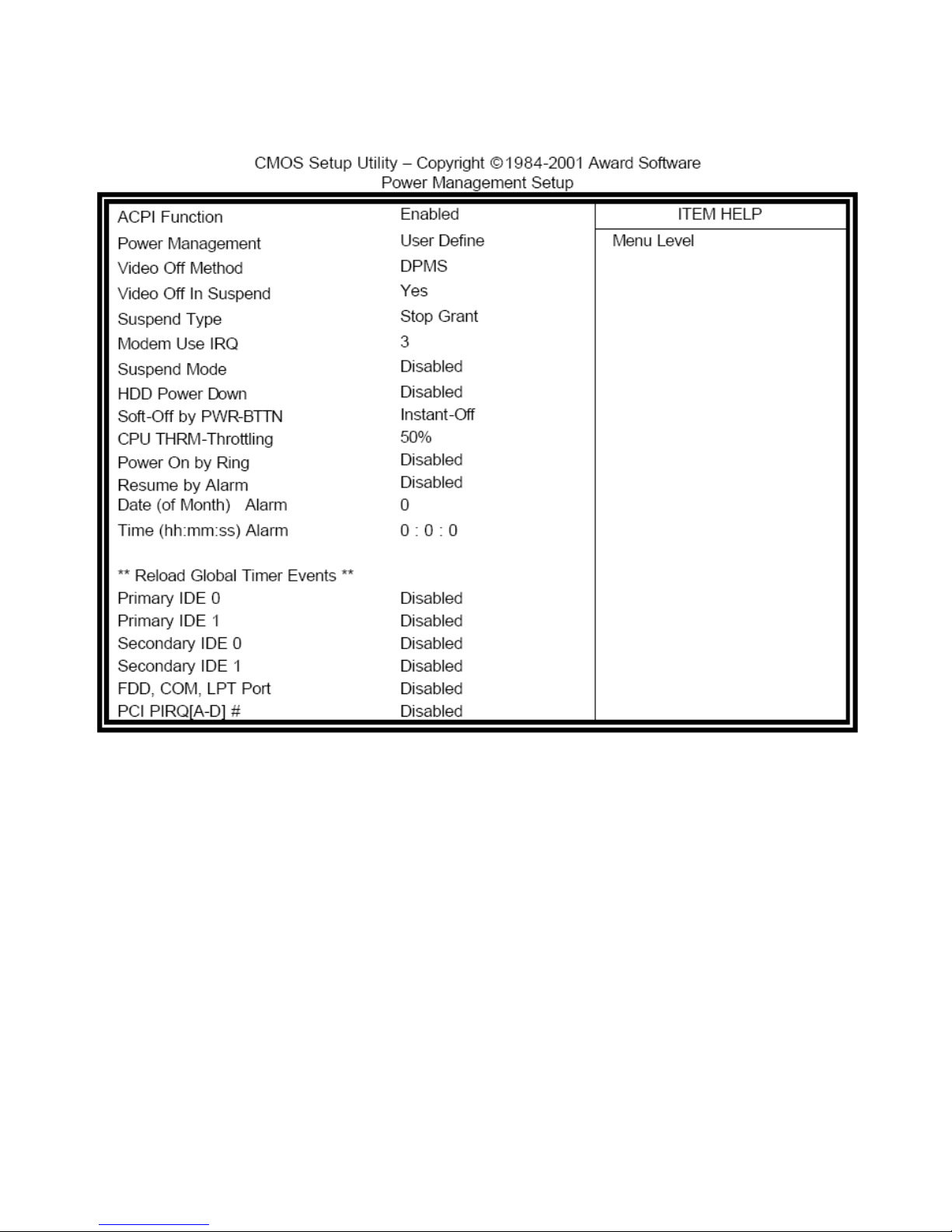
3.1.4 Power Management Setup
The Power Management Setup allows you to save energy of your system effectively.
ACPI Function
Enable this function to support ACPI (Advance Configuration and Power Interface).
Power Management
This field allows you to select the type of power saving management modes. There are four selections
for Power Management.
Min. Power Saving Minimum power management
Max. Power Saving Maximum power management
User Define Each of the ranges is from 1min to 1hr. Except for HDD Power
Down which ranges from 1 min to 15 min.
Page 46

EX-93211/93511/93711/93911User Manual
46
Video Off Method
This field defines the Video Off features. There are three options.
V/H SYNC + Blank Default setting, blank the screen and turn off
Vertical and horizontal scanning
DPMS Allows BIOS to control the video display.
Blank Screen Writes blanks to the video buffer
Video Off In Suspend
When enabled, the video is off in suspend mode. The default setting is Yes.
Suspend Type
The default setting for the Suspend Type field is Stop Grant.
Modem Use IRQ
This field sets the IRQ used by the Modem. By default, the setting is 3.
Suspend Mode
When enabled, and after the set time of system inactivity, all devices except the CPU will be shut off.
HDD Power Down
When enabled, and after the set time of system inactivity, the hard disk drive will be powered down
while all other devices remain active.
Soft-Off by PWRBTN
This field defines the power-off mode when using an ATX power supply. The Instant Off mode allows
powering off immediately upon pressing the power button. In the Delay 4 Sec mode, the system
powers off when the power button is pressed for more than four seconds or enters the suspend mode
when pressed for less than 4 seconds.
CPU THRM-Throttling
When the system enters Doze mode, the CPU clock runs only part of the time. You may select the
percent of time that the clock runs.
Power On by Ring
This field enables or disables the power on of the system through the modem connected to the serial
port or LAN.
Resume by Alarm
This field enables or disables the resumption of the system operation. When enabled, the user is
allowed to set the Date and Time.
Page 47
EX-93211/93511/93711/93911User Manual
47
Reload Global Timer Events
The HDD, FDD, COM, LPT ports and PCI PIRQ are I/O events that can prevent the system from
entering a power saving mode or can awaken the system from such a mode. When an I/O device
wants to gain the attention of the operating system, it signals this by causing an IRQ to occur. When
the operating system is ready to respond to the request, it interrupts itself and performs the service.
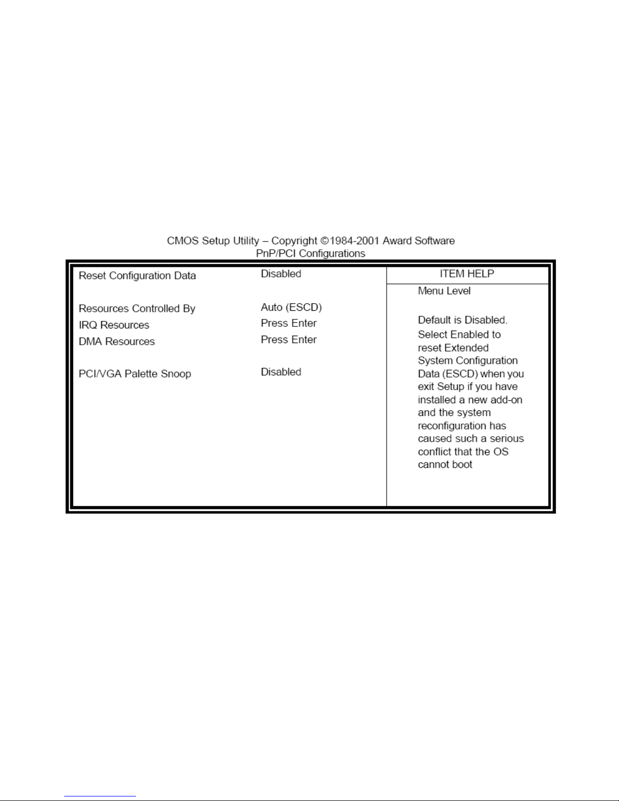
3.1.5 PnP/PCI Configurations
This option configures the PCI bus system. All PCI bus systems on the system use INT#, thus all
installed PCI cards must be set to this value.
Reset Configuration Data
This field allows you to determine whether to reset the configuration data or not. The default value is
Disabled.
Resources Controlled by
This PnP BIOS can configure all of the boot and compatible devices automatically with the use of an
PnP operating system such as Windows 95.
PCI/VGA Palette Snoop
Some non-standard VGA display cards may not show colors properly. This field allows you to set
whether or not MPEG ISA/VESA VGA cards can work with PCI/VGA. When this field is enabled, a
PCI/VGA can work with PCI/VGA. When this field is enabled, a PCI/VGA can work with an MPEG
Page 48
EX-93211/93511/93711/93911User Manual
48
ISA/VESA VGA card. When this field is disabled, a PCI/VGA cannot work with an MPEG/VESA card.
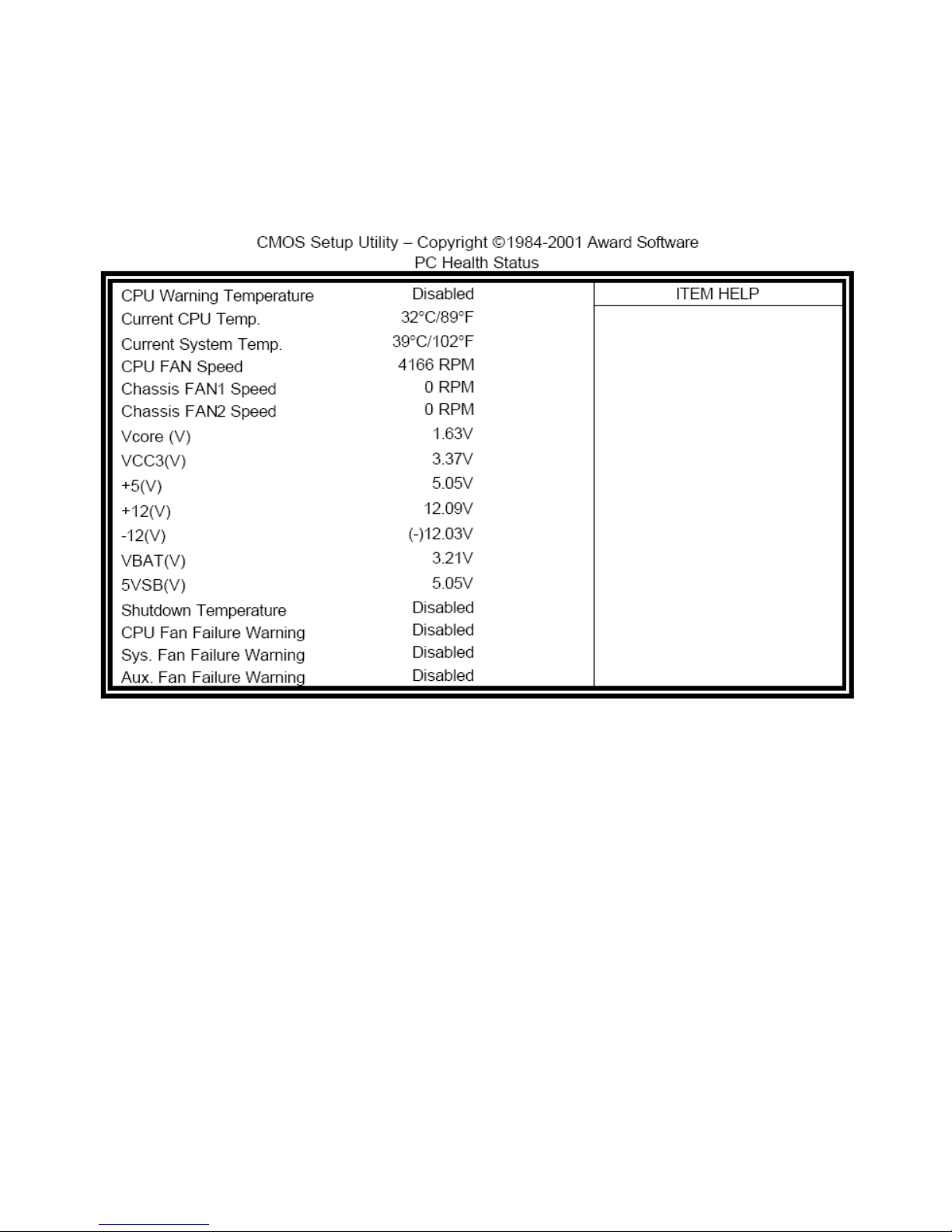
3.1.6 PC Health Status
This section shows the parameters in determining the PC Health Status. These parameters include
temperatures, fan speeds and voltages.
3.1.7 Load Fail-Safe Defaults
This option allows you to load the troubleshooting default values permanently stored in the BIOS ROM.
These default settings are non-optimal and disable all high-performance features.
3.1.8 Load Optimized Defaults
This option allows you to load the default values to your system configuration. These default settings
are optimal and enable all high performance features.
3.1.9 Set Supervisor Password
These two options set the system password. Supervisor Password sets a password that will be used
to protect the system and Setup utility. User Password sets a password that will be used exclusively
Page 49

EX-93211/93511/93711/93911User Manual
49
on the system. To specify a password, highlight the type you want and press <Enter>. The Enter
password: message prompts on the screen. Type the password, up to eight characters in length, and
press <Enter>. The system confirms your password by asking you to type it again. After setting a
password, the screen automatically returns to the main screen.
To disable a password, just press the <Enter> key when you are prompted to enter the password. A
message will confirm the password to be disabled. Once the password is disabled, the system will
boot and you can enter Setup freely.
3.1.10 Save & Exit Setup
This option allows you to determine whether or not to accept the modifications. If you type “Y”, you will
quit the Setup utility and save all changes into the CMOS memory. If you type “N”, you will return to
Setup utility.
3.1.11 Exit without Saving
Select this option to exit the Setup utility without saving the changes you have made in this section.
Typing “Y” will quit the Setup utility without saving the modifications. Typing “N” will return you to Setup
utility.
Page 50

EX-93211/93511/93711/93911User Manual
50
Chapter 4 Installation of Drivers
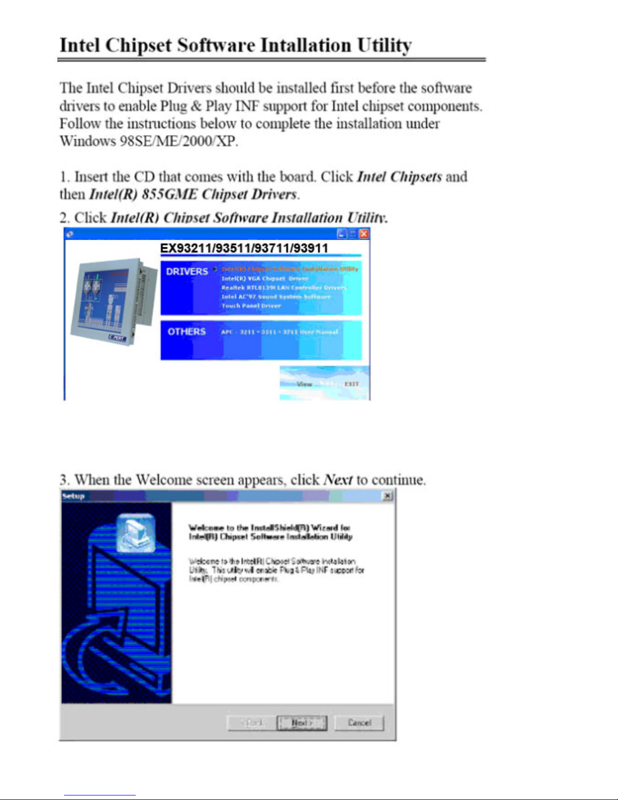
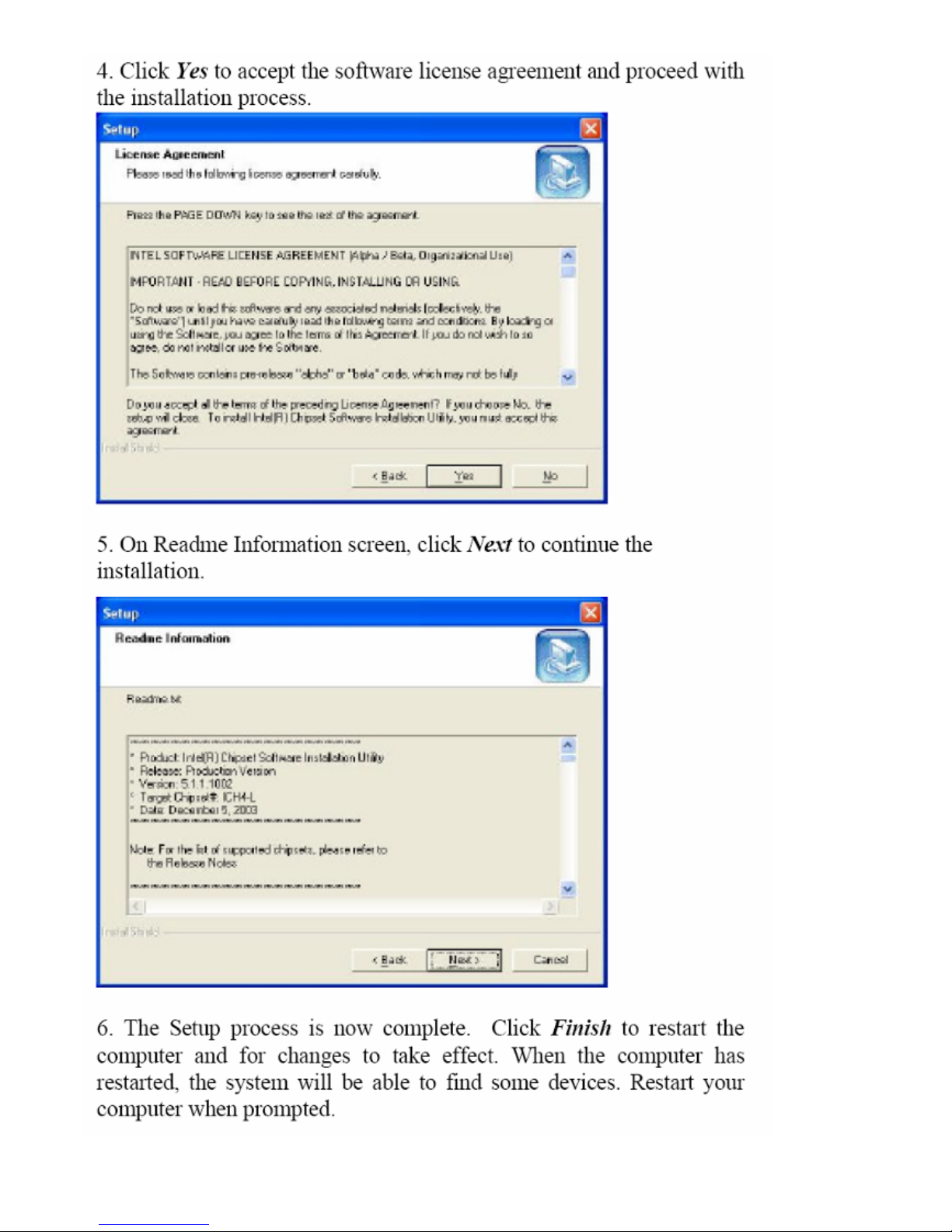
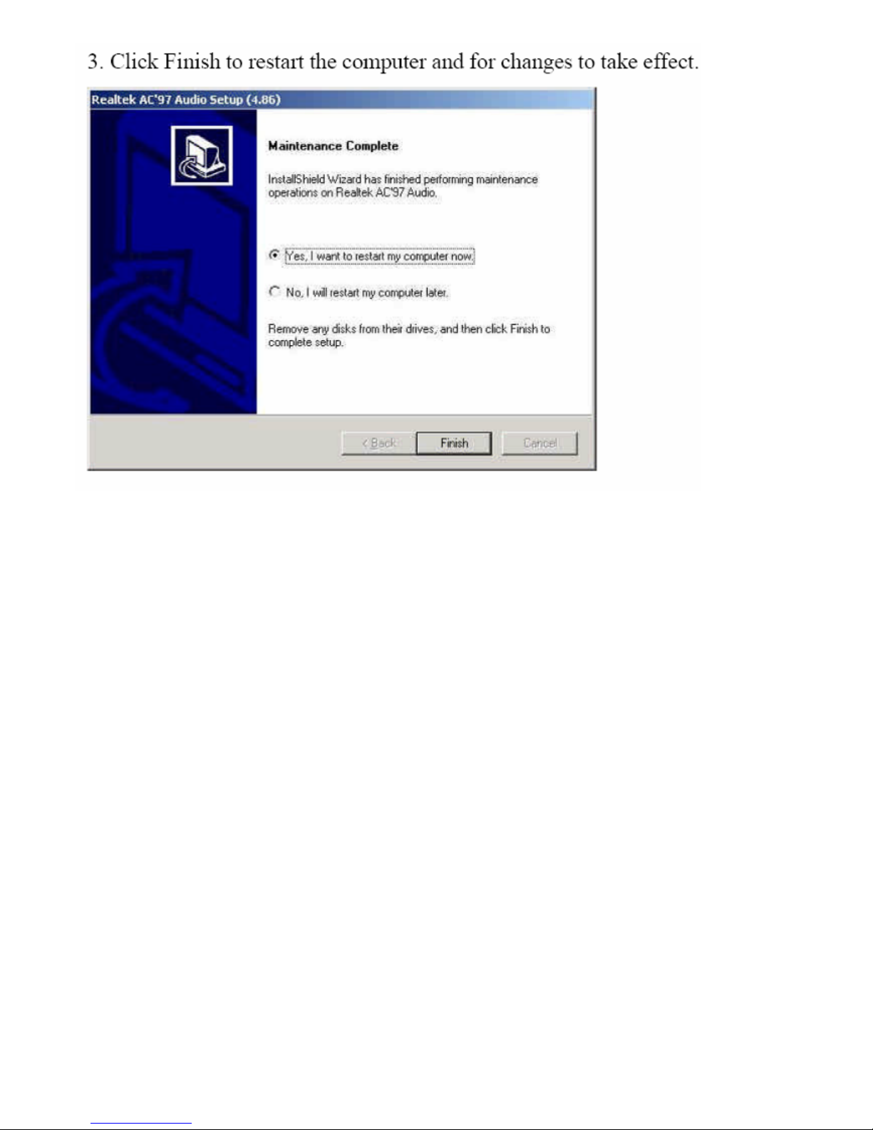
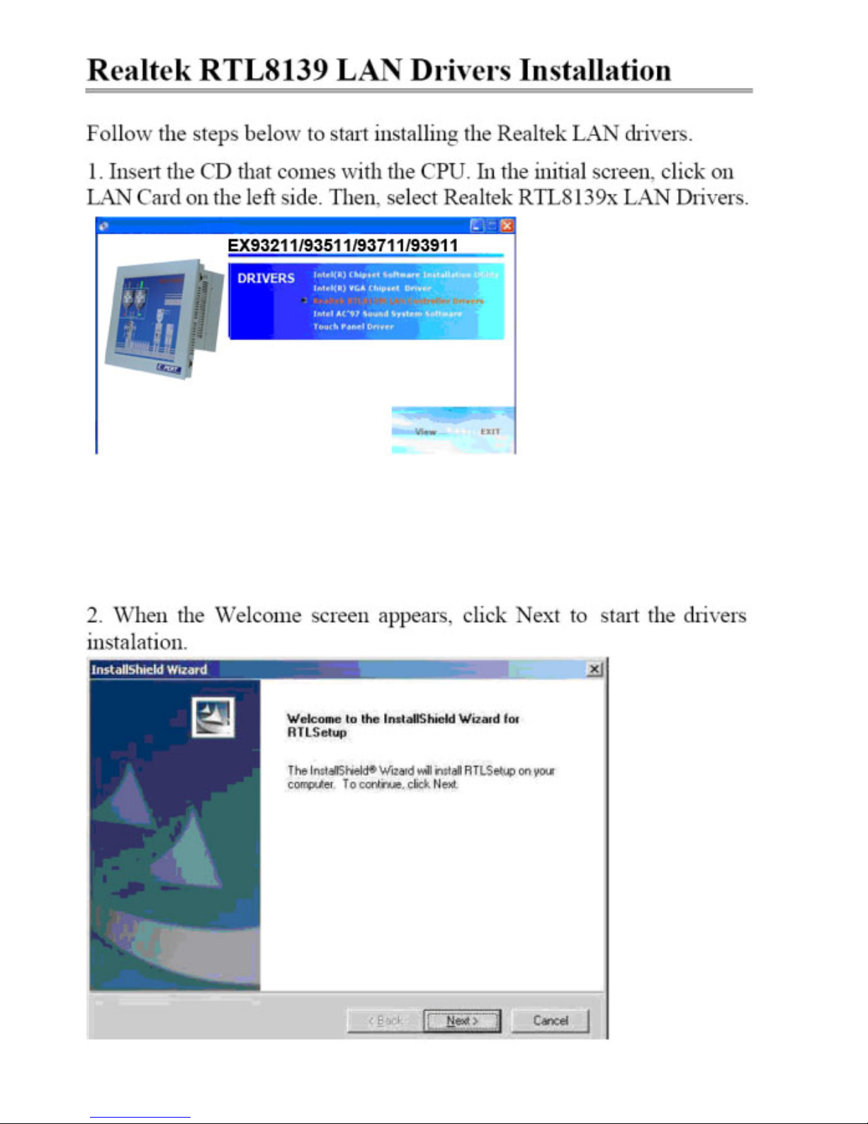
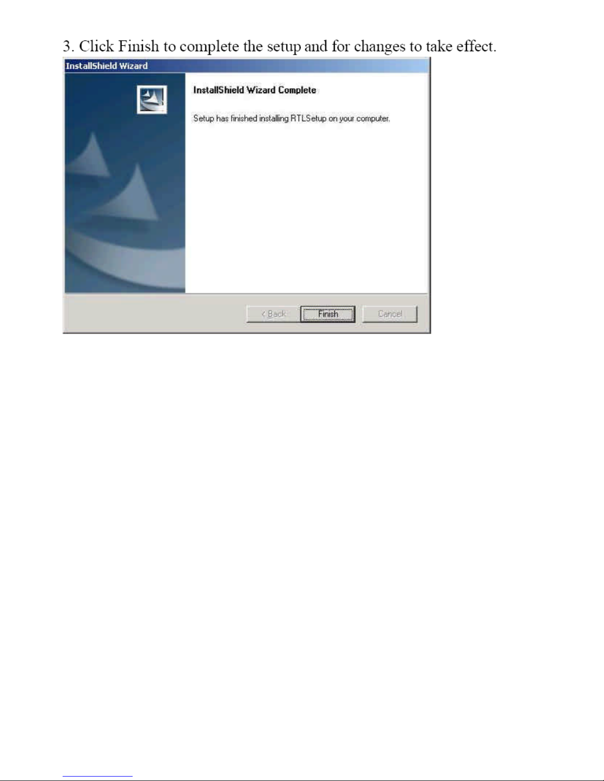
This chapter describes the installation procedures for software and drivers under the Windows 98,
Windows NT4.0, Windows 2000. The software and drivers are included with the motherboard. The
contents include Intel Chipset Software Installation Utility, Intel 845GV Chipset Graphics Driver
Installation, Realtek AC97 Codec Audio Driver Installation, and Realtek RTL8100 LAN Drivers
Installation.
I
Important Note:
After installing your Windows operating system (Windows
98/98SE/ME/2000/XP), you must install first the Intel Chipset Software
Installation Utility before proceeding with the installation of drivers.
Page 51
EX-93211/93511/93711/93911User Manual
51
Page 52
EX-93211/93511/93711/93911User Manual
52
Page 53

EX-93211/93511/93711/93911User Manual
53
Page 54
EX-93211/93511/93711/93911User Manual
54
Page 55
EX-93211/93511/93711/93911User Manual
55
Page 56
EX-93211/93511/93711/93911User Manual
56
Page 57
EX-93211/93511/93711/93911User Manual
57
Page 58
EX-93211/93511/93711/93911User Manual
58
Page 59
EX-93211/93511/93711/93911User Manual
59
Page 60
EX-93211/93511/93711/93911User Manual
60
Page 61
EX-93211/93511/93711/93911User Manual
61
Chapter 5 Touch Screen Installation
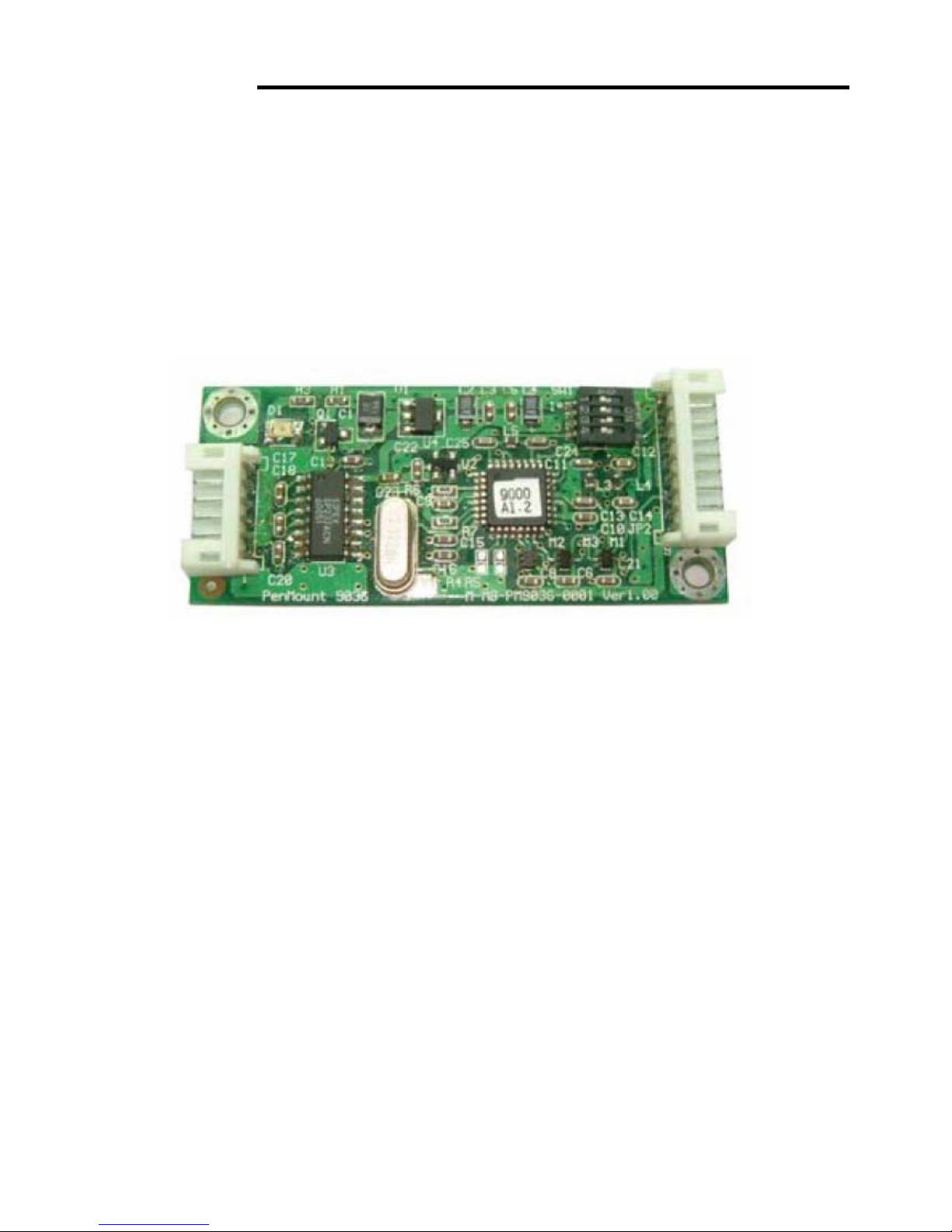
5.1 Introduction to Touch Screen Controller Board
The control board is configured for use with the RS-232 interface. It connects to the touch screen,
power supply and computer system’s RS-232 port, and supports 4-, 5- and 8-wire touch screens. The
control board has some advanced functions, such as PnP and non-PnP mode adjustable baud rate,
thus making easy for customers to select different touch screens without changing the control board.
The size of the board is 25 by 60mm, and it has two connectors and one dipswitch on-board.
Figure 5.1: Bird’s Eye View of Control Board
5.2 Windows 2000/XP Driver Installation for Control Board
Before installing the Windows 2000/XP driver software, you must have the Windows
2000/XP system installed and running on your computer. You must also have the 9036
PenMount Serial Interface controller board installed. Contents of the PenMount
Windows 2000/XP driver folder are listed below:
DMC9000.inf
DMC9000.sys
DMC9000.cat
SETUP.EXE
If you have an older version of the PenMount Windows 2000/XP driver installed in your
system, please remove it first. Follow the steps below to install the PenMount Windows
2000/XP driver.
Page 62
EX-93211/93511/93711/93911User Manual
62
1. When the system first detects the controller board, a screen appears that shows
“Unknown Device”. Do not use this hardware wizard. Press Cancel.
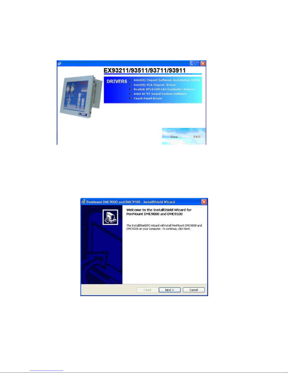
2. Insert the TOPSCCC product cd install setup.exe. the screen below would appear.
Click touch panel driver
3. The screen displays the installation wizard for the PenMount software. Click “Next”.
Page 63
EX-93211/93511/93711/93911User Manual
63
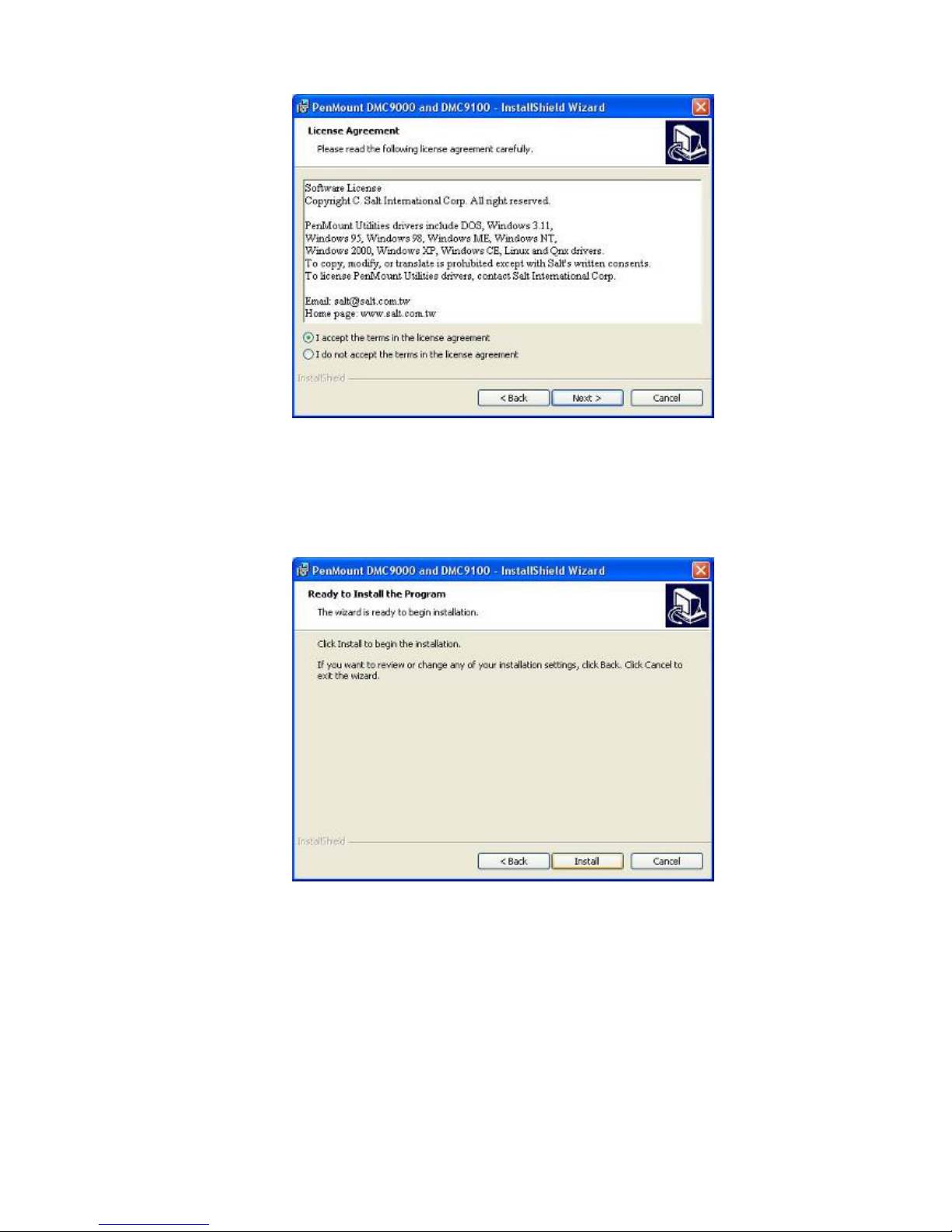
3.1 A License Agreement appears. Click “I accept…” and “Next”
4. The “Ready to Install the Program” screen appears. Select “Install”.
Page 64
EX-93211/93511/93711/93911User Manual
64
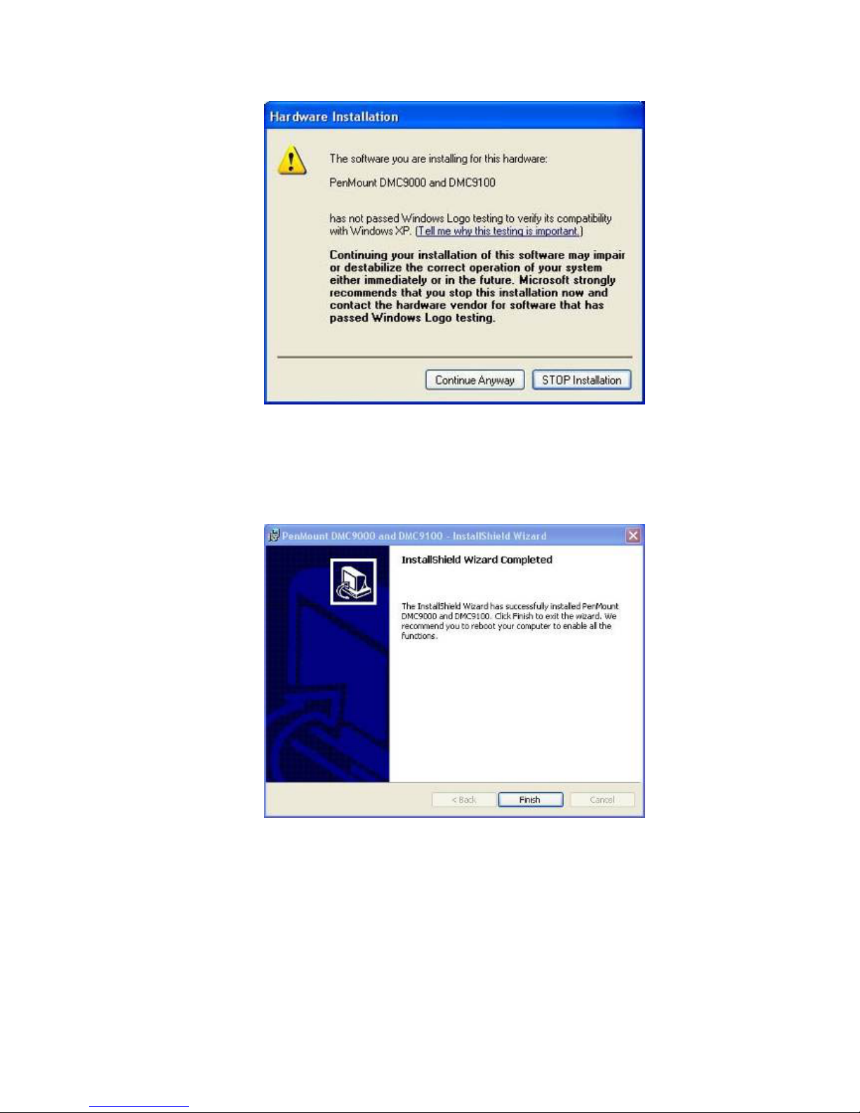
5. The next screen is “Hardware Installation”. Select “Continue Anyway”.
6. The “InstallShield Wizard Completed” appears. Click “Finish”.
Page 65
EX-93211/93511/93711/93911User Manual
65
5.3 Configuring the PenMount Windows 2000/XP Driver
Upon rebooting, the computer automatically finds the new 9036 controller board. The
touch screen is connected but not calibrated. Follow the procedures below to carry out
calibration.
1. After installation, click the PenMount Monitor icon “PM” in the menu bar.
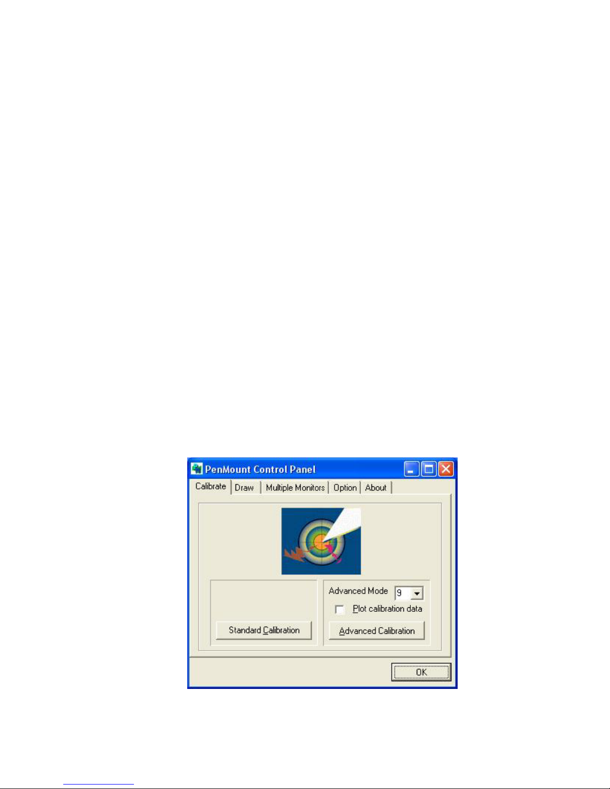
2. When the PenMount Control Panel appears, click “Calibrate”.
PenMount Control Panel
The functions of the PenMount Control Panel are Calibrate, Draw, Multiple Monitors,
Option, and About, which are explained in the following sections.
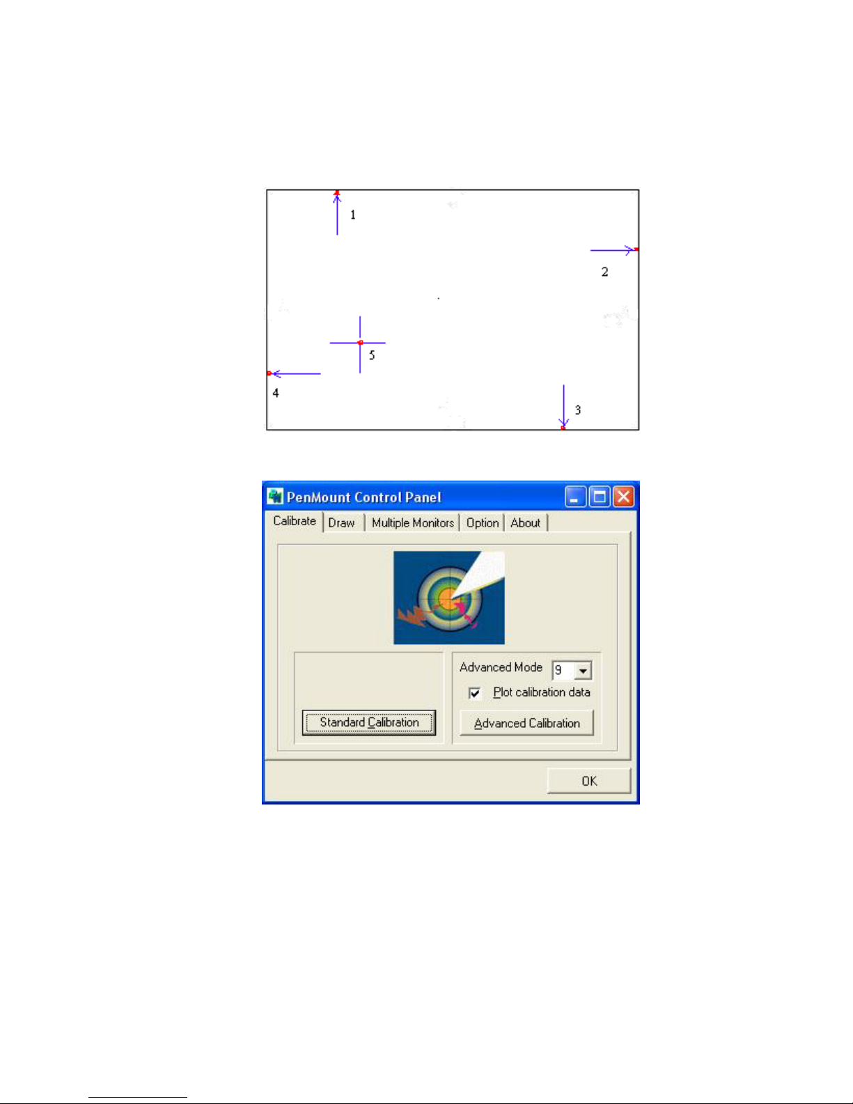
Calibrate
This function offers two ways to calibrate your touch screen. “Standard Calibration”
adjusts most touch screens. “Advanced Calibration” adjusts aging touch screens.
Standard Calibration
Click this button and arrows appear pointing to red
squares. Use your finger or stylus to touch the red
squares in sequence. After the fifth red point
calibration is complete. To skip, press ‘ESC’.
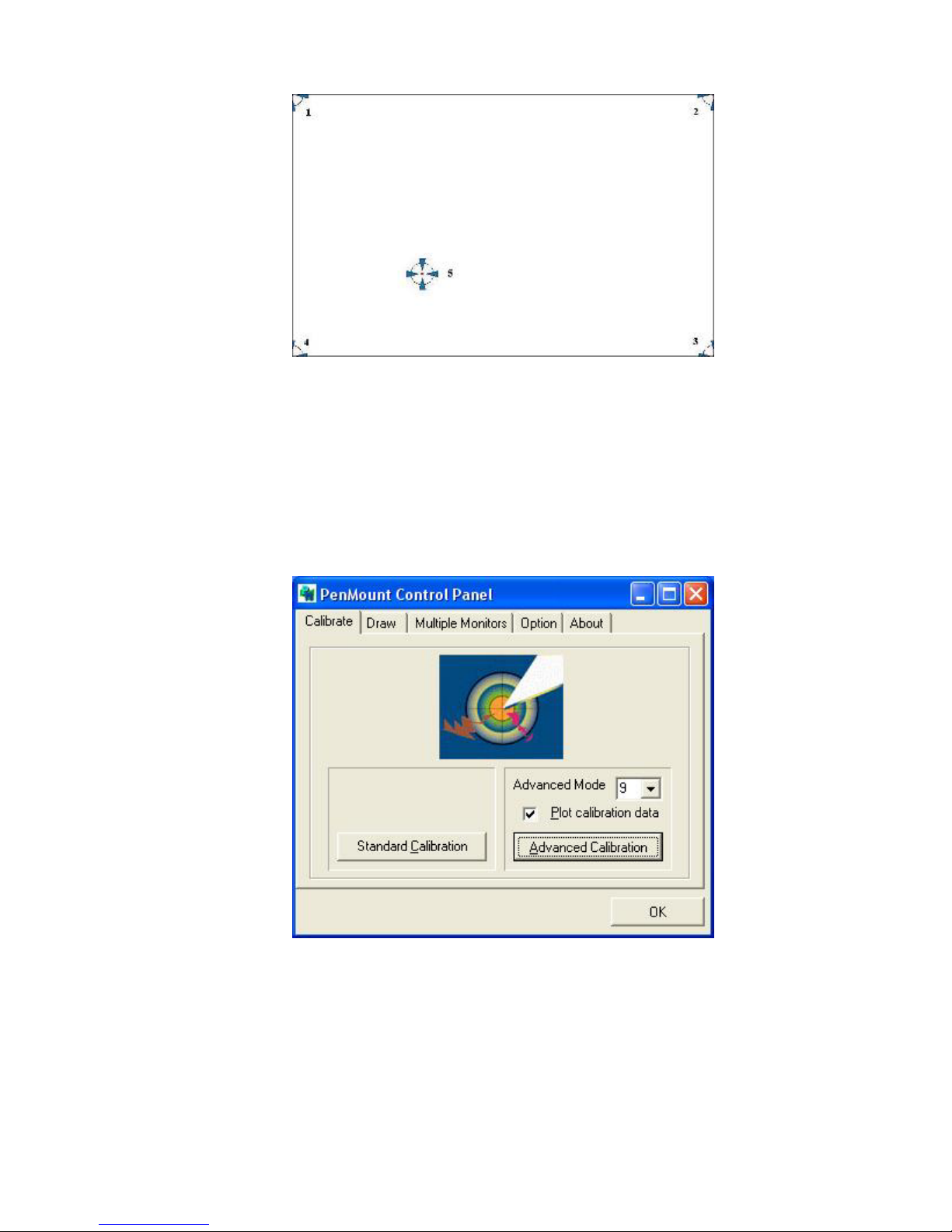
Advanced Calibration Advanced Calibration uses 4, 9, 16 or 25 points to
effectively calibrate touch panel linearity of aged
touch screens. Click this button and touch the red
squares in sequence with a stylus. To skip, press
‘ESC’.
Page 66
EX-93211/93511/93711/93911User Manual
66
NOTE: The older the touch screen is, the more Advanced Mode calibration points you need
for an accurate calibration. Use a stylus during Advanced Calibration for greater
accuracy.
Page 67
EX-93211/93511/93711/93911User Manual
67
Plot Calibration Data Check this function and a touch panel linearity
comparison graph appears when you have finished
Advanced Calibration. The blue lines show linearity
before calibration and black lines show linearity
after calibration.
Page 68
EX-93211/93511/93711/93911User Manual
68
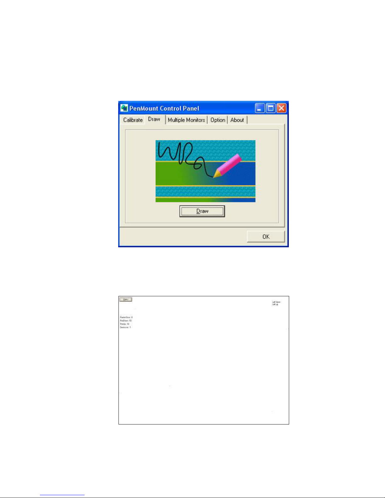
Draw
Tests or demonstrates the PenMount touch screen operation. The display shows touch
location. Click Draw to start. Touch the screen with your finger or a stylus and the
drawing screen will register touch activity such as left, right, up, down, pen up, and
pen down.
Touch the screen with your finger or a stylus and the drawing screen will register touch
activity such as left, right, up, down, pen up, and pen down.
Page 69
EX-93211/93511/93711/93911User Manual
69
Click Clear Screen to clear the drawing.
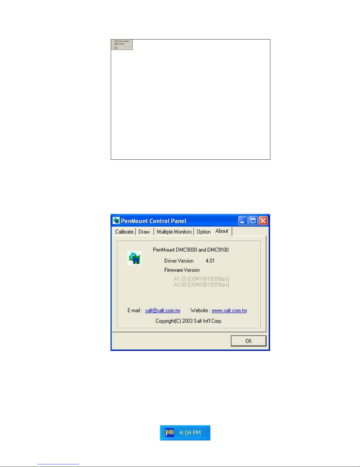
About
This panel displays information about the PenMount controller and this driver version.
PenMount Monitor Menu Icon
The PenMount monitor icon (PM) appears in the menu bar of Windows 2000/XP system
when you turn on the PenMount Monitor in the PenMount Utilities.
Page 70

EX-93211/93511/93711/93911User Manual
70
The PenMount Monitor has the following functions:
Page 71

EX-93211/93511/93711/93911User Manual
71
Beep Turns beep on or off.
Right Button When you select this function, a mouse icon appears
in the right-bottom of the screen. Click this icon to
switch between Right and Left Button functions.
Pen Stabilizer Check this function to reduce cursor vibration for
relatively unstable touch screens, or where there may
be excess vibration. Normally this function is not
checked.
Exit Exits the PenMount Monitor function.
Page 72
EX-93211/93511/93711/93911User Manual
72
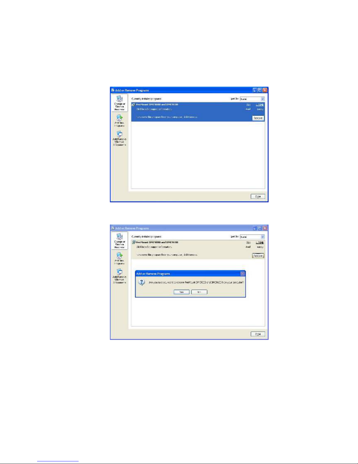
5.5 Uninstall the PenMount Windows 2000/XP Driver
1. Exit the PenMount monitor (PM) in the menu bar.
2. Go to Settings, then Control Panel, and then click Add/Remove program. Select
PenMount DMC9000 and click the Add/Remove button.
3. Select PenMount DMC9000 and DMC9100. Click the Remove button.
4. Select “Yes” and “Close” to remove the PenMount Windows 2000/XP driver, and
reboot the system.
Page 73
EX-93211/93511/93711/93911User Manual
73
Appendix A:
A. Panel Mounting
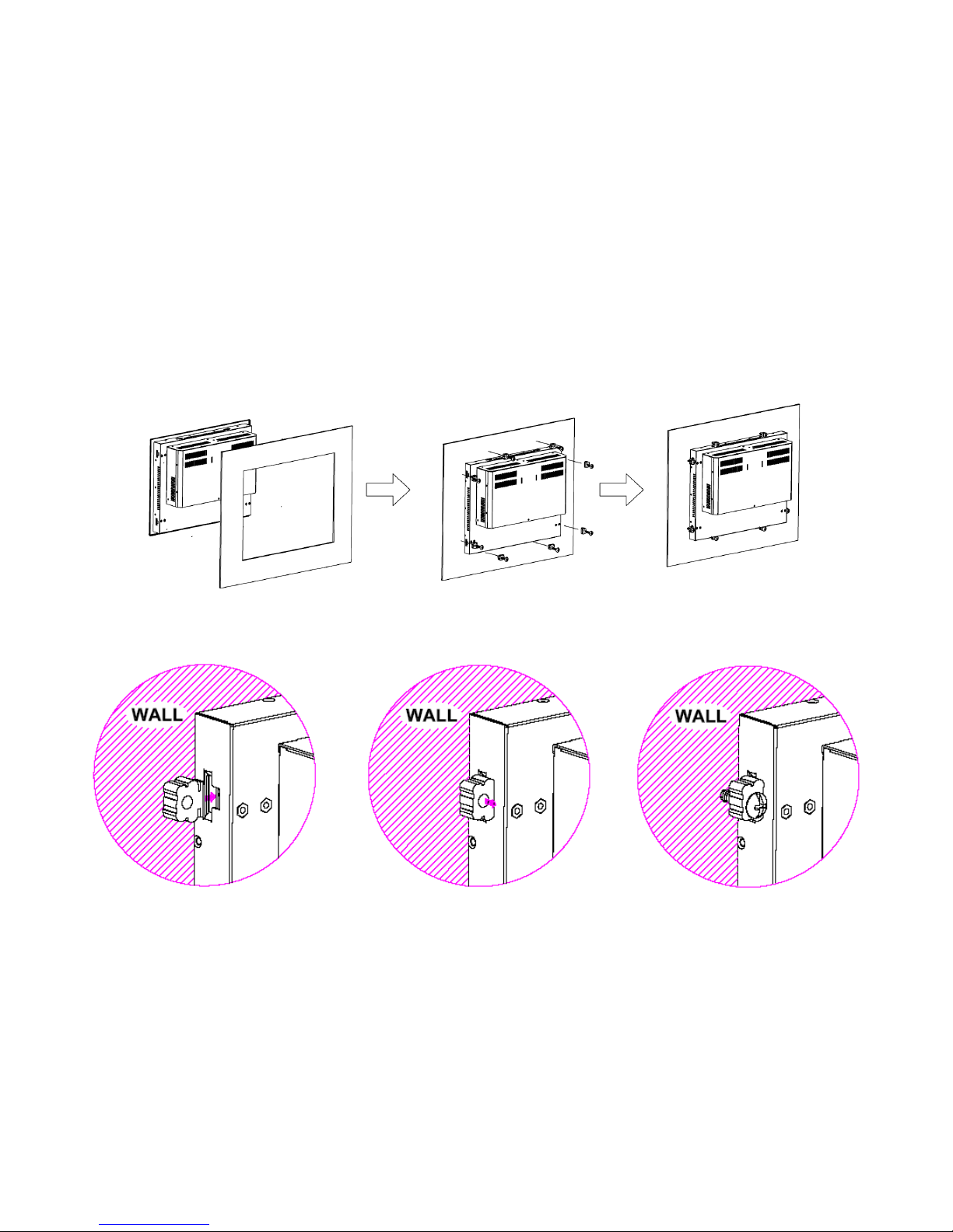
The EX-93211/93511/93711/93911 panel PC is designed to be panel-mounted as shown in Figure A.
Just carefully place the unit through the hole and tighten the given 8 screws from the rear to secure
the mounting.
Figure A: Panelmounting of the EX-93211/93511/93711/93911
Page 74
EX-93211/93511/93711/93911User Manual
74
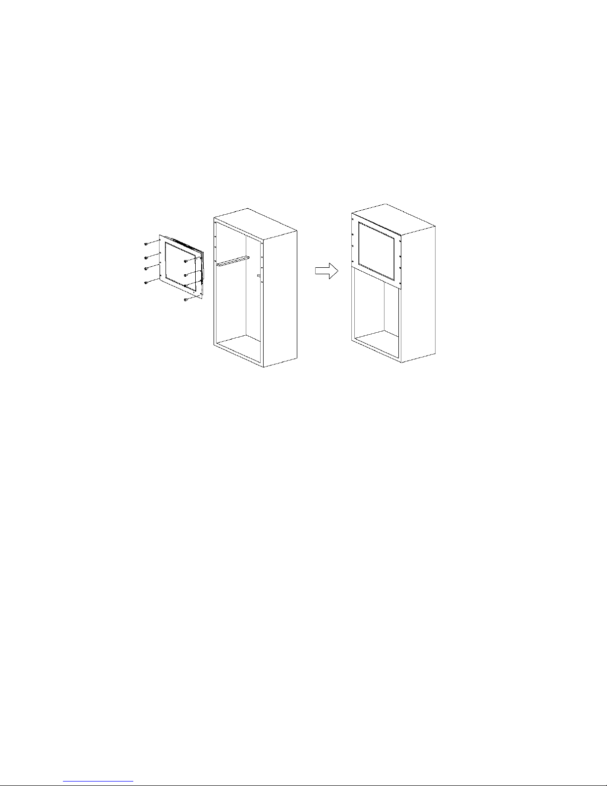
B. Rack Mounting (optional)
The EX-93211/93511/93711/93911 panel PC can be rack-mounted as an option. Just carefully slide it
into the rack and tighten the given 8 screws from the front to secure the mounting as shown in Figure
B.
Figure B: Rackmounting of the EX-93211/93511/93711/93911
 Loading...