

TOPSCCC EX-9686U-L series Hardware User Manual

EX-9686U-L Series
Hardware User Manual

EX-9686U-L Series Hardware User Manual
Page 2
Release Notes
Version Release Date Notes
1.20 October 1st , 2013 The 2nd release to customer
1.30 October 30th , 2013 Add more interfaces info
Disclaimer
This documentation is provided for use with TOPSCCC products. No license to TOPSCCC
property rights is granted. TOPSCCC assumes no liability and provides no warranty either
expressed or implied relating to the usage or intellectual property right infringement that
may result from its use.
TOPSCCC provides this document “as is,” without warranty of any kind, expressed or
implied, including, but not limited to, its particular purpose. TOPSCCC may make changes
to this document without notice.

Page 3
Table of Contents
TABLE OF CONTENTS...........................................................................................3
1 PRECAUTIONS...............................................................................................5
1.1 Safety Precautions.........................................................................................5
1.2 Write Prohibited Regions ................................................................................6
1.3 Warranty .......................................................................................................6
2 PRODUCT FEATURES.....................................................................................7
2.1 Overview.......................................................................................................7
2.2 Features and Specifications............................................................................8
3 INTERFACE SPEC - I ...................................................................................10
3.1 HDMI Connector..........................................................................................12
3.2 MicroSD Connector......................................................................................13
3.3 UART Connectors & Debug Port ...................................................................14
3.4 USB Connectors..........................................................................................17
3.5 Audio Interface ............................................................................................19
3.6 Ethernet Interface ........................................................................................20
3.7 Power Supply (DC-IN connector)...................................................................21
3.8 GPIO Pin Header.........................................................................................22
3.9 I
2
C Interface ................................................................................................24
3.10 CAN Bus Interface .....................................................................................25
3.11 BM Connector ............................................................................................26
4 INTERFACE SPEC - II....................................................................................27
4.1 Parallel Display Interface ..............................................................................29
4.2 LVDS Display Interface.................................................................................31
4.3 Touch Screen Interface.................................................................................33
4.4 Power Output Connector ..............................................................................34
4.5 Camera Sensor Interface..............................................................................35
4.6 MIPI Interface..............................................................................................36
4.7 Expansion Connector ...................................................................................37
4.8 Keypad Connector .......................................................................................38
4.9 Mini-PCIe Connector....................................................................................39
4.10 SATA Interface ...........................................................................................40

Page 4
5 EX-9686U-L PCB OUTLINE DRAWING..............................................................41
APPENDIX A: BOX HEADER TO DB9 CABLE........................................................43
APPENDIX B: 7-INCH LCD BRIEF (WVGA)............................................................44
APPENDIX C: 7-INCH LCD BRIEF (WSVGA)..........................................................46
APPENDIX D: 10.1-INCH LCD BRIEF ....................................................................48
APPENDIX E: 15-INCH LCD BRIEF .......................................................................49
APPENDIX F: 15-INCH LCD BRIEF (HIGH BRIGHTNESS).......................................51
APPENDIX G: 21.5-INCH LCD BRIEF ....................................................................53

EX-9686U-L Series Hardware User Manual
Page 5
1 Precautions
1.1 Safety Precautions
In order to use this product safely, please take special note of the following precautions.
• Read all product manuals and related documentation before using this product. Use
this product correctly and safely. Follow all warnings.
• If operating or extending this product in a manner not described in this manual,
please do so at your own risk. Be sure to fully read this manual and other technical
information on our website and proceed safely and responsibly.
• Do not install this product in a place with a lot of water, moisture, dust or soot. This
could cause product failure, fire, or an electric shock.
• Some parts of this product generate heat and can reach high temperatures. This
may cause burns if it is improperly handled. Do not touch the electronic components
or surrounding area while powered on or immediately after being turned off.
• Carry out any design and development only after you have thoroughly read and
understood this manual and any other related technical materials on the website or
in the data sheets. Test your product thoroughly for reliability and safety.
• This product is not intended for applications that require extremely high reliability,
safety, functionality and accuracy: including but not limited to medical equipment,
traffic control systems, combustion control systems, and safety equipment. This
company is not liable for death or injury if used in such systems.
• This product uses semiconductor components designed for generic electronics
equipment such as office automation, communications, measurement equipment
and machine tools. Foreign noise or a power surge may cause this product to
malfunction or fail.
• To ensure there is no risk of bodily harm or property damage, be sure to take all
electrical safety precautions such as protection circuits, limit switches, fuse breakers,
or redundant systems. Only use the device after sufficient reliability and safety
measures are in place.

EX-9686U-L Series Hardware User Manual
Page 6
1.2 Write Prohibited Regions
1.3 Warranty
As described in the Product Warranty Policy provided with this product, the main board is
covered by a one year replacement warranty starting from the time of purchase. Please
note that the other included goods and software are not covered under this warranty. Some
knowledge used by TOPSCCC is provided by third parties, and TOPSCCC makes no
representation or warranty as to the accuracy of such information.
Data stored by the EEPROM, iMX6Q/D electrical fuse (e-Fuse) is used by the software
contained in this product. Do not write to these regions as this may cause the product
stop working correctly. Purposely writing to these regions voids the product warranty.

EX-9686U-L Series Hardware User Manual
Page 7
2 Product Features
2.1 Overview
The EX-9686U-L is a series of Freescale iMX6 ARM Cortex-A9 based embedded computer
products with a rich set of features. It is a flexible, high performance and inexpensive
computer platform designed for multimedia applications such as digital signage, in-vehicle
infortainment, KIOSK or HMI.
Each device can be installed in advance with Windows Embedded Compact 7, Ubuntu
11.10 or Android 4.2 for immediate evaluation.

EX-9686U-L Series Hardware User Manual
Page 8
2.2 Features and Specifications
Features
¾ High performance Cortex A9 processor (quad/dual/single core)
¾ Dedicated hardware MPEG2/4/H.264 1920x1080 Full HD decoder
¾ Dedicated hardware H.264 1920x1080 Full HD encoder
¾ Hardware 2D/3D graphics accelerator
¾ Preinstalled Windows Embedded Compact 7, Ubuntu 11.10 or Android 4.2 OS
¾ Rich set of peripherals (LCD, USB, HDMI, …etc)
EX-9686U-L Series Specifications
z Freescale iMX6 ARM Cortex™-A9 core @ 1 GHz, 32 KB L1 cache, 512 KB L2 cache
z 1GB DDR3 SDRAM (Single Core with 512MB DDR3 only)
z 4GB eMMC Flash
z Hardware Video Decoder
H.264 HP profile (up to 50 Mbps)
MPEG 1/2 MP profile (up to 50 Mbps)
MPEG 4 SP/ASP profile (up to 40 Mbps)
VC1 SP/MP/AP profile (up to 45 Mbps)
z Hardware Video Encoder
MPEG 4 Simple profile 720P 30fps (up to 12 Mbps)
H.264 BP/CBP profile 1080P 30fps (up to 14 Mbps)
z 10/100/1000 Mbps Gigabit Ethernet interface RJ-45 connector x1
z Single parallel 24-bit display port, up to 225 Mpixels/sec
z LVDS serial ports - Single port up to 165 Mpixels/sec or dual ports up to 85 MP/sec
z 7”, or 10.1” LCD panel with touch screen x1
z HDMI 1.4 transmitter connector x1
z +12V DC power input connector x1
z USB 2.0 host connector x2
z USB 2.0 OTG connector x1
z Micro SD card socket x1
z SATA x1
z SGTL5000 Audio Codec , Amplifier circuit
z MIC-in connector x1, Earphone connector x1
z Speaker connector x2 (L/R)
z RS485 connector x1
z RS232 connector x2 (one for debug port)

EX-9686U-L Series Hardware User Manual
Page 9
z GPIO pin header x1 (8 bits for Standard; 16 bits for Optional)
z CAN bus phoenix connector x 1 (Optional)
z IEEE 802.11 b/g/n Wi-Fi x 1 (Optional)
z mini PCI-E for 3G module x 1 (Optional)
z MIPI interface x 1 (Optional)
z Board Dimension: 101mm x146mm

EX-9686U-L Series Hardware User Manual
Page 10
3 Interface Spec - I
The following photos and diagrams show connector positions on the EX-9686U-L series of
products respectively. The functional details of the connectors are described in subsequent
sections.
Major connectors of EX-9686U-L PCB:
EX-9686U-L Top View

EX-9686U-L Series Hardware User Manual
Page 11
EX-9686U-L PCB Bottom View
Connector positions of EX-9686U-L series:

EX-9686U-L Series Hardware User Manual
Page 12
3.1 HDMI Connector
The HDMI receptacle connector supports a standard HDMI interface. Its features include:
z HDMI 1.4a, HDCP 1.4, DVI 1.0 compliant
z Hot plug/unplug detection and link status monitor supported
z Video resolutions supported:
Up to 1080p@120Hz HDTV display
QXGA graphics display
HDMI 1.4a 4K x 2K video formats
HDMI 1.4a 3D video modes with up to 340MHz TMDS clock
z Supported color formats:
24/30/36/48-bit RGB 4:4:4
24/30/36/48-bit YCbCr 4:4:4
16/20/24-bit YCbCr 4:2:2
z All audio formats as specified by the HDMI Specification Version 1.4a are supported
HDMI pin out
Pin Signal Pin Signal
1 TMDS Data2+ 11 TMDS Clock Shield
2 TMDS Data2 Shield 12 TMDS Clock−
3 TMDS Data2− 13 CEC
4 TMDS Data1+ 14 NC
5 TMDS Data1 Shield 15 SCL
6 TMDS Data1− 16 SDA
7 TMDS Data0+ 17 Ground
8 TMDS Data0 Shield 18 +5V
9 TMDS Data0− 19 Hot plug detect
10 TMDS Clock+
EX-9686U-L Series Hardware User Manual
Page 13
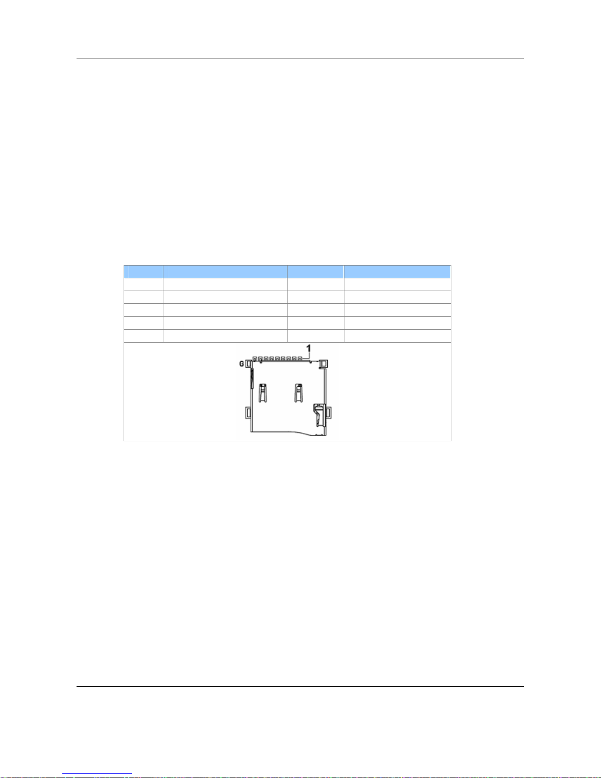
3.2 MicroSD Connector
The microSD host connector has the following specification:
z SD Host Controller Standard Specification version 3.0
z MMC System Specification version 4.2/4.3/4.4
z SD Memory Card Specification version 3.0 and supports the Extended Capacity SD
Memory Card
z SDIO Card Specification version 3.0
microSD Connector Pin-out
Pin Signal Pin Signal
1 Data 2 6 GND
2 Data 3 7 Data 0
3 CMD 8 Data 1
4 VDD 9 CD
5 CLK

EX-9686U-L Series Hardware User Manual
Page 14
3.3 UART Connectors & Debug Port
There are 3 UART ports on this device. The connector type and functions are described in
the table below:
UART
Number
Connector
Type
Available
Signals
Notes
UART1
2x4 box
header
RS232 signal level
(TX, RX, RTS, CTS)
Console/Debug port
UART2
2x4 box
header
RS232 signal level
(TX, RX, RTS, CTS)
RS232 port
UART3
2x4 box
header
RS485 signal level
(485+, 485-)
RS485 port
Note: RS485 port works only in
HALF Duplex mode
One 2x4 box header to DB9 cable is included. See Appendix A for the detailed info on the
cable pin assignment.
2x4 Box Header:
DB9
Pin
2x4
header
RS232 RS485
1 -- --- --2 4 RxD 485+
3 6 TxD 4854 1 --- --5 5 GND GND
6 7 --- --7 8 RTS --8 2 CTS --9 -- --- ---
1
2
7
8
EX-9686U-L Series Hardware User Manual
Page 15
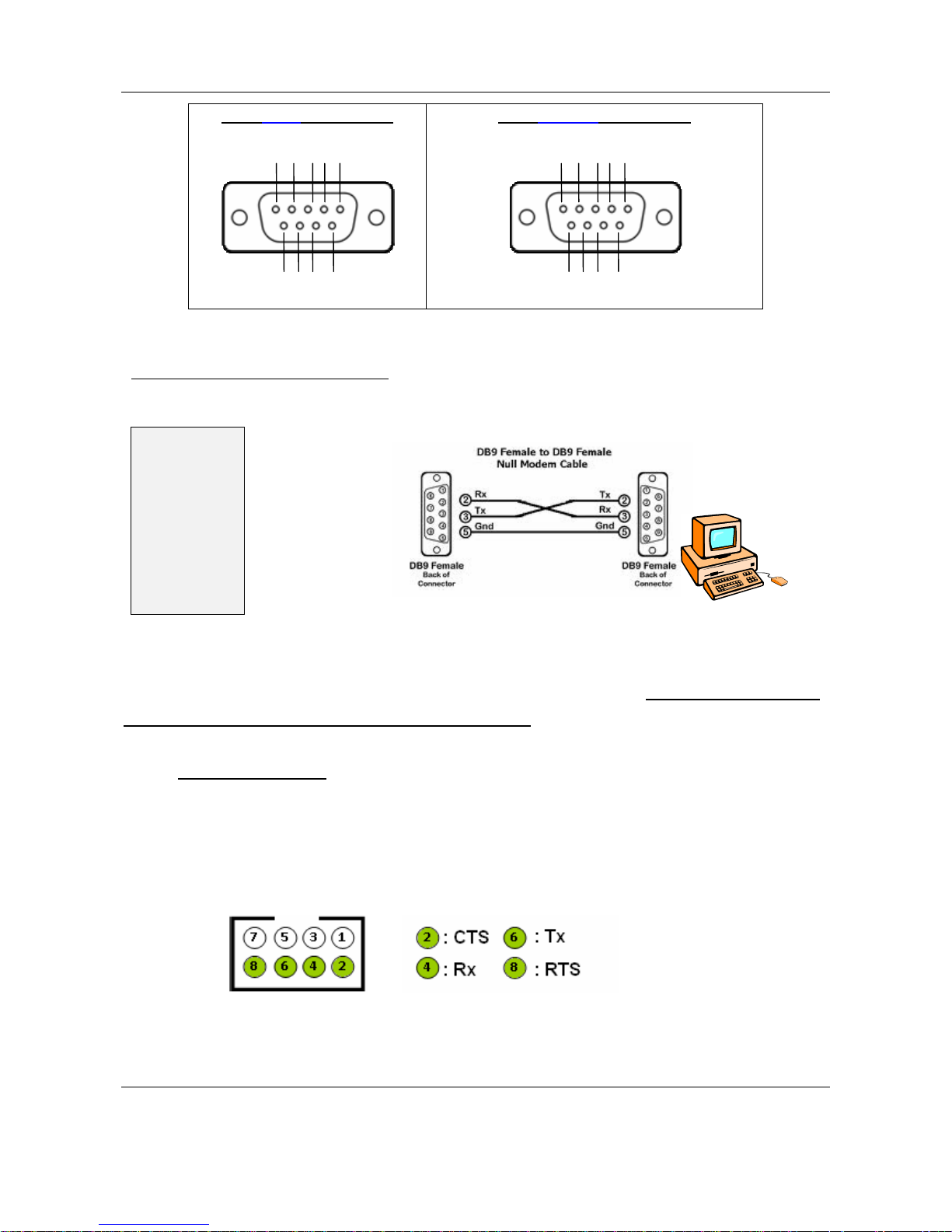
DB9 Male Connector
DB9 Female Connector
UART1 is dedicated as the debug port. UART1 default settings are Baud Rate 115200, 8
data bits, no parity, 1 stop bit and no flow control.
A DB9 null modem cable (or adapter) is required when you want to connect UART1 to a
PC with terminal emulation software such as TeraTerm.
UART1 Box Header (CN3 on PCB) Pin Assignment:
1 2 3 4 5
6 7 8 9
54 321
987 6
UART1 Connection Diagram:
SBC/NSD
/EC 21
UART1
EX-9686U-L Series Hardware User Manual
Page 16
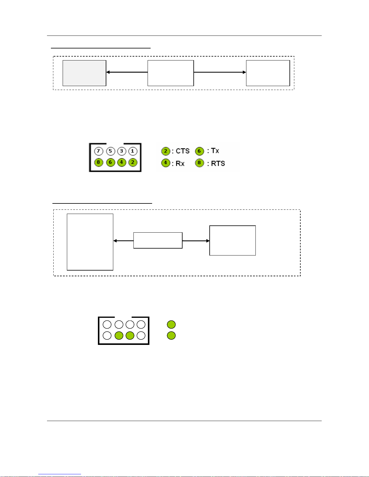
UART2 Box Header (CN2 on PCB) Pin Assignment:
UART3 Box Header (CN1 on PCB) Pin Assignment:
UART2 (with TX, RX, RTS, CTS signals) works as a regular RS232 port.
iMX6
CPU
RS232
Transceiver
2x4
Box Header
TX, RX
RTS, CTS
UART3 Connection Diagram:
ZT485E: RS485 transceiver. RS485 works in half duplex mode.
iMX6
CPU
2x4
Box Header
ZT485E
UART2 Connection Diagram:
1
2
3 5 7
4 6 8
4
6
: 485+
: 485-
EX-9686U-L Series Hardware User Manual
Page 17
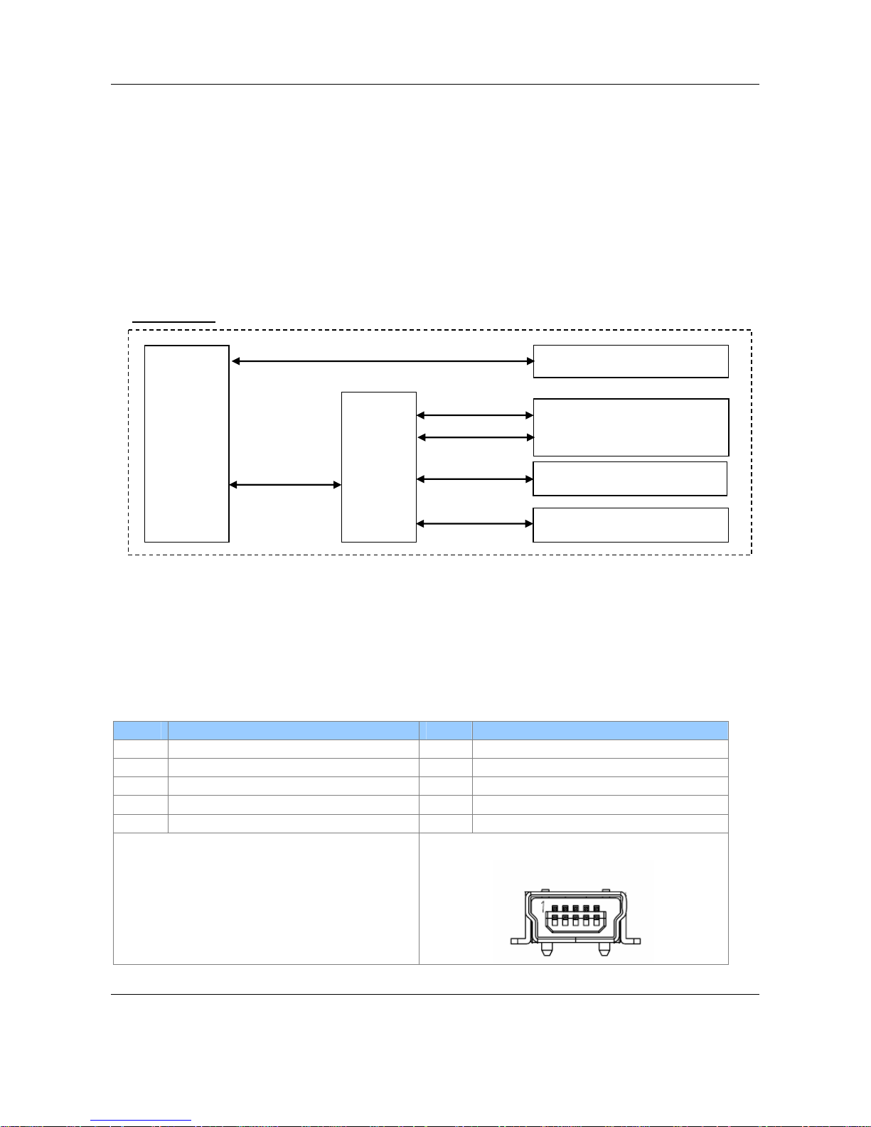
3.4 USB Connectors
The USB interfaces on EX-9686U-L include a USB 2.0 OTG port and two USB2.0 host
ports. Speed of up to 480 Mbps supported.
The USB 2.0 host interface is connected to a hub controller to extend host ports. Two of the
USB2.0 hub ports are available for users. The other two USB ports are reserved for
802.11b/g/n WiFi module and 3G (WCDMA) module.
NOTE: The USB 2.0 OTG can be used in host mode or device mode. If you would like to
use it in host mode, a separate OTG-to-host cable is required.
The USB 2.0 host connector is a regular USB type A connector that can be connected to
+5V USB storage device. This port is mainly used to connect to USB flash drive.
Pin Signal Pin Signal
1 5V 1 5V
2 Data - 2 Data 3 Data + 3 Data +
4 GND 4 ID
5 GND
USB Port:
iMX6
CPU
4-port
Hub
USB2.0 Connectors
(type-A)
USB2.0 OTG
USB2.0 Host
USB2.0 OTG Connector
USB2.0 (header for WiFi)
USB2.0 (PCI-e for 3G)
 Loading...