

Page 1

EX-96085 User Manual
1
EX-96085
(Human Machine Interface)
User Manual
“The Human Machine Interface is where people and technology meet.”
Release Date Revision
Sep 2006 V0.1
®2005 TOPSCCC Technology, Inc. All Rights Reserved. Published in
Taiwan
TOPSCCC Technology, Inc.
5F, NO. 12, ALLEY 345, Yang-Guang ST. , Nei-Hu, Taipei, Taiiwan R.O.C
Tel:886-2-27999080 Tel:886-2-26585042, 26575516 E-mail: [email protected] URL:
www.topsccc.com
Page 2

EX-96085 User Manual
2
Warning!___________________________________
Disclaimer
This information in this document is subject to change without notice. In no event shall
TOPSCCC Technology Inc. be liable for damages of any kind, whether incidental or
consequential, arising from either the use or misuse of information in this document or in any
related materials.
This equipment generates, uses and can radiate radio frequency energy and if not installed and
used in accordance with the instructions manual, it may cause interference to radio communica-
tions. It has been tested and found to comply with the limits for a Class A computing device
pursuant to FCC Rules, which are designed to provide reasonable protection against such
interference when operated in a commercial environment. Operation of this equipment in a
residential area is likely to cause interference in which case the user at his own expense will be
required to take whatever measures may be required to correct the interference.
Electric Shock Hazard – Do not operate the workstation with its back cover removed. There are
dangerous high voltages inside.
Page 3

EX-96085 User Manual
3
Table of Contents______________________
Warning!…………………………………………………………………………….……..….2
Disclaimer………………………………………………………………….…………………2
Chapter 1 Introduction
1.1 Features.............................................................................................................6
1.2 Specifications..................................................................................................... 6
1.3 Dimensions ........................................................................................................8
1.4 Block Diagram....................................................................................................9
1.5 Mainboard ..........................................................................................................9
1.6 Brief Description of the EX-96085....................................................................12
Chapter 2 System Installation
2.1 Installation of the EX-96085 .............................................................................13
Chapter 3 Mainboard Configuration
3.1 JUMPER & CONNECTOR QUICK REFERENCE TABLE ...............................16
3.2 COMPONENT LOCATIONS ............................................................................17
3.3 HOW TO SET THE JUMPERS ........................................................................18
3.4 COM 1 RI & VOLTAGE SELECTION ...............................................................20
3-5. COM 2 RI & VOLTAGE SELECTION..............................................................20
3-6. COM 3 RI & VOLTAGE SELECTION..............................................................20
3-7. COM 4 RI & VOLTAGE SELECTION..............................................................20
3.8 RS232/422/485 (COM2) SELECTION .............................................................24
3.9 BRIGHTNESS VOLTAGE SELECTION ...........................................................25
3.10 LVDS VOLTAGE SELECTION .......................................................................25
3.11 LVDS PANEL RESOLUTION SELECTION .................................................... 26
3.12 CMOS FUNCTION SELECTION ...................................................................26
3.13 RESET / NMI SELECTION ............................................................................27
3.14 CPU_VCCA VOLTAGE SELECTION .............................................................27
3.15 CPU FREQUENCY SELECTION...................................................................28
3.16 COM PORT CONNECTOR............................................................................28
3.17 VGA CONNECTOR........................................................................................31
3.18 LVDS CONNECTOR......................................................................................32
3.19 POWER CONNECTOR .................................................................................33
3.20 HARD DISK DRIVE CONNECTOR................................................................34
3.21 PRINTER CONNECTOR ...............................................................................35
3.22 LAN CONNECTOR ........................................................................................36
Page 4

EX-96085 User Manual
4
3.23 LAN LED CONNECTOR ................................................................................36
3.24 KEYBOARD CONNECTOR ...........................................................................37
3.25 PS/2 MOUSE CONNECTOR .........................................................................37
3.26 HDD LED CONNECTOR ...............................................................................38
3.27 POWER BUTTON..........................................................................................38
3.28 POWER LED CONNECTOR .........................................................................38
3.29 UNIVERSAL SERIAL BUS CONNECTOR.....................................................39
3.30 MEMORY INSTALLATION .............................................................................41
3.31 INVERTER CONNECTOR.............................................................................41
3.32 POWER MODULE .........................................................................................42
3.33 COMPACT FLASH CONNECTOR.................................................................43
3.34 PCI-104 CONNECTOR..................................................................................44
3.35 CPU FAN CONNECTOR ...............................................................................45
3.36 SYSTEM FAN CONNECTOR ........................................................................46
3.37 SERIAL ATA CONNECTOR ...........................................................................46
3.38 RESET & SPEAKER CONNECTOR..............................................................47
Chapter 4 Software Utility
4.1 Introduction to Software Utilities.......................................................................48
4.2 VGA DRIVER UTILITY.....................................................................................48
4.3 FLASH BIOS UPDATE.....................................................................................49
4.4 LAN DRIVER UTILITY .....................................................................................50
4.5 SOUND DRIVER UTILITY ...............................................................................51
4.6 INTEL® C HIPSET SOFTWARE INSTALLATION UTILITY .............................52
4.7 USB2.0 SOFTWARE INSTALLATION UTILITY ...............................................53
4.8. SERIAL ATA DRIVER UTILITY .......................................................................54
4.9 WATCHDOG TIMER CONFIGURATION .........................................................55
Chapter 5 AWARD BIOS Setup
5.1 Introduction to Award Bios Setup .....................................................................56
5.2 ENTERING SETUP..........................................................................................56
5.3 THE STANDARD CMOS FEATURES..............................................................58
5.4 THE ADVANCED BIOS FEATURES ................................................................62
5.5 ADVANCED CHIPSET FEATURES .................................................................64
5.6 INTEGRATED PERIPHERALS ........................................................................66
5.7 POWER MANAGEMENT SETUP....................................................................69
5.8 PNP/PCI CONFIGURATION............................................................................70
5.9 PC HEALTH STATUS.......................................................................................72
5.10 FREQUENCY CONTROL ..............................................................................73
5.11. LOAD FAIL-SAFE DEFAULTS ......................................................................73
5.12. LOAD OPTIMIZED DEFAULTS.....................................................................74
Page 5

EX-96085 User Manual
5
5.13. PASSWORD SETTING.................................................................................74
5.14 SAVE & EXIT SETUP.....................................................................................75
5.15 EXIT WITHOUT SAVING ...............................................................................75
Chapter 6 Touch Driver Installation
6.1 Introduction to the TB-31 Touch Screen Controll Board………………….……..77
6.2 Configuring the PenMount Windows 2000/XP Driver.......................................81
6.3 Uninstall the PenMount Windows 2000/XP Driver ...........................................88
6.4 Software Functions ..........................................................................................89
Appendix: Mainboard Technical Summary 91
Page 6

EX-96085 User Manual
6
Chapter 1 Introduction
1.1 Features
z High performance Celeron M/Pentium M CPU support
z 8” SVGA TFT LCD with high luminance
z Low power consumption with fanless cooling system
z NEMA 4/IP 65 compliant front panel
z Panel mount and VESA 75 mounting support
z Resistive touch screen
z DC 11~28V wide range power input
z Support Windows 2000/XP, XP embedded and CE.NET
1.2 Specifications
System
CPU:
Celeron M 600MHz or 1.0GHz without L2 cache
System Memory:
256MB up to 1GB DDRAM
Slot:
One 40GB HDD, One compact flash drive (optional)
Power Supply:
Input voltage range of 10.8~28V
Touch Screen:
Touch screen with 4-wire, analog resistive; resolution of 800 x 600,
light transmission of above 80%; and life of 1 million activations (minimum)
I/O Connectors:
Serial ports: 2 (COM1: RS-232, COM2: RS232/422/485, COM3: reserved, COM4: for touch screen)
Ethernet port (10/100 base-T) x 1;
USB port) x 2,
Parallel port x 1;
Stereo audio mic-in, line-in and line-out x 1;
PS/2 keyboard x 1; and
PS/2 mouse x 1
EMC:
FCC, CE Class A certified
Page 7

EX-96085 User Manual
7
Display
Resolution, color, and luminance:
8 inches TFT LCD with resolution of 800x600, 262k colors, 400 cd/m
2
Mechanical
Construction:
Metal allow housing
Color:
Black front panel
Dimensions:
231(W) x 81(D) x 176(H)mm
Weight:
1.4 kg
Environment
Operating temperature:
0~50 C°
Storage temperature:
0~70°C
Relative humidity:
10~95% @ 40°C non-condensing
Vibration:
5~17Hz, 0.1” double amplitude displacement
17~640Hz, 1.5G acceleration peak to peak
Shock:
10G acceleration peak to peak (11 millimeters)
Page 8
EX-96085 User Manual
8
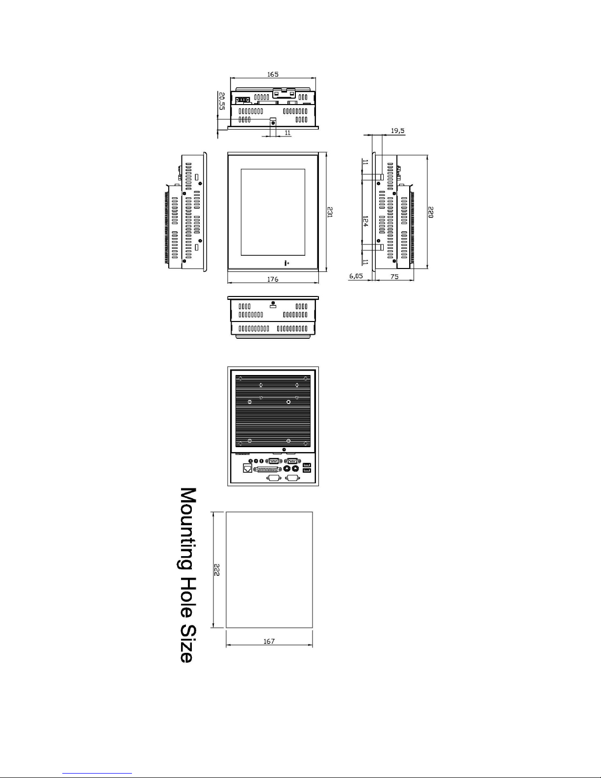
1.3 Dimensions
Figure 1.1: Dimensions of the EX-96085
Page 9
EX-96085 User Manual
9
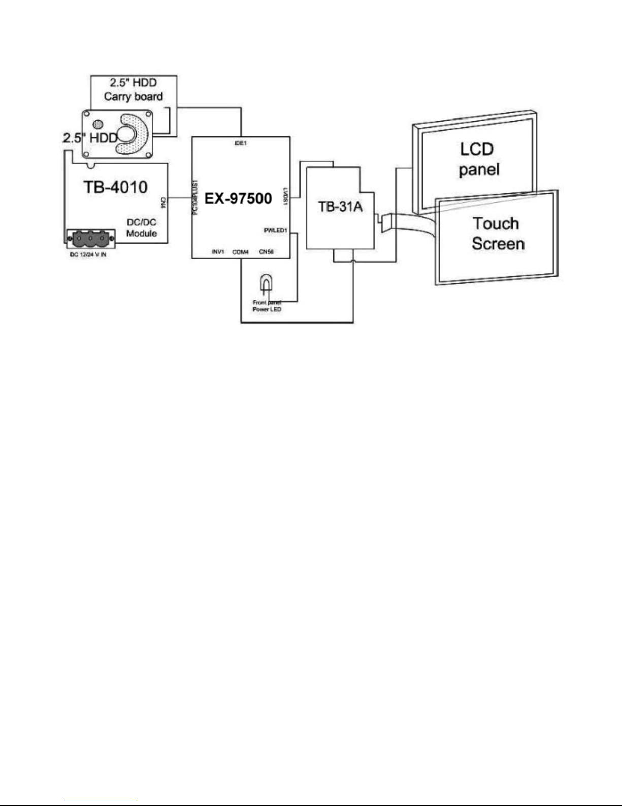
1.4 Block Diagram
Figure 1.2: Block Diagram of the EX-96085
1.5 Mainboard
Specifications
CPU:
Socket 478 Intel Celeron® M up to 1.0GHz Auto detect voltage regulator.
Chipset:
Intel® 855GME+ICH4
DRAM:
One 200-pin DDRAM SO-DIMM up to 1GB
Cache:
Built-in CPU
BIOS:
Phoenix-Award Flash BIOS for plug & play function. Memory size with 4MB and with VGA BIOS.
Page 10

EX-96085 User Manual
10
Support S I/O Setup
IDE Interface:
One EIDE (UDMA-33/66/100) support 2 IDE devices, one compact flash type II onboard
Serial Port:
Four high speed 16550 Compatible UARTs with Send / Receive 16 Byte FIFOs.
Parallel Port:
One parallel (SPP/EPP/ECP)
CMOS:
Built-in chipset with external battery
Keyboard and Mouse:
PS/2 (mini DIN connector)
Speaker:
Internal buzzer and external speaker connector
VGA:
Integrated in Built-in Intel 855GME, share system memory, support CRT, LVDS
LAN:
Intel 82541 Chip. RJ-45 jack onboard, Support for 10/100/1000 Base-T Ethernet.
Support Wake-On-LAN function.
Sound:
AC ’97 Codec, ALC202A, with line-in, line-out, mic
USB:
Two USB 2.0
Expansion Bus:
One Mini-PCI
Hardware Monitor:
Voltage, CPU temperature and cooling fan
Green Function:
Controlled by hardware and software
Page 11

EX-96085 User Manual
11
LCD Display:
8-inch SVGA TFT panel
Touch Screen:
Analog resistive
Drive Bays:
One 2.5-inch HDD (optional)
Power Supply:
DC 11~28V with 12V/60W AC universal power adapter
Construction:
Electro galvanized steel chassis, aluminum front bezel
International Protection:
IP65, against dust and powerful jetting
System Applications:
Microsoft® Windows CE.NET 4.2, 2000/XP
Page 12

EX-96085 User Manual
12
1.6 Brief Description of the EX-96085
The EX-96085 is a compact, panel-mount industrial touch panel computer with 8-inch TFT LCD
(400cd/m2). The EX-96085 is powered by a Intel Celeron 600MHz or Celeron M 1GHz processor. It
comes with a compact flash, 256MB DDR RAM memory, 2 serial ports, audio, Ethernet, DC input, and
USB ports. The unit supports Windows 2000 Professional, Windows XP, Windows XP Embedded and
CE.Net. Its metal steel enclosure supports panel-mount are designed for ease of installation and
maintenance. This compact touch panel computer is ideal for use as Web Browser, Terminal and HMI
at all levels of automation control.
Figure 1.3: Front View of EX-96085
Figure 1.4: Rear View of EX-96085
Page 13
EX-96085 User Manual
13
Chapter 2 System Installation
2.1 Installation of the EX-96085
Fanless Touch Panel Computer
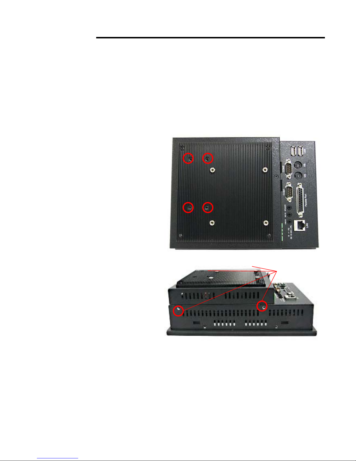
2.1 Removal of Heat pipe module &
Chassis Cover
There are 8 screws to deal with when
enclosing or removing the chassis. Four are
on the heat sink and four on the side of
top-cover.
4 screws at
side of
top-cover
Page 14
EX-96085 User Manual
14
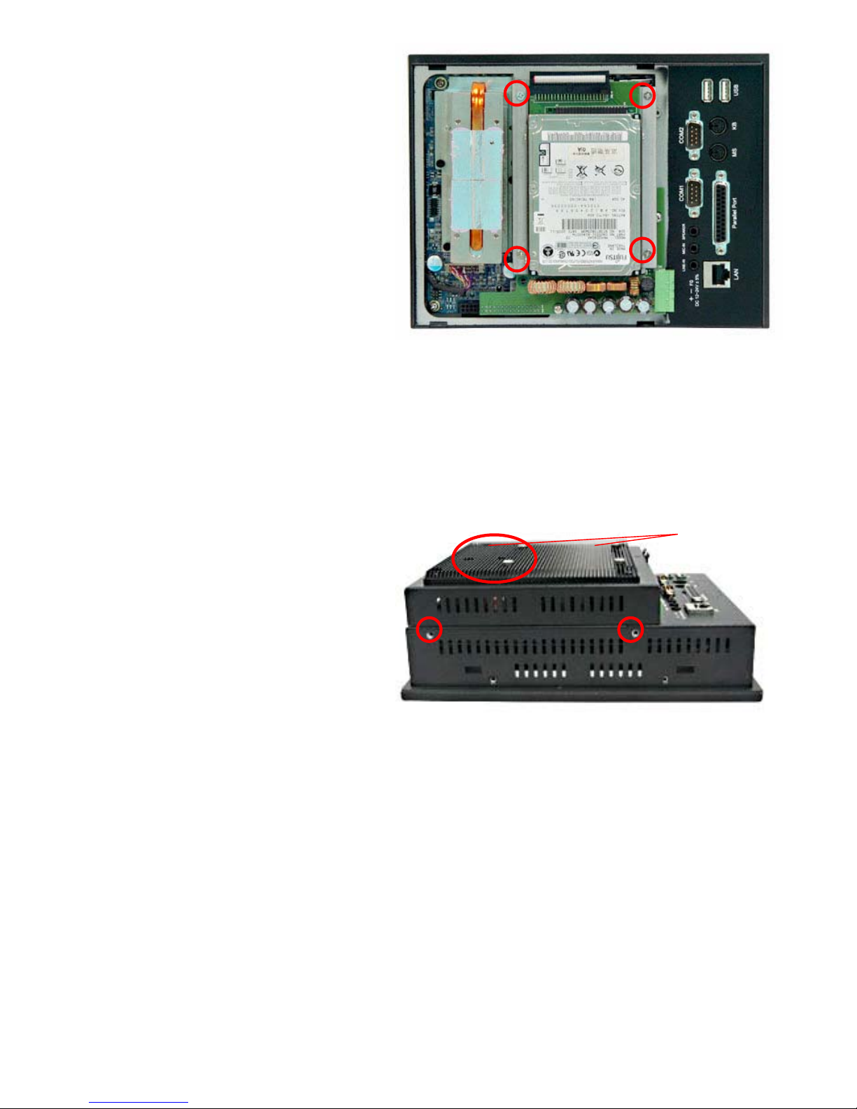
2.2 Removing HDD rack
Remove the HDD rack by loosening the four
screws as circled.
2.3 Closing Chassis
Close the chassis in the same way as it was
opened. Just tighten the 8 screws as circled
and the installation of the EX-96085 is
completely done.
Both of 2
at the right
side
Page 15
EX-96085 User Manual
15
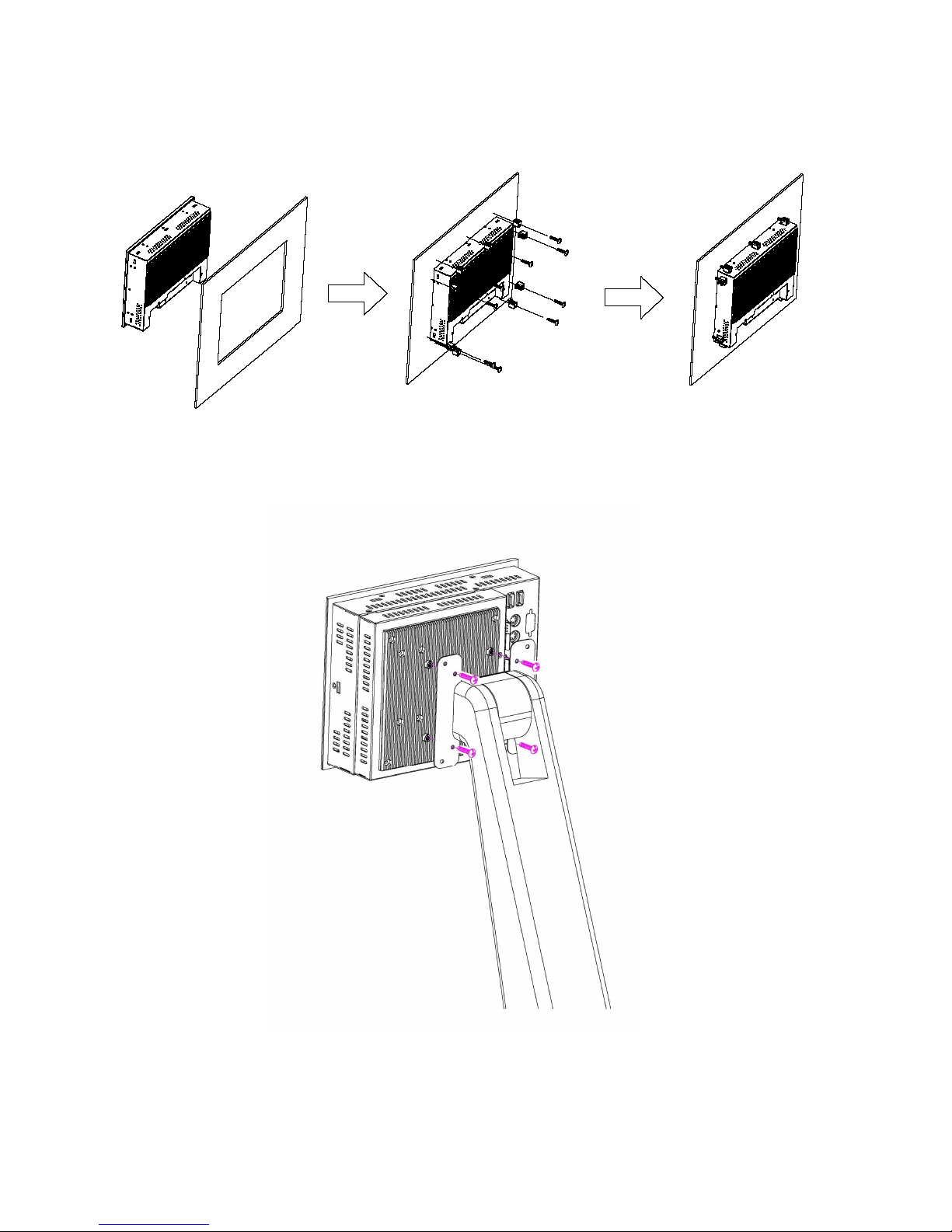
2.4 Panel Mounting
The EX-96085 HMI Controller is designed to be panel-mounted and VESA mounted as shown in
Figure 2.1 and 2.2.
Figure 2.1: Panel-mounting
Figure 2.2: VESA Mount
Page 16

EX-96085 User Manual
16
Chapter 3 Mainboard Configuration
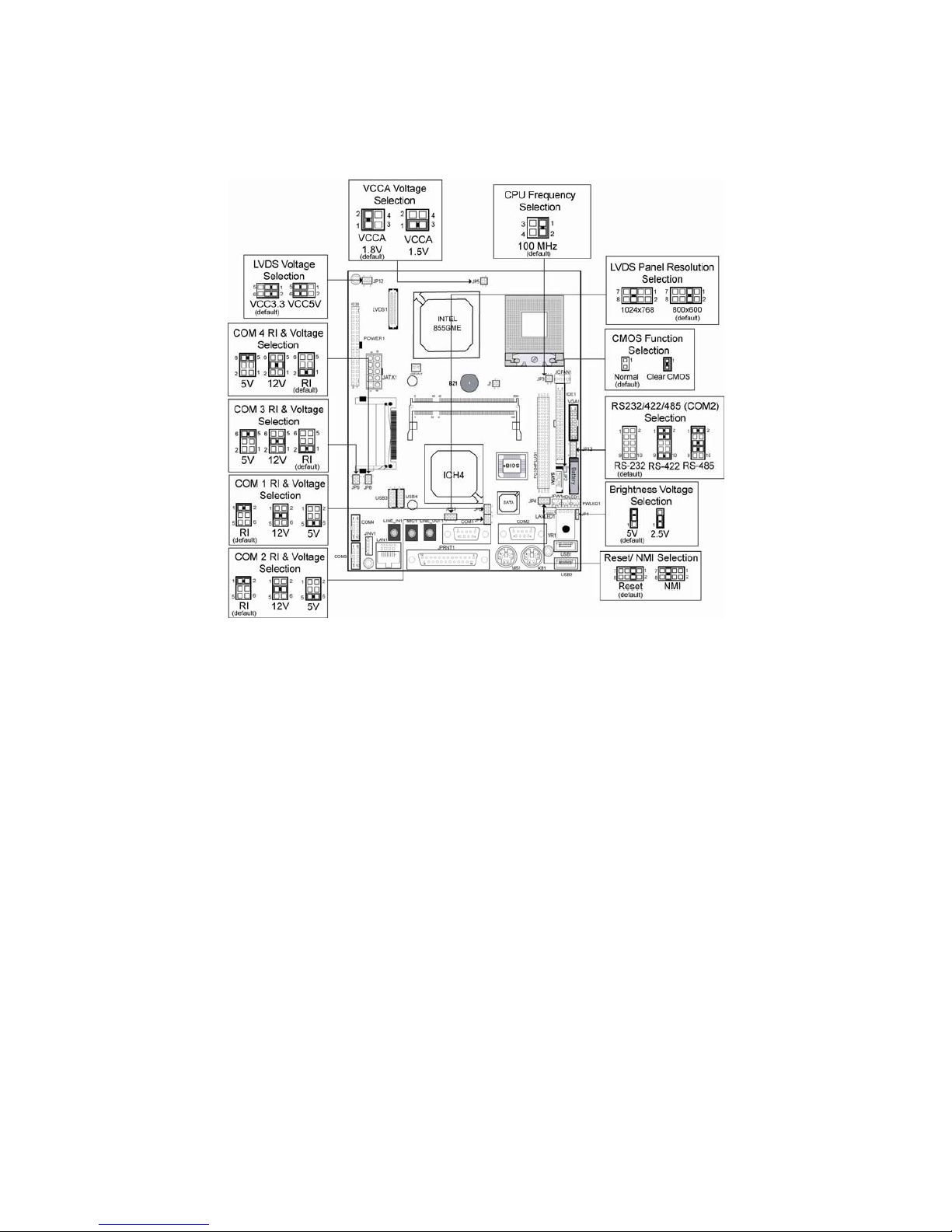
3.1 JUMPER & CONNECTOR QUICK REFERENCE TABLE
COM1 RI & Voltage Selection …………..…………...... JP6
COM2 RI & Voltage Selection ……………………….… JP7
COM3 RI & Voltage Selection ………………………. …JP9
COM4 RI & Voltage Selection ……………………….… JP8
RS232/422/485 (COM2) Selection ..................…..….JP13
Brightness Voltage Selection ……………………..….... JP1
LVDS Voltage Selection ………………………………... JP12
LVDS Panel Resolution Selection …………………….. JP10
CMOS Function Selection …………………………….. .JP2
Watchdog Reset/NMI Selection ………..…………….. .JP4
CPU_VCCA Voltage Selection ……………………….. .JP5
CPU Frequency Selection …………………………….. .JP3
VGA Connector ………………………………………. .VGA1
LVDS Connector ............................................………. .LVDS1
COM Port Connector …………………………………....COM1, COM2
………………………………………....COM3, COM4
Power Connector …………………………………….. .JATX1
Hard Disk Drive Connector …...........................……. IDE1
Printer Connector …………………………………….. JPRNT1
LAN Connector ….....................…....................……… LAN1
LAN LED Connector ……………………………………. LANLED1
Keyboard Connector …………………………………. KB1
PS/2 Mouse Connector …….........................………… MS1
HDD LED Connector ……………………………………HDLED1
Power Button …………………….…………………….JPW1
Power LED Connector ………………………………….PWLED1
USB Connector ………………………………………… USB1, USB2, USB3, USB4
Memory Installation …......................................…… DIMM1
Inverter Connector ……………………………………JINV1
IDE Power Module ……………………………………. POWER1
Compact Flash Connector …………………………….CF1
PC104+ Connector ………………………………….. PC104PLUS1
CPU Fan Connector ……………………………………JCFAN1
System Fan Connector …………………………………JSFAN1
Page 17
EX-96085 User Manual
17
Serial ATA Connector …………………………………. SATA1
Reset & Speaker Connector ………………………….. J1
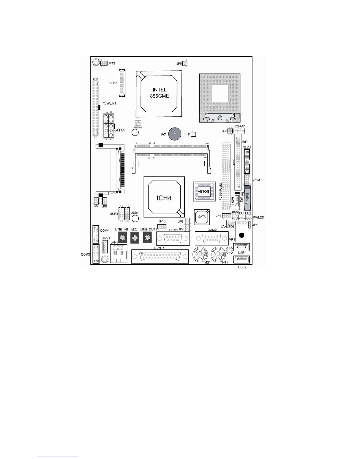
3.2 COMPONENT LOCATIONS
Main Board’s Connector, Jumper and Component locations
Page 18
EX-96085 User Manual
18
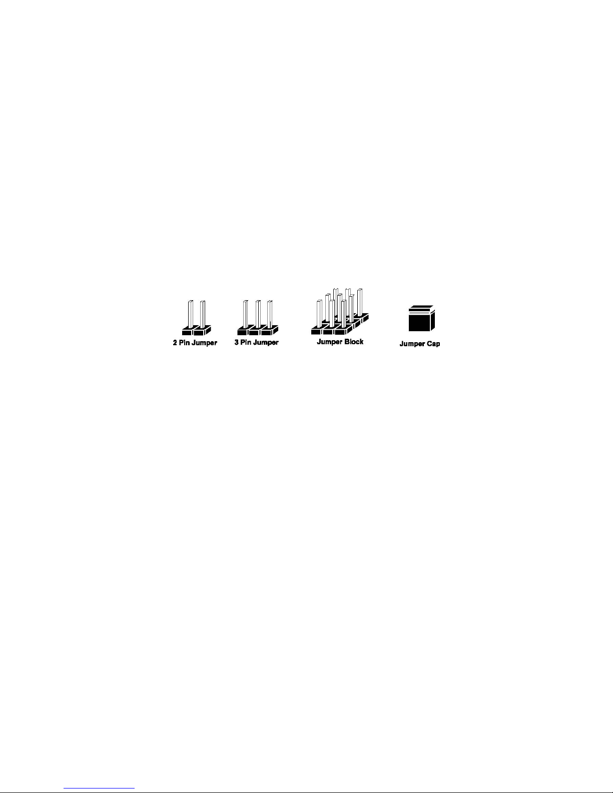
3.3 HOW TO SET THE JUMPERS
You can configure your board by setting the jumpers. Jumper is consists of two or three metal
pins with a plastic base mounted on the card, and by using a small plastic "cap", Also known as
the jumper cap (with a metal contact inside), you are able to connect the pins. So you can set-up
your hardware configuration by "opening" or "closing" pins.
The jumper can be combined into sets that called jumper blocks. When the jumpers are all in the
block, you have to put them together to set up the hardware configuration. The figure below
shows how this looks like.
JUMPERS AND CAPS
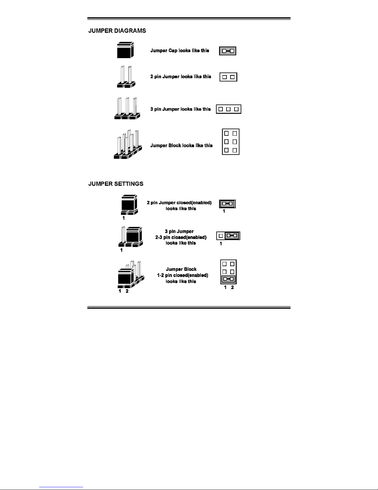
If a jumper has three pins for example, labelled PIN1, PIN2, and PIN3. You can connect PIN1 & PIN2
to create one setting and shorting. You can either connect PIN2 & PIN3 to create another setting. The
same jumper diagrams are applied all through this manual. The figure below shows what the manual
diagrams look and what they represent.
Page 19
EX-96085 User Manual
19
JUMPER DIAGRAMS
Page 20
EX-96085 User Manual
20
JUMPER SETTINGS
Main board Jumper Illustration
3.4 COM 1 RI & VOLTAGE SELECTION
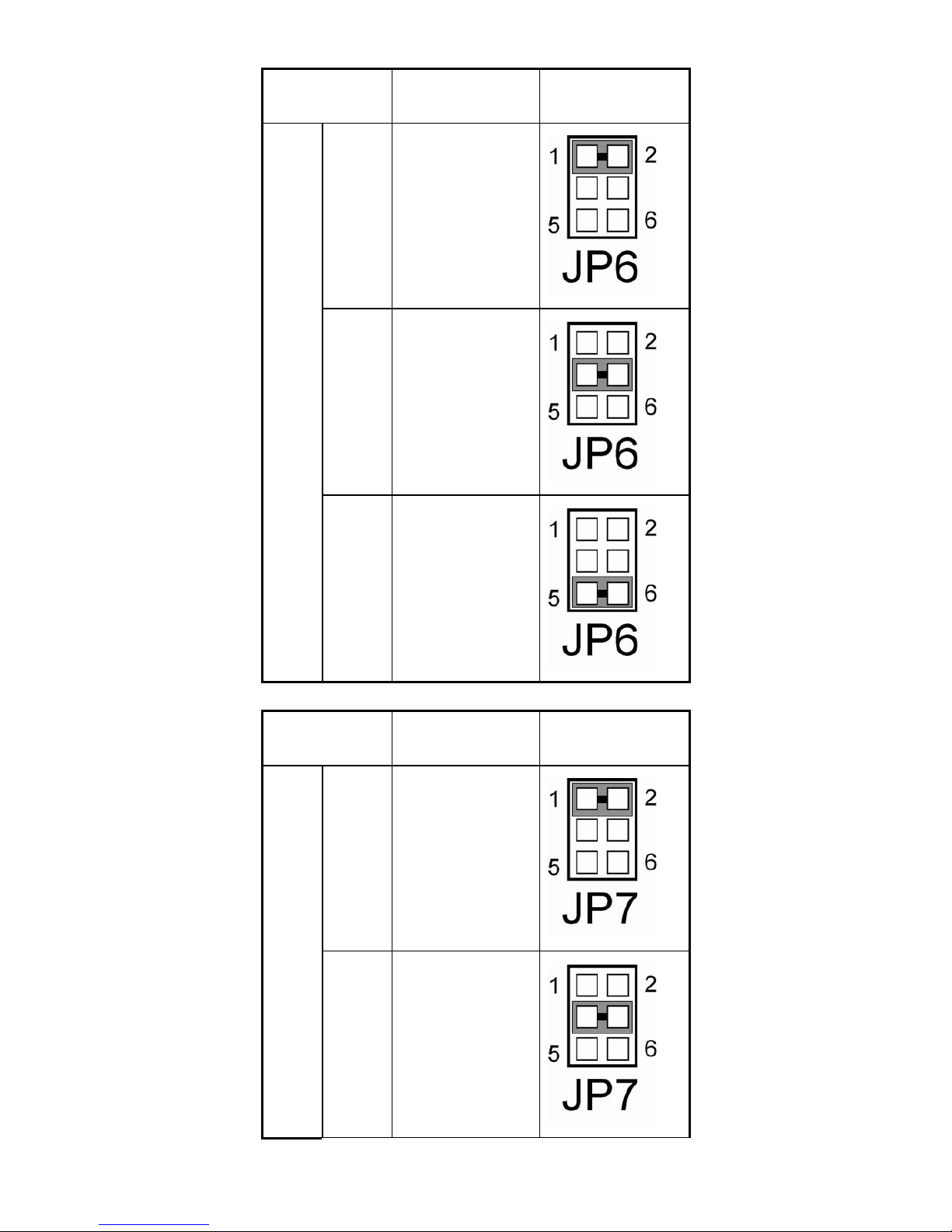
JP6 : COM1 RI & Voltage Selection The selections are as follows:
3-5. COM 2 RI & VOLTAGE SELECTION
JP7 : COM2 RI & Voltage Selection The selections are as follows:
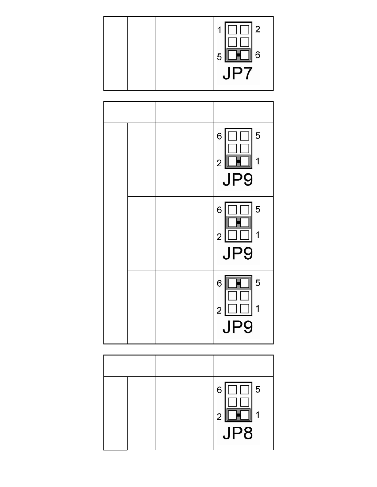
3-6. COM 3 RI & VOLTAGE SELECTION
JP9 : COM3 RI & Voltage Selection The selections are as follows:
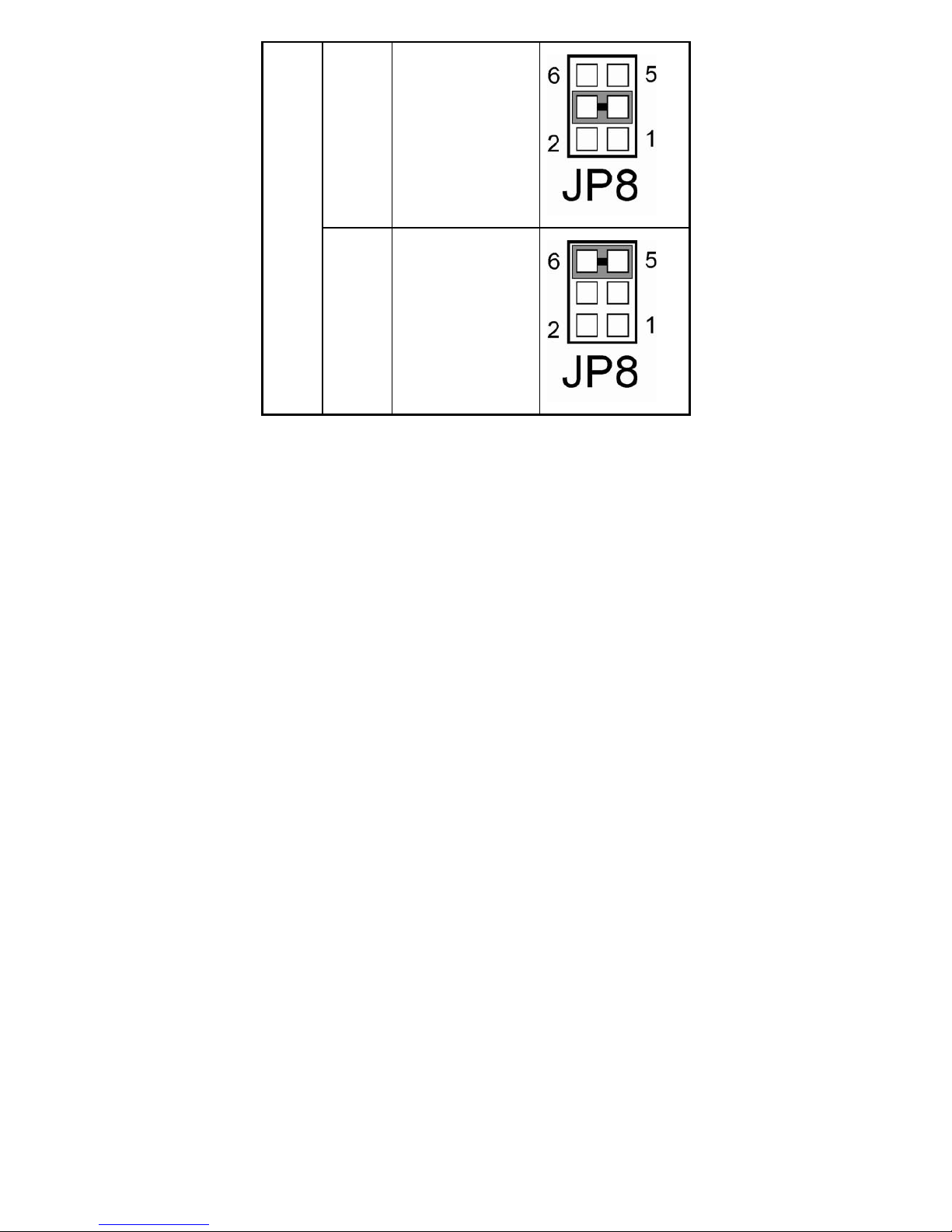
3-7. COM 4 RI & VOLTAGE SELECTION
JP8 : COM4 RI & Voltage Selection The selections are as follows:
Page 21
EX-96085 User Manual
21
SELECTION
JUMPER SETTING
(Pin Closed)
JUMPER
ILLUSTRATION
RI
(default)
1-2
12V
3-4
COM1
5V
5-6
SELECTION
JUMPER SETTING
(Pin Closed)
JUMPER
ILLUSTRATION
RI
(default)
1-2
COM2
12V
3-4
Page 22
EX-96085 User Manual
22
5V
5-6
SELECTION
JUMPER SETTING
(Pin Closed)
JUMPER
ILLUSTRATION
RI
(default)
1-2
12V
3-4
COM3
5V
5-6
SELECTION
JUMPER SETTING
(Pin Closed)
JUMPER
ILLUSTRATION
COM4
RI
(default)
1-2
Page 23
EX-96085 User Manual
23
12V
3-4
5V
5-6
Page 24

EX-96085 User Manual
24
3.8 RS232/422/485 (COM2) SELECTION
JP13 : RS-232/422/485 (COM2) Selection
COM2 is selectable for RS-232, 422, 485 function.
The jumper settings are as follows :
COM 2
FUNCTION
JUMPER
SETTING (pin
closed)
JUMPER ILLUSTRATION
RS-232
(default)
Open
RS-422 1-2, 3-4, 9-10
RS-485 1-2, 5-6, 7-8
Page 25
EX-96085 User Manual
25
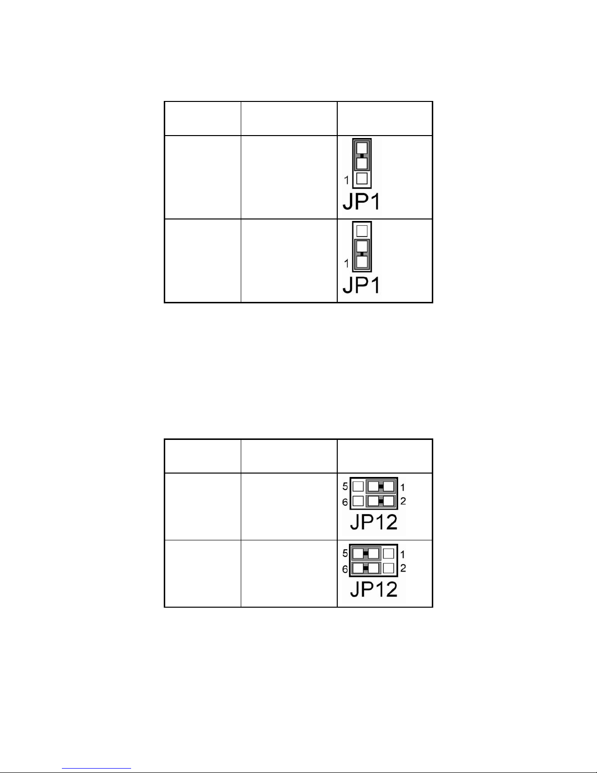
3.9 BRIGHTNESS VOLTAGE SELECTION
JP1: Brightness Voltage Selection The selections are as follows :
SELECTION
JUMPER SETTING
(Pin Closed)
JUMPER
ILLUSTRATION
5V (default)
2-3
2.5V
1-2
3.10 LVDS VOLTAGE SELECTION
JP12: LVDS Voltage Selection
The selections are as follows :
SELECTION
JUMPER SETTING
(Pin Closed)
JUMPER
ILLUSTRATION
VCC 3.3
1-3, 2-4
VCC 5
3-5, 4-6
Page 26

EX-96085 User Manual
26
3.11 LVDS PANEL RESOLUTION SELECTION
JP10 : LVDS Panel Resolution Selection.
The selections are as follows:
FUNCTION
JUMPER SETTING
(pin closed)
JUMPER
ILLUSTRATION
640 x 480 1-2
800 x 600 (10.4”)
(default)
3-4
1024 x 768 (15”) 5-6
1280 x 1024 7-8
3.12 CMOS FUNCTION SELECTION
JP2: CMOS Function Selection The selections are as follows:
FUNCTION
JUMPER
SETTING (pin
closed)
JUMPER
ILLUSTRATION
NORMAL (default) Open
CLEAR CMOS 1-2
Page 27
EX-96085 User Manual
27
To clear CMOS data, user must power-off the computer and set the jumper to “Clear CMOS” as
illustrated above. After five to six seconds, set the jumper back to “Normal” and power-on the
computer.
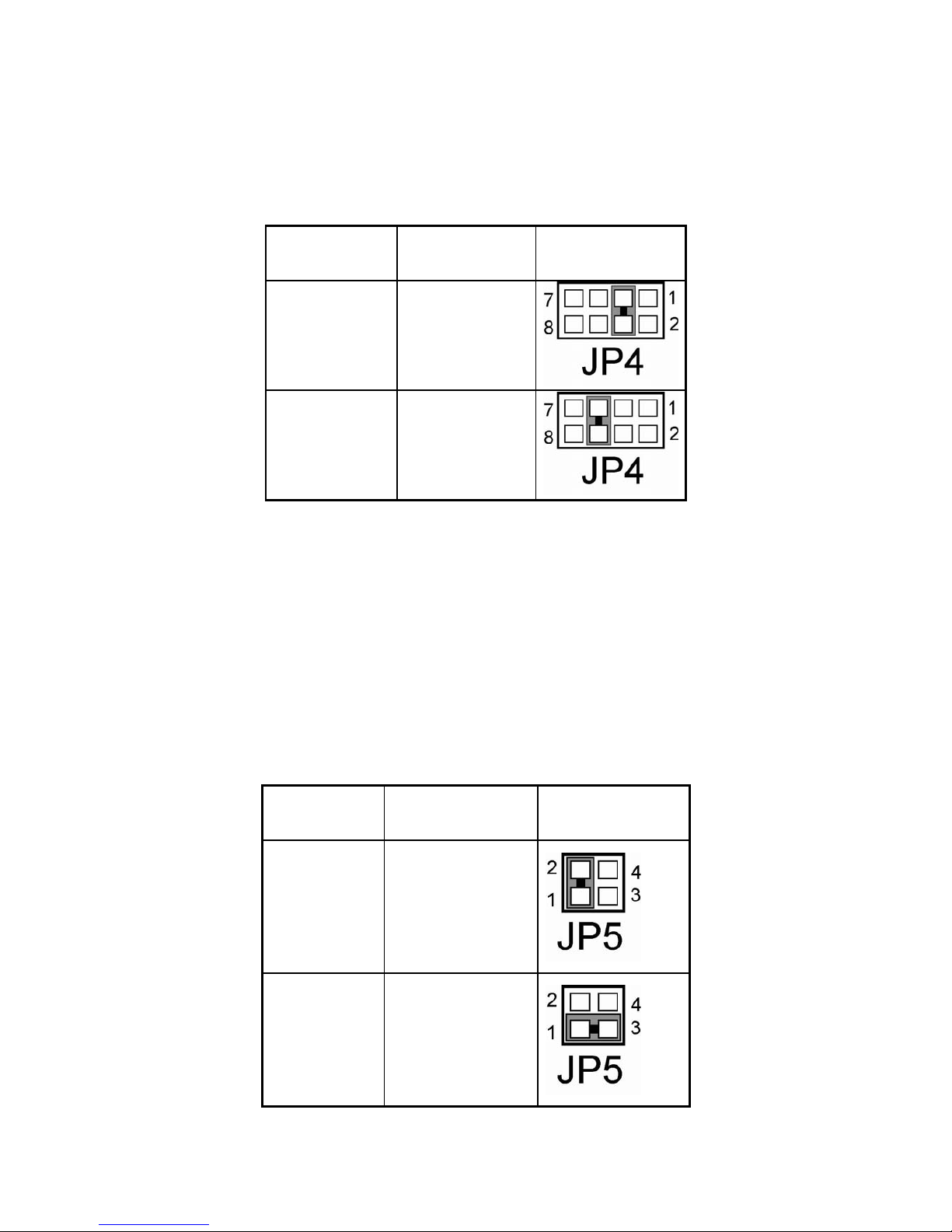
3.13 RESET / NMI SELECTION
JP4 : Reset/NMI/Clear Watchdog Selection The selections are as follows:
FUNCTION JUMPER SETTING
JUMPER
ILLUSTRATION
Reset (default) 3-4
NMI 5-6
User may select to use the Reset or NMI watchdog. NMI, also known as Non-Maskable Interrupt, is
used for serious conditions that demand the processor’s immediate attention, it cannot be ignored by
the system unless it is shut off specifically. To clear NMI command, user should short the “Clear
Watchdog” pin via push button.
3.14 CPU_VCCA VOLTAGE SELECTION
JP5: CPU_VCCA Voltage Selection The selections are as follows :
SELECTION
JUMPER SETTING
(Pin Closed)
JUMPER
ILLUSTRATION
VCCA 1.8V
1-2
VCCA 1.5V
1-3
*** Manufacturing Default: VCCA 1.8V.
Page 28
EX-96085 User Manual
28
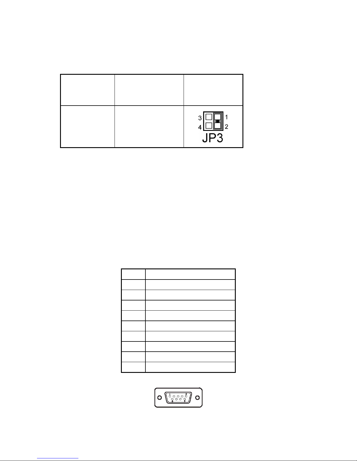
3.15 CPU FREQUENCY SELECTION
JP3: CPU Frequency Selection
The selections are as follows :
SELECTION
JUMPER SETTING
(Pin Closed)
JUMPER
ILLUSTRATION
100 MHz
1-2
*** Manufacturing Default: 100MHz.
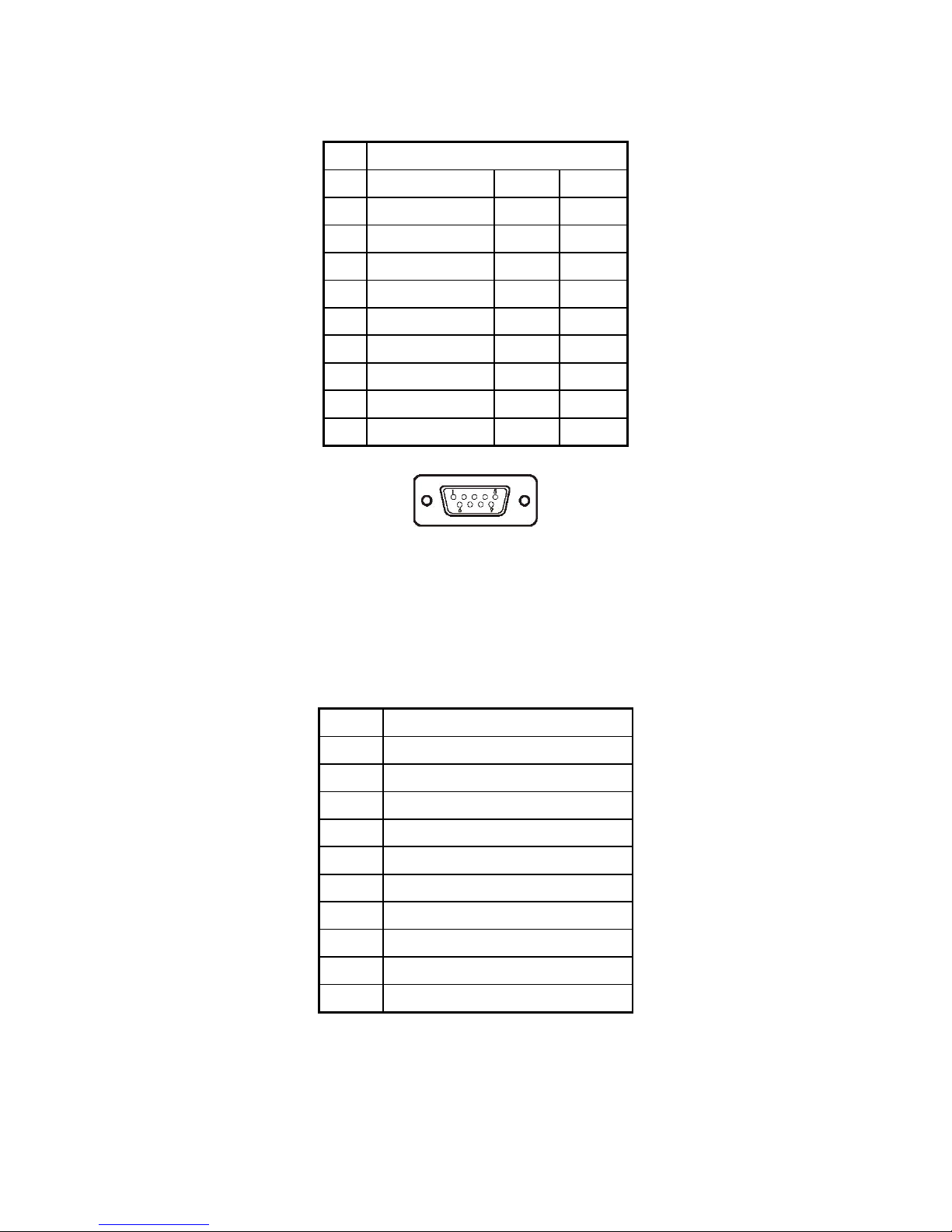
3.16 COM PORT CONNECTOR
There are four COM ports enhanced in this board namely: COM1, COM2, COM3 and COM4. COM1,
COM3 and COM4 are fixed for RS-232, while COM2 is selectable for RS-232/422/485.
COM1 : COM1 Connector
The COM1 Connector assignments are as follows :
PIN ASSIGNMENT
1 DCD1
2 RX1
3 TX1
4 DTR1
5 GND
6 DSR1
7 RTS1
8 CTS1
9 RI1
COM1
Page 29
EX-96085 User Manual
29
COM2 : COM2 Connector
The COM2 Connector assignments are as follows :
PIN ASSIGNMENT
RS-232 RS-422 RS-485
1 DCD2 TX- TX-
2 RX2 TX+ TX+
3 TX2 RX+ RX+
4 DTR2 RX- RX-
5 GND GND GND
6 DSR2 RTS- NC
7 RTS2 RTS+ NC
8 CTS2 CTS+ NC
9
RI2
CTS- NC
COM2
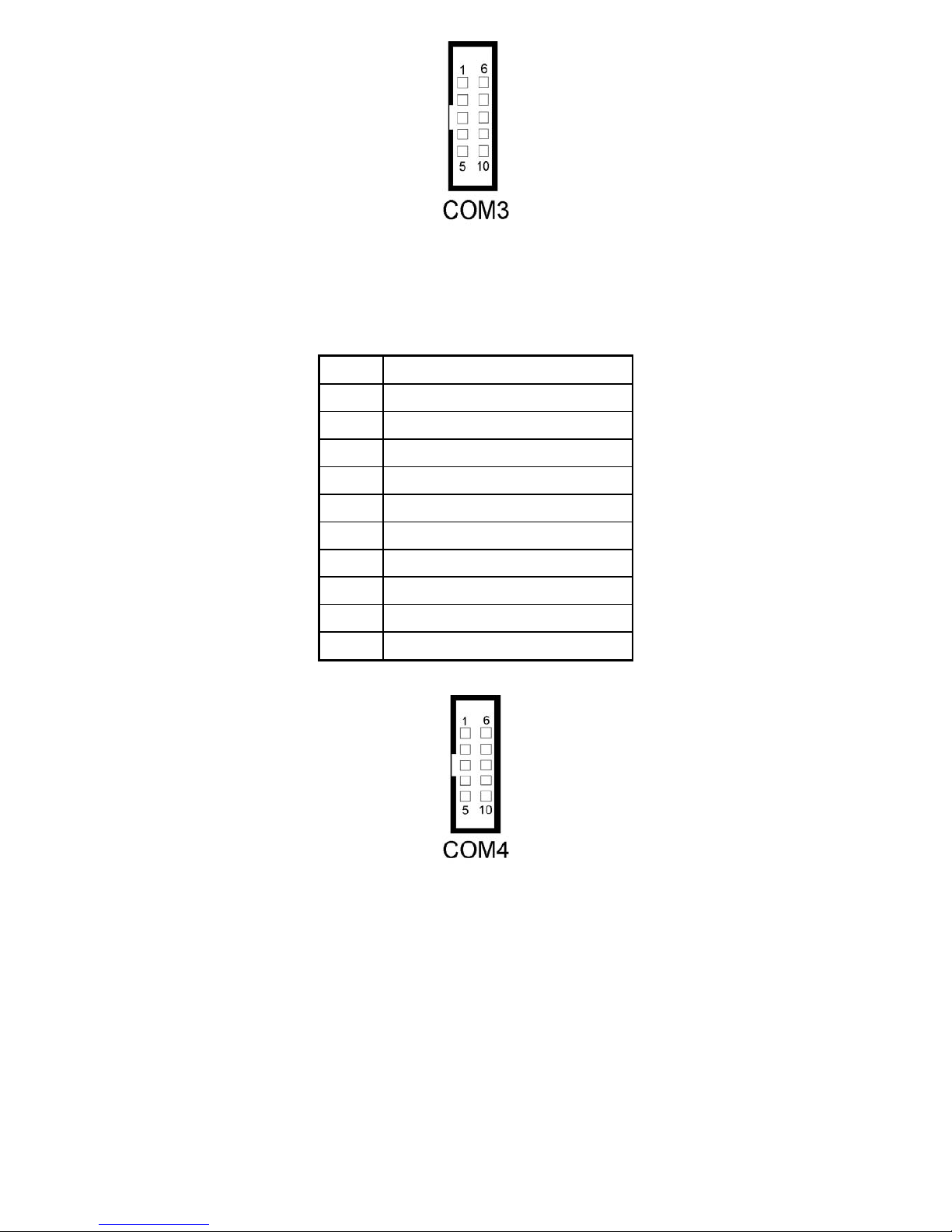
COM3 : COM3 Connector
The pin assignments are as follows :
PIN ASSIGNMENT
1 DCD3
2 RX3
3 TX3
4 DTR3
5 GND
6 DSR3
7 RTS3
8 CTS3
9 RI3
10 NC
Page 30
EX-96085 User Manual
30
COM4 : COM4 Connector
The pin assignments are as follows :
PIN ASSIGNMENT
1 DCD4
2 RX4
3 TX4
4 DTR4
5 GND
6 DSR4
7 RTS4
8 CTS4
9 RI4
10 NC
All COM port’s pin 9 is selectable for RI, +5V or +12V. For more information, please refer to our “2-5
COM RI and Voltage Selection”.
Page 31

EX-96085 User Manual
31
3.17 VGA CONNECTOR
VGA1 : VGA Connector
The pin assignments are as follows:
PIN ASSIGNMENT
1 RED
2 GREEN
3 BLUE
4 NC
5 GND
6 GND
7 GND
8 GND
9 VCC
10 GND
11 NC
12 VGA DDC DATA
13 HSYNC
14 VSYNC
15 VGA DDC CLK
16 NC
Page 32
EX-96085 User Manual
32
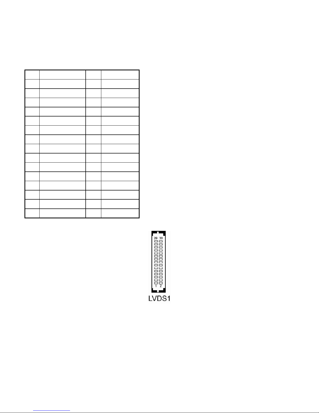
3.18 LVDS CONNECTOR
LVDS1 : LVDS Connector
The pin assignments are as follows :
PIN ASSIGNMENT PIN ASSIGNMENT
1 LVDS_VCC 2 GND
3 ZCN 4 ZCP
5 GND 6 Z2N
7 Z2P 8 GND
9 Z1N 10 Z1P
11 Z3P 12 Z3N
13 Z0P 14 Z0N
15 GND 16 YCP
17 YCN 18 GND
19 Y2P 20 Y2N
21 GND 22 Y1P
23 Y1N 24 GND
25 Y0P 26 Y0N
27 Y3P 28 Y3N
29 LVDS_VCC 30 LVDS_VCC
Page 33
EX-96085 User Manual
33
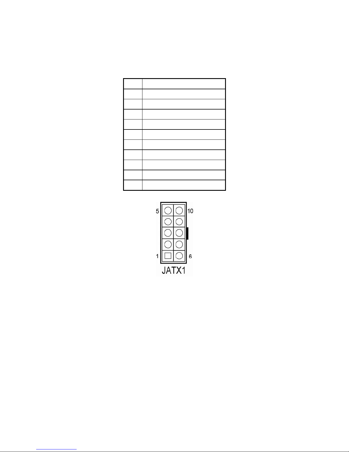
3.19 POWER CONNECTOR
JATX1: Power Connector
The pin assignments are as follows :
PIN ASSIGNMENT
5V
5V
GND
GND
12V
5VSB
5V
GND
PS_ON
-12V
Page 34
EX-96085 User Manual
34
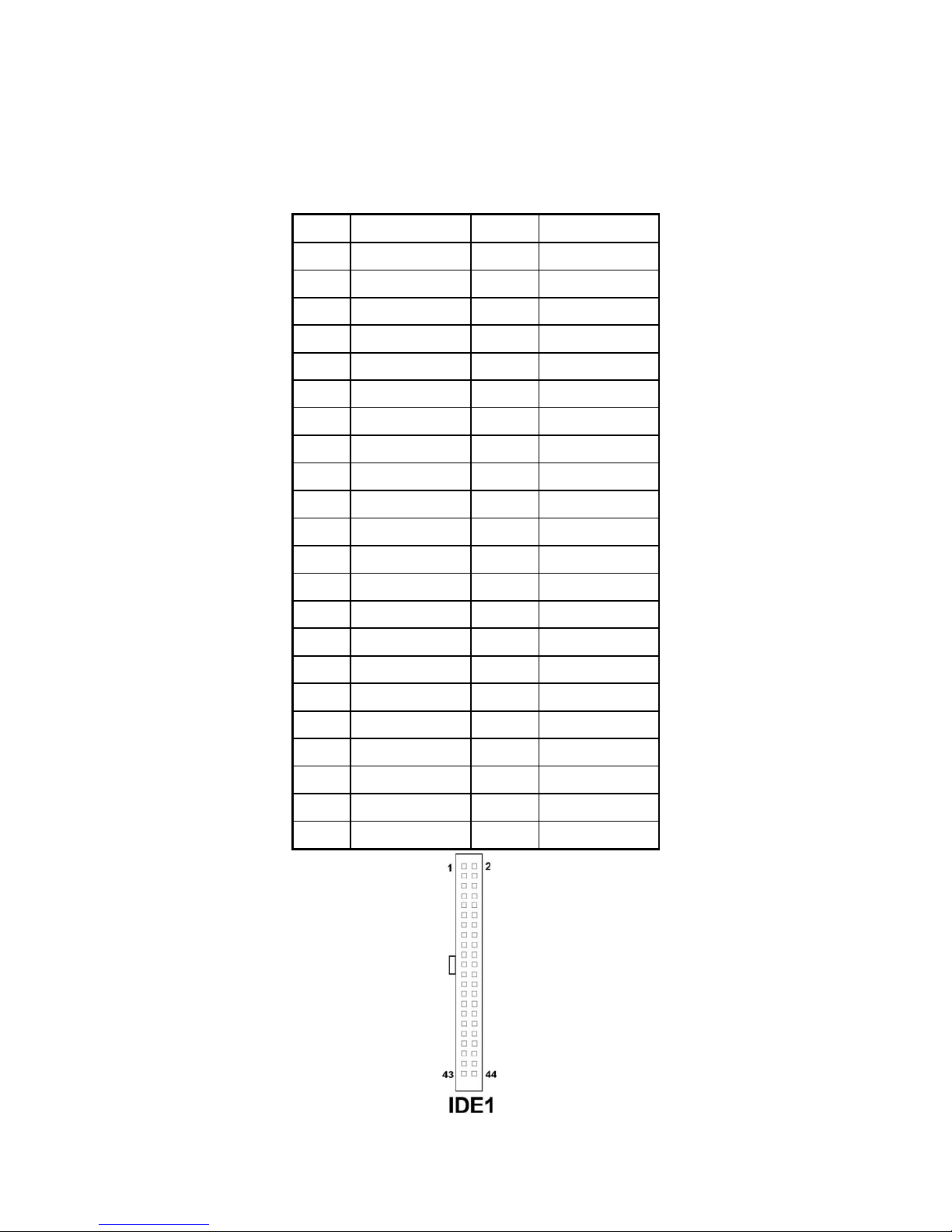
3.20 HARD DISK DRIVE CONNECTOR
IDE1 : Hard Disk Drive Connector
The pin assignments are as follows:
PIN ASSIGNMENT PIN ASSIGNMENT
1 IDERSTJ 2 GND
3 PDD7 4 PDD8
5 PDD6 6
PDD9
7 PDD5 8 PDD10
9 PDD4 10 PDD11
11 PDD3 12 PDD12
13 PDD2 14 PDD13
15 PDD1 16 PDD14
17 PDD0 18 PDD15
19 GND 20 NC
21 DDREQA 22 GND
23 DIOWAJ 24 GND
25 DIORAJ 26 GND
27 HDRDYA 28 PULL LOW
29 DDACKAJ 30 GND
31 IDE_IRQ14 32 NC
33 PDA1 34 PD_80P
35 PDA0 36 PDA2
37 PDCSJ1 38 PDCSJ3
39 HDLEDJ1 40 GND
41 5V 42 5V
43 GND 44 NC
Page 35
EX-96085 User Manual
35
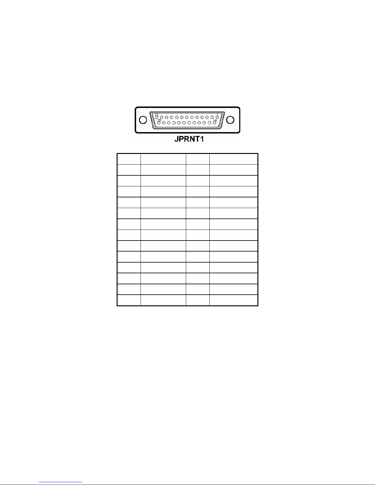
3.21 PRINTER CONNECTOR
JPRNT1 : Printer Connector
As to link the Printer to the card, you need a cable to connect both DB25
connector and parallel port.
The pin assignments are as follows :
PIN ASSIGNMENT PIN ASSIGNMENT
1 STROBE 14 AFDJ
2 PPD0 15 ERRORJ
3 PPD1 16 INITJ
4 PPD2 17 SLINJ
5 PPD3 18 GND
6 PPD4 19 GND
7 PPD5 20 GND
8 PPD6 21 GND
9 PPD7 22 GND
10 ACKJ 23 GND
11 BUSY 24 GND
12 PE 25 GND
13 SLCT
Page 36
EX-96085 User Manual
36
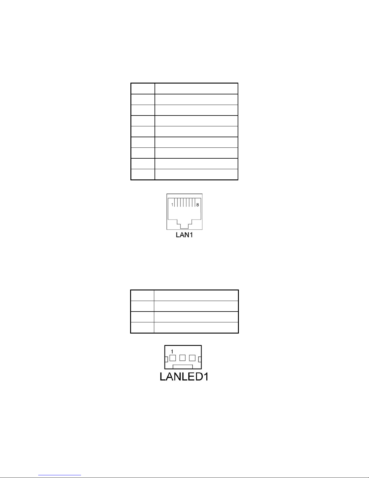
3.22 LAN CONNECTOR
LAN1: LAN Connector.
The pin assignment is as follows :
PIN ASSIGNMENT
1 MDI_0P
2 MDI_0N
3 MDI_1P
4 MDI_2P
5 MDI_2N
6 MDI_1N
7 MDI_3P
8 MDI_3N
3.23 LAN LED CONNECTOR
LANLED1 : LAN LED Connector The pin assignment is as follows :
PIN ASSIGNMENT
1 LED100
2 CONTROL
3 LED1000
Page 37
EX-96085 User Manual
37
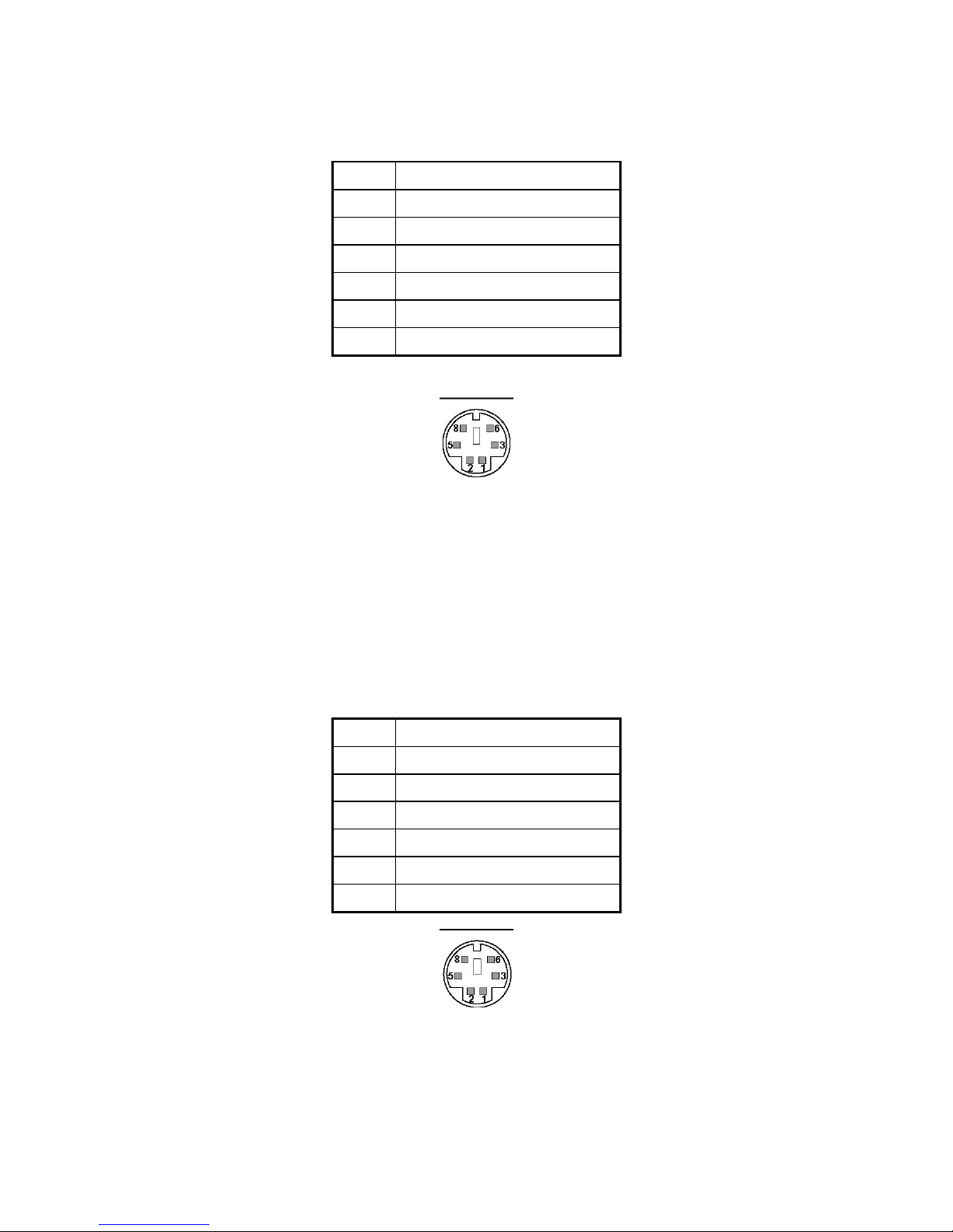
3.24 KEYBOARD CONNECTOR
KB1 : PC/AT Keyboard Connector The pin assignments are as follows :
PIN ASSIGNMENT
1 KB DATA
2 NC
3 GND
5 5VSB
6 KB CLK
8 NC
KB1
3.25 PS/2 MOUSE CONNECTOR
MS1 : PS/2 Mouse Connector
The pin assignments are as follows :
PIN ASSIGNMENT
1 MS DATA
2 NC
3 GND
5 5VSB
6 MS CLK
8 NC
MS1
Page 38
EX-96085 User Manual
38
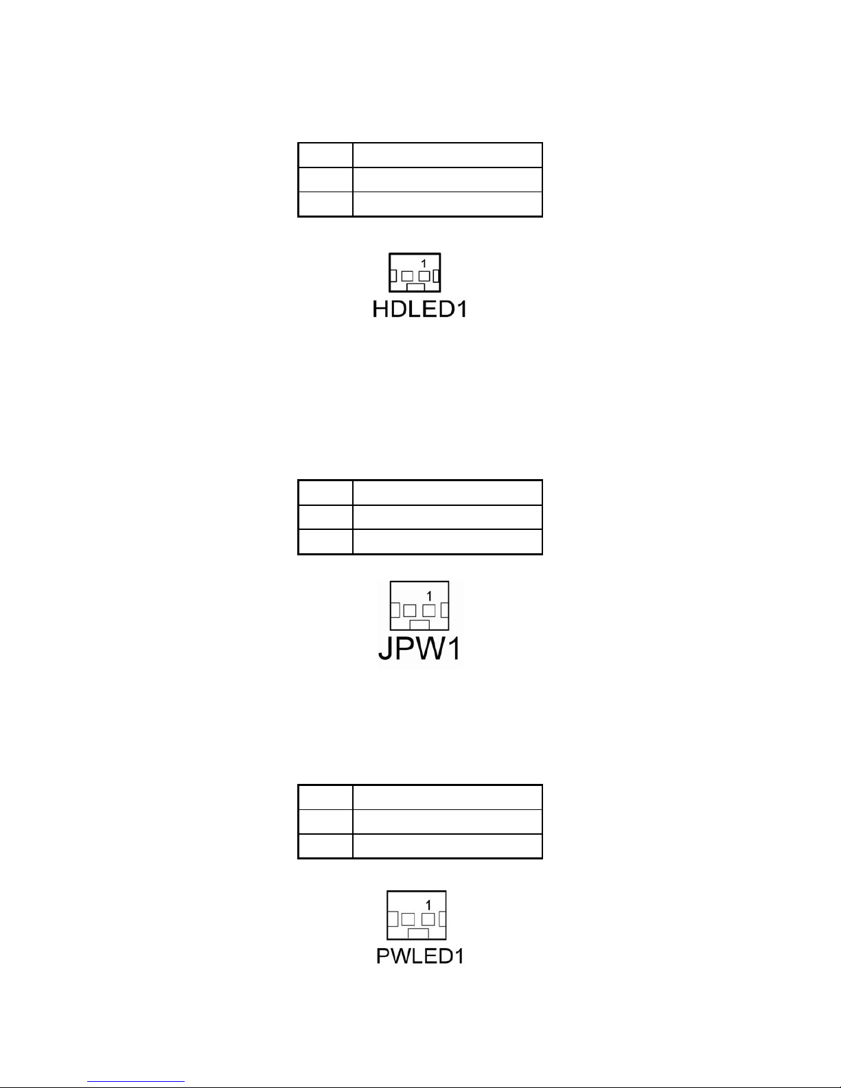
3.26 HDD LED CONNECTOR
HDLED1 : HDD LED Connector The pin assignment is as follows :
PIN ASSIGNMENT
1 HD_LED+
2 HD_LED-
3.27 POWER BUTTON
JPW1 : Power Button
The pin assignments are as follows:
PIN ASSIGNMENT
1 PWR_BN1
2 PWR_BN2
3.28 POWER LED CONNECTOR
PWLED1: Power LED Connector. The pin assignments are as follows :
PIN ASSIGNMENT
1 PW_LED+
2 GND
Page 39
EX-96085 User Manual
39
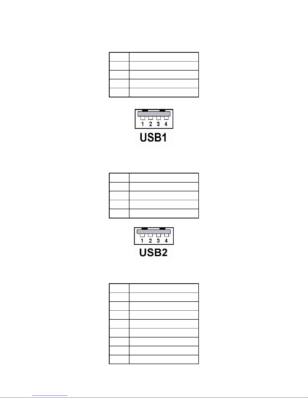
3.29 UNIVERSAL SERIAL BUS CONNECTOR
USB1: Universal Serial Bus Connector. The pin assignments are as follows :
PIN ASSIGNMENT
1 5V_USB0
2 USB0N
3 USB0P
4 GND
USB2: Universal Serial Bus Connector. The pin assignments are as follows :
PIN ASSIGNMENT
1 5V_USB1
2 USB1N
3 USB1P
4 GND
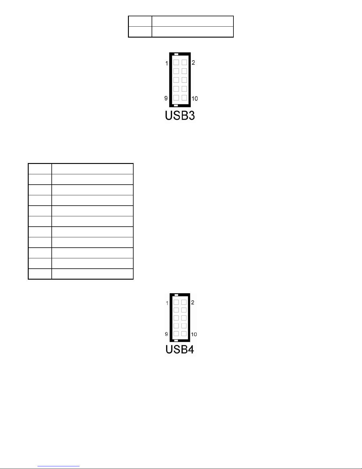
USB3 : Universal Serial Bus Connector. The pin assignments are as follows :
PIN ASSIGNMENT
1 5V_USB2
3 USB2N
5 USB2P
7 GND
9 GND
2 5V_USB3
4 USB3N
6 USB3P
Page 40
EX-96085 User Manual
40
8 GND
10 GND
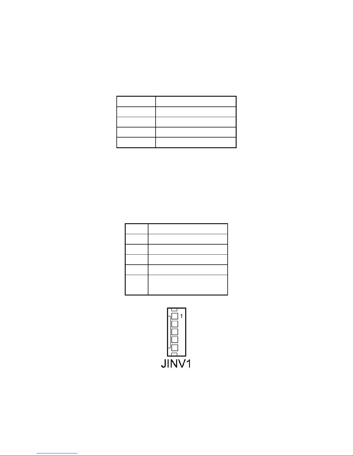
USB4 : Universal Serial Bus Connector. The pin assignments are as follows :
PIN ASSIGNMENT
1 5V_USB4
3 USB4N
5 USB4P
7 GND
9 GND
2 5V_USB5
4 USB5N
6 USB5P
8 GND
10 GND
Page 41
EX-96085 User Manual
41
3.30 MEMORY INSTALLATION
This system is enhanced with 1 DDR DRAM banks, which support up to 1G.
DRAM BANK CONFIGURATION
DIMM 1 TOTAL MEMORY
128M 128MB
256M 256MB
512M 512MB
1G 1G
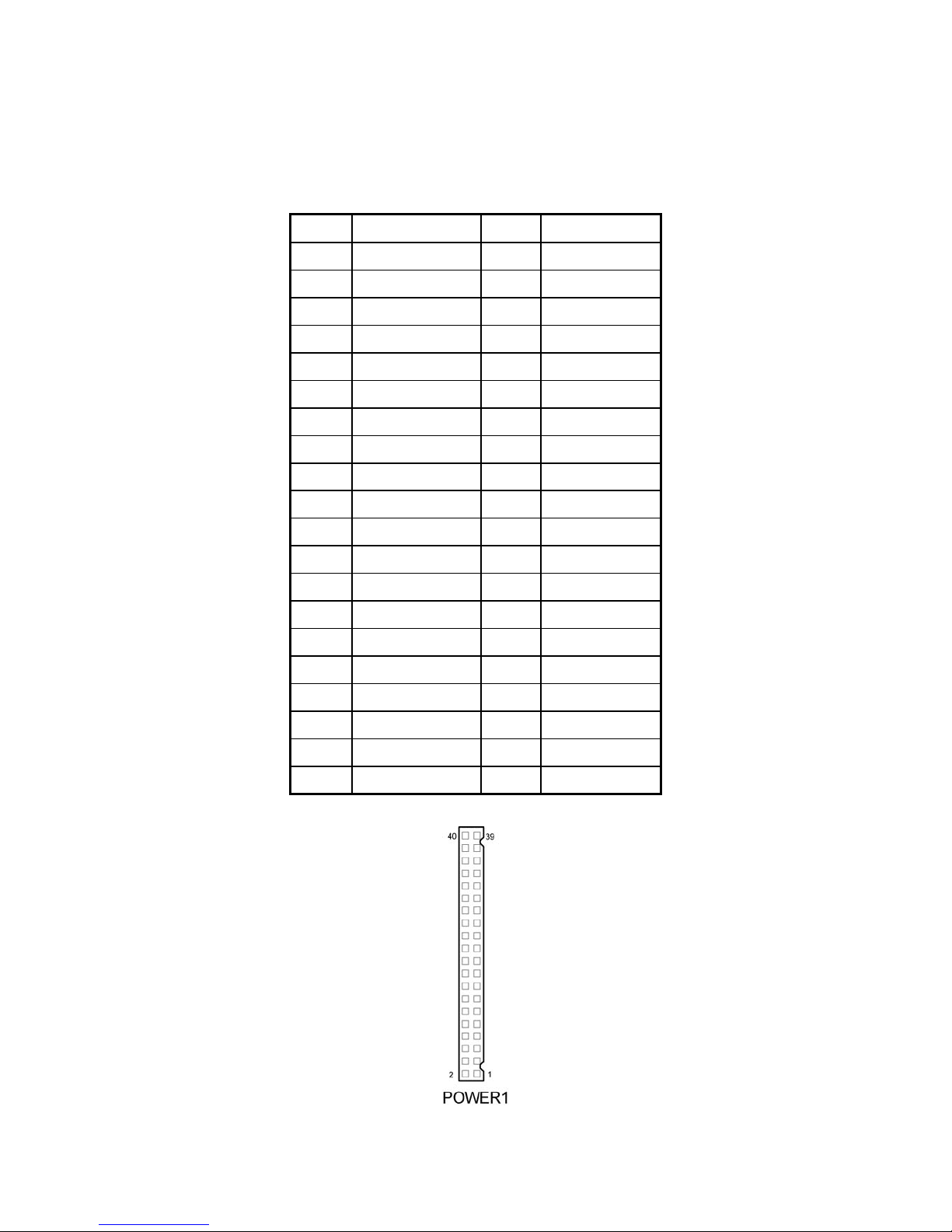
3.31 INVERTER CONNECTOR
JINV1: Inverter Connector.
The pin assignments are as follows :
PIN ASSIGNMENT
1 VCC12
2 GND
3 BRCTR
4 NC
5 ENVEE (Inverter backlight
On/Off control signal)
Page 42
EX-96085 User Manual
42
3.32 POWER MODULE
POWER1 : Power Module.
The pin assignments are as follows :
PIN ASSIGNMENT PIN ASSIGNMENT
1 +5V 2 5VSB
3 +5V 4 5VSB
5 +5V 6 5VSB
7 +5V 8 +5V
9 +5V 10 +5V
11 +5V 12 +5V
13 GND 14 GND
15 GND 16 GND
17 GND 18 GND
19 PS-ON 20 GND
21 NC 22 GND
23 NC 24 GND
25 -12V 26 +12V
27 -12V 28 +12V
29 -12V 30 +12V
31 NC 32 NC
33 NC 34 NC
35 NC 36 NC
37 NC 38 NC
39 NC 40 NC
Page 43

EX-96085 User Manual
43
3.33 COMPACT FLASH CONNECTOR
CF1 : Compact Flash Connector. The pin assignments are as follows :
PIN ASSIGNMENT PIN ASSIGNMENT
1 GND 26 GND
2 D03 27 D11
3 D04 28 D12
4 D05 29 D13
5 D06 30 D14
6 D07 31 D15
7 CSJ1 32 CSJ3
8 GND 33 GND
9 GND 34 SDIORDJ
10 GND 35 SDIOWRJ
11 GND 36 +5V
12 GND 37 IRQ15
13 +5V 38 +5V
14 GND 39 -CSEL
15 GND 40 NC
16 GND 41 RESETJ
17 GND 42 IORDY
18 A02 43 REQ
19 A01 44 ACKJ
20 A00 45 CF_LEDJ
21 D00 46 -PDIAG
22 D01 47 D08
23 D02 48 D09
24 NC 49 D10
25 GND 50 GND
Page 44

EX-96085 User Manual
44
3.34 PCI-104 CONNECTOR
PC104PLUS1 : PCI-104 Connector. The pin assignments are as follows :
A B
C D
PIN
ASSIGNMENT
PIN ASSIGNMENT PIN ASSIGNMENT PIN ASSIGNMENT
A1 GND B1 SERIR C1 +5V D1 AD00
A2 NC B2 AD02 C2 AD01 D2 +5V
A3 AD05 B3 GND C3 AD04 D3 AD03
A4 CBEJ0 B4 AD07 C4 GND D4 AD06
A5 GND B5 AD09 C5 AD08 D5 GND
A6 AD11 B6 NC C6 AD10 D6 M66EN
A7 AD14 B7 AD13 C7 GND D7 AD12
A8 +3.3V B8 CBEJ1 C8 AD15 D8 +3.3V
A9 SERRJ B9 GND C9 NC D9 PAR
A10 GND B10 PERRJ C10 +3.3V D10 SDONE
A11 STOPJ B11 +3.3V C11 LOCKJ D11 GND
A12 +3.3V B12 TRDYJ C12 GND D12 DEVSELJ
A13 FRAMEJ B13 GND C13 IRDYJ D13 +3.3V
A14 GND B14 AD16 C14 +3.3V D14 CBEJ2
A15 AD18 B15 +3.3V C15 AD17 D15 GND
A16 AD21 B16 AD20 C16 GND D16 AD19
A17 +3.3V B17 AD23 C17 AD22 D17 +3.3V
A18 IDSEL0 B18 GND C18 IDSEL1 D18 IDSEL2
A19 AD24 B19 CBEJ3 C19 NC D19 IDSEL3
A20 GND B20 AD26 C20 AD25 D20 GND
A21 AD29 B21 +5V C21 AD28 D21 AD27
A22 +5V B22 AD30 C22 GND D22 AD31
A23 REQJ0 B23 GND C23 REQJ1 D23 NC
A24 GND B24 REQJ2 C24 +5V D24 GNTJ0
A25 GNTJ1 B25 NC C25 GNTJ2 D25 GND
A26 +5V B26 PCLK1 C26 GND D26 PCLK2
A27 PCLK3 B27 +5V C27 PCLK4 D27 GND
A28 GND B28 INTDJ C28 +5V D28 RSTJ
A29 +12V B29 INTAJ C29 INTBJ D29 INTCJ
A30 -12V B30 NC C30 NC D30 GND
Page 45
EX-96085 User Manual
45
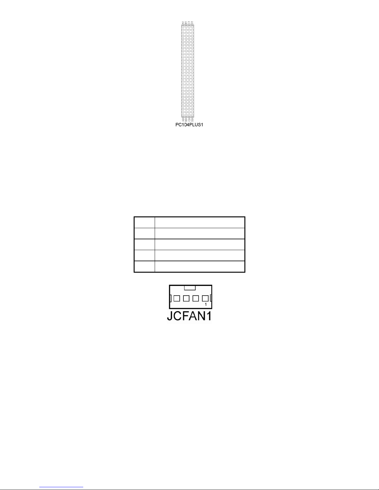
3.35 CPU FAN CONNECTOR
JCFAN1 : CPU Fan Connector
PIN ASSIGNMENT
1 GROUND
2 FAN_VCC12
3 FAN_SPEED OUT
4 FAN_PWM
Page 46
EX-96085 User Manual
46
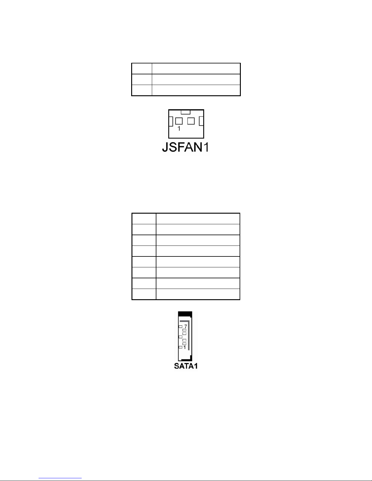
3.36 SYSTEM FAN CONNECTOR
JSFAN1 : System FAN Connector
PIN ASSIGNMENT
1 VCC12
2 GND
3.37 SERIAL ATA CONNECTOR
SATA1 : Serial ATA Connector
PIN ASSIGNMENT
1 GND
2 SATAHDR_TXP0
3 SATAHDR_TXN0
4
GND
5 SATAHDR_RXN0
6 SATAHDR_RXP0
7
GND
Page 47
EX-96085 User Manual
47
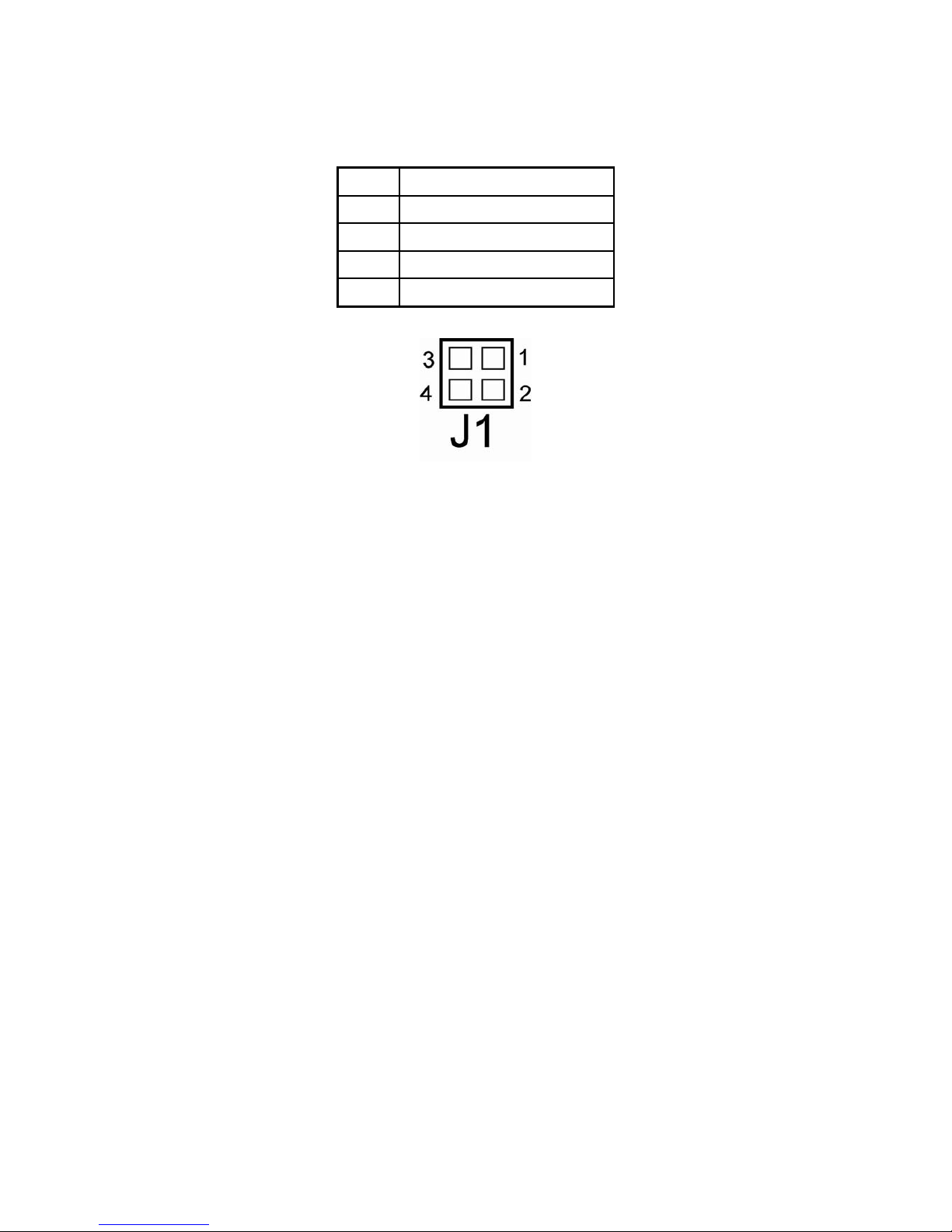
3.38 RESET & SPEAKER CONNECTOR
J1 : Reset and Speaker Connector
PIN ASSIGNMENT
1 SPK_VCC
2 SPK
3 RST_SW
4
GND
Page 48

EX-96085 User Manual
48
Chapter 4 Software Utility
4.1 Introduction to Software Utilities
Enclosed with our EX-96085 package is our driver utility, which may comes in a form of a CD ROM
disc or floppy diskettes. For CD ROM disc user, you will only need some of the files contained in the
CD ROM disc, please kindly refer to the following chart:
Filename (Assume that CD
ROM drive is D:)
Purpose
D:\6xx5\Driver\VGA Intel 855GME For VGA driver
installation
D:\6xx5\Driver\ Flash For flash BIOS update
D:\6xx5\ Driver\ LAN For LAN Driver installation
D:\ 6xx5\Driver\ Sound Realtel ALC202A AC97 For
Sound driver installation
D:\ 6xx5\Driver\ Utility Intel® Chipset Software
Installation Utility For Win98SE,
ME, 2000, XP
D:\ 6xx5\Driver\ USB2.0 USB 2.0 Software Installation
Utility For Win 98SE, 2000, ME,
XP
D:\6xx5\Driver\ SATA Silicon for SATA Driver
installation
4.2 VGA DRIVER UTILITY
The VGA interface embedded with our EX-96085 can support a wide range of display. You can
display CRT, LVDS simultaneously with the same mode.
4.2.1 Installation of VGA Driver:
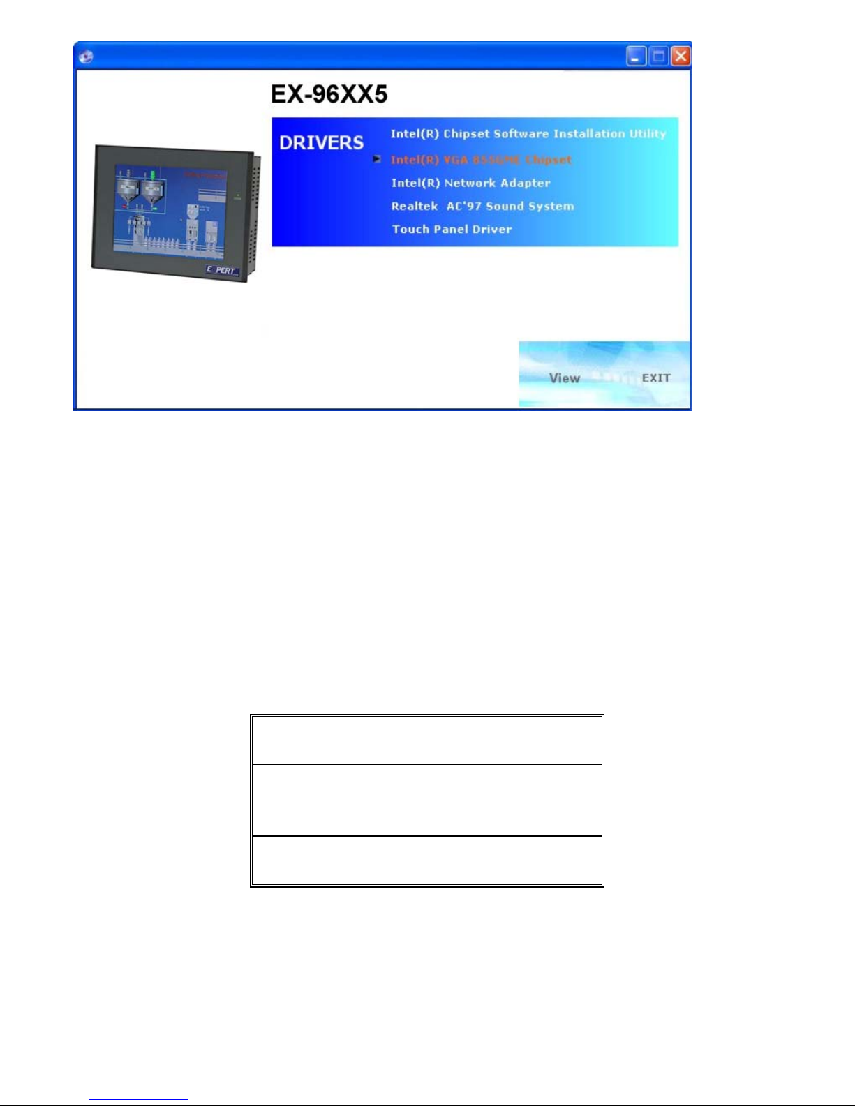
To install the VGA Driver, simply follow the following steps:
Click “intel® VGA 855GME Chipset”
Page 49
EX-96085 User Manual
49
4.3 FLASH BIOS UPDATE
4-3-1. Introduction
Users of EX-96085 can use the program “Awdflash.exe” contained in the Utility Disk for system
BIOS update.
4-3-2. Installation of system BIOS
1 Copy “Awdflash.exe” from Driver Disk to Drive C.
2 Type the path to Awdflash.exe and execute the system BIOS AWDFLASH 7500xxxx.bin
3 The screen will display the table below:
FLASH MEMORY WRITER V7.XX (C) Award
Software 2001 All Rights Reserved
Flash Type -49LF004B File Name to Program:
7500xxxx.bin
Error Message : Do You Want To Save BIOS
(Y/N)
If you want to save up the original BIOS, enter "Y" and press < Enter > . If you choose "N", the
following table will appear on screen.
Page 50

EX-96085 User Manual
50
FLASH MEMORY WRITER V7.XX (C) Award Software
2001 All Rights Reserved
Flash Type - 49LF004B File Name to Program: 7500xxxx.bin
Error Message : Are You Sure To Program (Y/N)
Select "Y", and the BIOS will be renewed. When you are refreshing the BIOS, do not turn off or reset
the system, or you will damage the BIOS. After you have completed all the programming, the screen
displays the table below:
FLASH MEMORY WRITER V7.XX (C) Award Software
2001 All Rights Reserved
Flash Type –49LF004B File Name to Program: 7500xxxx.bin
Verifying Flash Memory – 7FFFF OK Write OK No Update
Write Fail
F1: Reset F10: Exit
Please reset or power off the system, then the Flash BIOS is fully implemented.
4.4 LAN DRIVER UTILITY
4-4-1. Introduction
The EX-96085 Panel PC is enhanced with LAN function that can support various network
adapters. Installation programs for LAN drivers are listed as follows:
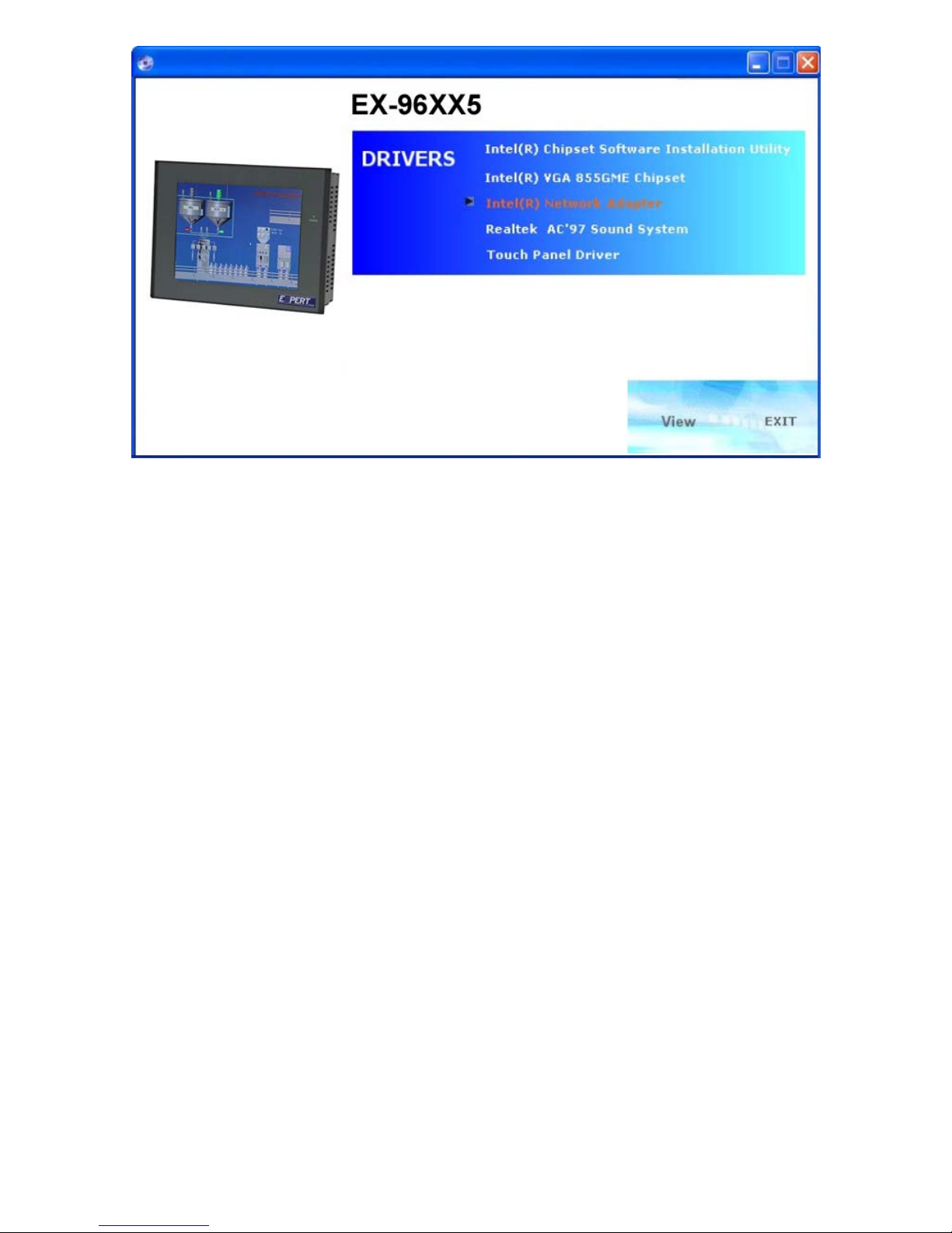
To install the LAN Driver, simply follow the following steps:
Click “intel® Network Adapter”
Page 51
EX-96085 User Manual
51
4.5 SOUND DRIVER UTILITY
4-5-1. Introduction
The Realtek ALC202A sound function enhanced in this system is fully compatible with
Windows 98, Windows NT 4.0, Windows 2000, Windows XP and Linux. Below, you will find
the content of the Sound driver :
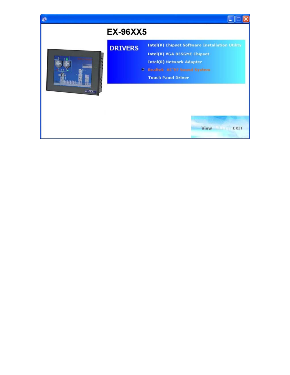
To install the Sound Driver, simply follow the following steps:
Click “Realtek AC97 Sound System”
Page 52
EX-96085 User Manual
52
4.6 INTEL® C HIPSET SOFTWARE INSTALLATION UTILITY
4-6-1. Introduction
The Intel® Chipset Software Installation Utility installs to the target system the Windows* INF
files that outline to the operating system how the chipset components will be configured. This
is needed for the proper functioning of the following features:
-Core PCI and ISAPNP Services -AGP Support -IDE/ATA33/ATA66/ATA100 Storage Support
-USB Support -Identification of Intel® Chipset Components in Device Manager
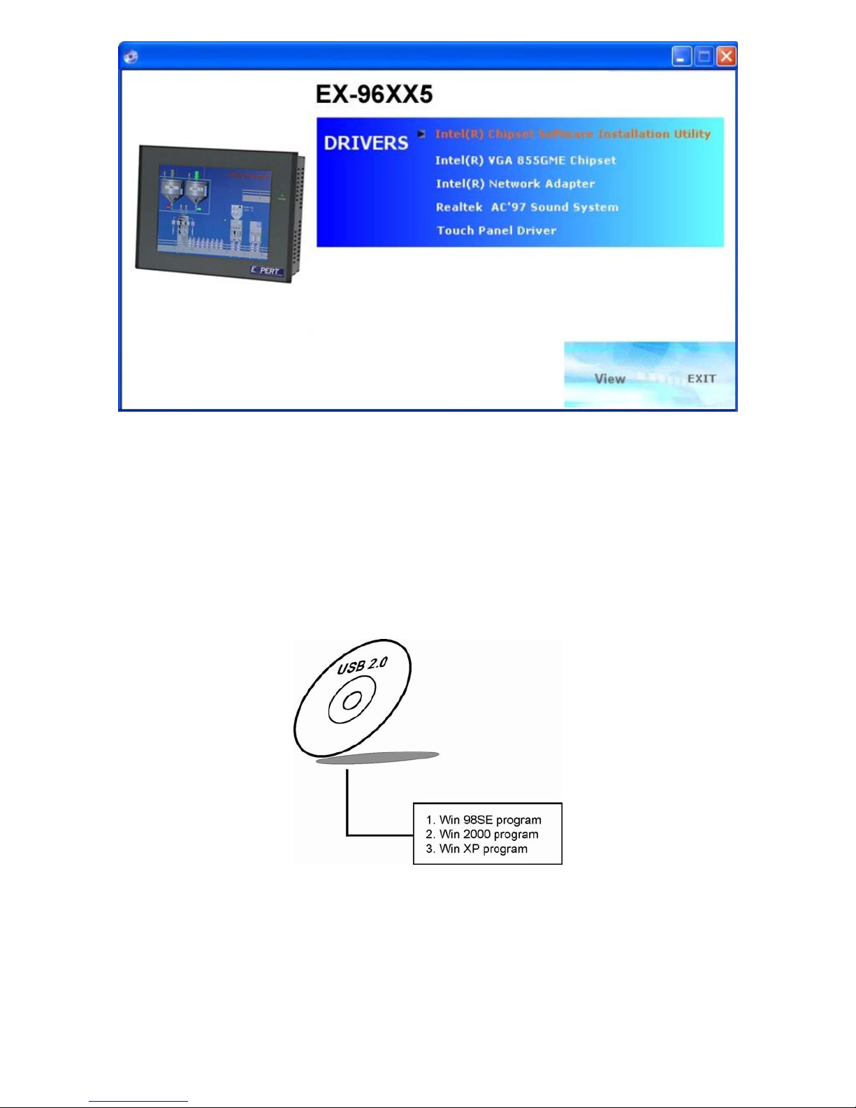
To install the Chipset Driver, simply follow the following steps:
Click “intel® Chipset software installation Utility”
Page 53
EX-96085 User Manual
53
4.7 USB2.0 SOFTWARE INSTALLATION UTILITY
4-7-1. Installation of Utility for Windows 98SE/ 2000/XP
Intel USB 2.0 Enhanced Host Controller driver can only be used on Windows 98SE, Windows
2000 and Windows XP on Intel Desktop boards.
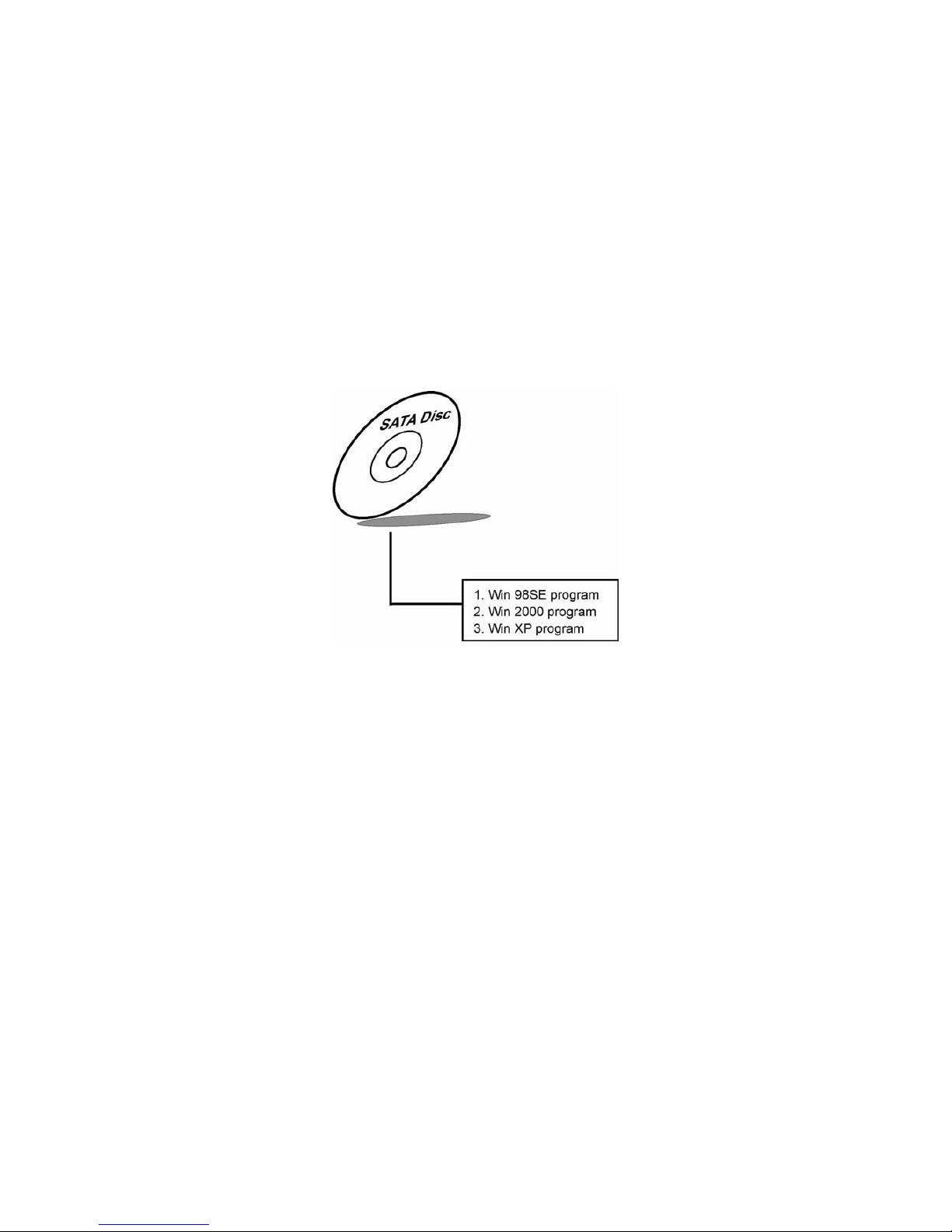
It should be installed right after the OS installation, kindly follow the following steps:
1 Place insert the Utility Disk into Floppy Disk Drive A/B or CD ROM drive.
2 Under Windows 98SE, 2000, and XP system, go to the directory where Utility Disc is located.
3 Start the “System” wizard in control panel. (Click Start/Settings/Control Panel).
4 Select “Hardware” and click “Device Manager ” button.
Page 54
EX-96085 User Manual
54
5 Double Click “USB Root Hub”.
6 Select “Driver”.
7 Click “Install” to install the driver.
8 Follow the instructions on the screen to complete the installation.
9 Click “Finish” after the driver installation is complete.
4.8. SERIAL ATA DRIVER UTILITY
4-8-1. Installation of Utility for Windows 98SE/ 2000/ XP
Silicon Image SATA Sil3512 Controller driver can only be used on Windows 98SE, Windows
2000 and Windows XP on Intel Desktop boards. It should be installed right after the OS
installation, kindly follow the following steps:
1 Please insert the Utility Disk into Floppy Disk Drive A/B or CD ROM drive.
2 Under Windows 98SE, 2000, and XP system, go to the directory where Utility Disc is located.
3 Start the “System” wizard in control panel. (Click Start/Settings/ Control Panel).
4 Select “Hardware” and click “Device Manager” button.
5 Double click “RAID Controller”.
6 Select “Driver”.
7 Click “Si3112r” to install the driver.
8 Follow the instructions on the screen to complete the installation.
9 Click “Finish” after the driver installation is complete.
Page 55
EX-96085 User Manual
55
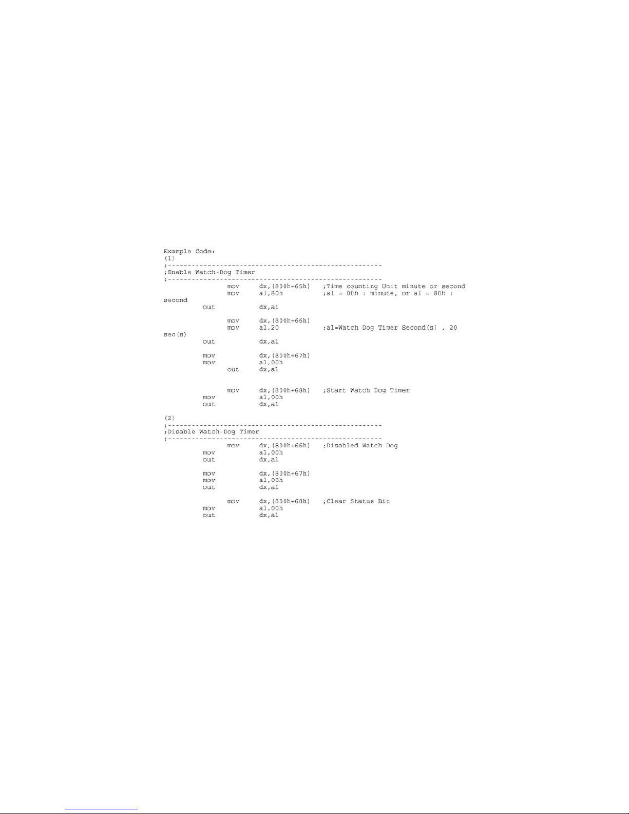
4.9 WATCHDOG TIMER CONFIGURATION
The Watch-dog Timer has a programmable time-out ranging from 1 to 255 minutes with one minute
resolution, or 1 to 255 seconds with 1 second resolution. The units of the WDT timeout value are
selected via bit[7] of the WDT_TIMEOUT register, which is located on I/O Port address 0x865h. The
WDT time-out value is set through the WDT_VAL Runtime register, which is located on I/O Port
address 0x866h. Setting the WDT_VAL register to 0x00 disables the WDT function Setting the
WDT_VAL to any other non-zero value will cause the WDT to reload and begin counting down from
the value loaded. Setting the Register located on I/O address 0x867h and 0x868h as 00h to finish
timer configuration.
Example Program
Page 56
EX-96085 User Manual
56
Chapter 5 AWARD BIOS Setup
5.1 Introduction to Award Bios Setup
This chapter will show you the function of the BIOS in managing the features of your system.
The EX-96085 Panel PC is equipped with the BIOS for system chipset from Award Software Inc.
This page briefly explains the function of the BIOS in managing the special features of your
system. The following pages describe how to use the BIOS for system chipset Setup menu.
Your application programs (such as word processing, spreadsheets, and games) rely on an
operating system such as DOS or OS/2 to manage such things as keyboard, monitor, disk drives,
and memory.
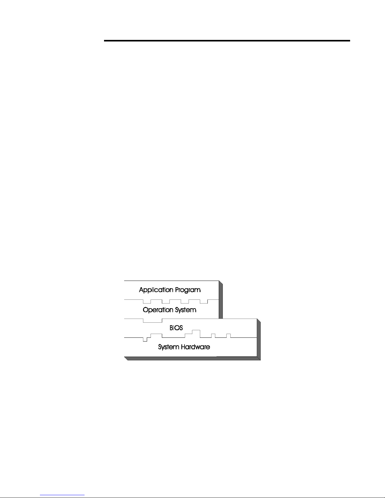
The operating system relies on the BIOS (Basic Input and Output system), a program stored on
a ROM (Read-only Memory) chip, to initialize and configure your computer's hardware. As the
interface between the hardware and the operating system, the BIOS enables you to make basic
changes to your system's hardware without having to write a new operating system.
The following diagram illustrates the interlocking relationships between the system hardware,
BIOS, operating system, and application program:
5.2 ENTERING SETUP
When the system is powered on, the BIOS will enter the Power-On Self
Test (POST) routines and the following message will appear on the lower screen:
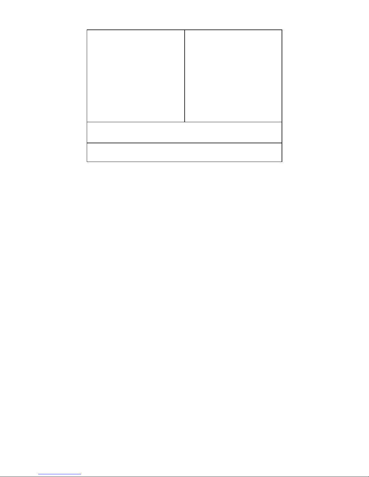
PRESS <DEL> TO ENTER SETUP, ESC TO SKIP MEMORY TEST
As long as this message is present on the screen you may press the <Del> key (the one that
shares the decimal point at the bottom of the number keypad) to access the Setup program. In a
moment, the main menu of the Award SETUP program will appear on the screen:
Page 57
EX-96085 User Manual
57
Phoenix - AwardBIOS CMOS Setup Utility
►Standard CMOS Features
►Advanced BIOS Features
►Advanced Chipset Features
►Integrated Peripherals
►Power Management Setup
►PnP/PCI Configurations
►PC Health Status
►Frequency Control
Load Fail-Safe Defaults
Load Optimized Defaults
Set Supervisor Password
Set User Password
Save & Exit Setup
Exit Without Saving
Esc : Quit ↑↓→← : Select Item
F10 : Save & Exit Setup
Time, Date, Hard Disk Type .…
Setup program initial screen
You may use the cursor the up/down keys to highlight the individual menu items. As you highlight
each item, a brief description of the highlighted selection will appear at the bottom of the screen.
Page 58

EX-96085 User Manual
58
5.3 THE STANDARD CMOS FEATURES
Highlight the 〝STANDARD CMOS FEATURES 〞and press the <ENTER> key and the screen
will display the following table:
Phoenix - AwardBIOS CMOS Setup Utility
Standard CMOS Features
Date (mm:dd:yy)
Time (hh:mm:ss)
Wed, Feb 23 2005
9 : 32 : 52
Item Help
▶ IDE Primary Master
▶ IDE Primary Slave
▶ IDE Secondary Master
▶ IDE Secondary Slave
Video
Halt On
Base Memory
Extended Memory
Total Memory
[ None]
[ None]
[ None]
[ None]
[EGA/VGA]
[All, But Keyboard]
640K
1013760K
1014784K
Menu Level ►
Change the day,
month, year and
century
↑↓→←: Move Enter: Select +/-/PU/PD:Value F10:Save ESC:Exit
F1:General Help
F5: Previous Values F6: Fail-Safe Defaults F7:Optimized
Defaults
CMOS Setup screen
In the above Setup Menu, use the arrow keys to highlight the item and then use the <PgUp> or
<PgDn> keys to select the value you want in each item.
Date: < Month >, < Date > and <Year >. Ranges for each value are in the CMOS Setup Screen, and
the week-day will skip automatically.
Time: < Hour >, < Minute >, and < Second >. Use 24 hour clock format, i.e., for PM numbers, add 12
to the hour. For example: 4: 30 P.M. You should enter the time as 16:30:00.
IDE Primary Master / Slave:
IDE Secondary Master / Slave:
The BIOS can automatically detect the specifications and optimal operating mode of almost all IDE
hard drives. When you select type AUTO for a hard drive, the BIOS detect its specifications during
POST, every time system boots.
If you do not want to select drive type AUTO, other methods of selecting drive type are available:
Page 59

EX-96085 User Manual
59
1.Match the specifications of your installed IDE hard drive(s) with the preprogrammed values for
hard drive types 1 through 45.
2 Select USER and enter values into each drive parameter field.
3.Use the IDE HDD AUTO DETECTION function in Setup.
Here is a brief explanation of drive specifications:
Type: The BIOS contains a table of pre-defined drive types. Each defined drive type has a
specified number of cylinders, number of heads, write precompensation factor, landing zone,
and number of sectors. Drives whose specifications do not accommodate any predefine type
are classified as type USER.
ٛ
•Size: Disk drive capacity (approximate). Note that this size is usually greater than the size of a
ٛ
formatted disk given by a disk-checking program.
ٛ
•Cyls: number of cylinders.
ٛ
•Head: number of heads.
ٛ
•Precomp: write precompensation cylinders.
ٛ
•Landz: landing zone.
ٛ
•Sector: number of sectors.
ٛ
•Mode: Auto, Normal, Large or LBA.
ٛ
Auto: The BIOS automatically determines the optimal mode.
ٛ
•Normal: Maximum number of cylinders, heads, sectors supported are 1024, 16 and 63.
ٛ
•Large: For drives that do not support LBA and have more than 1024 cylinders.
ٛ
•LBA (Logical Block Addressing): During drive accesses, the IDE controller transforms the data
ٛ
address described by sector, head and cylinder number into a physical block address,
ٛ
significantly improving data transfer rates. For drives greater than 1024 cylinders.
DRIVE A AND DRIVE B: Select the type of floppy disk drive installed in your system. The available
options are 360KB 5.25in, 1.2KB 5.25in, 720KB 3.5in, 1.44MB 3.5in, 2.88MB 3.5in and None.
VIDEO:
This category selects the type of video adapter used for the primary system monitor. Although
secondary monitors are supported, you do not have to select the type in Setup. Available Options
are as follows:
EGA/VGA Enhanced Graphics Adapter/Video
Graphics Array. For EGA, VGA, SEGA,
SVGA or PGA monitor adapters.
CGA 40
Color Graphics Adapter, power up in 40
column mode.
CGA 80
Color Graphics Adapter, power up in 80
column mode.
MONO Monochrome adapter, includes high
Page 60

EX-96085 User Manual
60
resolution monochrome adapters.
HALT ON: This category allows user to choose whether the computer will stop if an error is detected
during power up. Available options are “All errors”, “No errors”, “All, But keyboard”, “All, But
Diskette”, and “All But Disk/Key”.
BASE MEMORY:
Displays the amount of conventional memory detected during boot up.
EXTENDED MEMORY:
Displays the amount of extended memory detected during boot up.
TOTAL MEMORY:
Displays the total memory available in the system.
HARD DISK ATTRIBUTES:
Type Cylinde
rs
Hea
ds
V-P
comp
LZone Sect Capacity
1 306 4 128 305 17 10
2 615 4 300 615 17 20
3 615 6 300 615 17 30
4 940 8 512 940 17 62
5 940 6 512 940 17 46
6 615 4 65535 615 17 20
7 642 8 256 511 17 30
8 733 5 65535 733 17 30
9 900 15 65535 901 17 112
10 820 3 65535 820 17 20
11 855 5 65535 855 17 35
12 855 7 65535 855 17 49
13 306 8 128 319 17 20
14 733 7 65535 733 17 42
15 000 0 0000 000 00 00
16 612 4 0000 663 17 20
17 977 5 300 977 17 40
18 977 7 65535 977 17 56
19 1024 7 512 1023 17 59
20 733 5 300 732 17 30
21 733 7 300 732 17 42
22 733 5 300 733 17 30
23 306 4 0000 336 17 10
Page 61

EX-96085 User Manual
61
24 977 5 65535 976 17 40
25 1024 9 65535 1023 17 76
26 1224 7 65535 1223 17 71
27 1224 11 65535 1223 17 111
28 1224 15 65535 1223 17 152
29 1024 8 65535 1023 17 68
30 1024 11 65535 1023 17 93
31 918 11 65535 1023 17 83
32 925 9 65535 926 17 69
33 1024 10 65535 1023 17 85
34 1024 12 65535 1023 17 102
35 1024 13 65535 1023 17 110
36 1024 14 65535 1023 17 119
37 1024 2 65535 1023 17 17
38 1024 16 65535 1023 17 136
39 918 15 65535 1023 17 114
40 820 6 65535 820 17 40
41 1024 5 65535 1023 17 42
42 1024 5 65535 1023 26 65
43 809 6 65535 852 17 40
44 809 6 65535 852 26 61
45 776 8 65335 775 33 100
47 AUTO
Award Hard Disk Type Table
Page 62

EX-96085 User Manual
62
5.4 THE ADVANCED BIOS FEATURES
Choose the 〝ADVANCED BIOS FEATURES〞in the main menu, the screen shown as below.
Phoenix - AwardBIOS CMOS Setup Utility
Advanced BIOS Features
Item Help
Virus Warning
CPU L1 & L2 Cache
CPU L3 Cache
Quick Power On Self Test
First Boot Device
Second Boot Device
Boot Up Floppy Seek
Boot Up NumLock Status
Typematic Rate Setting
x Typematic Rate (Chars/Sec)
x Typematic Delay (Msec)
Security Option
[Enabled]
[Enabled]
[Enabled]
[Enabled]
[SATA/SCSI]
[HDD-0]
[Enabled]
[On]
[Disabled]
6
250
[Setup]
Menu Level ►
↑↓→←: Move Enter: Select +/-/PU/PD:Value F10:Save ESC:Exit
F1:General Help F5: Previous Values F6: Fail-Safe Defaults
F7:Optimized Defaults
BIOS Features Setup Screen
The “BIOS FEATURES SETUP” allow you to configure your system for basic operation. The user
can select the system’s default speed, boot-up sequence, keyboard operation, shadowing and
security.
A brief introduction of each setting is given below.
Virus Warning: Allows you to choose the VIRUS warning feature for IDE Hard Disk boot sector
protection. If this function is enabled and someone attempt to write data into this area, BIOS will
show a warning message on screen and alarm beep.
CPU L1 & L2 CACHE:
This item allows you to enable L1 & L2 cache.
QUICK POWER ON SELF-TEST: This item allows you to speed up Power On Self Test (POST) after
power-up the computer. When enabled, the BIOS will shorten or skip some check items during
POST.
Page 63

EX-96085 User Manual
63
FIRST/SECOND/BOOT DEVICE: The BIOS attempt to load the operating system from the devices in
the sequence selected in these items.
BOOT UP FLOPPY SEEK: You may enable / disable this item to define whether the system will look
for a floppy disk drive to boot at power-on, or proceed directly to the hard disk drive.
BOOT UP NUMLOCK STATUS:
Select power on state for NumLock.
TYPEMATIC RATE SETTING: Enable this item if you wish to be able to configure the characteristics
of your keyboard. Typematic refers to the way in which characters are entered repeatedly if a key
is held down. For example, if you press and hold down the "A" key, the letter "a" will repeatedly
appear on your screen on your screen until you release the key. When enabled, the typematic rate
and typematic delay can be selected.
TYPEMATIC RATE (CHARS/SEC): This item sets the number of times a second to repeat a key
stroke when you hold the key down.
TYPEMATIC DELAY (MSEC): The item sets the delay time after the key is held down before it begins
to repeat the keystroke.
SECURITY OPTION:
This category allows you to limit access to the system and Setup, or just to
Setup.
System
The system will not boot and access to Setup will be
denied if the correct password is not entered at the
prompt.
Setup
The system will boot, but access to Setup will be
denied if the correct password is not entered at the
prompt.
To disable security, select PASSWORD SETTING at Main Menu and then you will be asked to
enter password. Do not type anything and just press <Enter>, it will disable security. Once the
security is disabled, the system will boot and you can enter Setup freely.
Page 64

EX-96085 User Manual
64
5.5 ADVANCED CHIPSET FEATURES
Choose the 〝ADVANCED CHIPSET FEATURES 〞from the main menu, the screen shown as
below.
Phoenix - AwardBIOS CMOS Setup Utility
Advanced Chipset Features
Item Help
DRAM Timing Selectable
X CAS Latency Time
Active to Precharge Delay
X DRAM RAS# to CAS# Delay
X DRAM RAS# Precharge
DRAM Data Integrity Mode
System BIOS Cacheable
Video BIOS Cacheable
Memory Hole At 15M-16M
Delayed Transaction
AGP Aperture Size (MB)
** VGA Setting **
On-Chip VGA
On-Chip Frame Buffer Size
Boot Display
PCI SERR# NMI
[By SPD]
[2.5]
[7]
[3]
[3]
[Non-ECC]
[Enabled]
[Disabled]
[Enabled]
[Enabled]
[64]
[Enabled]
[32MB]
[CRT+LFP]
[Disabled]
Menu Level ►
↑↓→←: Move Enter: Select +/-/PU/PD:Value F10:Save ESC:Exit
F1:General Help
F5: Previous Values F6: Fail-Safe Defaults F7:Optimized Defaults
Chipset Features Setup Screen
This parameter allows you to configure the system based on the specific features of the installed
chipset. The chipset manages bus speed and access to system memory resources, such as DRAM
and the external cache.
It also coordinates communications between conventional ISA bus and the PCI bus. It must be stated
that these items should never need to be altered. The default settings have been chosen because
they provide the best operating conditions for the system. The only time you might consider making
any changes would be if you discovered that data was being lost while using your system.
Page 65

EX-96085 User Manual
65
DRAM TIMEING SELECTABLE:
The value in this field depends on performance parameters of the installed memory chips
(DRAM). Do not change the value from the factory setting unless you install new memory that has
a different performance rating than the original DRAMs.
CAS LATENCY TIME:
When synchronous DRAM is installed, the number of clock cycles of CAS latency depends on
the DRAM timing.
DRAM RAS# TO CAS# DELAY:
This item let you insert a timing delay between the CAS and RAS strobe signals, used when
DRAM is written to, read from, or refreshed. Fast gives faster performance; and Slow gives more
stable performance. This field applies only when synchronous DRAM is installed in the system.
The choices are 2 and 3.
DRAM RAS# PRECHARGE TIME:
If an insufficient number of cycles is allowed for the RAS to accumulate its charge before DRAM
refresh, the refresh may be incomplete and the DRAM may fail to retain data. Fast gives faster
performance; and Slow gives more stable performance. This field applies only when synchronous
DRAM is installed in the system. The choices are 2 & 3.
SYSTEM BIOS CACHEABLE:
Selecting Enabled allows caching of the system BIOS ROM at F0000hFFFFFh, resulting in better
system performance. However, if any program writes to this memory area, a system error may
result.
VIDEO BIOS CACHEABLE:
Select Enabled allows caching of the video BIOS, resulting in better system performance.
However, if any program writes to this memory area, a system error may result.
On-Chip VGA
To Enable/Disable the onboard display chip.
Boot Display
To select the boot-up display type.
PCI SERR# NMI
To Enable/Disable the PCI SERR# interrupt
Page 66

EX-96085 User Manual
66
5.6 INTEGRATED PERIPHERALS
Choose〝INTEGRATED PERIPHERALS〞from the main setup menu, a display will be shown on
screen as below:
Phoenix - AwardBIOS CMOS Setup Utility
Integrated Peripherals
Item Help
X OnChip IDE Device
X Onboard Device
X SuperIO Device
Onboard Serial Port 3
Onboard Serial Port 4
WatchDog Support
[Press Enter]
[Press Enter]
[Press Enter]
[3E8/IRQ10]
[2E8/IRQ11]
[Disabled]
Menu Level ►
↑↓→←: Move Enter: Select +/-/PU/PD:Value F10:Save ESC:Exit
F1:General Help F5: Previous Values F6: Fail-Safe Defaults
F7:Optimized Defaults
Integrated Peripherals Setup Screen
By moving the cursor to the desired selection and by pressing the <F1> key,
the all options for the desired selection will be displayed for choice.
If bios setup menu item supports USB device boot, it will cause Win9x detects the same storages
twice when the system is rebooted, and USB HDD will fail. Note: this cause just happen under
Win9x, the phenomenon is a limitation.
VIA ONCHIP IDE DEVICE: The options for these items are found in its sub menu. By pressing the
<ENTER> key, you are prompt to enter the sub menu of the detailed options as shown below:
Phoenix – Award CMOS Setup Utility
OnChip IDE Device
Item Help
OnChip Primary PCI IDE
IDE Primary Master PIO
IDE Primary Slave PIO
IDE Primary Master UDMA
IDE Primary Slave UDMA
OnChip Secondary PCI IDE
IDE Secondary Master PIO
IDE Secondary Slave PIO
IDE Secondary Master UDMA
IDE Secondary Slave UDMA
IDE HDD Block Mode
[Enabled]
[Auto]
[Auto]
[Auto]
[Auto]
[Enabled]
[Auto]
[Auto]
[Auto]
[Auto]
[Enabled]
Menu Level ►
Page 67

EX-96085 User Manual
67
↑↓→←:Move Enter: Select +/-/PU/PD:Value F10:Save ESC:Exit
F1:General Help F5: Previous Values F6:Fail-Safe Defaults
F7:Optimized Defaults
Descriptions on each item above are as follows:
1. OnChip Primary PCI IDE The integrated peripheral controller contains an IDE interface with
support for two IDE channels. Select Enabled to activate each channel separately.
2. Primary Master/Slave PIO Secondary Master/Slave PIO The four IDE PIO fields allow you to set
a PIO mode (0-4) for each of the four IDE devices that the onboard IDE interface supports. Modes
0 through 4 provide successively increased performance. In Auto mode, the system
automatically determines the best mode for each device.
3. Primary Master/Slave UDMA Secondary Master/Slave UDMA Ultra DMA/33 implementation is
possible only if your IDE hard drive supports it and the operating environment includes a DMA
driver (Windows 95 OSR2 or a third-party IDE bus master driver). If you hard drive and your
system software both support Ultra DMA/33, select Auto to enable BIOS support.
4. IDE HDD Block Mode:
Block mode is also called block transfer, multiple commands, or multiple sector read/write. If
your IDE hard drive supports block mode (most new drives do), select Enabled for automatic
detection of the optimal number of block read/writes per sector the drive can support.
ONBOARD DEVICE: The options for these items are found in its sub menu. By pressing the
<ENTER> key, you are prompt to enter the sub menu of the detailed options as shown below:
Phoenix – Award CMOS Setup Utility
Onboard Device
Item Help
USB Controller
USB 2.0 Controller
USB Keyboard Support
USB Mouse Support
AC97 Audio
PCI Option ROM Support
Init Display First
[Enabled]
[Enabled]
[Disabled]
[Disabled]
[Auto]
[Enabled]
[Onboard/AGP]
Menu Level ►
↑↓→←:Move Enter: Select +/-/PU/PD:Value F10:Save ESC:Exit
F1:General Help F5: Previous Values F6:Fail-Safe Defaults
F7:Optimized Defaults
Descriptions on each item above are as follows:
1. USB Controller This should be enabled if your system has a USB installed on the system board
Page 68

EX-96085 User Manual
68
and you want to use it. Even when so equipped, if you add a higher performance controller, you
will need to disable this feature.
2. USB Keyboard Support Select Enabled if your system contains a Universal Serial Bus (USB)
controller and you have a USB keyboard.
3. USB Mouse Support Select Enabled if your system contains a Universal Serial Bus (USB)
controller and you have a USB Mouse.
4. AC97 Audio:
This item allows you to enable/disable to support AC97 Audio.
5. PCI Option ROM Support
To Enabled/Disable the LAN PXE ROM
6.Init Display First
Select the initial Display type
SUPER IO DEVICE: The options for these items are found in its sub menu. By pressing the <ENTER>
key, you are prompt to enter the sub menu of the detailed options as shown below:
Phoenix – Award CMOS Setup Utility
SuperIO Device
Item Help
Onboard FDC Controller
Onboard Serial Port 1
Onboard Serial Port 2
Onboard Parallel Port
Parallel Port Mode
ECP Mode Use DMA
[Enabled]
[3F8/IRQ4]
[2F8/IRQ3]
[378/IRQ7]
[SPP]
[3]
Menu Level ►
↑↓→←:Move Enter: Select +/-/PU/PD:Value F10:Save ESC:Exit
F1:General Help F5: Previous Values F6:Fail-Safe Defaults
F7:Optimized Defaults
Descriptions on each item above are as follows:
1. Onboard FDC Controller Select Enabled if the system has a floppy disk controller (FDC) installed
on the system board and you wish to use it. If you install and-in FDC or the system has no floppy
drive, select Disabled.
2. Onboard Serial Port 1/2 Select an address and corresponding interrupt for the first and second
serial ports.
3. Onboard Parallel Port This item allows you to determine access onboard parallel port controller
with which I/O address.
4. Parallel Port Mode Select an operating mode for the onboard parallel (printer) port. Select Normal,
Compatible, or SPP unless you are certain your hardware and software both support one of the
other available modes.
Page 69

EX-96085 User Manual
69
5. ECP Mode Use DMA
Select a DMA channel for the parallel port for use during ECP mode.
ONBOARD SERIAL PORT 3:
ONBOARD SERIAL PORT 4:
Select a logical COM port name and matching address for the third and forth serial ports.
Select an address and corresponding interrupt for third and forth serial port.
5.7 POWER MANAGEMENT SETUP
Choose 〝POWER MANAGEMENT SETUP 〞option on the main menu, a display will be shown
on screen as below :
Phoenix - AwardBIOS CMOS Setup Utility
Power Management Setup
ACPI Function
4Power Management
Video Off Method
Video Off In Suspend
MODEM Use IRQ
Suspend Mode
[Enabled]
[User Define]
[DPMS]
[Yes]
[3]
[Disabled]
Item Help
Soft-Off by PWR-BTTN
PWRON After PWR-Fail
Wake on LAN
Power On by Ring
Resume by Alarm
x Date (of Month) Alarm
x Time (hh:mm:ss) Alarm
** Reload Global Timer Events **
FDD,COM,LPT Port
PCI PIRQ[A-D]#
[Instant-Off]
[Off]
[Enabled]
[Disabled]
[Disabled]
0
0 : 0 : 0
[Disabled]
[Disabled]
Menu Level ►
↑↓→←: Move Enter: Select +/-/PU/PD:Value F10:Save ESC:Exit
F1:General Help F5: Previous Values F6: Fail-Safe Defaults
F7:Optimized Defaults
Power Management Setup Screen
The “Power Management Setup” allows the user to configure the system to the most effectively save
energy while operating in a manner consistent with your own style of computer use.
ACPI FUNCTION:
Users are allowed to enable or disable the Advanced Configuration and Power Management
(ACPI).
POWER MANAGEMENT:
Page 70

EX-96085 User Manual
70
This item allows you to select the Power Management mode.
SOFT-OFF BY PWR-BTTN:
Pressing the power button for more than 4 seconds forces the system to enter the Soft-Off state
when the system has “hung”. The choices are Delay 4 Sec and Instant-Off.
PWRON After PWR-Fail: This item allows you to select if you want to power on the system after
power failure. The choice: Off, On, Former-Sts.
WAKE ON LAN:
An input signal from PME on the PCI card awakens the system from a soft off state.
RESUME BY ALARM: When Enabled, your can set the date and time at which the RTC (real-time
clock) alarm awakens the system from Suspend mode.
5.8 PNP/PCI CONFIGURATION
Choose 〝PNP/PCI CONFIGURATION〞from the main menu, a display will be shown on screen
as below:
Phoenix - AwardBIOS CMOS Setup Utility
PnP/PCI Configurations
Reset Configuration Data [Disabled]
Item Help
Resources Controlled By
x IRQ Resources
PCI/VGA Palette Snoop
[Auto (ESCD)]
Press Enter
[Disabled]
Menu Level ►
Select Yes if you are using a
Plug and Play capable
operating system Select No if
you need the BIOS to
configure non-boot devices
↑↓→←: Move Enter: Select +/-/PU/PD:Value F10:Save ESC:Exit
F1:General Help F5: Previous Values F6: Fail-Safe Defaults
F7:Optimized Defaults
PNP/PCI Configuration Setup Screen
The PNP/PCI Configuration Setup describes how to configure PCI bus system. PCI, also known as
Personal Computer Interconnect, is a system, which allows I/O devices to operate at speeds
nearing the speed of the CPU itself uses when communicating with its own special components.
This section covers technical items, which is strongly recommended for experienced users only.
Page 71

EX-96085 User Manual
71
.
RESET CONFIGURATION DATA: Normally, you leave this field Disabled. Select Enabled to reset
Extended System Configuration Data (ESCD) when you exit Setup if you have installed a new
add-on and the system configuration has caused such a serious conflict that the operating system
cannot boot.
RESOURCE CONTROLLED BY: The Award Plug and Play Bios can automatically configure all of the
booth and Plug and Play-compatible devices. However, this capability means absolutely nothing
unless you are using a Plug and Play operating system such as Windows 95. By choosing
“manual”, you are allowed to configure the IRQ Resources and DMA Resources.
IRQ RESOURCES: The options for these items are found in its sub menu. By pressing the <ENTER>
key, you are prompt to enter the sub menu of the detailed options as shown below:
Phoenix – Award CMOS Setup Utility
IRQ Resources
Item Help
IRQ-3 assigned to
IRQ-4 assigned to
IRQ-5 assigned to
IRQ-7 assigned to
IRQ-9 assigned to
IRQ-10 assigned to
IRQ-11 assigned to
IRQ-12 assigned to
IRQ-14 assigned to
IRQ-15 assigned to
[PCI Device]
[PCI Device]
[PCI Device]
[PCI Device]
[PCI Device]
[PCI Device]
[PCI Device]
[PCI Device]
[PCI Device]
[PCI Device]
Menu Level ►
Legacy ISA for devices compliant
with the original PC AT bus
specification, PCI/ISA PnP for
devices compliant with the Plug
and Play standard whether
designed for PCI or ISA bus
architecture
↑↓→←:Move Enter: Select +/-/PU/PD:Value F10:Save ESC:Exit
F1:General Help F5: Previous Values F6:Fail-Safe Defaults
F7:Optimized Defaults
Descriptions on each item above are as follows:
IRQ-n Assigned to: You may assign each system interrupt a type, depending on the type of device
using the interrupt.
Page 72

EX-96085 User Manual
72
5.9 PC HEALTH STATUS
Choose 〝PC HEALTH STATUS〞from the main menu, a display will be shown on screen as
below:
Phoenix - AwardBIOS CMOS Setup Utility
PC Health Status
Item Help
Shutdown Temperature
Current CPU Temperature
+2.5V
VCore
VCC3
VBAT
5 V
12 V
Fan1 Speed
[Disabled]
Menu Level ►
↑↓→←: Move Enter: Select +/-/PU/PD:Value F10:Save ESC:Exit
F1:General Help F5: Previous Values F6: Fail-Safe Defaults
F7:Optimized Defaults
PC Health Status Setup Screen
The PC Health Status Setup allows you to select whether to choose between monitoring or to
ignore the hardware monitoring function of your system.
SHUTDOWN TEMPERATURE: This item allows you to set up the CPU shutdown Temperature. This
function is only effective under Windows 98 ACPI mode.
CURRENT CPU TEMPERATURE:
This item shows you the current CPU temperature.
CURRENT SYSTEM FAN SPEED:
This item shows you the current System FAN speed.
+2.5/Vcore/Vcc3/VBAT/5V/12V
Show you the voltage of +2.5/Vcore/Vcc3/VBAT/5V/12V
Page 73

EX-96085 User Manual
73
5.10 FREQUENCY CONTROL
Choose 〝FREQUENCY CONTROL〞from the main menu, a display will be shown on screen as
below:
Phoenix - AwardBIOS CMOS Setup Utility
Frequency Control
Item Help
Auto Detect PCI Clk
Spread Spectrum
[Enabled]
[Enabled]
Menu Level ►
↑↓→←: Move Enter: Select +/-/PU/PD:Value F10:Save ESC:Exit
F1:General Help F5: Previous Values F6: Fail-Safe Defaults
F7:Optimized Defaults
Frequency Control Setup Screen
This setup menu allows you to specify your settings for frequency control.
AUTO DETECT PCI CLK:
This item allows you to enable or disable auto detect PCI Clock.
SPREAD SPECTRUM: When the system clock generator pulses, the extreme values of the pulse
generate excess EMI. Enabling pulse spectrum spread modulation changes the extreme values
from spikes to flat curves, thus reducing EMI. This benefit may in some cases be outweighed by
problems with timing-critical devices such as a clock-sensitive SCSI device.
5.11. LOAD FAIL-SAFE DEFAULTS
By pressing the <ENTER> key on this item, you get a confirmation dialog box with a message
similar to the following:
Load Fail-Safe Defaults ( Y/N ) ? N
To use the BIOS default values, change the prompt to "Y" and press the <Enter > key. CMOS is
loaded automatically when you power up the system.
Page 74

EX-96085 User Manual
74
5.12. LOAD OPTIMIZED DEFAULTS
When you press <Enter> on this category, you get a confirmation dialog box with a message
similar to the following:
Load Optimized Defaults ( Y/N ) ? N
Pressing "Y" loads the default values that are factory setting for optimal performance system
operations.
5.13. PASSWORD SETTING
User is allowed to set either supervisor or user password, or both of them. The difference is that
the supervisor password can enter and change the options of the setup menus while the user
password can enter only but do not have the authority to change the options of the setup
menus.
TO SET A PASSWORD
When you select this function, the following message will appear at the center of the screen to
assist you in creating a password.
Enter Password:
Type the password up to eight characters in length, and press < Enter >. The password typed now will
clear any previously entered password from CMOS memory. You will be asked to confirm the
password. Type the password again and press the < Enter > key. You may also press < Esc > to abort
the selection and not enter a password.
_ User should bear in mind that when a password is set, you will be asked to enter the password
everything you enter CMOS setup Menu.
TO DISABLE THE PASSWORD
To disable the password, select this function (do not enter any key when you are prompt to enter a
password), and press the <Enter> key and a message will appear at the center of the screen:
PASSWORD DISABLED!!!
Press any key to continue...
Press the < Enter > key again and the password will be disabled. Once the password is disabled, you
can enter Setup freely.
Page 75
EX-96085 User Manual
75
5.14 SAVE & EXIT SETUP
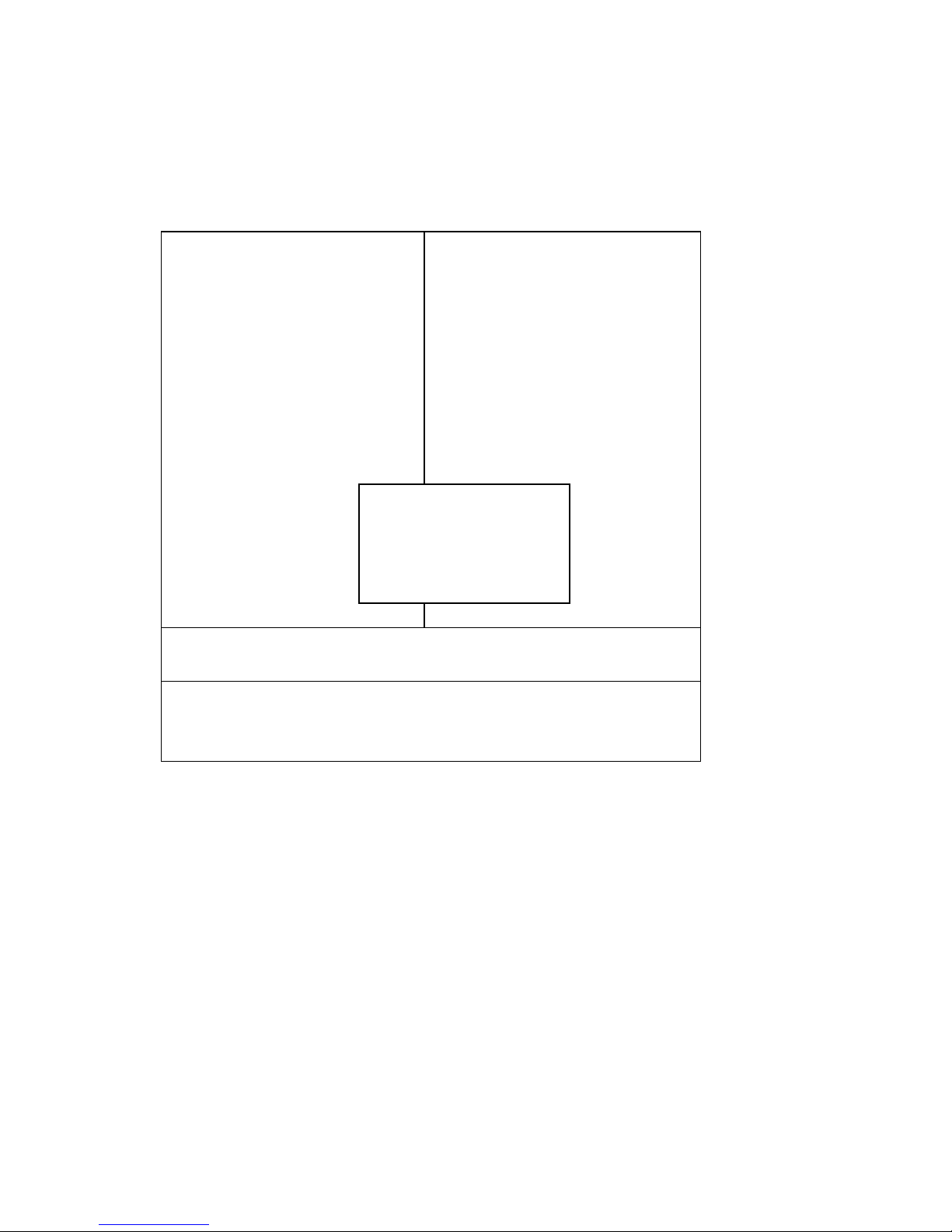
After you have completed adjusting all the settings as required, you must remember to save
these setting into the CMOS RAM. To save the settings, select “SAVE & EXIT SETUP” and
press <Enter>, a display will be shown as follows:
Phoenix - AwardBIOS CMOS Setup Utility
►Standard CMOS Features
►Advanced BIOS Features
►Advanced Chipset Features
►Integrated Peripherals
►Power Management
►PnP/PCI Configura
►PC Health Status
►Frequency Control
Load Fail-Safe Defaults
Load Optimized Defaults
Set Supervisor Password
word
etup
Saving
Esc : Quit ↑↓→← : Select Item
F10 : Save & Exit Setup
Save Data to CMOS
When you confirm that you wish to save the settings, your system will be automatically restarted and
the changes you have made will be implemented. You may always call up the setup program at any
time to adjust any of the individual items by pressing the <Del> key during boot up.
5.15 EXIT WITHOUT SAVING
If you wish to cancel any changes you have made, you may select the “EXIT WITHOUT
SAVING” and the original setting stored in the CMOS will be retained. The screen will be shown
as below:
Save to CMOS and EXIT
Y/N)? Y
Page 76
EX-96085 User Manual
76
Phoenix - AwardBIOS CMOS Setup Utility
►Standard CMOS Features
►Advanced BIOS Features
►Advanced Chipset Features
►Integrated Peripherals
►Power Management
►PnP/PCI Configura
►PC Health Status
►Frequency Control
Load Fail-Safe Defaults
Load Optimized Defaults
Set Supervisor Password
word
etup
Saving
Esc : Quit ↑↓→← : Select Item
F10 : Save & Exit Setup
Abandon all Datas
Quit Without Saving
(Y/N)? N
Page 77
EX-96085 User Manual
77
Chapter 6 Touch Driver Installation
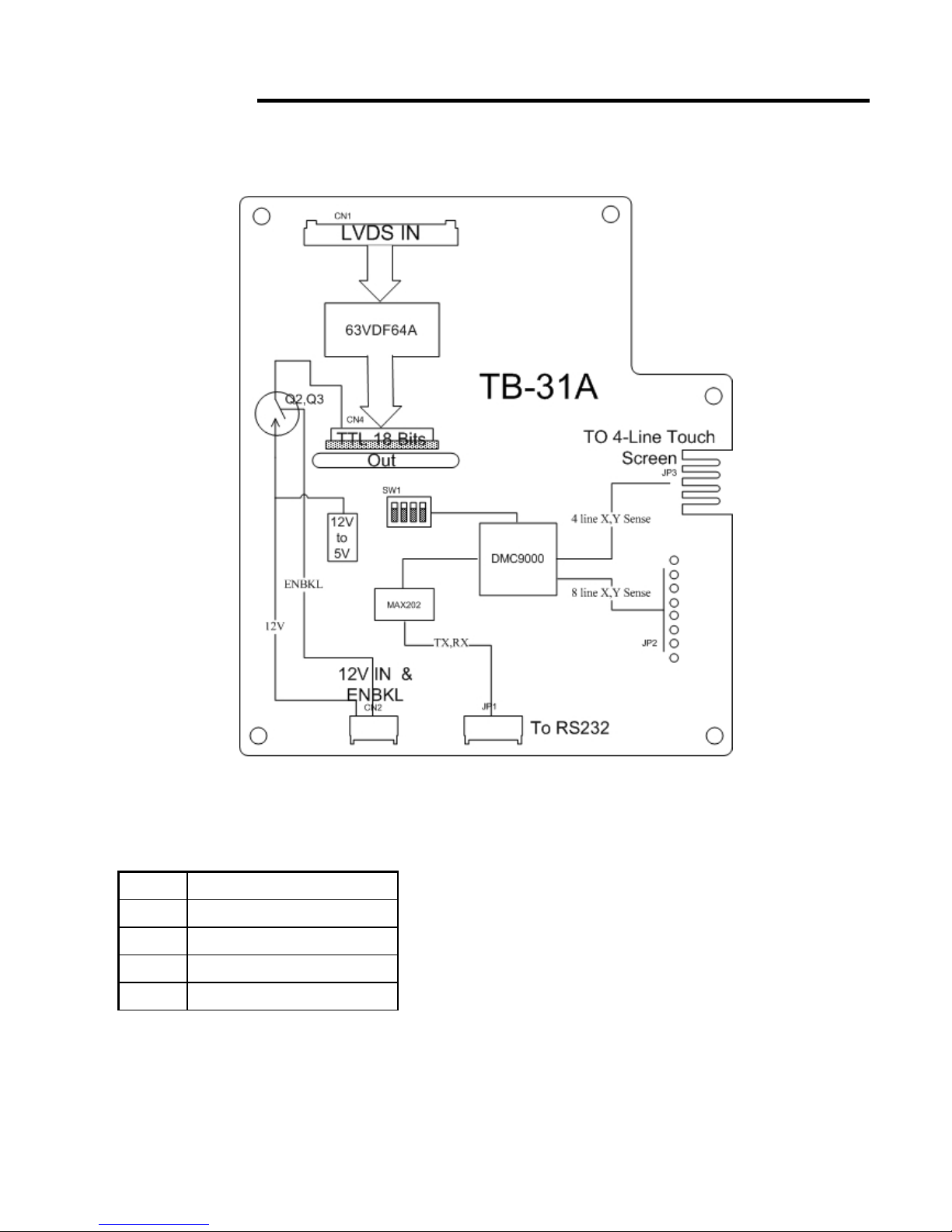
6.1 Introduction to the TB-31 Touch Screen Controll Board
CN5 (PH2.54mm FFC SMD Socket)
PIN ASSIGNMENT
1 Right
2 Left
3 Bottom
4 Top
Page 78
EX-96085 User Manual
78
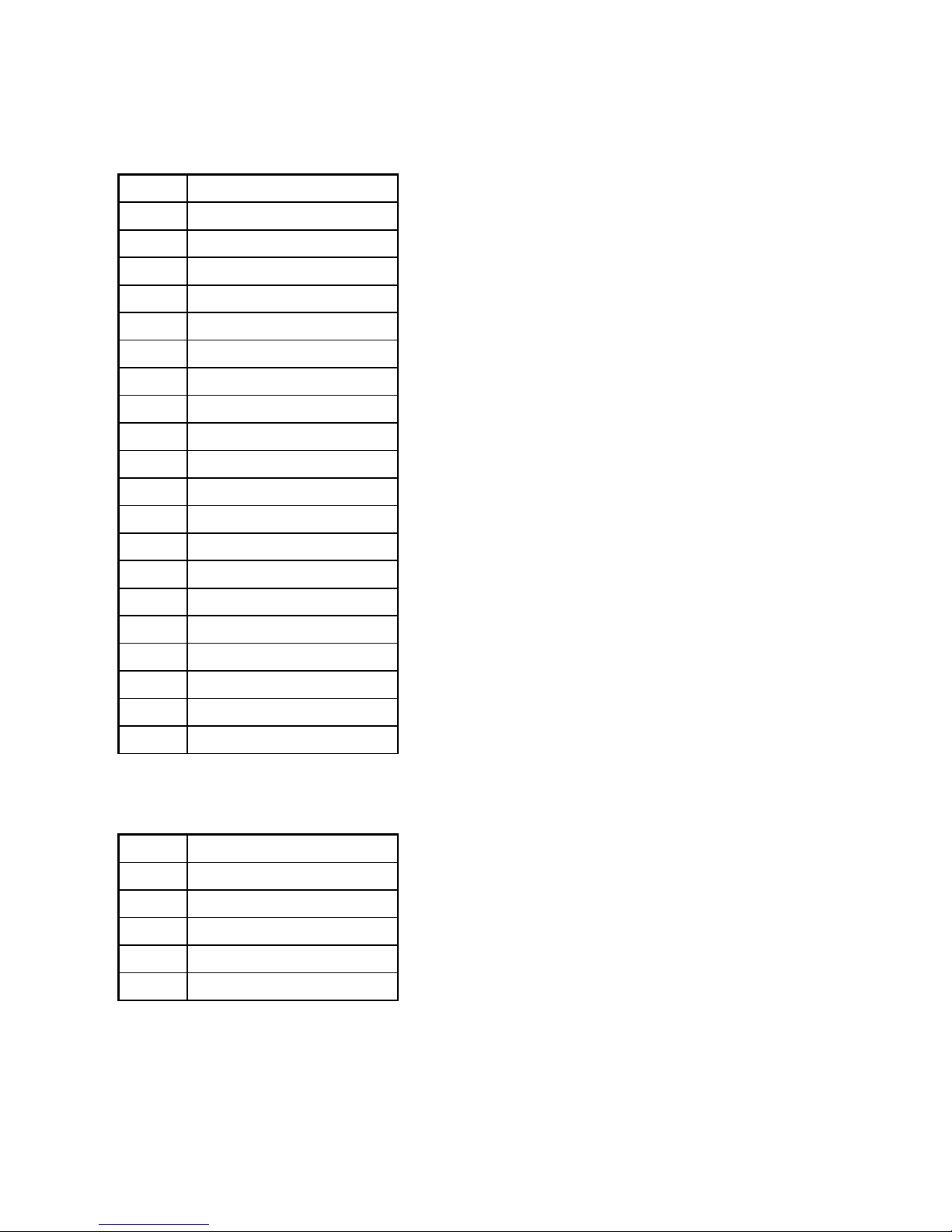
CN1 (Hirose DF 14-20S)
PIN ASSIGNMENT
1 GND
2 GND
3 3.3V
4 3.3V
5 GND
6 GND
7 RX0_
8 RX0+
9 GND
10 RX1_
11 RX1+
12 GND
13 RX2_
14 RX2+
15 GND
16 RXC_
17 RXC+
18 GND
19 GND
20 GND
CN2 (Hirose DF 14-5S)
PIN ASSIGNMENT
1 12V
2 12V
3 ENBKL
4 GND
5 GND
Page 79
EX-96085 User Manual
79
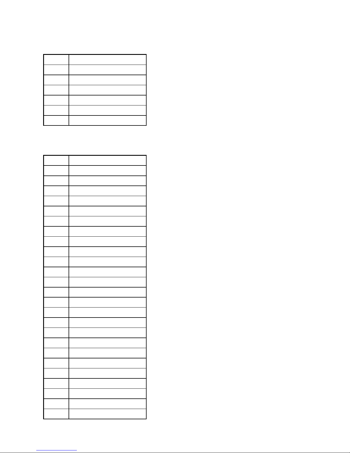
CN4 (Hirose DF 14-6S)
PIN ASSIGNMENT
1 TXD
2 RXD
3 RTS
4 GND
5 DSR
6 DTR
CN3 (JAE IL-FPR-40S (Lower))
PIN ASSIGNMENT
1 12-FPVEE
2 12-FPVEE
3 12-FPVEE
4 12-FPVEE
5 12-FPVEE
6 GND
7 GND
8 GND
9 GND
10 GND
11 N.C
12 N.C.
13 DE
14 GND
15 B5
16 B4
17 B3
18 B2
19 B1
20 B0
21 GND
22 G5
23 G4
24 G3
25 G2
Page 80

EX-96085 User Manual
80
26 G1
27 G0
28 GND
29 R5
30 R4
31 R3
32 R2
33 R1
34 R0
35 GND
36 GND
37 GND
38 GND
39 CLK
40 GND
Page 81
EX-96085 User Manual
81
6.2 Configuring the PenMount Windows 2000/XP Driver
Upon rebooting, the computer automatically finds new touch screen controller. The touch
screen is connected but not calibrated. Follow the procedures below to carry out
calibration.
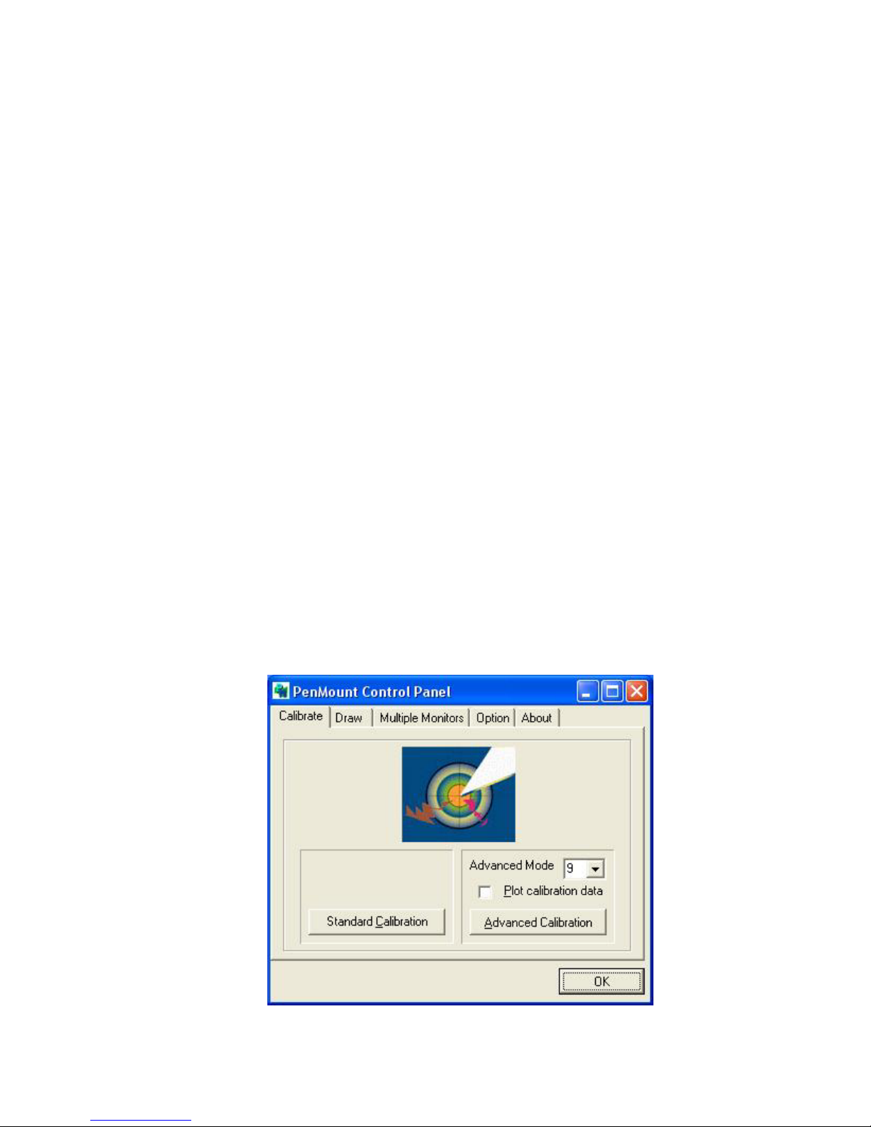
1. After installation, click the PenMount Monitor icon “PM” in the menu bar.
2. When the PenMount Control Panel appears, click “Calibrate”.
PenMount Control Panel
The functions of the PenMount Control Panel are Calibrate, Draw, Multiple Monitors,
Option, and About, which are explained in the following sections.
Calibrate
This function offers two ways to calibrate your touch screen. “Standard Calibration”
adjusts most touch screens. “Advanced Calibration” adjusts aging touch screens.
Standard Calibration
Click this button and arrows appear pointing to
red squares. Use your finger or stylus to touch
the red squares in sequence. After the fifth red
point calibration is complete. To skip, press
‘ESC’.
Advanced Calibration Advanced Calibration uses 4, 9, 16 or 25 points
to effectively calibrate touch panel linearity of
aged touch screens. Click this button and
touch the red squares in sequence with a
stylus. To skip, press ‘ESC’.
Page 82
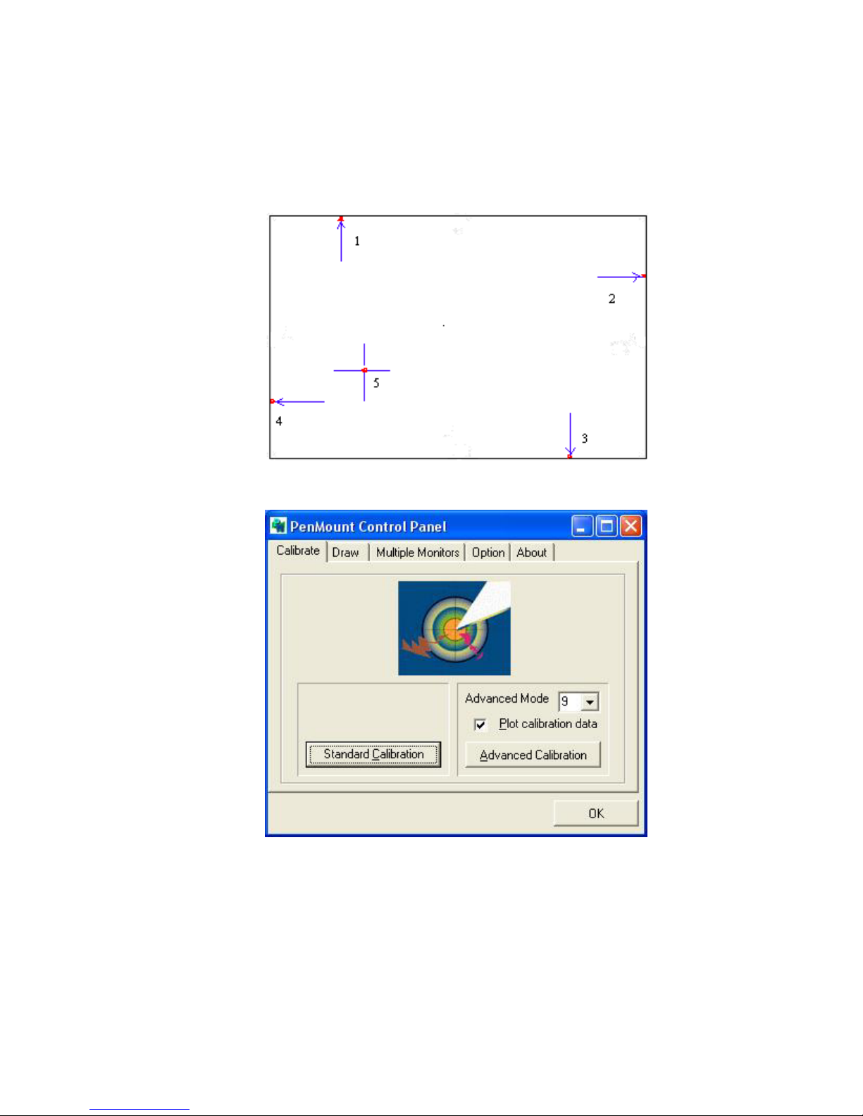
EX-96085 User Manual
82
NOTE: The older the touch screen is, the more Advanced Mode calibration points you need
for an accurate calibration. Use a stylus during Advanced Calibration for greater
accuracy.
Page 83
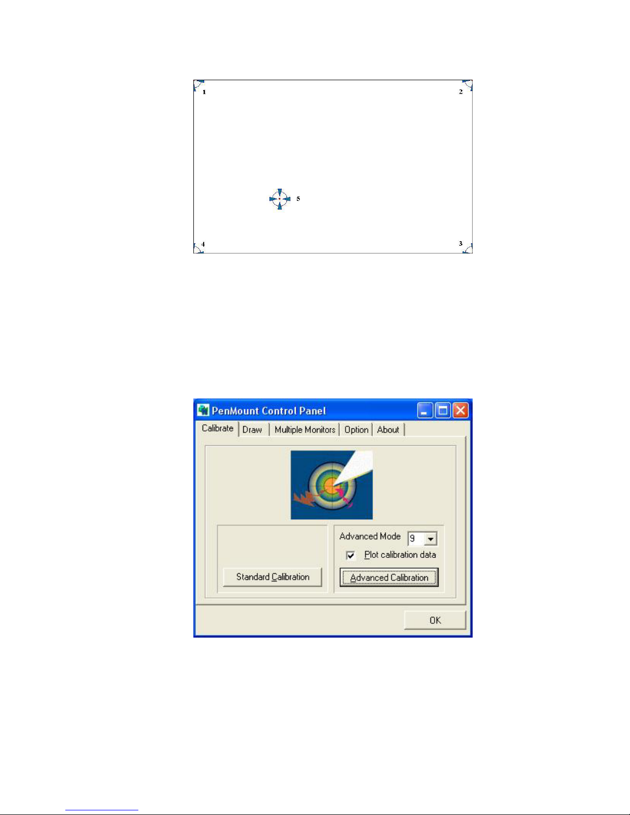
EX-96085 User Manual
83
Plot Calibration Data Check this function and a touch panel linearity
comparison graph appears when you have
finished Advanced Calibration. The blue lines
show linearity before calibration and black
lines show linearity after calibration.
Page 84
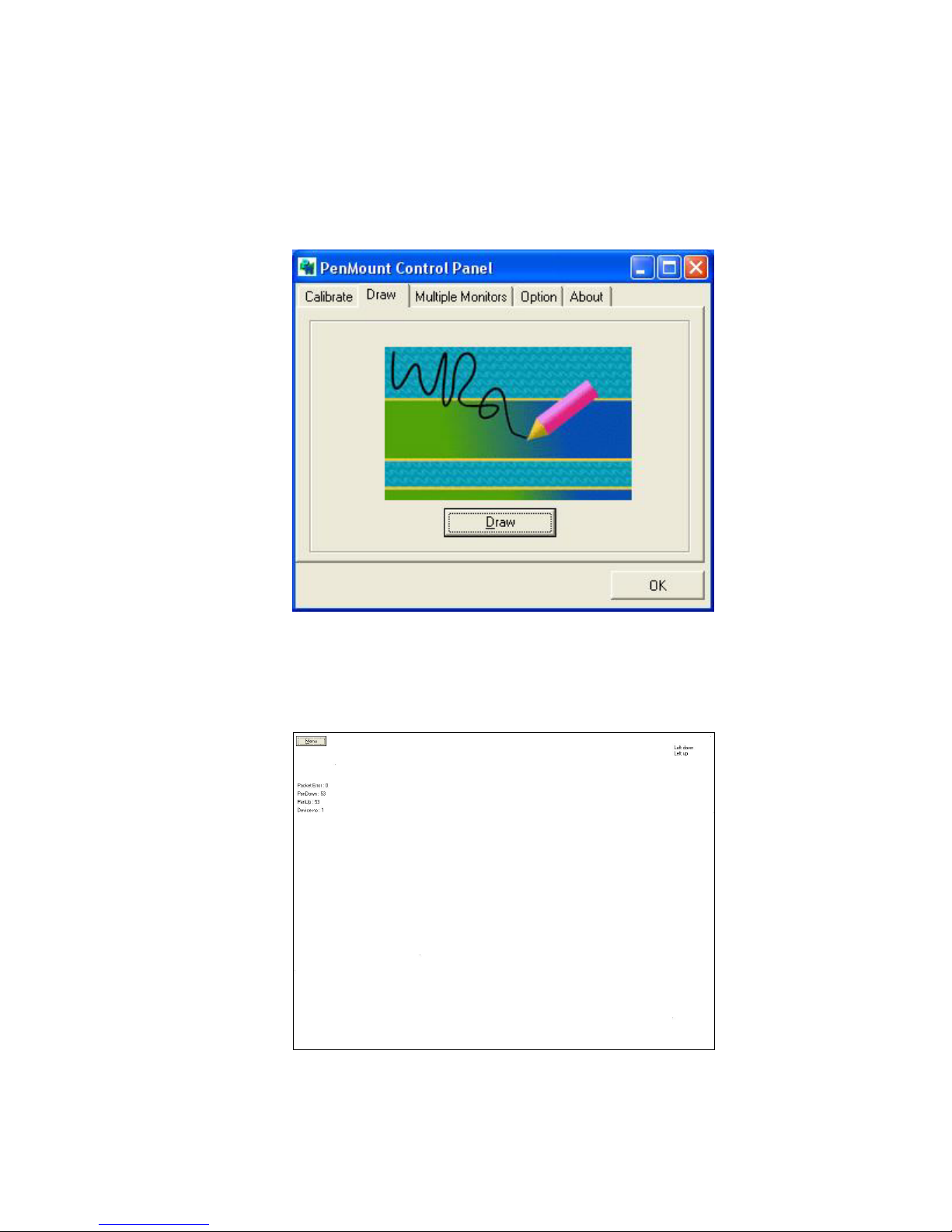
EX-96085 User Manual
84
Draw
Tests or demonstrates the PenMount touch screen operation. The display shows touch
location. Click Draw to start. Touch the screen with your finger or a stylus and the
drawing screen will register touch activity such as left, right, up, down, pen up, and
pen down.
Touch the screen with your finger or a stylus and the drawing screen will register touch
activity such as left, right, up, down, pen up, and pen down.
Page 85
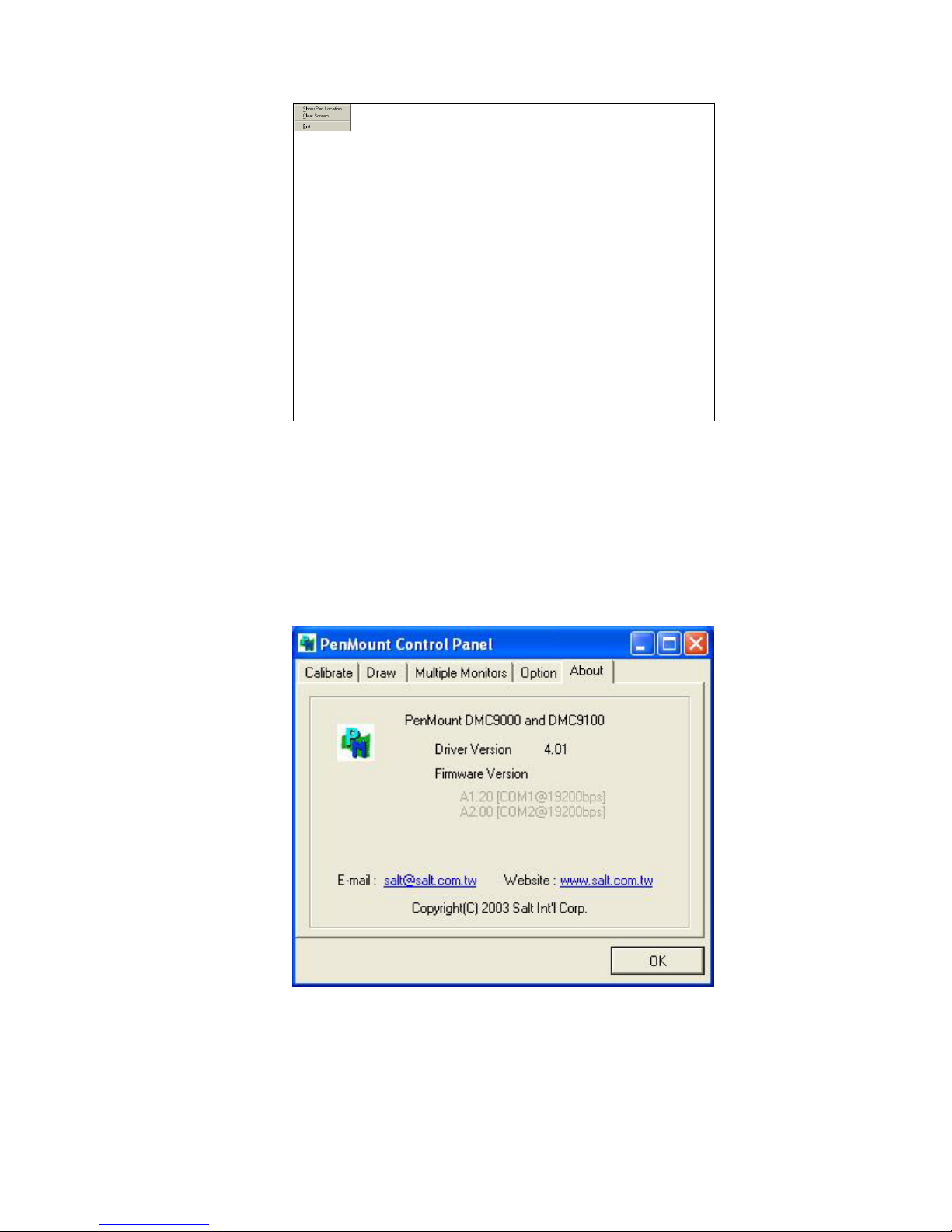
EX-96085 User Manual
85
Click Clear Screen to clear the drawing.
About
This panel displays information about the PenMount controller and this driver version.
PenMount Monitor Menu Icon
The PenMount monitor icon (PM) appears in the menu bar of Windows 2000/XP system
Page 86
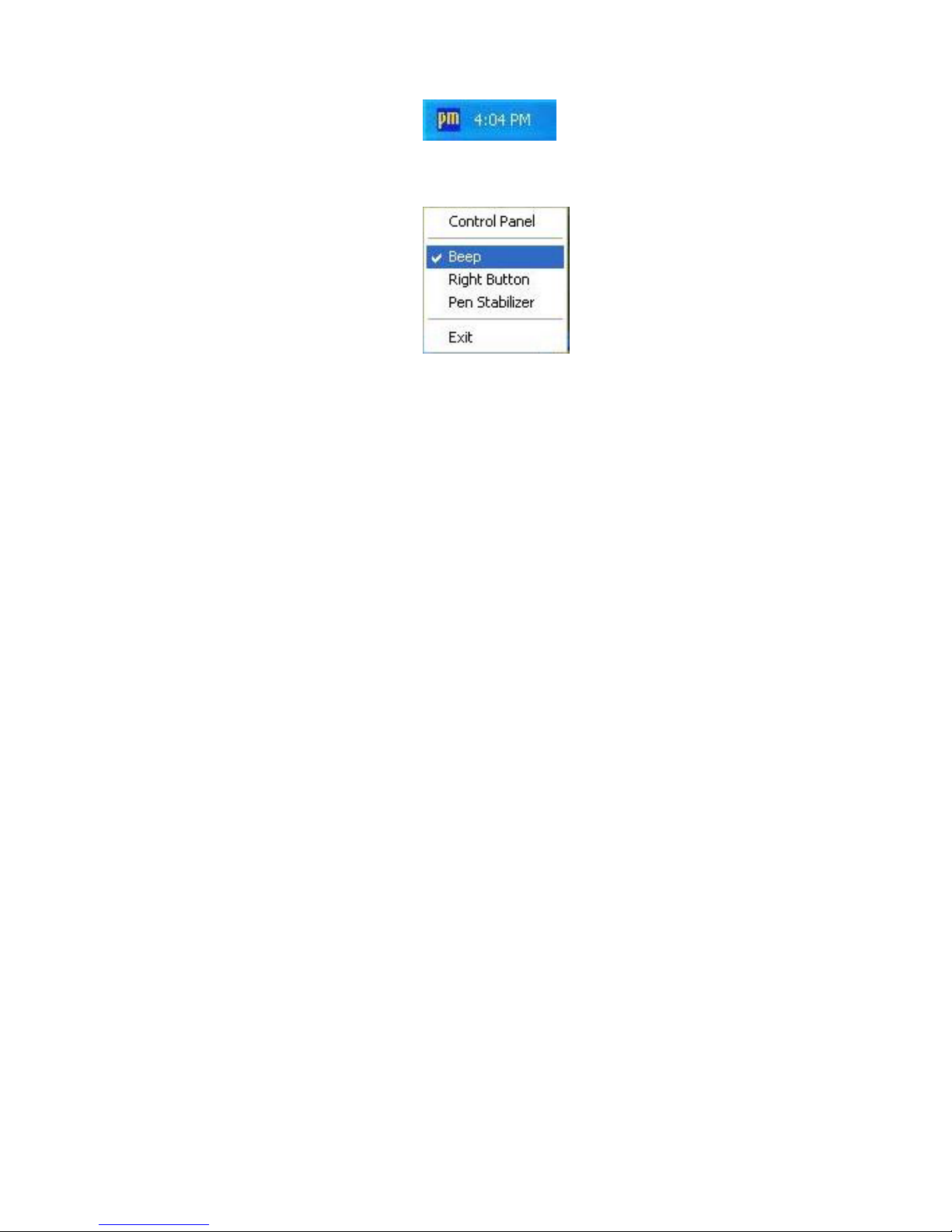
EX-96085 User Manual
86
when you turn on the PenMount Monitor in the PenMount Utilities.
The PenMount Monitor has the following functions:
Page 87

EX-96085 User Manual
87
Beep Turns beep on or off.
Right Button When you select this function, a mouse icon
appears in the right-bottom of the screen. Click
this icon to switch between Right and Left
Button functions.
Pen Stabilizer Check this function to reduce cursor vibration
for relatively unstable touch screens, or where
there may be excess vibration. Normally this
function is not checked.
Exit Exits the PenMount Monitor function.
Page 88
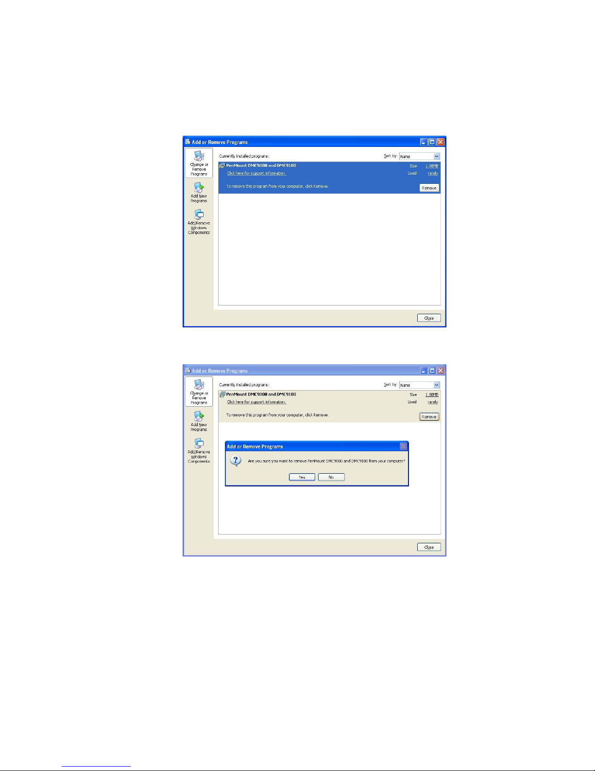
EX-96085 User Manual
88
6.3 Uninstall the PenMount Windows 2000/XP Driver
1. Exit the PenMount monitor (PM) in the menu bar.
2. Go to Settings, then Control Panel, and then click Add/Remove program. Select
PenMount DMC9000 and click the Add/Remove button.
3. Select PenMount DMC9000 and DMC9100. Click the Remove button.
4. Select “Yes” and “Close” to remove the PenMount Windows 2000/XP driver, and
reboot the system.
Page 89

EX-96085 User Manual
89
6.4 Software Functions
Stream/Point Mode
Stream and point modes control the touch and drag function of the touch screen. The
point mode only allows “touch” interaction with the screen and does not allow the user to
drag objects. The point mode is useful for maintaining the location of screen icons such
on POS terminals. The stream mode allows a user to touch and drag icons and other
items around on the screen, similar to using a mouse.
Drawing Mode
Drawing mode is a utility that lets the user draw on the screen using a finger or stylus.
This allows the user to test the touch screen and touch controller to see if it is operational
or is mapped correctly. The drawing mode can display either the matrix address of points
touched or just show lines drawn. One of the PenMount driver’s strengths is a special
mathematical algorithm that minimizes the occurrence of noise and smooths the drawing
of lines.
Beep Sound
All of PenMount’s drivers support the beep sound function; however, some PC systems
may only offer a fixed buzzer sound.
Beep Sound Adjustable
Software drivers for Windows systems let the user adjust the frequency and length of the
beep sound. The drivers let the user adjust the desired touch screen sound, as well as
turn the sound off.
Wake Up Function
The Wake Up function lets the user touch the screen and wake the system up from
‘suspend’ mode.
Point Calibration Data
The Plot Calibration Data function displays the touch screen linearity map, which is
available if the PenMount driver provides an Advance Calibration function when touch
screens age their touch linearity declines. This non-linearity is apparent when the
touched point on the touch screen is not the same as the point on the display. The plot
calibration data function shows the linearity status of the touch screen. This is only a
support function for the user. The exact linearity of a touch screen requires a linearity
Page 90

EX-96085 User Manual
90
test machine.
Right Button
The Right Button function simulates the right button function of a mouse. Click the right
button and the user can only touch the screen once and the driver changes the touch
definition to the left button.
Hide Cursor
The Hide Cursor function keeps the cursor arrow and other cursor symbols from
appearing when using the touch screen. The cursor appears when the user turns this
function off.
Cursor Offset
The Cursor Offset function lets the user adjust the position of the touch point to a desired
location away from the real touch point.
Double-Click Area and Speed
The Double-Click Area and Speed function lets the user adjust the double-click area and
speed to their personal preference.
About
This option shows the exact version of the drivers and controller firmware. Updated
drivers are available for download on the PenMount website.
Page 91

EX-96085 User Manual
91
Appendix: Mainboard Technical Summary
This section introduce you the maps concisely.
Sections include:
z Block Diagram
z Interrupt Map
z RTC (Standard) RAM Bank
z Timer & DMA Channels Map
z I / O & Memory Map
Page 92
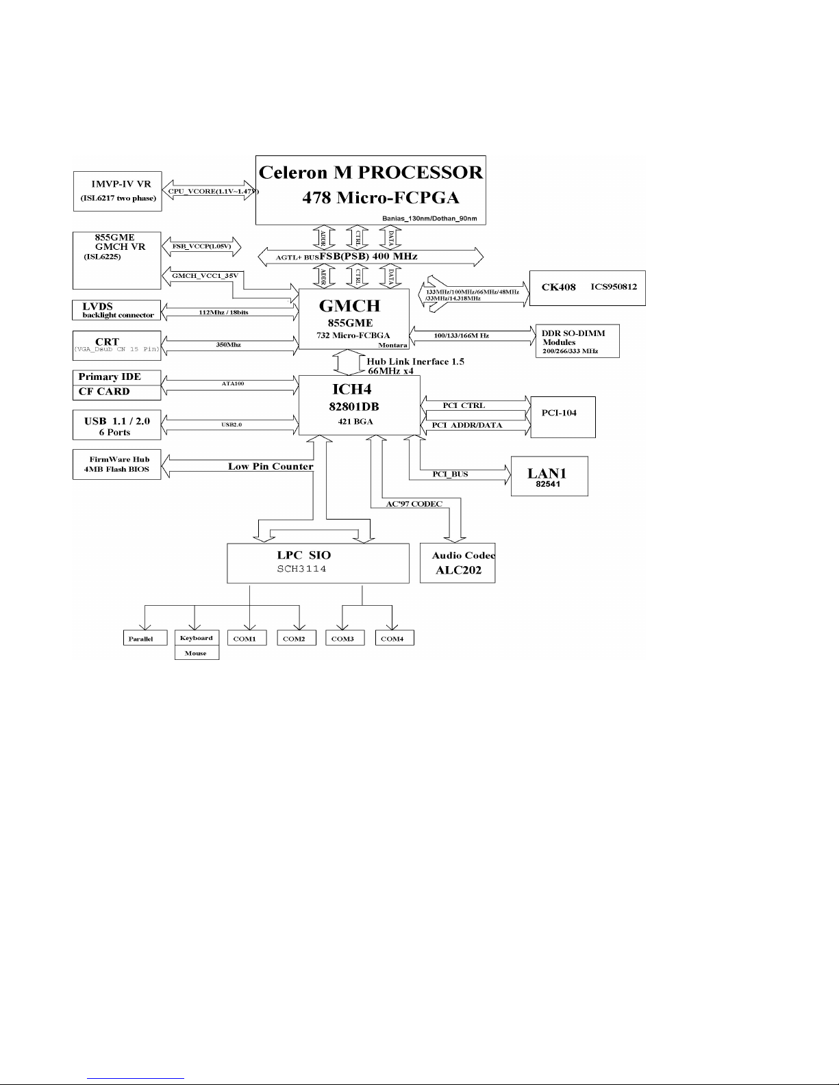
EX-96085 User Manual
92
BLOCK DIAGRAM
Page 93

EX-96085 User Manual
93
INTERRUPT MAP
IRQ ASSIGNMENT
0 System TIMER interrupt from
TIMER-0
1 Keyboard output buffer full
2 Cascade for IRQ 8-15
3 Serial port 2
4 Serial port 1
5 Available
6 Floppy Disk adapter
7 Parallel port 1
8 RTC clock
9 ACPI-Compliant System
10 Serial port 3
11 Serial port 4
12 PS/2 Mouse
13 Math coprocessor
14 Hard Disk adapter
15 Hard Disk adapter
Page 94

EX-96085 User Manual
94
RTC (STANDARD) RAM BANK
CODE ASSIGNMENT
00h Seconds
01h Second alarm
02h Minutes
03h Minutes alarm
04h Hours
05h Hours alarm
06h Day of week
07h Day of month
08h Month
09h Year
0Ah Status register A
0Bh Status register B
0Ch Status register C
0Dh Status register D
0Eh-7Fh 114 Bytes of User RAM
Page 95

EX-96085 User Manual
95
TIMER & DMA CHANNELS MAP
Timer Channel Map :
Timer
Channel
Assignment
0 System timer interrupt
1 DRAM Refresh request
2 Speaker tone generator
DMA Channel Map :
DMA
Channel
Assignment
0 Available
1 Available
2 Floppy Disk adapter
3 Available
4 Cascade
5 Available
6 Available
7 Available
Page 96

EX-96085 User Manual
96
I/O & MEMORY MAP
Fixed I/O Ranges Decoded by ICH2 :
I/O Address Read Target Write Target Internal Unit
00h-08h
DMA Controller DMA Controller DMA
09h-0Eh Reserved DMA Controller DMA
0Fh DMA Controller DMA Controller DMA
10h-18h DMA Controller DMA Controller DMA
19h-1Eh Reserved DMA Controller DMA
1Fh DMA Controller DMA Controller DMA
20h-21h Interrupt Controller Interrupt Controller Interrupt
24h-25h Interrupt Controller Interrupt Controller Interrupt
28h-29h Interrupt Controller Interrupt Controller Interrupt
2Ch-2Dh Interrupt Controller Interrupt Controller Interrupt
2Eh-2Fh LPC SIO LPC SIO Forwarder to LPC
30h-31h Interrupt Controller Interrupt Controller Interrupt
34h-35h Interrupt Controller Interrupt Controller Interrupt
38h-39h Interrupt Controller Interrupt Controller Interrupt
3Ch-3Dh Interrupt Controller Interrupt Controller Interrupt
40h-42h Timer/Counter Timer/Counter PIT (8254)
43h Reserved Timer/Counter PIT
4E-4F LPC SIO LPC SIO Forwarder to LPC
50h-52h Timer/Counter Timer/Counter PIT
53h Reserved Timer/Counter PIT
60h Microcontroller Microcontroller Forwarder to LPC
61h NMI Controller NMI Controller Processor I/F
62h Microcontroller Microcontroller Forwarder to LPC
63h NMI Controller NMI Controller Processor I/F
64h Microcontroller Microcontroller Forwarder to LPC
65h NMI Controller NMI Controller Processor I/F
66h Microcontroller Microcontroller Forwarder to LPC
67h NMI Controller NMI Controller Processor I/F
70h Reserved5 NMI & RTC controller RTC
71h RTC Controller RTC Controller RTC
72h RTC Controller NMI & RTC controller RTC
73h RTC Controller RTC Controller RTC
74h RTC Controller NMI & RTC controller RTC
75h RTC Controller RTC Controller RTC
76h RTC Controller NMI & RTC controller RTC
77h RTC Controller RTC Controller RTC
Page 97

EX-96085 User Manual
97
I/O Address Read Target Write Target Internal Unit
80h DMA Controller DMA controller &
LPC/PCI
DMA
81h-83h DMA Controller DMA Controller DMA
84h-86h DMA Controller DMA Controller &
LPC or PCI
DMA
87h DMA Controller DMA Controller DMA
88h DMA Controller DMA Controller &
LPC or PCI
DMA
89h-8Bh DMA Controller DMA Controller DMA
8Ch-8Eh DMA Controller DMA Controller &
LPC or PCI
DMA
08Fh DMA Controller DMA Controller DMA
90h-91h DMA Controller DMA Controller DMA
92h Reset Generator Reset Generator Processor I/F
93h-9Fh DMA Controller DMA Controller DMA
A0h-A1h Interrupt Controller Interrupt Controller Interrupt
A4h-A5h Interrupt Controller Interrupt Controller Interrupt
A8h-A9h Interrupt Controller Interrupt Controller Interrupt
ACh-ADh Interrupt Controller Interrupt Controller Interrupt
B0h-B1h Interrupt Controller Interrupt Controller Interrupt
B2h-B3h Power Management Power Management Power Management
B4h-B5h Interrupt Controller Interrupt Controller Interrupt
B8h-B9h Interrupt Controller Interrupt Controller Interrupt
BCh-BDh Interrupt Controller Interrupt Controller Interrupt
C0h-D1h DMA Controller DMA Controller DMA
D2h-DDh Reserved DMA Controller DMA
DEh-DFh DMA Controller DMA Controller DMA
F0h See Note 3 FERR# /IGNNE#/
Interrupt Controller
Processor interface
170h-177h IDE Controller1 IDE Controller1 Forwarded to IDE
1F0h-1F7h IDE Controller2 IDE Controller2 Forwarded to IDE
376h IDE Controller1 IDE Controller1 Forwarded to IDE
3F6h IDE Controller2 IDE Controller2 Forwarded to IDE
4D0h-4D1h Interrupt Controller Interrupt Controller Interrupt
CF9h Reset Generator Reset Generator Processor interface
Notes:
1. Only if IDE Standard I/O space is enabled for Primary Drive. Otherwise, the target is PCI.
2. Only if IDE Standard I/O space is enabled for Secondary Drive. Otherwise, the target is PCI.
Page 98

EX-96085 User Manual
98
3. If POS_DEC_EN bit is enabled, reads from F0h will not be decoded by the ICH2. If
POS_DEC_EN is not enabled, reads from F0h will forward to LPC.
Memory Decode Ranges From Processor Perspective :
Memory Range Target Dependency/Comments
0000 0000h-000D FFFFh
0010 0000-TOM (Top of Memory)
Main
Memory
TOM registers in Host Controller
000E 0000h-000F FFFFh FWH Bit 7 in FWH Decode Enable Register is set
FEC0 0000h-FEC0 0100h I/O APIC
inside ICH2
FFC0 0000h-FFC7 FFFFh
FF80 0000h-FF87 FFFFh
FWH Bit 0 in FWH Decode Enable Register
FFC8 0000h-FFCF FFFFh
FF88 0000h-FF8F FFFFh
FWH Bit 1 in FWH Decode Enable Register
FFD0 0000h-FFD7 FFFFh
FF90 0000h-FF97 FFFFh
FWH Bit 2 in FWH Decode Enable Register is set
FFD8 0000h-FFDF FFFFh
FF98 0000h-FF9F FFFFh
FWH Bit 3 in FWH Decode Enable Register is set
FFE0 0000h-FFE7 FFFFh
FFA0 0000h-FFA7 FFFFh
FWH Bit 4 in FWH Decode Enable Register is set
FFE8 0000h-FFEF FFFFh
FFA8 0000h-FFAF FFFFh
FWH Bit 5 in FWH Decode Enable Register is set
FFF0 0000h-FFF7 FFFFh
FFB0 0000h-FFB7 FFFFh
FWH Bit 6 in FWH Decode Enable Register is set
FFF8 0000h-FFFF FFFFh
FFB8 0000h-FFBF FFFFh
FWH Always Enabled.
The top two 64K blocks of this range can be
swapped as described in Section 6.4.1.
FF70 0000h-FF7F FFFFh
FF30 0000h-FF3F FFFFh
FWH Bit 3 in FWH Decode Enable 2 Register is
set
FF60 0000h-FF6F FFFFh
FF20 0000h-FF2F FFFFh
FWH Bit 2 in FWH Decode Enable 2 Register is
set
FF50 0000h-FF5F FFFFh
FF10 0000h-FF1F FFFFh
FWH Bit 1 in FWH Decode Enable 2 Register is
set
FF40 0000h-FF4F FFFFh
FF00 0000h-FF0F FFFFh
FWH Bit 0 in FWH Decode Enable 2 Register is
set
Anywhere in 4GB range D110 LAN
Controller
Enable via BAR in Device 29:Function 0
(D110 LAN Controller)
All Other PCI None
 Loading...