

TOPSCCC EX-9392B-ATOM User Manual

EX-9392B-ATOM Embedded System
Page i
MODEL:
EX-9392B-
A
TOM
TOPSCCC Intel® Atom Fanless Embedded System
RoHS Compliant, Dual GbE LAN, COM Ports, USB 2.0
Rev. 1.02 10 July, 2009
User Manual

EX-9392B-ATOM Embedded System
Page ii
Revision
Date Version Changes
10 July, 2009 1.02 Modified COM2 information
17 March, 2009 1.01 Changed model name
10 February, 2009 1.00 Initial release

EX-9392B-ATOM Embedded System
Page iii
Copyright
COPYRIGHT NOTICE
The information in this document is subject to change without prior notice in order to
improve reliability, design and function and does not represent a commitment on the part
of the manufacturer.
In no event will the manufacturer be liable for direct, indirect, special, incidental, or
consequential damages arising out of the use or inability to use the product or
documentation, even if advised of the possibility of such damages.
This document contains proprietary information protected by copyright. All rights are
reserved. No part of this manual may be reproduced by any mechanical, electronic, or
other means in any form without prior written permission of the manufacturer.
TRADEMARKS
All registered trademarks and product names mentioned herein are used for identification
purposes only and may be trademarks and/or registered trademarks of their respective
owners.

EX-9392B-ATOM Embedded System
Page iv
Packing List
NOTE:
If any of the components listed in the checklist below are missing, please do not
proceed with the installation. Contact the TOPSCCC reseller or vendor you
purchased the EX-9392B from or contact an TOPSCCC sales representative
directly. To contact an TOPSCCC sales representative, please send an email
to sales@topsccc.com
The items listed below should all be included in the EX-9392B package.
1 x EX-9392B embedded system
2 x Mounting brackets
1 x Screw set
1 x Thermal pad for HDD
1 x Mini jumper set
1 x QIG
1 x Driver and manual CD
1 x 2 dbi wireless antenna (for wireless models only)
1 x Power cord (optional for WD models)
1 x Power Adaptor (optional for WD models)

EX-9392B-ATOM Embedded System
Page v
Table of Contents
1 INTRODUCTION.....................................................................................................1
1.1 EX-9392B E
MBEDDED SYSTEM OVERVIEW ..............................................................2
1.1.1 EX-9392B Benefits............................................... ..................................... ......... 2
1.1.2 EX-9392B Features........................................ ...................................... .............. 2
1.2 EX-9392B M
ODEL VARIATIONS.................................................................................3
1.3 T
ECHNICAL SPECIFICATIONS ...................................................................................... 4
1.4 P
OWER MODULE SPECIFICATIONS.............................................................................. 6
1.4.1 Power Module Options................................ .. ...................................... .............. 6
1.4.2 Power Module Specifications ............................................................................ 6
1.5 P
OWER ADAPTER....................................................................................................... 7
2 MECHANICAL DESCRIPTION............................................................................ 9
2.1 EX-9392B MECHANICAL OVERVIEW ...................................................................... 10
2.2 P
HYSICAL DIMENSIONS............................................................................................ 10
2.2.1 EX-9392B Dimensions.............................................. ..................................... ..10
2.2.2 Motherboard Dimens ions.................................................................................11
2.2.3 Power Module Dimensions..............................................................................12
2.3 E
XTERNAL OVERVIEW ............................................................................................. 13
2.3.1 Front Panel ...................................................................................................... 13
2.3.2 Rear Panel ............................................................. .......................................... 13
2.3.3 Bottom Surface.................................................. ............................................... 14
2.4 I
NTERNAL OVERVIEW............................................................................................... 15
3 SYSTEM COMPONENTS .................................................................................... 17
3.1 EX-9392B EMBEDDED SYSTEM MOTHERBOARD .................................................... 18
3.1.1 EX-9392B Embedded System Motherboard..................................................... 18
3.1.2 EXPERT Motherboard Overview.....................................................................18
3.1.3 CPU Support..................................... ... ..... ... ..... ..... ... ..... ... ..... ...... .. ...... .. ...... ....19
3.2 P
ERIPHERAL INTERFACE CONNECTORS ....................................................................19
3.2.1 Peripheral Interface Connectors.....................................................................19
3.3 I
NTERNAL PERIPHERAL CONNECTORS......................................................................20

EX-9392B-ATOM Embedded System
Page vi
3.3.1 ATX Power Connector...................................... ........... ........ .......... ........... .......20
3.3.2 ATX Power Supply Enable Connector............................................................. 21
3.3.3 Audio Connector (10- pin)...................... ... ................................... .................... 22
3.3.4 CompactFlash® Socket................ .. ...... .. ...... .. ...... ..... ... ..... ... ..... ..... ... ..... ... ..... ..23
3.3.5 LED Connector................................................................................................25
3.3.6 PCIe Mini Card Slot ................................................. ..................................... ..26
3.3.7 Power Button Connector...................................................... ............................28
3.3.8 Reset Button Connector......................................... .......................................... 28
3.3.9 SATA Drive Connectors................................................................................... 29
3.3.10 Serial Port Connector (COM3, COM4, COM5 and COM6)......................... 30
3.3.11 Serial Port Connector (COM 2)..................................................................... 32
3.3.12 USB Connectors (Internal)............................................................................ 33
3.4 E
XTERNAL PERIPHERAL INTERFACE CONNECTOR PANEL .........................................34
3.4.1 LAN Connectors............................................................................................... 34
3.4.2 Serial Port Connector (COM1)............................................. ..........................35
3.4.3 USB Connectors................................................... .. ...... ..... ... ..... ... ..... ..... ... ..... ..36
3.4.4 VGA Connector...................................................... ........ ........... ........... ........ ....37
3.5 EXPERT
MOTHERBOARD ON-BOARD JUMPERS ......................................................38
3.5.1 CF Card Setup ..................................................... .. ...... ..... ... ..... ... ..... ..... ... ..... ..39
3.5.2 Clear CMOS Jumper...................... ... ..................................... .......................... 39
3.5.3 COM 2 Function Select Jumper..................................... ..................................41
3.6 CONNECTOR MAPPINGS...........................................................................................42
3.6.1 Power Connector.............................. ... ..................................... ....................... 42
3.6.2 ATX Mode Connector............................. ........... ........ ........... ........ .......... ..........42
4 INSTALLATION .................................................................................................... 43
4.1 A
NTI-STATIC PRECAUTIONS...................................................................................... 44
4.2 I
NSTALLATION PROCEDURE......................................................................................44
4.2.1 Installation Procedure Overview..................................................................... 44
4.2.2 Unpacking............................................................ .. ...... .. ...... ..... ... ..... ..... ... ..... ..45
4.2.3 Bottom Surface Removal...................................................... .. .......................... 47
4.2.4 Configure the Jumper Settings.........................................................................47
4.2.5 Hard Drive Installati on............................. ..... ...... .. ...... ..... ... ..... ..... ... ..... ... ..... ..48
4.2.6 Mounting the System with Mounting Brackets....... .......................................... 50
4.2.7 Mounting the System with Wall Mount Kit....................................................... 51

EX-9392B-ATOM Embedded System
Page vii
4.2.8 DIN Mounting...................... .. ...... ..... ... ..... ... ..... ..... ... ..... ...... .. ...... .. ...... ..... ... ....53
4.2.9 Wireless Antenna Installation (Wireless Models Only).................................... 55
4.2.10 Cable Connections..................................... .. ................................... ... ............ 56
4.3 P
OWER-ON PROCEDURE .......................................................................................... 56
4.3.1 Installation Checklist........................ ... ..................................... ....................... 56
4.3.2 Terminal Block Pinouts................................ ........ .......... ........ ........... ........... ....57
4.3.3 Power-on Procedure .................................................... ....................................57
5 BIOS SCREENS............................ ... ..................................... ..................................59
5.1 I
NTRODUCTION ........................................................................................................ 60
5.1.1 Starting Se tup....................................................... .. ...... .. ...... ..... ... ..... ... ..... ..... ..60
5.1.2 Using Setup....................... ..... ... ..... ...... .. ...... .. ...... ..... ... ..... ..... ... ..... ... ..... ...... .. ..60
5.1.3 Getting Help......................................................... ..... ... ..... ... ..... ..... ... ..... ...... .. ..61
5.1.4 Unable to Reboot After Configuration Changes..............................................61
5.1.5 BIOS Menu Bar......................................................... ... ....................................61
5.2 M
AIN ....................................................................................................................... 62
5.3 A
DVANCED............................................................................................................... 63
5.3.1 CPU Configuration.............................................................. ..... ..... ... ..... ... ..... ..64
5.3.2 IDE Configuration....................... .................................. ... ...............................65
5.3.2.1 IDE Master, IDE Slave ............................................................................. 67
5.3.3 Super IO Configuration ................................................................................... 73
5.3.4 Hardw are Health Configuration....................................................... ... ..... ..... ..77
5.3.5 Power Configuration............ .. ...... ..... ... ..... ..... ... ..... ...... .. ...... ..... ... ..... ... ..... ..... ..81
5.3.5.1 ACPI configuration....................................... ............................. ............... 81
5.3.5.2 APM Configuration.................................... ................................ ............... 82
5.3.6 Remote Configuration....................................... ... ..... ..... ... ..... ...... .. ...... .. ...... ....85
5.3.7 USB Configuration......................... ... ..... ...... .. ...... .. ...... ..... ... ..... ... ..... ..... ... ..... ..89
5.4 PCI/P
NP .................................................................................................................. 91
5.5 B
OOT ....................................................................................................................... 94
5.5.1 Boot Settings Configuration........................................................... .................. 94
5.5.2 Boot Device Priority................................. ..................................... .................. 97
5.6 S
ECURITY.................................................................................................................98
5.7 C
HIPSET ................................................................................................................... 99
5.7.1 North Bridge Chipset Configuration ................................ ..... ... ..... ...... ..... ... ..100
5.7.2 SouthBridge Configuration.......................................... ..... ... ..... ..... ... ..... ...... ..103

EX-9392B-ATOM Embedded System
Page viii
5.8 E
XIT....................................................................................................................... 104
6 SOFTWARE DRIVERS....................................................................................... 106
6.1 AVAILABL E SOFTWARE DRIVERS ............................................................................107
6.2 S
T ARTING THE DRIVER PROGRAM.......................................................................... 107
6.3 C
HIPSET DRIVER INSTALLATION............................................................................. 108
6.4 VGA D
RIVER INSTALLATION ..................................................................................113
6.5 LAN D
RIVER INSTALLATION ..................................................................................118
6.6 A
UDIO DRIVER INSTALLATION ............................................................................... 121
7 TROUBLESHOOTING AND MAINTENANCE..............................................126
7.1 EX-9392B S
YSTEM MAINTENANCE OVERVIEW ....................................................127
7.2 S
YSTEM TROUBLESHOOTING.................................................................................. 127
7.2.1 The System Doesn’t Turn On.................................................. ... ..... ...... ..... ... ..127
7.2.2 The System Doesn’t Boot Up..........................................................................128
7.2.3 More Troubleshooting.................................. ..................................... ... .......... 129
7.3 C
OMPONENT REPLACEMENT PROCEDURE.............................................................. 129
7.3.1 SO-DIMM Replacement............................................ ..... ... ..... ... ..... ...... .. ...... ..130
A SAFETY PRECAUTIONS................................................................................... 132
A.1 S
AFETY PRECAUTIONS .......................................................................................... 133
A.1.1 General Safety Precautions ........................................................................... 133
A.1.2 Anti-static Precautions.................................. ........... ........... .......... ........ ........134
A.2 M
AINTENANCE AND CLEANING PRECAUTIONS...................................................... 134
A.2.1 Maintenance and Cleaning............................................................................ 134
A.2.2 Cleaning Tools............................................................................................... 135
B TOPSCCC EMBEDDED SYSTEM SERIES..................................................... 136
B.1 TOPSC CC E
MBEDDED SYSTEM SERIES................................................................ 137
B.1.1 Overview........................................................................................................ 137
B.1.2 TOPSCCC Embedded System Series............................................................. 137
B.1.3 TOPSCCC Embedded System Series Variations............................................ 138
B.2 EMBEDDED SYSTEM SOLUTIONS ........................................................................... 138
B.2.1 AMD
®
Geode® LX800 500MHz Solutions..................................................... 138
B.2.2 AMD
®
Geode® GX466 333MHz Solutions.................................................... 139
B.2.3 VIA
®
LUKE® 1GHz Solutions ....................................................................... 139

EX-9392B-ATOM Embedded System
Page ix
B.2.4 VIA
®
MARK® 800MHz Solutions..................................................................140
B.2.5 Intel
®
Celer o n® M 1 GHz Solutions.............................................. ... ............. 140
B.2.6 Intel
®
Celer o n® M 1.5GHz Solutions............................................................ 141
B.2.7 Intel
®
Pentium® M 1.6GHz Solutions............................................................ 142
B.2.8 Intel
®
Socket 479 Pentium®/Celeron® M 2GHz Solutions............................ 142
B.2.9 LGA 775 Intel
®
Pentium® 4/ Pentium® D Solutions ..................................... 143
B.2.10 Intel
®
Socket 479 Core Duo/Solo Solutions.............................................. ..144
C BIOS MENU OPTIONS.......................................................................................145
C.1 BIOS C
ONFIGURATION OPTIONS........................................................................... 146
D WATCH DOG TIME R..................................... ............. ........... ............. .............. ..149

EX-9392B-ATOM Embedded System
Page x
List of Figures
Figure 1-1: EX-9392B Series Embedded System.......................................................2
Figure 1-2: Power Adapter ...........................................................................................7
Figure 2-1: EX-9392B Dimensions (mm)...................................................................11
Figure 2-2: EXPERT SBC Dimensions (mm) ............................................................12
Figure 2-3: Power Module Dimensions (mm)...........................................................12
Figure 2-4: EX-9392B Front Panel .............................................................................13
Figure 2-5: EX-9392B Rear Panel...............................................................................14
Figure 2-6: Bottom Surface........................................................................................15
Figure 2-7: Internal Overview.....................................................................................16
Figure 3-1: EXPERT Jumper and Connector Locations..........................................18
Figure 3-2: ATX Power Connector Location.............................................................21
Figure 3-3: ATX Power Supply Enable Connector Location...................................22
Figure 3-4: Audio Connector Pinouts (10-pin) .........................................................23
Figure 3-5: CF Card Socket Location........................................................................24
Figure 3-6: LED Connector Locations.......................................................................25
Figure 3-7: PCIe Mini Card Slot Location.................................... ..............................26
Figure 3-8: Power Button Connector Location ........................................................28
Figure 3-9: Reset Button Connector Locations.......................................................29
Figure 3-10: SATA Drive Connector Locations........................................................30
Figure 3-11: COM3 to COM6 Connector Pinout Locations.....................................31
Figure 3-12: Serial Port Connector Location............................................................32
Figure 3-13: USB Connector Pinout Locations........................................................33
Figure 3-14: EX-9392B External Peripheral Interface Connector...........................34
Figure 3-15: RJ-45 Ethernet Connector ....................................................... .............35
Figure 3-16: COM1 Pinout Locations........................................................................36
Figure 3-17: VGA Connector............................ .... .... ... .... .... .... ....... .... .... .... ... .... .... .... .37
Figure 3-18: Jumpers..................................................................................................38
Figure 3-19: CF Card Setup Jumper Location..........................................................39

EX-9392B-ATOM Embedded System
Page xi
Figure 3-20: Clear CMOS Jumper..............................................................................40
Figure 3-21: COM 2 Function Select Jumper Location ...........................................41
Figure 4-1: Bottom Surface Retention Screws.........................................................47
Figure 4-2: Hard Drive Bracket ..................................................................................48
Figure 4-3:HDD Bracket Retention Screws ..............................................................49
Figure 4-4: HDD Retention Screws............................................................................49
Figure 4-5: HDD Thermal Pad ....................................................................................50
Figure 4-6: Mounting Bracket Retention Screws.....................................................51
Figure 4-7: Wall-mounting Bracket............................................................................52
Figure 4-8: Mount the Embedded System ................................................................53
Figure 4-9: DIN Rail Mounting Bracket......................................................................54
Figure 4-10: Screw Locations....................................................................................54
Figure 4-11: Mounting the DIN RAIL..........................................................................55
Figure 4-12: Secure the Assembly to the DIN Rail...................................................55
Figure 4-13: Wireless Antenna Installation ......................................................... .... .56
Figure 4-14: Terminal Block Pinouts.........................................................................57
Figure 4-15: Power Button .........................................................................................58
Figure 6-1: Drivers 108
Figure 6-2: Chipset Driver Screen.......................................................................... 109
Figure 6-3: Chipset Driver Welcome Screen......................................................... 109
Figure 6-4: Chipset Driver License Agreement..................................................... 110
Figure 6-5: Chipset Driver Read Me File................................................................ 111
Figure 6-6: Chipset Driver Setup Operations........................................................ 112
Figure 6-7: Chipset Driver Installation Finish Screen .......................................... 113
Figure 6-8: VGA Driver Read Me File.................................. .................................... 114
Figure 6-9: VGA Driver Setup Files Extracted....................................................... 114
Figure 6-10: VGA Driver Welcome Screen............................................................. 115
Figure 6-11: VGA Driver License Agreement ........................................................ 116
Figure 6-12: VGA Driver Read Me File.................................................................... 116
Figure 6-13: VGA Driver Setup Operations ........................................................... 117
Figure 6-14: VGA Driver Installation Finish Screen.............................................. 118
Figure 6-15: LAN Driver Welcome Screen............................................................. 119

EX-9392B-ATOM Embedded System
Page xii
Figure 6-16: LAN Driver Welcome Screen............................................................. 119
Figure 6-17: LAN Driver Installation....................................................................... 120
Figure 6-18: LAN Driver Installation Complete ..................................................... 121
Figure 6-19: Audio Driver Options............................................................ .... .... .... .. 122
Figure 6-20: AC’97 Driver Installation File Extraction.......................................... 122
Figure 6-21: AC’97 Driver Installation Welcome Screen...................................... 123
Figure 6-22: AC’97 Driver Installation Verification............................................. 124
Figure 6-23: AC’97 Driver Installation........................................... .... .... .... ... .... .... .. 124
Figure 6-24: AC’97 Driver Installation Complete................................................... 125
Figure 7-1: SO-DIMM Cover Plate........................................................................... 130
Figure 7-2: SO-DIMM Installation............................................................................ 131

EX-9392B-ATOM Embedded System
Page xiii
List of Tables
Table 1-1: Model Variations................................................................ ..........................3
Table 1-2: Technical Specifications ..................................................................... .......5
Table 1-3: EX-9392B Power Module Options..............................................................6
Table 1-4: DC-to-DC Power Module Specifications...................................................7
Table 1-5: Power Adapter Specifications...................................... ..............................8
Table 3-1: Peripheral Interface Connectors..............................................................20
Table 3-2: ATX Power Connector Pinouts................................................................21
Table 3-3: ATX Power Supply Enable Connector Pinouts......................................22
Table 3-4: Audio Connector Pinouts (10-pin)...........................................................23
Table 3-5: CF Card Socket Pinouts ...........................................................................25
Table 3-6: LED Connector Pinouts............................................................................26
Table 3-7: PCIe Mini Card Slot Pinouts.................................................................... .27
Table 3-8: Power Button Connector Pinouts............................................................28
Table 3-9: Reset Button Connector Pinouts.............................................................29
Table 3-10: SATA Drive Connector Pinouts .............................................................30
Table 3-11: COM3 to COM6 Connector Pinouts.......................................................32
Table 3-12: Serial Port Connector Pinouts...................................................... .... .... .33
Table 3-13: USB Port Connector Pinouts .................................................................34
Table 3-14: LAN Pinouts............................................................. ................................35
Table 3-15: RJ-45 Ethernet Connector LEDs............................................................35
Table 3-16: RS-232 Serial Port (COM 1) Pinouts......................................................36
Table 3-17: USB Port Pinouts ....................................................................................37
Table 3-18: VGA Connector Pinouts ................................................. ....... .... .... .... .... .38
Table 3-19: Jumpers....................................................................................................38
Table 3-20: CF Card Setup Jumper Settings............................................................39
Table 3-21: Clear CMOS Jumper Settings ................................................................40
Table 3-22: COM 2 Function Select Jumper Settings..............................................41
Table 3-23: Motherboard Power Connector Mapping..............................................42

EX-9392B-ATOM Embedded System
Page xiv
Table 3-24: Motherboard Power Connector Mapping..............................................42
Table 4-1: Package List Contents..............................................................................46
Table 5-1: BIOS Navigation Keys...............................................................................61

EX-9392B-ATOM Embedded System
Page xv
List of BIOS Menus
Menu 1: Main 62
Menu 2: Advanced 64
Menu 3: CPU Configuration .......................................................................................64
Menu 4: IDE Configuration.........................................................................................65
Menu 5: IDE Master and IDE Slave Configuration ...................................................67
Menu 6: Super IO Configuration................................................................................73
Menu 7: Hardware Health Configuration ..................................................................77
Menu 8: Power Configuration ....................................................................................81
Menu 9: ACPI Configuration ......................................................................................82
Menu 10:Advanced Power Management Configuration..........................................83
Menu 11: Remote Access Configuration [Advanced] .............................................86
Menu 12: USB Configuration .......................................... ...........................................90
Menu 13: PCI/PnP Configuration.............................................................................. .92
Menu 14: Boot 94
Menu 15: Boot Settings Configuration......................................................................95
Menu 16: Boot Device Priority Settings....................................................................97
Menu 17: Security 98
Menu 18: Chipset 99
Menu 19:North Bridge Chipset Configuration....................................................... 100
Menu 20:SouthBridge Chipset Configuration.............................. ......................... 103
Menu 21:Exit 104


EX-9392B-ATOM Embedded System
Page 1
Chapter
1
1 Introduction
EX-9392B-ATOM Embedded System
Page 2
1.1 EX-9392B Embedded System Overview
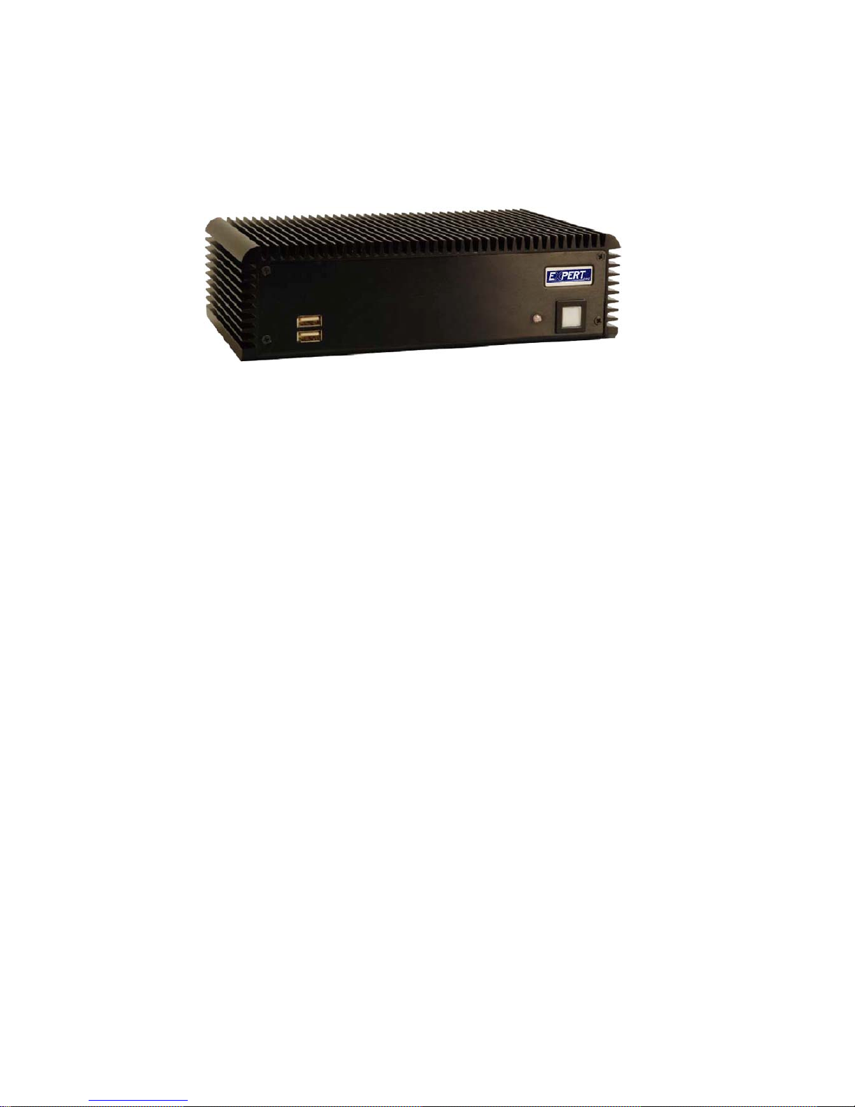
Figure 1-1: EX-9392B Series Embedded System
There are four EXPERT Intel® Atom™ based embedded solutions in the EX-9392B series.
All fanless motherboards have been optimized
for multimedia applications that require
minimum installation space. The EXPERT motherboard supports a full range of functions for an
AT/ATX-compatible industrial computer.
EX-9392B embedded subsystems are all capable of
supporting one 2.5” SATA hard disk drive. The EX-9392B-W models also have a built-in 802.11
b/g wireless module.
1.1.1 EX-9392B Benefits
The EX-9392B embedded system has the following benefits:
Easy installation saves installation time
Complete integration saves solution development time and cost
Secure storage with one SATA hard drive supported
Compact size saves space
Powerful preinstalled Intel® Atom™ N270 CPU and motherboard ensures
rigorous processing needs can be met
1.1.2 EX-9392B Features
The EX-9392B has the following features
RoHS compliant design
Fanless system
EX-9392B-ATOM Embedded System
Page 3
Built-in DC-to-DC power converter
1.6 GHz Intel® Atom™ N270 CPU supported
Dual GbE LAN for high speed network applications
One SATA hard drive supported
Wall mount and DIN mount supported.
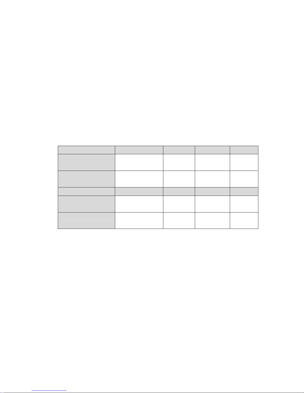
1.2 EX-9392B Model Variations
There are four models in the EX-9392B embedded system series. The EX-9392B series
supports 12V DC input and the EX-9392BWD series supports 9V~36V DC input. The four
models are listed in Table 1-1 below.
EX-9392B CPU Memory Power Wireless
-R10/1GB Intel® Atom™ N270 1 GB DDR 12V DC input
(55 W adaptor)
No
-W-R10/1GB Intel® Atom™ N270 1 GB DDR 12V DC input
(55 W adaptor)
Yes
EX-9392BWD CPU Memory Power Wireless
-R10/1GB Intel® Atom™ N270 1 GB DDR 9V~36V DC
input
No
-W-R10/1GB Intel® Atom™ N270 1 GB DDR 9V~36V DC
input
Yes
Table 1-1: Model Variations

EX-9392B-ATOM Embedded System
Page 4
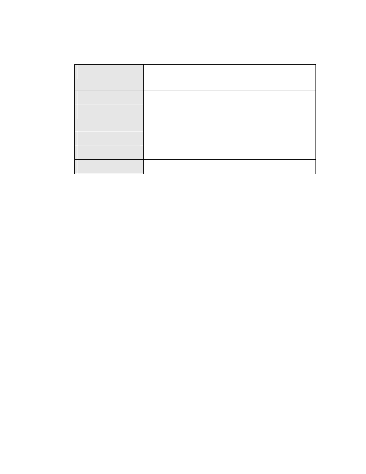
1.3 Technical Specifications
The specifications for the Intel based embedded systems are listed below.
EX-9392B
CPU
Preinstalled 1.6 GHz Intel® Atom™ Processor N270 with a
533 MHz FSB
System Chipset
Intel® 945GSE + ICH7-M
System Memory
Preinstalled 1.0 GB DDR2 SDRAM SO-DIMM (system max. 2 GB)
Ethernet
Dual Realtek RTL8111CP GbE controllers
Buit-in 802.11 b/g wireless module for the wireless models
Display
CRT integrated in Intel® 945GSE
USB
Four USB 2.0 ports
Serial Port
Six RS-232
Audio
One audio out
Storage
One 2.5” SATA hard drive supported
One internal CF card slot
Chassis Construction
Aluminum Alloy
Power Supply
Internal DC-to-DC power converter, input voltage:
12V DC or 9V – 36V (WD series models)
External power adapter, input voltage:
90V AC ~ 264V AC @ 47Hz ~ 63Hz, 55 W
Power Consumption
19 W
Operating Shock
Half-sine wave shock 3G; 11ms; 3 shocks per axis
Operating Vibration
MIL-STD-810F 514.5C-1 (HDD)
MIL-STD-810F 514.5C-2 (CF)
EX-9392B-ATOM Embedded System
Page 5
Operating temperature
-10ºC ~ 50ºC with HDD
-10ºC ~ 60ºC with CF card
Color
Black
Mounting
DIN mount
VESA MIS-D 100 wall mount
Weight (Net/Gross)
2.1 kg/3.9 kg
Dimensions (D x W x H)
132 mm x 229 mm x 64 mm
EMC
FCC Class A, CE
Table 1-2: Technical Specifications
EX-9392B-ATOM Embedded System
Page 6
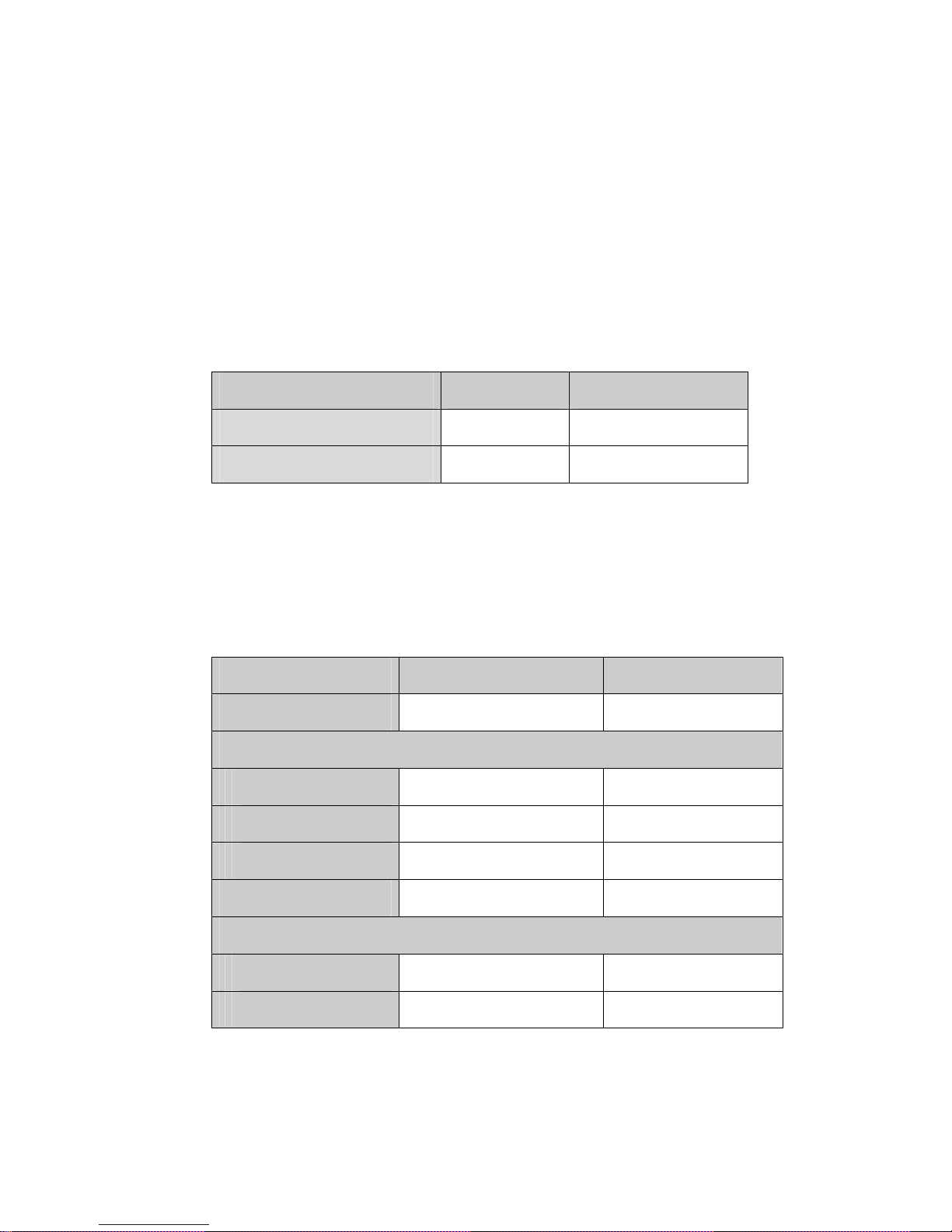
1.4 Power Module Specifications
1.4.1 Power Module Options
The EX-9392B embedded system supports either a 12V DC input or a 9V~36V DC input.
The input support depends on the power module installed in the system. The two power
modules are listed in Table 1-3:
Embedded System Power Module DC Input
EX-9392B Series
IDD-12250A 12V DC input
EX-9392BWD Series
IDD-936260A 9V~36V DC input
Table 1-3: EX-9392B Power Module Options
1.4.2 Power Module Specifications
The specifications for the IDD-12250A and IDD-936260A are shown in Table 1-4.
Model Name: IDD-12250A IDD-936260A
Input
12VDC 9VDC~36VDC
Output:
12V
5A (pass thru.) 3A (Max.)
5V
10A (Max.) 10A (Max.)
5VSB
0.5A (Max.) 0.5A (Max.)
Max. Total Output:
50W+60W (12V pass thru.) 60W
Performance Characteristics:
Noise & Ripple:
< 240mV < 240mV
Line Regulation:
< 20mV < 20mV
EX-9392B-ATOM Embedded System
Page 7
Load Regulation
<60mV <60mV
Efficiency:
Up to 90% Up to 90%
Dimensions:
40mm x 100mm 40mm x 100mm
Weight:
46g 58g
Operating Temperature:
-40°C~85°C -40°C~85°C
Table 1-4: DC-to-DC Power Module Specifications
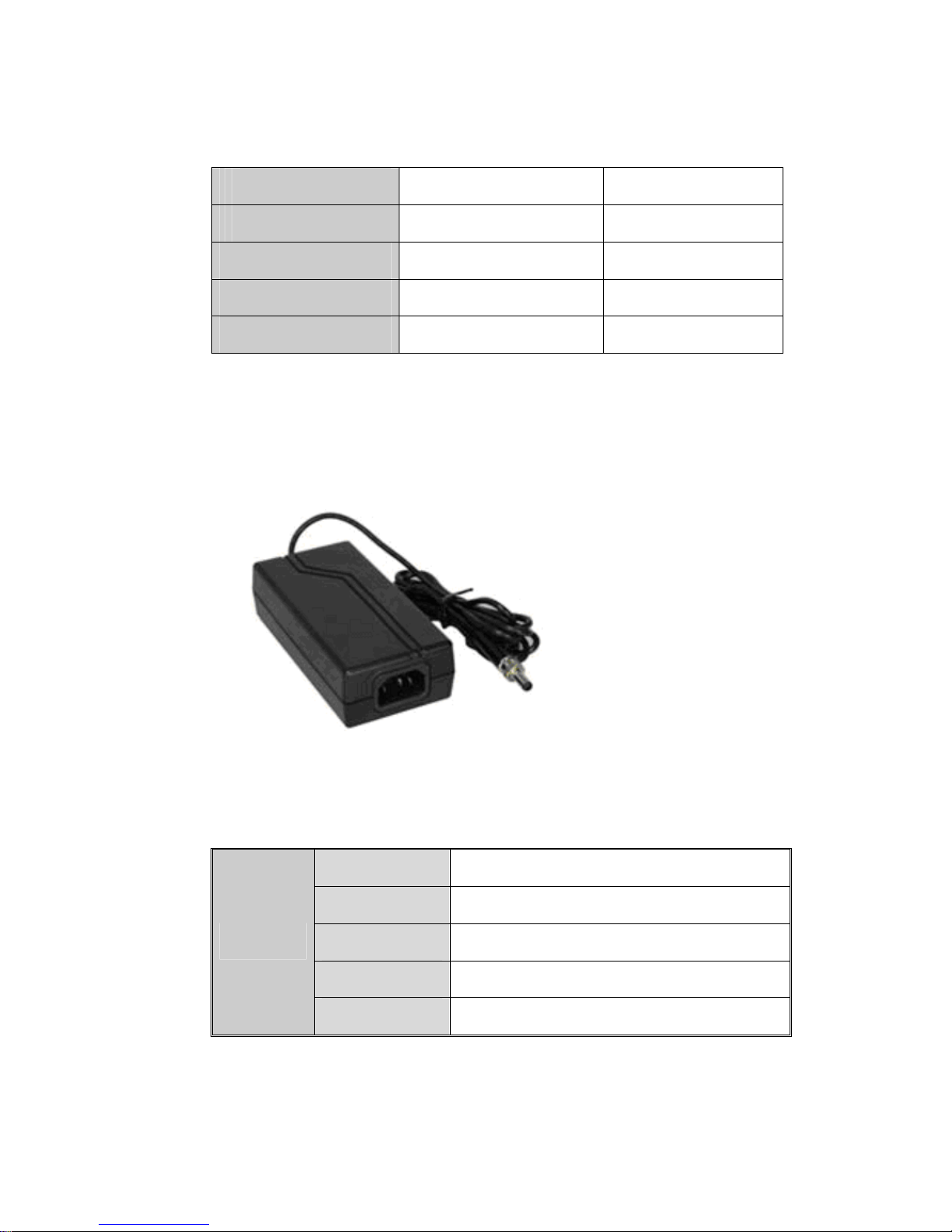
1.5 Power Adapter
The EX-9392B series models are shipped with a 55 W power adapter.
Figure 1-2: Power Adapter
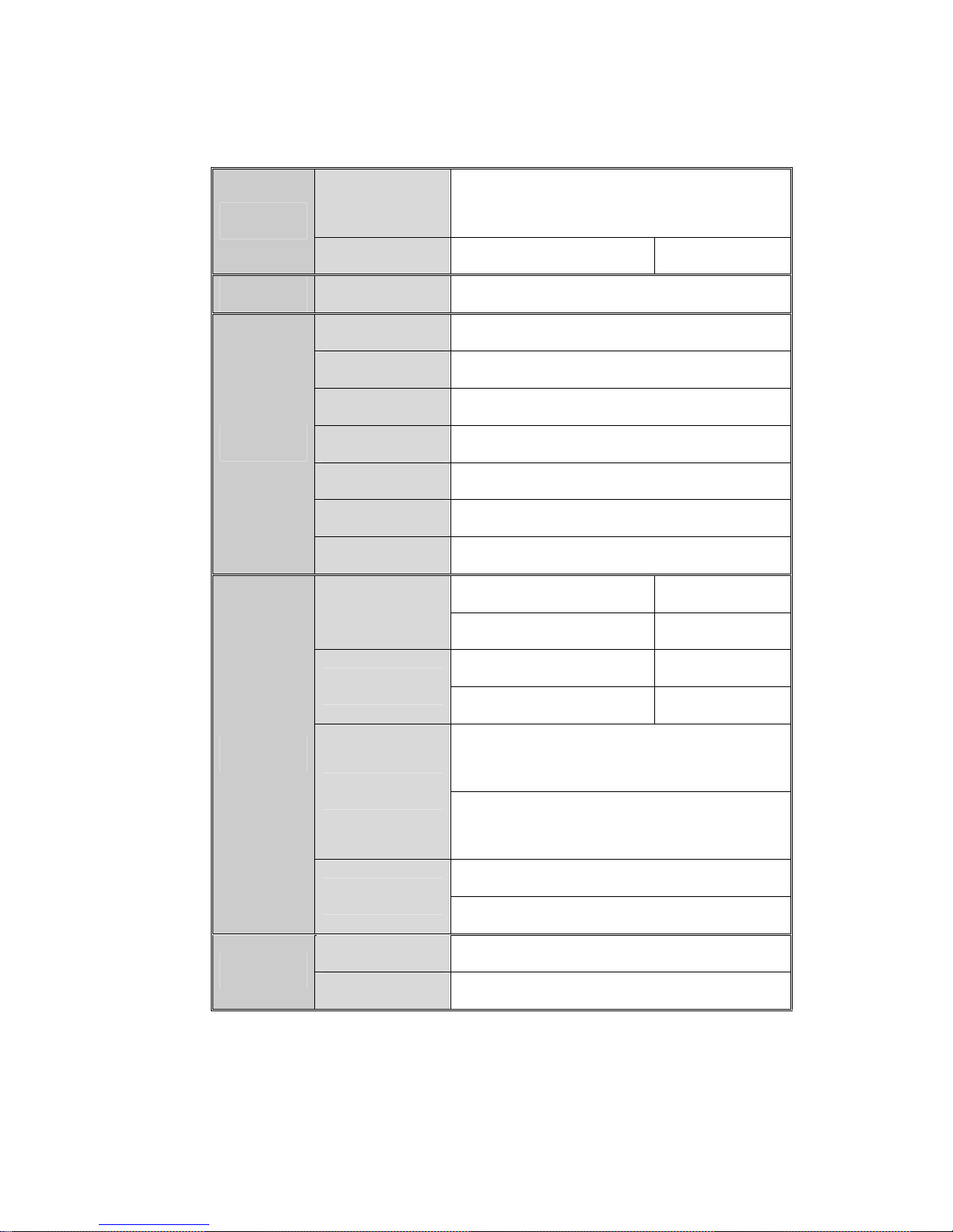
The specifications for the adapter are listed in Table 1-5:
Nominal
12.0V
Regulation
11.52V – 12.48V
Ripple/Noise
120mV
Min.
0A
Output
Max.
4.58A
EX-9392B-ATOM Embedded System
Page 8
Short Circuit
Output can be shorted without damage and
auto-recovery
Protection
Over-Voltage
Upper Trip Limit: 15V+/-1.5V
Time Hold Up
10ms
Min.
90V
Nominal
115V ~ 230V
Max.
264V
Frequency
47Hz ~ 63Hz
Inrush Current
80A Max. (cold start at 25ºC)
Steady Current
1.3Arms Max.
Input
Efficiency
80% (typical)
Operating 0ºC ~ 40ºC
Temperature
Storage -25ºC ~ 65ºC
Operating (non-condensing) 0% ~ 95%
Relative Humidity
Storage (non-condensing) 0% ~ 95%
Operating: 1G, 5Hz~500Hz, random vibration,
30mins/axis, 3 direction
Vibration
Storage: 2G, 5Hz~500Hz, random vibration,
30mins/axis, 3 direction
Operating: 10G, 11ms, Half-sine wave
Environment
Shock
Storage: 20G, 11ms, Half-sine wave
MTBF
100,000 hours of continuous operation at 25ºC
Reliability
Leakage Current
0.5mA max @264V
Table 1-5: Power Adapter Specifications

EX-9392B-ATOM Embedded System
Page 9
Chapter
2
2 Mechanical
Description

EX-9392B-ATOM Embedded System
Page 10
2.1 EX-9392B Mechanical Overview
The EX-9392B RoHS compliant, Intel® Atom™ fanless embedded system features
industrial grade components that offer longer operating life, high shock/vibration
resistance and endurance over a wide temperature range. The EX-9392B combines these
features in an aluminum enclosure designed for space critical applications that require low
power consumption. Featuring two LAN, four USB, six serial communication ports, as well
as audio, and VGA, the EX-9392B offers system integrators and developers the best
selection of robust and high performance computing system platforms. An internal bracket
supports one 2.5” SATA hard drives.
2.2 Physical Dimensions
The physical dimensions of the EX-9392B embedded systems are listed below.
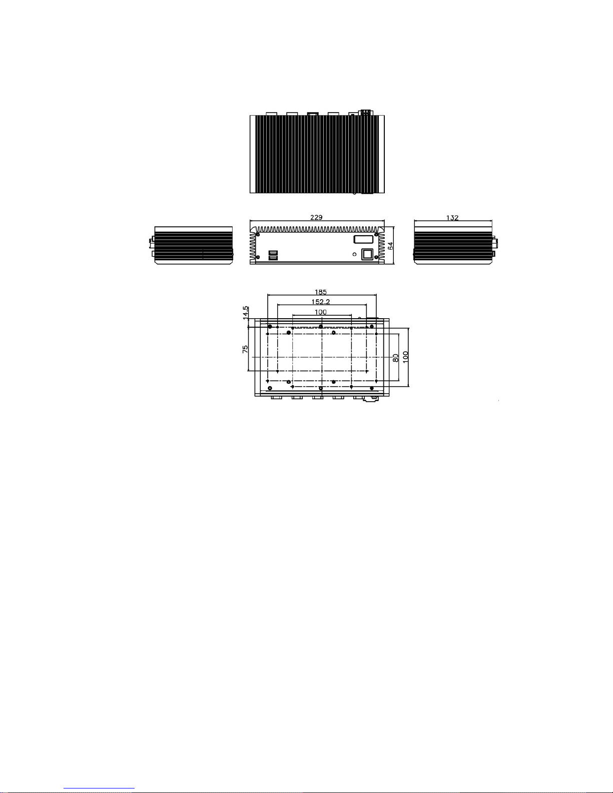
2.2.1 EX-9392B Dimensions
The dimensions of the EX-9392B are listed below and shown in Figure 2-1.
Height: 64.00 mm
Width
: 229.00 mm
Length: 132.00 mm
EX-9392B-ATOM Embedded System
Page 11
Figure 2-1: EX-9392B Dimensions (mm)
2.2.2 Motherboard Dimensions
The EXPERT series dimension are listed below and shown in Figure 2-2.
Length: 145.00 mm
Width: 102.00 mm

EX-9392B-ATOM Embedded System
Page 12
Figure 2-2: EXPERT SBC Dimensions (mm)
2.2.3 Power Module Dimensions
The power module dimensions are listed below and shown in Figure 2-3.
Length: 100.00 mm
Width: 40.00 mm
Figure 2-3: Power Module Dimensions (mm)
EX-9392B-ATOM Embedded System
Page 13
2.3 External Overview
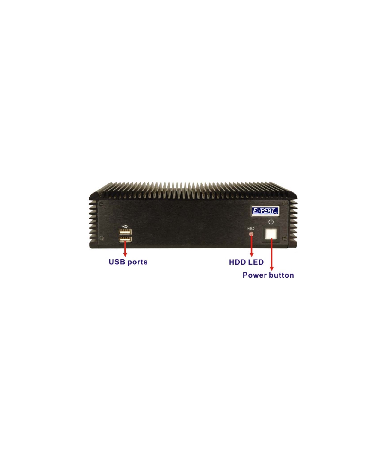
2.3.1 Front Panel
The EX-9392B front panel contains:
2 x USB port connectors
1 x HDD LED indicator
1 x Power button
An overview of the front panel is shown in Figure 2-4 below.
Figure 2-4: EX-9392B Front Panel
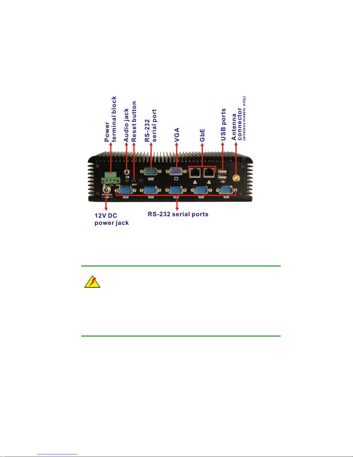
2.3.2 Rear Panel
The rear panel of the EX-9392B provides access to the following external I/O connectors.
2 x USB port connectors
2 x RJ-45 Ethernet connector
1 x VGA connector
6 x RS-232 serial ports
1 x Speaker out
1 x 3-pin power terminal block
1 x 12V DC power jack
EX-9392B-ATOM Embedded System
Page 14
1 x Wireless antenna connector (for wireless models only)
An overview of the rear panel is shown in Figure 2-5.
Figure 2-5: EX-9392B Rear Panel
2.3.3 Bottom Surface
WARNING:
Never remove the bottom access panel from the chassis while power is still
being fed into the system. Before removing the bottom access panel, make
sure the system has been turned off and all power connectors unplugged.
The bottom surface of the EX-9392B contains the retention screw holes for the VESA
MIS-D 100 wall-mount kit, two-side mounting brackets and DIN mount bracket.
 Loading...