

Page 1
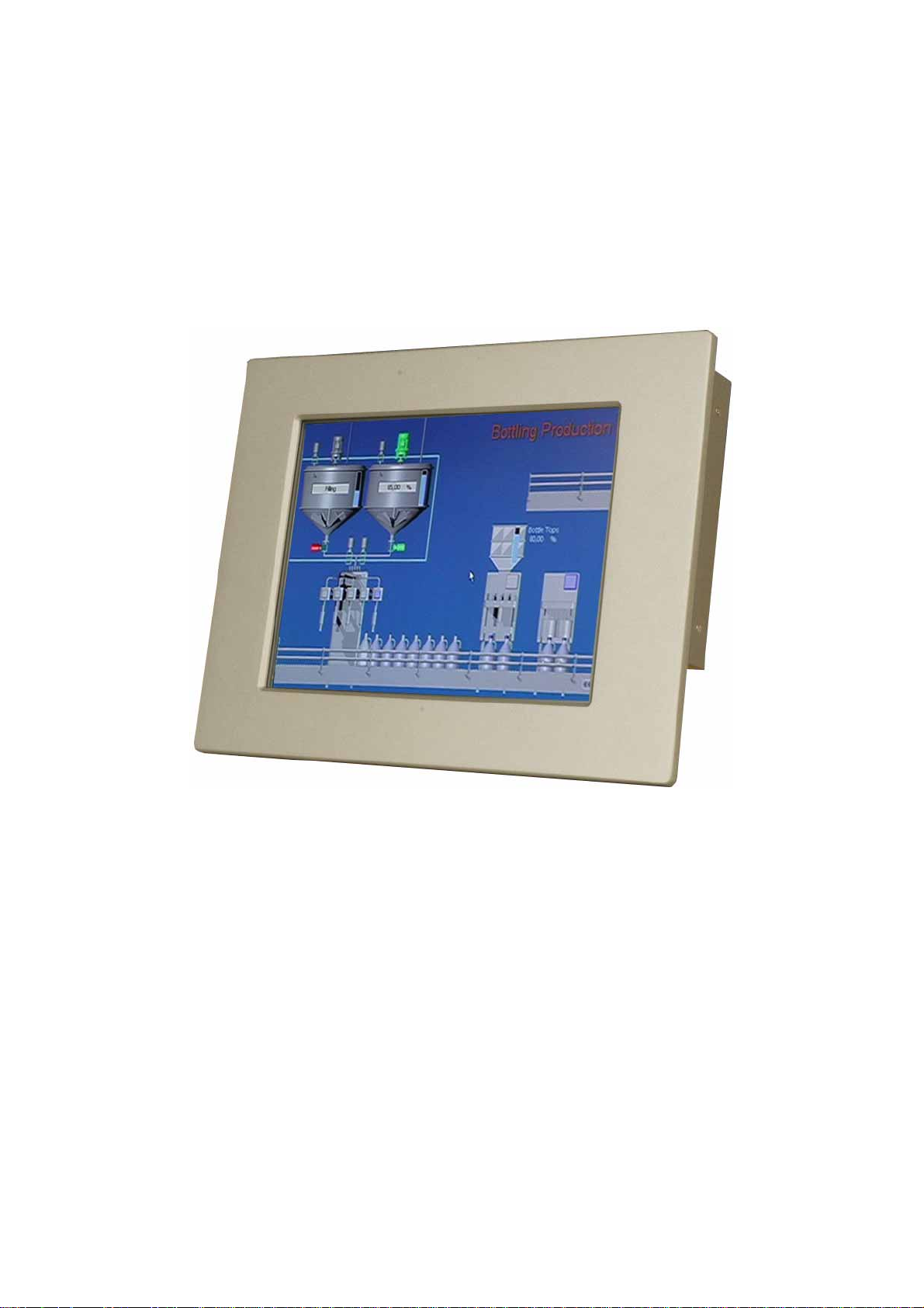
EX-93821/EX-93823 Flat Panel PC
Page 1
Page 2

EX-93821/EX-93823 Flat Panel PC
Revision
Date Version Changes
2008-04 1.02 Added EX-93821GHS high luminance panel information
2007-08 1.01 Modified some specs errors
2007-07 1.00 Initial release
Page 2
Page 3

Copyright
COPYRIGHT NOTICE
The information in this document is subject to change without prior notice in order to
improve reliability, design and function and does not represent a commitment on the part
of the manufacturer.
In no event will the manufacturer be liable for direct, indirect, special, incidental, or
consequential damages arising out of the use or inability to use the product or
documentation, even if advised of the possibility of such damages.
This document contains proprietary information protected by copyright. All rights are
reserved. No part of this manual may be reproduced by any mechanical, electronic, or
other means in any form without prior written permission of the manufacturer.
TRADEMARKS
All registered trademarks and product names mentioned herein are used for identification
purposes only and may be trademarks and/or registered trademarks of their respective
owners.
Page 3
Page 4
EX-93821/EX-93823 Flat Panel PC
Manual Conventions
WARNING!
Warnings appear where overlooked details may cause damage to the equipment or result
in personal injury. Warnings should be taken seriously. Warnings are easy to recognize.
The word “warning” is written as “WARNING,” both capitalized and bold and is followed by
text. The text is the warning message. A warning message is shown below:
WARNING:
This is an example of a warning message. Failure to adhere to warning
messages may result in permanent damage to the
EX-93821/EX-93823 or personal injury to the user. Please take
warning messages seriously.
CAUTION!
Cautionary messages should also be heeded to help reduce the chance of losing data or
damaging the EX-93821/EX-93823. Cautions are easy to recognize. The word “caution” is
written as “CAUTION,” both capitalized and bold and is followed. The italicized text is the
cautionary message. A caution message is shown below:
Page 4
Page 5
CAUTION:
This is an example of a caution message. Failure to adhere to cautions
messages may result in permanent damage to the
EX-93821/EX-93823. Please take caution messages seriously.
NOTE:
These messages inform the reader of essential but non-critical information. These
messages should be read carefully as any directions or instructions contained therein can
help avoid making mistakes. Notes are easy to recognize. The word “note” is written as
“NOTE,” both capitalized and bold and is followed by text. The text is the cautionary
message. A note message is shown below:
NOTE:
This is an example of a note message. Notes should always be read.
Notes contain critical information about the EX-93821/EX-93823.
Please take note messages seriously.
Page 5
Page 6

EX-93821/EX-93823 Flat Panel PC
Packing List
NOTE:
If any of the components listed in the checklist below are missing,
please do not proceed with the installation. Contact the TOPSCCC
reseller or vendor you purchased the EX-93821/EX-93823 from or
contact an TOPSCCC sales representative directly. To contact an
TOPSCCC sales representative, please send an email to
The items listed below should all be included in the EX-93821/EX-93823 package.
1 x EX-93821/EX-93823 flat panel PC
1 x Power cord
1 x 45W power adapter
1 x Screw kit
1 x Jumper pack
1 x PS/2 keyboard/mouse Y cable
1 x User Manual and driver CD
1 x Panel mounting kit
1 x Wall mounting kit
1 x Rack mounting kit (optional)
1 x Arm mounting kit (optional)
1 x Stand mounting kit (optional)
Page 6
Images of the above items are shown in
Chapter 3
.
Page 7

Table of Contents
1 INTRODUCTION................................................................................................... 13
1.1 EX-93821/EX-93823 F
LAT PANEL PC OVERVIEW .................................................. 14
1.1.1 Model Variation.................... .. .............................................................. ............ 14
1.1.2 Applications ........................................... ........ ........... ........ ........... .......... ........ ..14
1.1.3 Standar d Features............................................................................................15
1.2 E
XTERNAL OVERVIEW ............................................................................................. 15
1.2.1 General Description..................... ..... ... ..... ... ..... ..... ... ..... ... ..... ...... .. ...... ..... ... ....15
1.2.2 Front P anel ............................................ ................................ ..........................15
1.2.3 Rear Panel ........................................................................................ ............... 16
1.2.4 Top Panel ....................... ........ ........... ........ ........... ........ .......... ........ ........... .......16
1.2.5 Bottom Panel.................................................................. ................................ ..17
1.2.6 Side Panel .............................................. ... ..... ... ..... ...... .. ...... .. ...... .. ...... ..... ... ....18
1.3 I
NTERNAL OVERVIEW............................................................................................... 19
PECIFICATIONS ....................................................................................................... 19
1.4 S
1.4.1 Prei nstalled Hardware Components............................................ .. .................. 19
1.4.2 System Specifications..................................... ...... .. ...... ..... ... ..... ... ..... ... ..... ... ....19
1.4.3 Motherboard Specifications............................................................................. 21
1.4.4 Flat Panel Screen Spec ifications ................................................. .................... 22
1.4.4.1 EX-93821 Flat Panel Screen Specifications ............................................. 22
1.4.4.2 EX-93823 Flat Panel Screen Specifications ............................................. 23
1.5 D
IMENSIONS ............................................................................................................ 25
1.5.1 EX-93821 Dimensions ................................................. .. .................................. 25
1.5.2 EX-93823 Dimensions ................................................. .. .................................. 26
2 MOTHERBOARD..................................................................................................27
NTRODUCTION ........................................................................................................ 28
2.1 I
2.2 CPU S
2.2.1 AMD
2.2.2 AMD
2.3 S
2.4 G
UPPORT.......................................................................................................... 28
®
Geode™ LX 800 500MHz Specifications.............................................28
®
Geode™ LX 800 500MHz Power Management...................................29
YSTEM CHIPSET ..................................................................................................... 29
RAPHICS SUPPORT ................................................................................................. 30
Page 7
Page 8

EX-93821/EX-93823 Flat Panel PC
2.5 E
THERNET CONTROLLER SPECIFICATIONS ............................................................... 32
2.5.1 Overview................................ ...... ..... ... ..... ... ..... ..... ... ..... ...... .. ...... .. ...... ..... ... ....32
2.5.2 Features ............................................................................... ............................32
2.6 P
ERIPHERAL DEVICE INTERFACES, CONNECTORS, AND SLOTS................................. 33
2.6.1 OEM Options............................... .. ...... ..... ... ..... ... ..... ... ..... ..... ... ..... ... ..... ...... .. ..33
2.6.2 Internal Slots.................................................................................................... 33
2.6.3 Internal Peripheral Device Connectors......................................... .................. 33
2.6.4 External Peripheral Device Connectors.......................................................... 34
3 INST ALLA TIO N AND CONFIGURATION .......................................................35
3.1 INSTALLATION PRECAUTIONS................................................................................... 36
REINSTALLED COMPONENTS .................................................................................. 36
3.2 P
3.3 I
NSTALLATION AND CONFIGURATION STEPS ............................................................. 36
NPACKING.............................................................................................................. 37
3.4 U
3.4.1 Packing List ......................................................... .. .......................................... 38
3.4.2 Optional Items...................................... ..... ... ..... ... ..... ..... ... ..... ... ..... ...... .. ...... ....39
3.5 C
OMPACTFLASH® CARD INSTALLATION.................................................................. 40
EMOVE THE BACK COVER...................................................................................... 41
3.6 R
UMPER SETTINGS.................................................................................................... 42
3.7 J
3.7.1 AT/ATX Power Select........................................................... ........ ........ .......... ..42
3.7.2 COM3 Pin-9 Signal Select Jumper Settings............................................. ....... 43
3.7.3 COM1 and COM2 Pin- 9 Signal Select Jumper Settings ................................. 44
3.7.4 COM2 Select Jumper Settings .........................................................................45
3.8 HDD I
3.9 M
3.10 M
NSTALLATION ................................................................................................ 47
EMORY MODULE INSTALLATION ........................................................................... 48
OUNTING THE SYSTEM ........................................................................................ 49
3.10.1 Wall Mounting......................... ........... .......... ........ ........... ........... ........ .......... ..49
3.10.2 Panel Mounting..............................................................................................52
3.10.3 Arm Mounting.............................. ........... ........... ........ .......... ........... ........ .......54
3.10.4 Cabinet and Rack Installation ................................ ................................... .... 55
3.11 R
EAR PANEL CONNECTORS .................................................................................... 57
3.11.1 LCD Panel Connection.................................................................................. 57
3.11.2 Ethernet Connection....................................................................................... 57
3.11.3 USB Connection............................................................................................. 58
3.11.4 Keyboard and Mouse Connection.................................................................. 58
Page 8
Page 9

3.12 S
YSTEM MAINTENANCE......................................................................................... 58
4 GASKET REPLACEMENT.............................................. ................................ .... 59
4.1 GASKET REPLACEMENT ........................................................................................... 60
5 AMI BIOS SETUP.............................................. ..... ... ..... ..... ... ..... ...... .. ...... ..... ... ....61
5.1 INTRODUCTION ........................................................................................................ 62
5.1.1 Starti ng Setup.................................................... ..... ... ..... ... ..... ...... .. ...... .. ...... ....62
5.1.2 Using Setup.................... ...... .. ...... .. ...... ..... ... ..... ... ..... ..... ... ..... ...... .. ...... .. ...... ....62
5.1.3 Getting Help...................................................... ..... ...... .. ...... .. ...... ..... ... ..... ... ....63
5.1.4 Main BIOS Menu ................................................. ................................ ............ 63
TANDARD CMOS FEATURES.................................................................................. 65
5.2 S
5.2.1 IDE Primary Master/Slave ............................................ .................................. 68
5.3 A
DVANCED BIOS FEATURES.................................................................................... 70
DVANCED CHIPSET FEATURES................................................................................ 76
5.4 A
5.4.1 Flat Panel Configuration.................................................................................79
5.5 I
NTEGRATED PERIPHERALS ...................................................................................... 82
OWER MANAGEMENT SETUP.................................................................................. 87
5.6 P
NP/PCI CONFIGURATIONS ..................................................................................... 94
5.7 P
5.8 PC H
EALTH STATUS ................................................................................................. 97
A SAFETY PRECAUTIONS..................................................................................... 99
AFETY PRECAUTIONS .......................................................................................... 100
A.1 S
A.1.1 General Safety Precautions........................................................................... 100
A.1.2 Anti-static Precautions................................ .......... ........... ........ ........... ..........101
A.2 M
AINTENANCE AND CLEANING PRECAUTIONS...................................................... 101
A.2.1 Maintenance and Cleaning............................................................................101
A.2.2 Cleaning Tools............................................................................................... 102
B BIOS CONFIGURATION OPTIONS...................................................... ..... ... ..103
B.1 BIOS C
ONFIGURATION OPTIONS........................................................................... 104
C SOFTWARE DRIVERS....................................................................................... 107
C.1 INTRODUCTION ...................................................................................................... 108
RIVER INSTALLATION .......................................................................................... 108
C.2 D
OUCH PANEL DRIVER CONFIGURATION ................................................................115
C.3 T
Page 9
Page 10

EX-93821/EX-93823 Flat Panel PC
D HAZARDOUS MATERIALS DISCLOSURE...................................... ... ...........117
AZARDOUS MAT E RI A L DISCLOSURE TABLE FOR IPB PRODUCTS CERTIFIED AS
D.1 H
ROHS COMPLIANT UNDER 2002/95/EC WITHOUT MERCURY......................................118
E INDEX.................................................................................................................... 121
Page 10
Page 11

List of Figures
Figure 1-1: EX-93821/EX-93823 Front View ..............................................................16
Figure 1-2: EX-93821 Rear View......................................................... ........................16
Figure 1-3: EX-93821 Top View..................................................................................17
Figure 1-4: EX-93821 Bottom View............................................................................18
Figure 1-5: EX-93823 Bottom View............................................................................18
Figure 1-6: EX-93821 Side View.................................................................................19
Figure 1-7: EX-93821 Dimensions (units in mm)......................................................25
Figure 1-8: EX-93823 Dimensions (units in mm)......................................................26
Figure 3-1: CF Card Installation.......................................... .......................................41
Figure 3-2: EX-93821 Back Cover Retention Screws...............................................41
Figure 3-3: AT/ATX Power Select Jumper Location................................................43
Figure 3-4: COM3 Pin-9 Signal Select Jumper Location.........................................44
Figure 3-5: COM1 and COM2 Pin-9 Signal Select Jumper Location......................45
Figure 3-6: COM2 Select Jumper Location...............................................................46
Figure 3-7: HDD Bracket Retention Screws .............................................................47
Figure 3-8: EX-93821/EX-93823 HDD Bracket Retention Screws ...........................47
Figure 3-9: EX-93821/EX-93823 SO-DIMM Socket Location....................................48
Figure 3-10: SO-DIMM Module Installation...............................................................49
Figure 3-11: Wall-mounting Bracket..........................................................................50
Figure 3-12: Mount the Chassis.................................................................................51
Figure 3-13: Secure the Chassis................................................................................52
Figure 3-14: EX-93821 Panel Opening.......................................................................53
Figure 3-15: EX-93823 Panel Opening.......................................................................53
Figure 3-16: Tighten the Panel Mounting Clamp Screws........................................54
Figure 3-17: Arm Mounting Retention Screw Holes................................................55
Figure 3-18: Secure the EX-93821/EX-93823 Rack/Cabinet Bracket......................56
Figure 3-19: Install into a Rack/Cabinet....................................................................57
Figure 4-1: Gasket Replacement ...............................................................................60
Page 11
Page 12

EX-93821/EX-93823 Flat Panel PC
List of Tables
Table 1-1: EX-93821 and EX-93823 Model Variations..............................................14
Table 1-2: EX-93821/EX-93823 Specifications..........................................................21
Table 1-3: Motherboard Specifications.....................................................................22
Table 1-4: EX-93821 TFT LCD Monitor Specifications.............................................23
Table 1-5: EX-93823 TFT LCD Monitor Specifications.............................................24
Table 2-1: Geode LX Graphics Features...................................................................31
Table 3-1: Package List Contents..............................................................................39
Table 3-2: Optional Items ...........................................................................................40
Table 3-3: Jumpers......................................................................................................42
Table 3-4: AT/ATX Power Select Jumper Settings...................................................43
Table 3-5: COM3 Pin-9 Signal Select Jumper Settings ...........................................44
Table 3-6: COM1 and COM2 Pin-9 Signal Select Jumper Settings ........................45
Table 3-7: COM2 Select Jumper Settings (JP5).......................................................46
Table 3-8: COM2 Select Jumper Settings (JP6).......................................................46
Table 5-1: BIOS Navigation Keys...............................................................................63
Page 12
Page 13

Chapter
1
1 Introduction
Page 13
Page 14
EX-93821/EX-93823 Flat Panel PC
1.1 EX-93821/EX-93823 Flat Panel PC Overview
The EX-93821/EX-93823 flat panel PC is a flexible, multi-functional flat panel PC that can
be applied in diverse operational environments and implemented in multi-faceted
applications. The EX-93821/EX-93823 comes fully kitted with a high-performance
motherboard and a host of other peripheral interface connectors. The
EX-93821/EX-93823 is designed for ease of use and easy installation.
1.1.1 Model Variation
Six TOPSCCC EX-93821/EX-93823 models are available. The models are listed in Table
1-1.
EX-93821GS CPU LCD Brightness Wireless Module
/EXMB-LX-800/T-R AMD® Geode LX 800 10.4” 230 cd/m2 No
/EXMB-LX-800/W T-R AMD® Geode LX 800 10.4” 230 cd/m2 Yes
EX-93821GHS CPU LCD Brightness Wireless Module
/EXMB-LX-800/T-R AMD® Geode LX 800 10.4” 400 cd/m2 No
/EXMB-LX-800/W T-R AMD® Geode LX 800 10.4” 400 cd/m2 Yes
EX-93823GS CPU LCD Touch screen Wireless Module
/EXMB-LX-800/T-R AMD® Geode LX 800 12.1” 450 cd/m2 No
/EXMB-LX-800/WT-R AMD® Geode LX 800 12.1” 450 cd/m2 Yes
Table 1-1: EX-93821 and EX-93823 Model Variations
1.1.2 Applications
The EX-93821/EX-93823 flat panel PC is designed for rigorous industrial environments
where it may be exposed to both heat and moisture. Its durability and strength also makes
it an ideal choice for public access computers. Some possible applications include:
Automated manufacturing processes
Page 14
Public information gathering point
Page 15

1.1.3 Standard Features
Some of the standard features of the EX-93821 and EX-93823 flat panel PC include:
Fanless and low power consumption
AMD® Geode
DDR 333/400 SO-DIMM memory support up to 1GB
Aluminum die-casting IP 65 industrial panel
Resistive type touch screen preinstalled
Dual 10/100Mbps Ethernet support
One CompactFlash
Optional 802.11b/g wireless LAN module
Simplified installation process
RoHS compliance
1.2 External Overview
1.2.1 General Description
TM
LX 800 (500MHz) processor
®
Type II socket support
The EX-93821/EX-93823 flat panel PC is a rectangular cubic structure that comprises of a
screen, rear panel, top panel, bottom panel and two side panels (left and right). An
aluminum frame surrounds the front screen. The rear panel provides screw holes for a
wall-mounting bracket. The bottom panel provides access to external interface connectors
that include LAN, USB 2.0, audio, VGA port, serial ports, keyboard/mouse connector and
power switch.
1.2.2 Front Panel
The front side of the EX-93821/EX-93823 is a flat panel TFT LCD screen surrounded by
an aluminum frame (Figure 1-1).
Page 15
Page 16
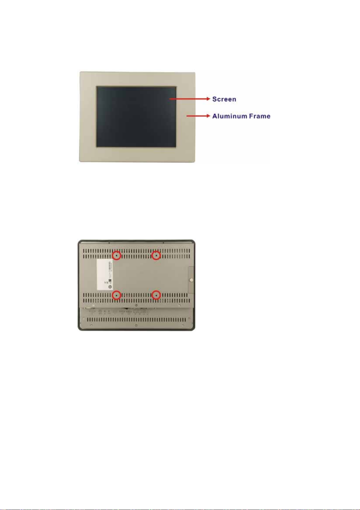
Figure 1-1: EX-93821/EX-93823 Front View
1.2.3 Rear Panel
The rear panel provides access to ventilation vents and retention screw holes that support
EX-93821/EX-93823 Flat Panel PC
the wall mounting. Refer to
Figure 1-2
.
Figure 1-2: EX-93821 Rear View
1.2.4 Top Panel
The top panel of EX-93821/EX-93823 provides access to three retention screws that
support to secure the back cover to the chassis. A connector reserved for wireless LAN
Page 16
antenna for EX-93821/EXMB-LX-800/WT-R or EX-93823/EXMB-LX-800/WT-R model is
also located in the top panel. The retention screws and antenna connector are circled in
Figure 1-3 below.
Page 17
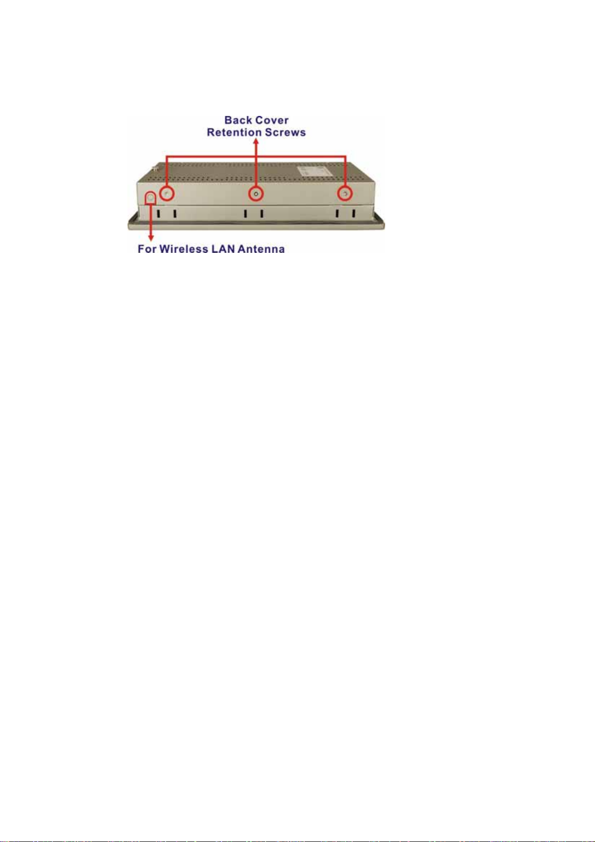
Figure 1-3: EX-93821 Top View
1.2.5 Bottom Panel
The bottom panel of the EX-93821/EX-93823 has the following I/O interfaces
(
Figure 1-4
):
1 x PS/2 keyboard/mouse connector
1 x Audio jack
1 x VGA connector
1 x AC power adapter connector
1 x Power switch
2 x Serial port (COM) connectors
2 x RJ-45 10/100Mbps Ethernet connectors
2 x USB 2.0 connectors (EX-93821)
4 x USB 2.0 connectors (EX-93823)
1 x Reset button
Page 17
Page 18
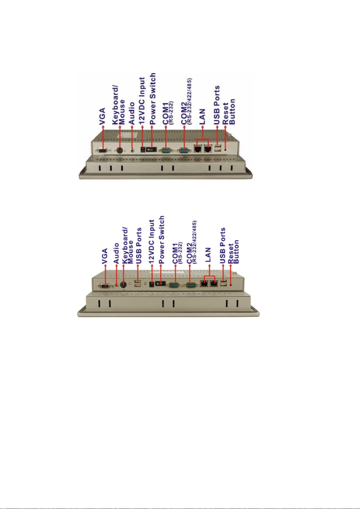
EX-93821/EX-93823 Flat Panel PC
Figure 1-4: EX-93821 Bottom View
Figure 1-5: EX-93823 Bottom View
1.2.6 Side Panel
The EX-93821/93823 has two side panels, left panel and right panel. Both side panels
have retention screw holes that secure the back cover to the chassis. The left side panel
also provides access to a CF card slot. Refer to Figure 1-6.
Page 18
Page 19
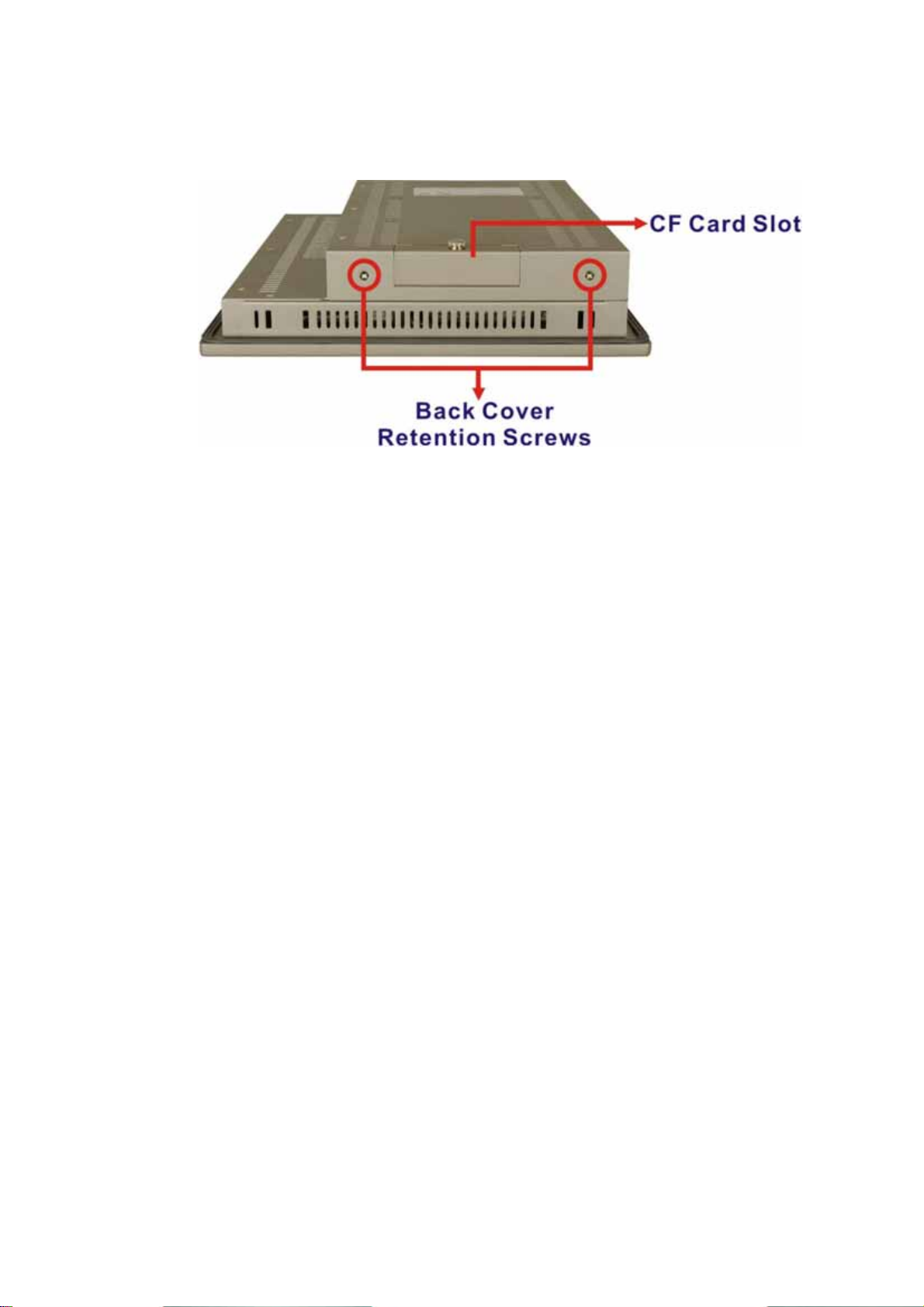
Figure 1-6: EX-93821 Side View
1.3 Internal Overview
The EX-93821/2708 internal components are configured in a two level format. The
motherboard and 2.5” HDD are installed on a metal sheet that protects the rear of the TFT
LCD screen. Below the metal sheet is a circuit board that is connected to the screen and
the motherboard.
1.4 Specifications
1.4.1 Preinstalled Hardware Components
The EX-93821/EX-93823 flat panel PC has the following preinstalled components:
1 x Motherboard
1 x Inverter
1 x TFT LCD screen
The technical specifications for these components and the system are shown in the
sections below.
1.4.2 System Specifications
The technical specifications for the EX-93821 and EX-93823 systems are listed in
Table 1-2.
Page 19
Page 20
EX-93821/EX-93823 Flat Panel PC
SPECIFICATION EX-93821 EX-93823
Front Panel
Chassis
LCD Panel
Resolution
Brightness
Contrast Ratio
Viewing Angle (H-V)
Backlight MTBF
Touch Screen
Drive Bay
I/O
Aluminum Front Panel
Heavy-duty Steel
10.4” TFT LCD 12.1” TFT LCD
800 x 600 (SVGA) 1024 x 768 (XGA)
230 cd/m2 or 400 cd/m2 450 cd/m2
500:1 700:1
140/120 160/160
30,000 hrs or 50,000 hrs 50,000 hrs
5-wire resistive type touch screen
One 2.5” IDE HDD bay
2 x USB 2.0 ports
1 x keyboard/mouse port
1 x VGA port
4 x USB 2.0 ports
1 x keyboard/mouse port
1 x VGA port
Page 20
Power
Mounting Feature
Color
Operating Temper ature
Storage Temperature
2 x LAN
1 x RS-232
1 x RS-232/422/485
1 x Audio jack
1 x IDE
45W AC adapter
-Input: 100-240VAC @ 47-63 Hz
-Output voltage: 12VDC
Panel, Wall, Arm, Stand or Rack
Silver (PANTONE PMS-8001)
0ºC ~50ºC
-20ºC ~60ºC
2 x LAN
1 x RS-232
1 x RS-232/422/485
1 x Audio jack
1 x IDE
Page 21
SPECIFICATION EX-93821 EX-93823
Relative Humidity
Vibration
5% ~ 95%@60ºC, non-condensing
5Hz - 17Hz, 0.1” double amplitude displacement.
17Hz - 640Hz, 1.5G acceleration, peak to peak.
Shock
Dimension (W x H x D)
Net/Gross Weight
Front Panel Protection
Certificate
10G Acceleration, peak to peak (11ms)
311.5mm x 242mm x 57mm 340mm x 260mm x 65.4mm
2.7kg/4.9kg 3.9kg/5.4kg
IP 65 compliant
Meets CE/FCC
Table 1-2: EX-93821/EX-93823 Specifications
1.4.3 Motherboard Specifications
The EX-93821 and EX-93823 both come with an EXMB-LX 800 motherboard. The
technical specifications of the motherboard are listed in Table 1-3.
Specification EXMB-LX 800
®
AMD
CPU
Southbridge Chipset
Display
Memory
Geode™ LX 800 (500Mhz)
®
AMD
Geode™ CS5536
CRT integrated in AMD
24-bit TTL integrated in AMD
®
Geode™ LX 800
®
Geode™ LX 800
Supports one 1GB DDR 333/400 200-pin SO-DIMM
SDRAM module
Extension
BIOS
SSD
One mini PCI slot (for wireless LAN module)
Award BIOS
CF Type II
Page 21
Page 22
EX-93821/EX-93823 Flat Panel PC
Super I/O
Audio
LAN
COM
IDE
Touch Screen Controller
Power Supply
Dimensions
Table 1-3: Motherboard Specifications
N/A for legacy free
AC'97 Codec Realtek ALC203, AMP 1-2W
Dual RTL8100C 10/100Base-T Ethernet controllers
One RS-232 serial port
One Rs-232/422/485 serial port
One 44-pin IDE connects to two IDE devices
DMC9000
12V ATX power support
102mm x 186mm
1.4.4 Flat Panel Screen Specifications
1.4.4.1 EX-93821 Flat Panel Screen Specifications
The EX-93821 comes with a TFT LCD monitor at the front of the flat panel PC (see Figure
1-1). The specifications for the EX-93821 LCD monitor are shown in Table 1-4 below.
SPECIFICATION GS Models GHS Models
Model
Size
Resolution
Active Area (mm)
Pixel Pitch (mm)
LCD Color
View Angel (H/V)
Brightness (cd/m2)
AUO-G104SN03 Toshiba-LTA104D182F
10.4” 10.4”
800 x 600 (SVGA) 800 x 600 (SVGA)
211.2 x 158.4 211.2 x 158.4
0.264 0.264
Native 262K colors 256K colors
140/120 120/100
230 400
Page 22
Page 23
SPECIFICATION GS Models GHS Models
Contrast Ratio
Response Time (ms)
Supply Voltage (V)
Backlight
Outline Dimensions (mm)
Backlight MTBF (hrs.)
Table 1-4: EX-93821 TFT LCD Monitor Specifications
500:1 500:1
35 (at 25°C) 6(Tr) / 17(Tf)
3.3 3.3
1 CCFL 2 CCFL
236.0 x 174.0 x 5.6 242.0 x 178.45 x 13.2
30,000 50,000
1.4.4.2 EX-93823 Flat Panel Screen Specifications
The EX-93823 comes with a TFT LCD monitor at the front of the flat panel PC (see Figure
). The specifications for the EX-93823 LCD monitor are shown in
1-1
Table 1-5
below.
SPECIFICATION EX-93823
Model
Size
Resolution
Active Area (mm)
Pixel Pitch (mm)
LCD Color
View Angel (H/V)
Brightness (cd/m2)
Contrast Ratio
Response Time (ms)
CMO-G121X1-L01
12.1”
1024 x 768 (XGA)
245.76 x 184.32
0.240 x 0.240
Native 262K colors
160/160
450
700:1
6(Tr) / 17(Tf)
Page 23
Page 24
EX-93821/EX-93823 Flat Panel PC
SPECIFICATION EX-93823
Power Consumption (W)
Supply Voltage (V)
Backlight
Outline Dimensions (mm)
Backlight MTBF (hrs.)
Table 1-5: EX-93823 TFT LCD Monitor Specifications
4
3.3
2 CCFL
260 x 204 x 12.2
50000
Page 24
Page 25
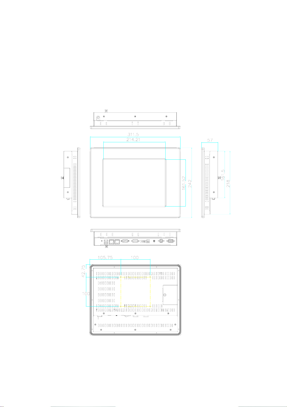
1.5 Dimensions
1.5.1 EX-93821 Dimensions
The dimensions of the EX-93821 flat panel PC are shown in Figure 1-7 below.
Figure 1-7: EX-93821 Dimensions (units in mm)
Page 25
Page 26
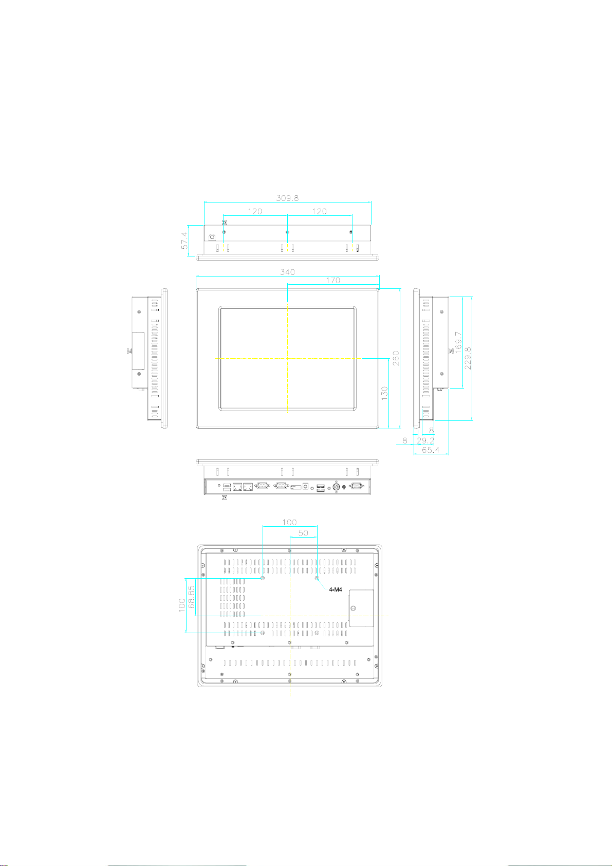
1.5.2 EX-93823 Dimensions
The dimensions of the EX-93823 flat panel PC are shown in Figure 1-8 below.
EX-93821/EX-93823 Flat Panel PC
Figure 1-8: EX-93823 Dimensions (units in mm)
Page 26
Page 27

Chapter
2
2 Motherboard
Page 27
Page 28

2.1 Introduction
The EX-93821 and EX-93823 flat screen PC both contain the EXMB-LX 800 motherboard.
The motherboard is the heart of any computer and is responsible for transmitting,
receiving and processing data as well as driving the different onboard devices. This
chapter gives a brief introduction to the EXMB-LX 800 motherboard. For more complete
details on the connectors and the different implementations of the EXMB-LX 800, please
refer to the EXMB-LX 800 user guide.
2.2 CPU Support
The EXMB-LX 800 series motherboards all come with a preinstalled AMD® Geode™ LX
800 500MHz CPU.
EX-93821/EX-93823 Flat Panel PC
2.2.1 AMD® Geode™ LX 800 500MHz Specifications
The specifications for the 500MHz AMD® Geode™ LX 800 are listed below
x86/x87-compatible core
Processor frequency up to 500 MHZ
64K I/64K D L1 cache and 128K L2 cache
Split I/D cache/TLB (Translation Look-Aside Buffer)
64-bit DDR Memory interface up to 400MHz (LX 800), up to 333MHz (LX 700)
Integrated FPU that supports the Intel MMX® and AMD 3DNow!™
Technology instruction sets
9 GB/s internal GeodeLink™ Interface Unit (GLIU)
Security Block
o 128-bit AES (CBC/ECB)
o True Random Number Generator
High-resolution CRT and TFT outputs (simultaneous operation)
o Support for High Definition (HD) and Standard Definition (SD) standards
o Support 1920x1440 in CRT mode and 1600x1200 in TFT mode
VESA 1.1 and 2.0 VIP/VDA support
Page 28
0.13 micron process
481-terminal PBGA (Plastic Ball Grid Array) with internal heatspreader
Page 29

2.2.2 AMD
The power management for the 500MHz AMD® Geode™ LX 800 is listed below:
®
Geode™ LX 800 500MHz Power Management
1.8W Typical (3.9W TDP) @ 500MHz
GeodeLink active hardware power management
Hardware support for standard ACPI software power management
I/O companion SUSP#/SUSPA# power controls
Lower power I/O
Wakeup on SMI/INTR
2.3 System Chipset
The EXMB-LX 800 series motherboards all have a preinstalled AMD® Geode™ CS5536
system chipset. The system chipset features are listed below.
GeodeLink™ Interface Unit
o 64-bit, 66MHz operation
o PCI VSM (Virtual System Module) that makes the interface transparent to
applications software and BIOS
o Programmable routing descriptors, use and activity monitors, and SSMI
(Synchronous System Management Interrupt)
ATA-6 Controller
o 100 MB/second IDE Controller in UDMA mode per the ATA-6
specification
o 5V interface
Flash Interface
o Multiplexed with IDE interface Connects to an array of industry standard
NAND Flash and/or NOR Flash
USB Controller
o 4 USB ports
o Supports both USB 1.1 and USB 2.0
o 3 host ports
o 1 host/device
Audio Codec 97 (AC97) Controller
Page 29
Page 30

EX-93821/EX-93823 Flat Panel PC
o AC97 specification v2.3 compliant interface to multiple audio codecs:
Serial In, Serial Out, Sync Out, Bit Clock In
o Legacy “PC Beep” support
Diverse Device
o 82xx Legacy Devices
o IR Communication Port
o System Management Bus (SMB) Controller
o LPC (Low Pin Count) Port
o General Purpose I/Os (GPIOs)
o 8 Multi-Function General Purpose Timers (MFGPTs)
o Real-Time Clock (RTC) with CMOS RAM
o Power Management Controller
o ACPI v2.0 compliant
2.4 Graphics Support
The Geode LX processor’s Graphics Processor is a BitBLT/vector engine that supports
pattern generation, source expansion, pattern/source transparency, 256 ternary raster
operations, alpha blenders to support alpha- BLTs, incorporated BLT FIFOs, a GeodeLink
interface and the ability to throttle BLTs according to video timing. New features added to
the Graphics Processor include:
Command buffer interface
Hardware accelerated rotation BLTs
Color depth conversion
Paletized color
Full 8x8 color pattern buffer
Separate base addresses for all channels
Monochrome inversion
Table 2-1: Geode LX Graphics Features lists a complete list of Geode LX graphics
features. For more details, please refer to the AMD website or the Geode LX series data
Page 30
book available from AMD.
Page 31

Feature AMD Geode™ LX Processor
Color Depth 8, 16, 32 bpp (A) RGB 4 and 8-bit indexed
ROPs 256 (2-src, dest and pattern)
BLT Buffers FIFOs in Graphics Processor
BLT Splitting Managed by hardware
Video Synchronized BLT/Vector Throttle by VBLANK
Bresenham Lines Yes
Patterned (stippled) Lines Yes
Screen to Screen BLT Yes
Screen to Screen BLT with mono expansion Yes
Memory to Screen BLT Yes (throttled rep movs writes)
Accelerated Text No
Pattern Size (Mono) 8x8 pixels
Pattern Size (Color) 8x8 pixels
Monochrome Pattern Yes (with inversion)
Dithered Pattern (4 color) No
Color Pattern 8, 16, 32 bpp
Transparent Pattern Monochrome
Solid Fill Yes
Pattern Fill Yes
Transparent Source Monochrome
Color Key Source Transparency Y with mask
Variable Source Stride Yes
Variable Destination Stride Yes
Destination Write Bursting Yes
Selectable BLT Direction Vertical and Horizontal
Alpha BLT
VGA Support Decodes VGA Register
Pipeline Depth Unlimited
Accelerated Rotation BLT 8, 16, 32 bpp
Color Depth Conversion
Table 2-1: Geode LX Graphics Features
Yes (constant α, α/pix, or sep. α channel)
5:6:5, 1:5:5:5, 4:4:4:4, 8:8:8:8
Page 31
Page 32

EX-93821/EX-93823 Flat Panel PC
2.5 Ethernet Controller Specifications
2.5.1 Overview
The Realtek RTL8100C(L) is a highly integrated and cost-effective single-chip Fast
Ethernet controller. It is enhanced with an ACPI (Advanced Configuration Power Interface)
management function for PCI in order to provide efficient power management for
advanced operating systems with OSPM (Operating System Directed Power
Management).
The RTL8100C(L) also supports remote wake-up (including AMD Magic Packet™ and
Microsoft® Wake-up frame) to increase cost-efficiency in network maintenance and
management. It is an ideal solution for notebook/motherboard-embedded network
designs.
2.5.2 Features
Integrates Fast Ethernet MAC, physical chip, and transceiver onto a single
chip
10Mbps and 100Mbps operation
Supports 10Mbps and 100Mbps N-way auto-negotiation
Supports 25MHz Crystal or 25MHz OSC as the internal clock source
Complies with PC99/PC2001 standards
Supports ACPI power management
Provides PCI bus master data transfer
Provides PCI memory space or I/O space mapped data transfer
Supports PCI clock speed of 16.75MHz-40MHz
Advanced power saving mode
Supports Wake-on-LAN and remote wake-up (AMD Magic Packet™, Link
Change, and Microsoft® Wake-up frame)
Half/Full duplex capability
Supports Full Duplex Flow Control (IEEE 802.3x)
Page 32
Provides interface to 93C46 EEPROM to store resource configuration and ID
parameters
Provides PCI clock run pin
Page 33

Provides LED pins for network operation status indication
2.5/3.3V power supply with 5V tolerant I/Os
2.6 Peripheral Device Interfaces, Connectors, and Slots
The peripheral device connectors, interfaces and slots on the EXMB-LX 800 motherboard
are listed in the sections below.
2.6.1 OEM Options
Many of the peripheral device connectors listed below are not connected to any devices.
These connectors are reserved for OEM customizations. For a customized option, please
contact the vendor, reseller or TOPSCCC sales representative.
2.6.2 Internal Slots
The slots listed below can all be found on the EXMB-LX 800 motherboard.
1 x 200-pin DDR SO-DIMM socket
1 x CF Type II slot
1 x Mini PCI slot (for wireless LAN module)
2.6.3 Internal Peripheral Device Connectors
The peripheral device connectors listed below are located on the EXMB-LX 800
motherboard.
1 x Audio connector
1 x CompactFlash
1 x Inverter connector
1 x LCD interface connector
1 x LED connector
1 x Mini PCI socket (for wireless LAN module)
1 x Power switch connector
1 x Touch screen connector
®
(CF) slot
Page 33
Page 34

EX-93821/EX-93823 Flat Panel PC
2.6.4 External Peripheral Device Connectors
The peripheral device connectors listed below are located on the rear panel of the
EXMB-LX 800 motherboard.
2 x Ethernet connectors
2 x USB connectors
2 x Serial port connectors
1 x Reset button
1 x Power connector
Page 34
Page 35

Chapter
3
3 Installation and
Configuration
Page 35
Page 36

EX-93821/EX-93823 Flat Panel PC
3.1 Installation Precautions
When installing the flat panel PC, please follow the precautions listed below:
Power turned off: When installing the flat panel PC, make sure the power is
off. Failing to turn off the power may cause severe injury to the body and/or
damage to the system.
Certified Engineers: Only certified engineers should install and modify
onboard functionalities.
Mounting: The flat panel PC is a heavy device. When mounting the system
onto a rack, panel, wall or arm please make sure that at least two people are
assisting with the procedure.
Anti-static Discharge: If a user open the rear panel of the flat panel PC, to
configure the jumpers or plug in added peripheral devices, ground themselves
first and wear and anti-static wristband.
3.2 Preinstalled Components
The following components are all preinstalled.
Motherboard
TFT LCD screen
Inverter
Preinstalled OEM customizations may include the following.
Hard disk drive (HDD)
Resistive type touch screen
Wireless LAN module
Installation of some of the components are described in the following sections.
3.3 Installation and Configuration Steps
Page 36
The following installation steps must be followed.
Step 1:
Unpack the flat panel PC
Page 37

Step 2:
Step 3: Set the jumper settings
Step 4: Install HDD
Install the CF card
Step 5:
Step 6: Mount the flat panel PC
Step 7: Connect peripheral devices to the bottom panel of the flat panel PC
Step 8:
Install the SO-DIMM memory module
Configure the system
3.4 Unpacking
To unpack the flat panel PC, follow the steps below:
WARNING!
The front side LCD screen has a protective plastic cover stuck to the
screen. Only remove the plastic cover after the flat panel PC has been
properly installed. This ensures the screen is protected during the
installation process.
Step 0:
Step 1: Use box cutters, a knife or a sharp pair of scissors that seals the top side of the
external (second) box.
Step 2: Open the external (second) box.
Step 3: Use box cutters, a knife or a sharp pair of scissors that seals the top side of the
internal (first) box.
Step 4: Lift the monitor out of the boxes.
Step 5: Remove both polystyrene ends, one from each side.
Step 6: Pull the plastic cover off the flat panel PC.
Page 37
Page 38
EX-93821/EX-93823 Flat Panel PC
Step 7:
Make sure all the components listed in the packing list are present.
3.4.1 Packing List
NOTE:
If some of the components listed in the checklist below are missing,
please do not proceed with the installation. Contact the TOPSCCC
reseller or vendor you purchased the EX-93821/EX-93823 from or
contact an TOPSCCC sales representative directly. To contact an
TOPSCCC sales representative, please send an email to
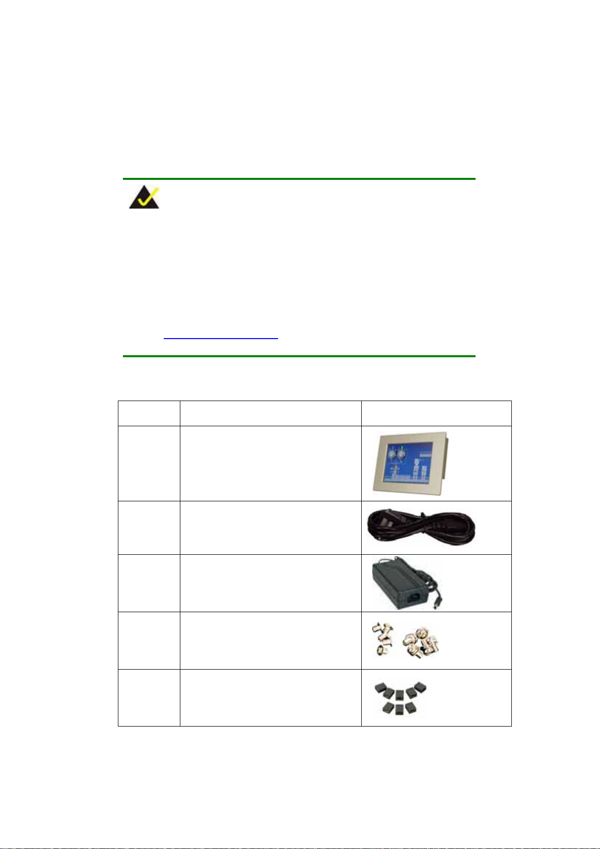
The EX-93821/EX-93823 is shipped with the following components:
Quantity Item and Part Number Image
.
Step 0:
1 EX-93821/EX-93823 flat panel PC
1 Power cord
1 45W power adapter
1 Screw kit
1 Jumper pack
Page 38
Page 39
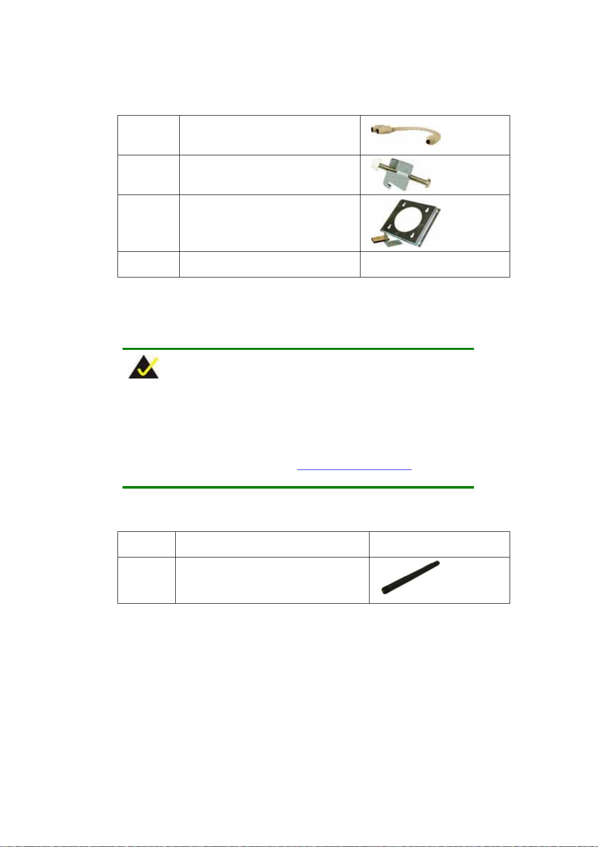
1 PS/2 keyboard/mouse Y cable
10 Panel mounting kit
1 Wall mounting kit
1 User manual and driver CD
Table 3-1: Package List Contents
3.4.2 Optional Items
NOTE:
The items listed in this section are optional items that must be ordered
separately. Please contact your EX-93821/EX-93823 vendor,
distributor or reseller for more information or, contact TOPSCCC
directly by sending an email to [email protected]
The following optional items are available for the EX-93821/EX-93823.
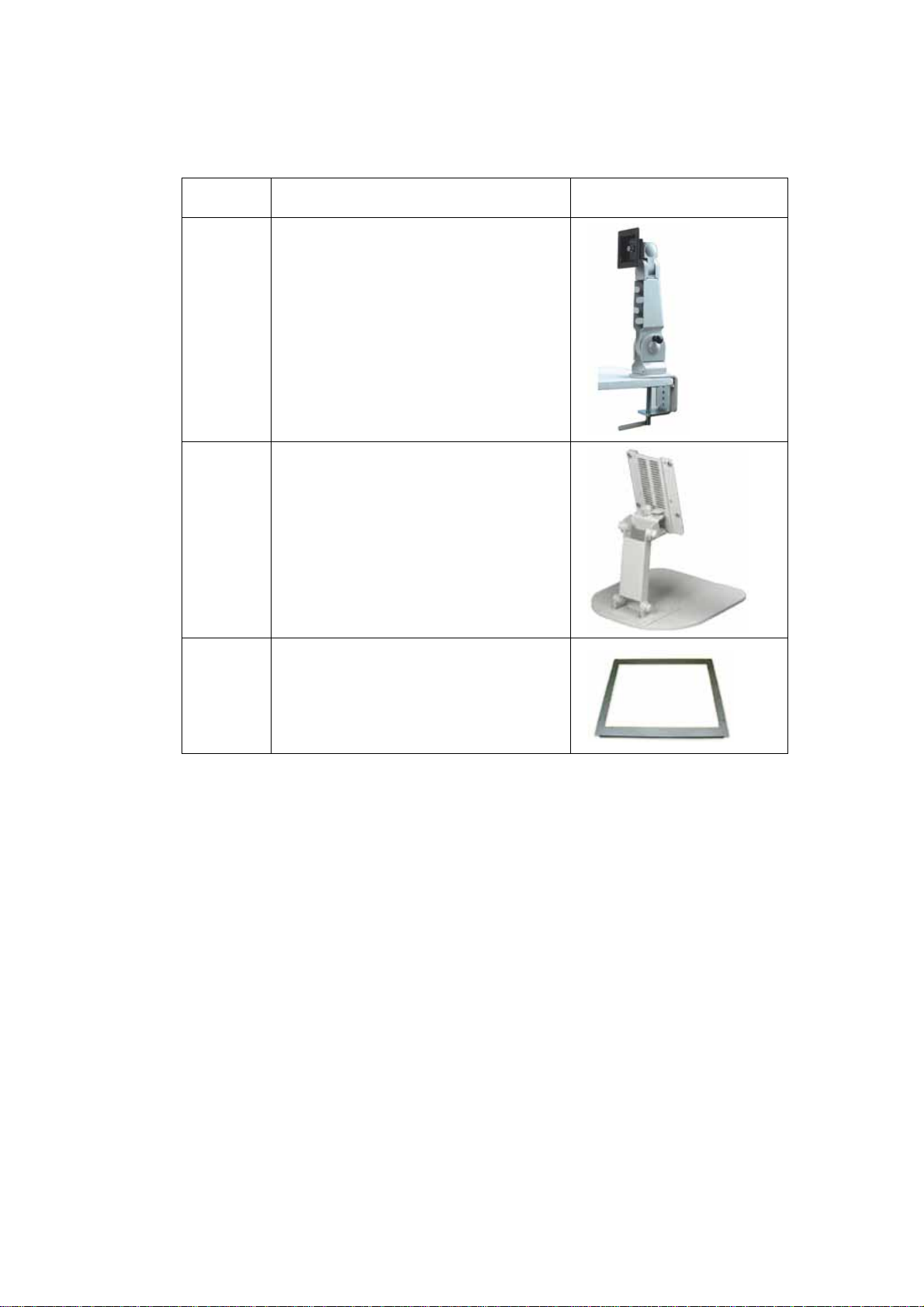
Quantity Item and Part Number Image
1 Wireless LAN antenna
(EXMB-LX-800W model only)
.
Page 39
Page 40
EX-93821/EX-93823 Flat Panel PC
Quantity Item and Part Number Image
1 LCD monitor arm kit
1 LCD monitor stand kit
1 Rack mounting kit
Table 3-2: Optional Items
3.5 CompactFlash® Card Installation
The EX-93821/EX-93823 embedded motherboard has one CF Type II slot on left side
panel. To install the CF card, follow the instructions below.
Step 1: Turn the panel PC over.
Step 2: Remove CF card slot cover by loosing the thumb screw.
Step 3: Insert the CF card into the slot. (Figure 3-1).
Page 40
Page 41
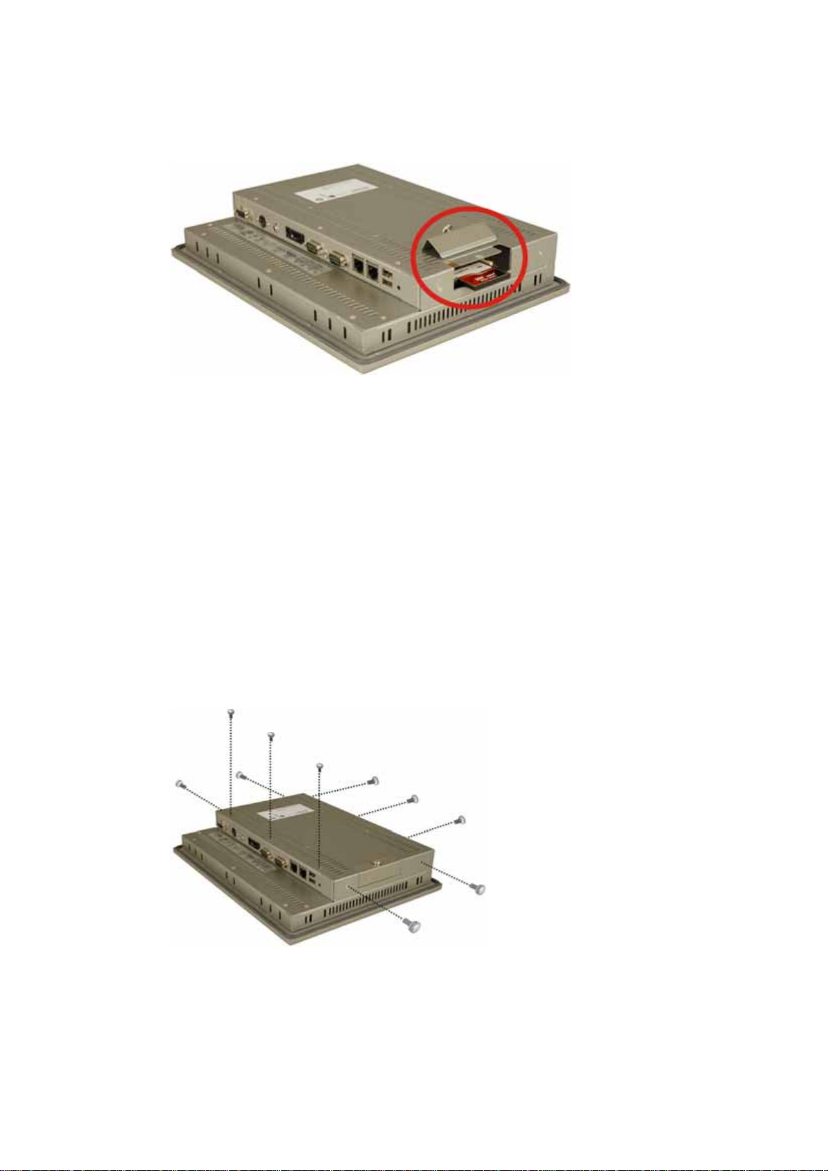
Figure 3-1: CF Card Installation
Step 4: Replace the CF card slot cover. Step 0:
3.6 Remove the Back Cover
Before the jumper settings can be configured and the HDD and DDR memory module can
be installed, the back cover of the flat panel PC must be removed. To remove the back
cover, please follow the steps below.
The back cover is secured to the chassis with ten retention screws, three on the top panel,
three on the rear panel, two on the right panel and two on the left panel (Figure 3-2).
Remove the ten retention screws and lift the cover off the EX-93821/EX-93823.
Figure 3-2: EX-93821 Back Cover Retention Screws
Page 41
Page 42
3.7 Jumper Settings
EX-93821/EX-93823 Flat Panel PC
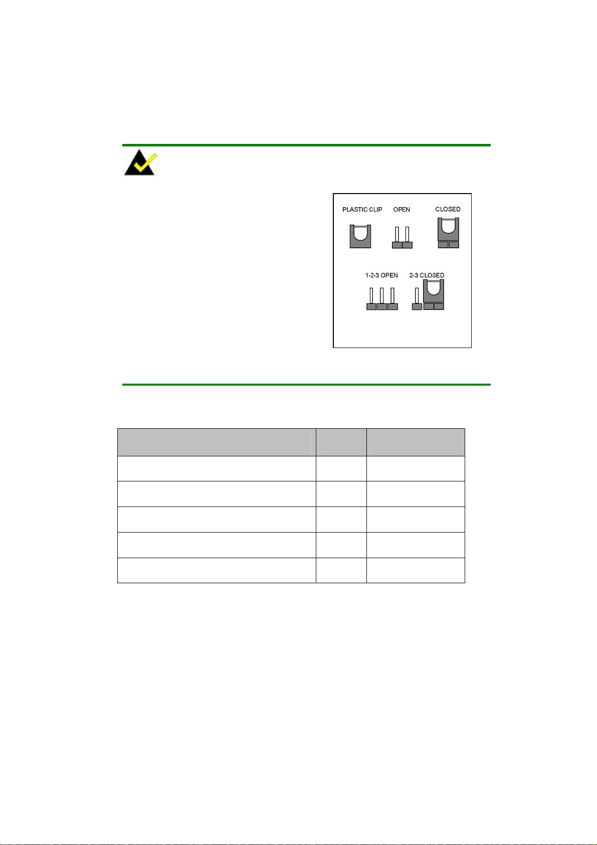
NOTE:
A jumper is a metal bridge that is used to
close an electrical circuit. It consists of
two metal pins and a small metal clip
(often protected by a plastic cover) that
slides over the pins to connect them.
To CLOSE/SHORT a jumper means
connecting the pins of the jumper with
the plastic clip and to OPEN a jumper
means removing the plastic clip from a
jumper.
The EXMB-LX-800 motherboard has several onboard jumpers (Table 3-3).
Description Label Type
Jumper
AT/ATX power select CN25 2-pin header
COM3 pin-9 signal select JP3 6-pin header
COM1 and COM2 pin-9 signal select JP4 10-pin header
COM2 port select (pin-12 signal select) JP5 12-pin header
COM2 port select (pin-3 signal select) JP6 3-pin header
T a bl e 3 - 3: Ju m p er s
3.7.1 AT/ATX Power Select
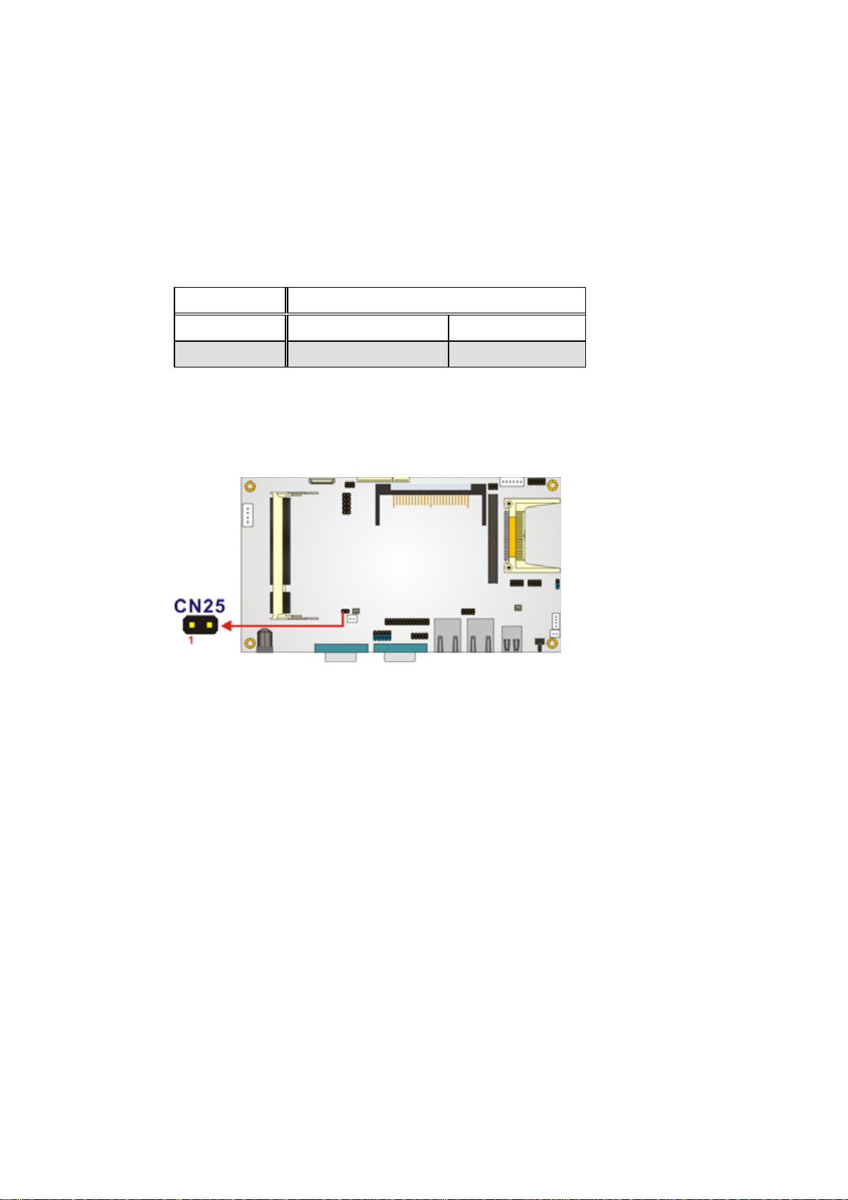
Jumper Label: CN25
Jumper Type:
Jumper Settings: See Table 3-4
Page 42
2-pin header
Page 43
Jumper Location:
The AT/ATX Power Select jumper specifies the systems power mode as AT or ATX. AT
See
Figure 3-3
Power Select jumper settings are shown in
JP3 Description
Short AT
Open ATX Default
Table 3-4: AT/ATX Power Sel ec t Jumper Settings
The location of the AT/ATX Power Select jumper is shown in Figure 3-3 below.
Table 3-4
.
Figure 3-3: AT/ATX Power Select Jumper Location
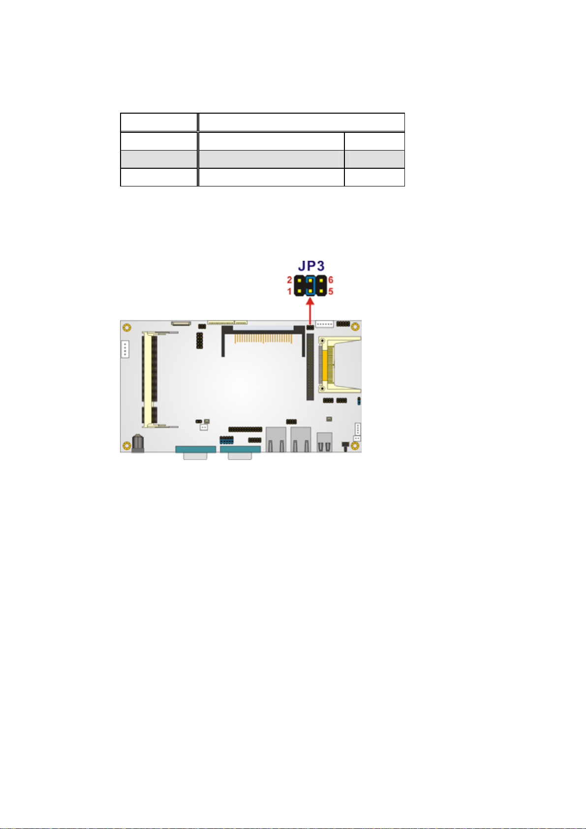
3.7.2 COM3 Pin-9 Signal Select Jumper Settings
Jumper Label: JP3
Jumper Type:
Jumper Settings:
Jumper Location: See Figure 3-4
The COM3 pin-9 signal can be selected as 12V, 5V or Ring.
6-pin header
See
Table 3-5
Page 43
Page 44
EX-93821/EX-93823 Flat Panel PC
JP3 Description
Short 1-2 COM3 pin-9 is 12V out put
Short 3-4 COM3 pin-9 is RI input Default
Short 5-6 COM3 pin-9 is 5V output
Table 3-5: COM3 Pin-9 Signal Select Jumper Settings
The location of the COM3 Pin-9 Signal Select jumper is shown in Figure 3-4 below.
Figure 3-4: COM3 Pin-9 Signal Select Jumper Location
3.7.3 COM1 and COM2 Pin-9 Signal Select Jumper Settings
Jumper Label: JP4
2-pin header
See
Table 3-6
Page 44
Jumper Type:
Jumper Settings:
Jumper Location: See Figure 3-5
The COM1 and COM2 pin-9 signal can be selected as 12V, 5V or Ring.
Page 45
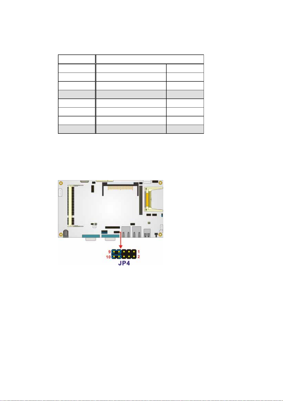
JP4 Description
Short 1, 3 COM1 pin-9 is 12V output
Short 3, 5 COM1 pin-9 is 5V output
Short 5, 7 COM1 pin-9 is 5V output
Short 7, 9 COM1 pin-9 is RI input Default
Short 2, 4 COM2 pin-9 is 12V output
Short 4, 6 COM2 pin-9 is 5V output
Short 6, 8 COM2 pin-9 is 5V output
Short 8, 10 COM2 pin-9 is RI input Default
Table 3-6: COM1 and COM2 Pin-9 Signal Select Jumper Settings
The location of the COM1 and COM2 Pin-9 Signal Select jumper is shown in Figure 3-5
below.
Figure 3-5: COM1 and COM2 Pin-9 Signal Select Jumper Location
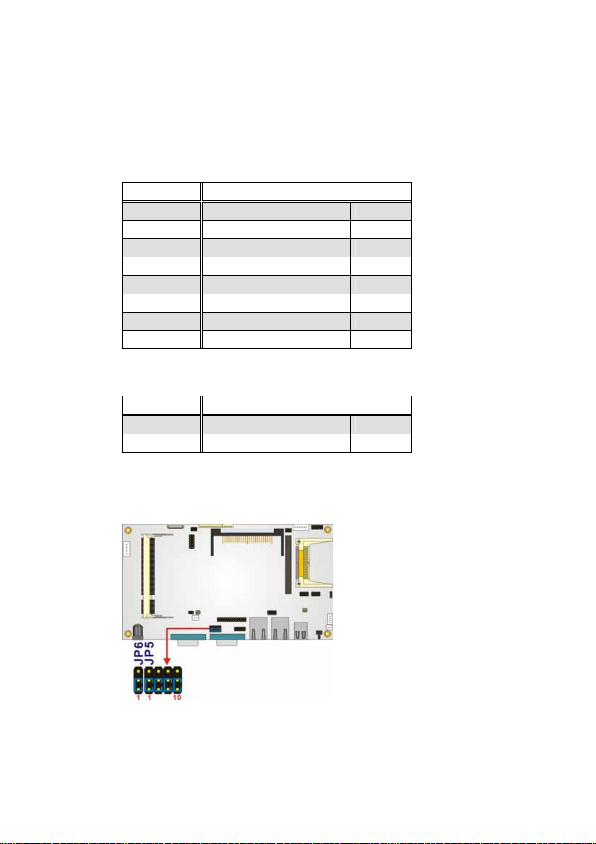
3.7.4 COM2 Select Jumper Settings
Jumper Label: JP5
Jumper Type:
12-pin header, 3-pin header
Jumper Settings: See Table 3-7 and Table 3-8
and
JP6
Page 45
Page 46
EX-93821/EX-93823 Flat Panel PC
Jumper Location:
See
Figure 3-6
The COM2 serial port can be set as RS-422/485 via JP5 and JP6.
JP5 Description
Short 1-2 DCD2 (RS-232) Default
Short 2-3 TX2-(RS-422/485)
Short 4-5 RXD2(RS-232) Default
Short 5-6 TX+(RS-422/485)
Short 7-8 DSR2(RS-232) Default
Short 8-9 RX-(RS-422/485)
Short 10-11 RTS2(RS-232) Default
Short 11-12 RX+(RS-422/485)
Table 3-7: COM2 Select Jumper Settings (JP5)
JP6 Description
Short 1-2 RS-232 Default
Short 2-3 RS-422/485
Table 3-8: COM2 Select Jumper Settings (JP6)
The location of the COM2 Select jumper is shown in Figure 3-6 below.
Figure 3-6: COM2 Select Jumper Location
Page 46
Page 47
3.8 HDD Installation
To install the HDD into the EX-93821/EX-93823, please follow the steps below:
Step 1: Remove the back cover. See Section 3.6 above.
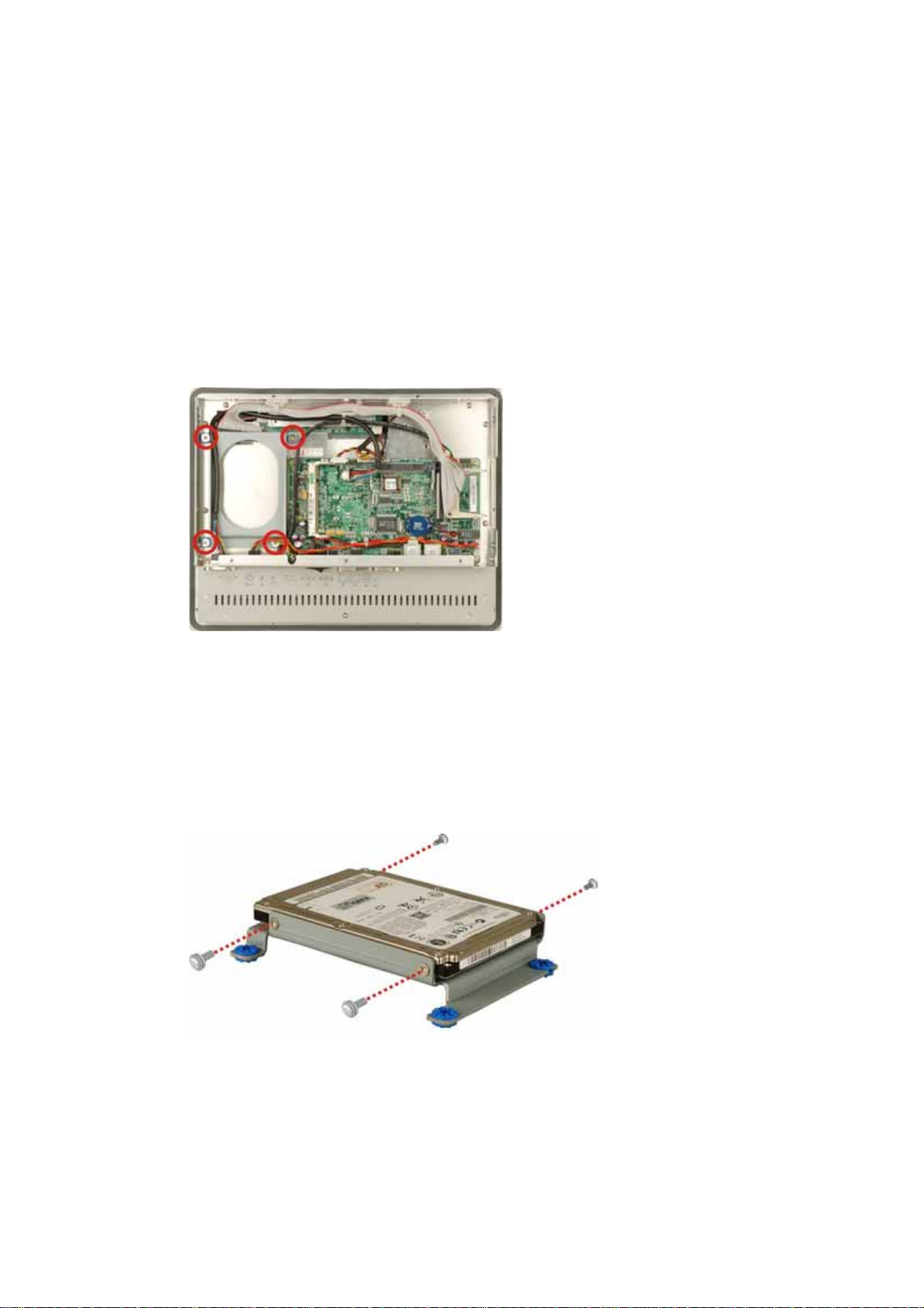
Step 2:
The HDD bracket is attached to the platform by four retention screws. Remove
the four retention screws from the platform (
Figure 3-7
).
Figure 3-7: HDD Bracket Retention Screws
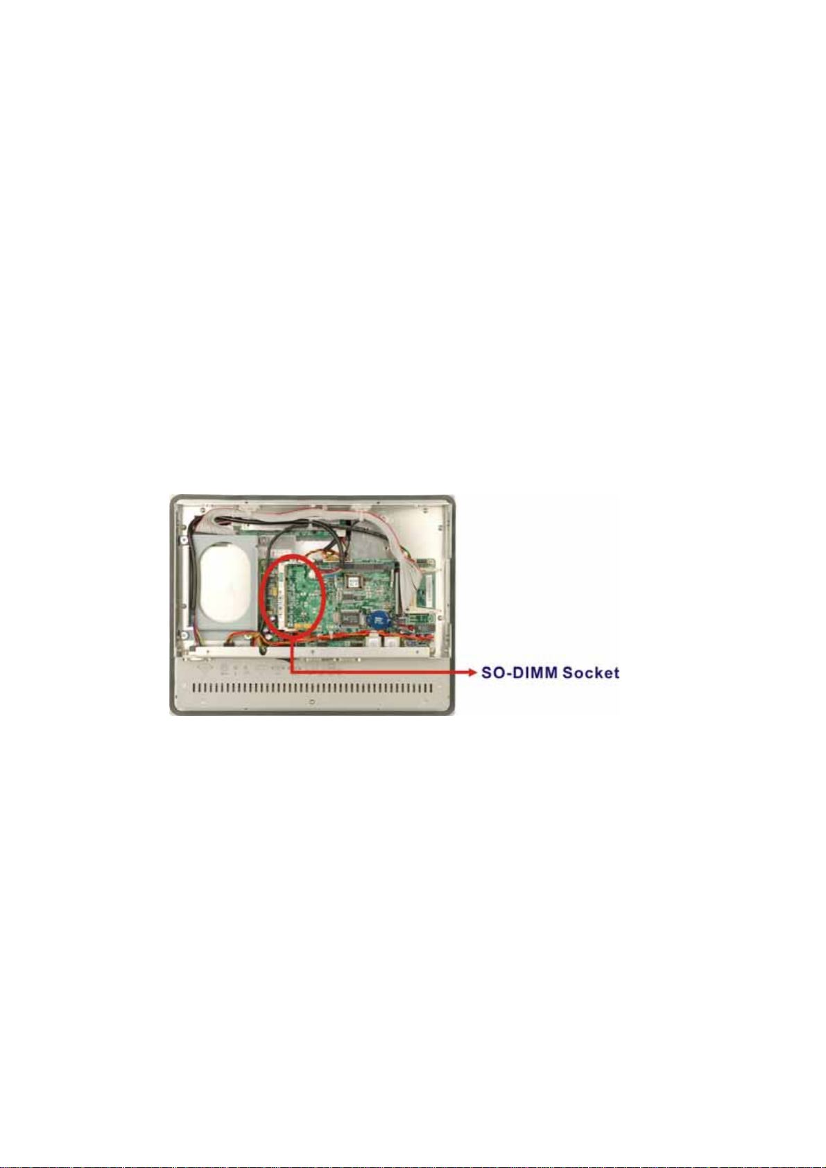
Step 3: Attach the HDD brackets to the HDD. To do this, align the four retention screw
holes in the two sides of the HDD bracket with the retention screw holes on the
sides of the HDD. Insert four retention screws into the HDD bracket (Figure
).
3-8
Figure 3-8: EX-93821/EX-93823 HDD Bracket Retention Screws
Step 4: Connect the IDE cable from the motherboard to the rear of HDD.
Page 47
Page 48
EX-93821/EX-93823 Flat Panel PC
Step 5:
Install the HDD into the EX-93821/EX-93823 by aligning the retention screw
holes in the base of the HDD brackets with the retention screw holes on the
platform. Insert the four retention screws. Step 0:
3.9 Memory Module Installation
The flat panel PC embedded motherboard has one 200-pin SO-DIMM socket. To install
the SO-DIMM module, follow the instructions below.
Step 1: Remove the back cover. See Section 3.6 above.
Step 2: Locate the SO-DIMM socket on the motherboard of the flat panel PC.
Page 48
Figure 3-9: EX-93821/EX-93823 SO-DIMM Socket Location
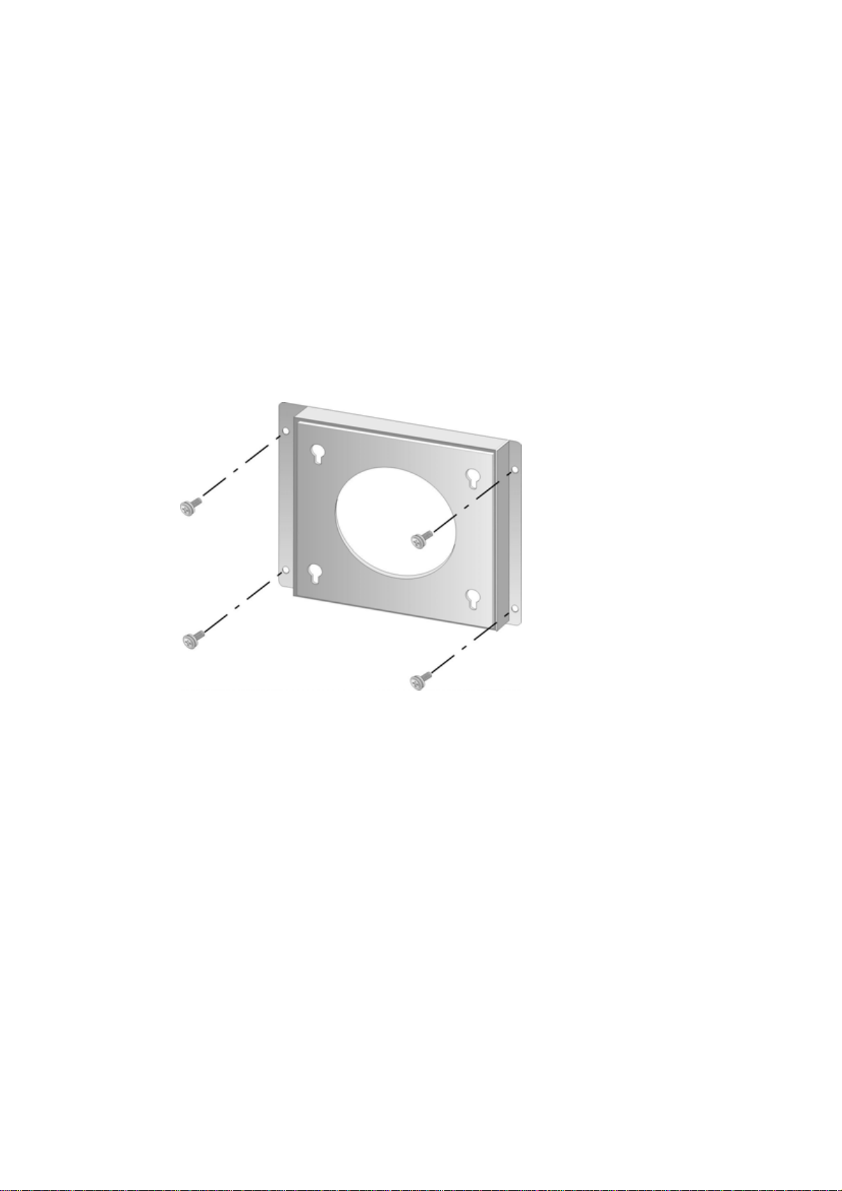
Step 3: Push the SO-DIMM chip into the socket at an angle. (See Figure 3-10)
Step 4: Gently pull the arms of the SO-DIMM socket out and push the rear of the
SO-DIMM module down. (See Figure 3-10)
Step 5:
Release the arms on the SO-DIMM socket. They clip into place and secure the
SO-DIMM module in the socket.
Step 0:
Page 49
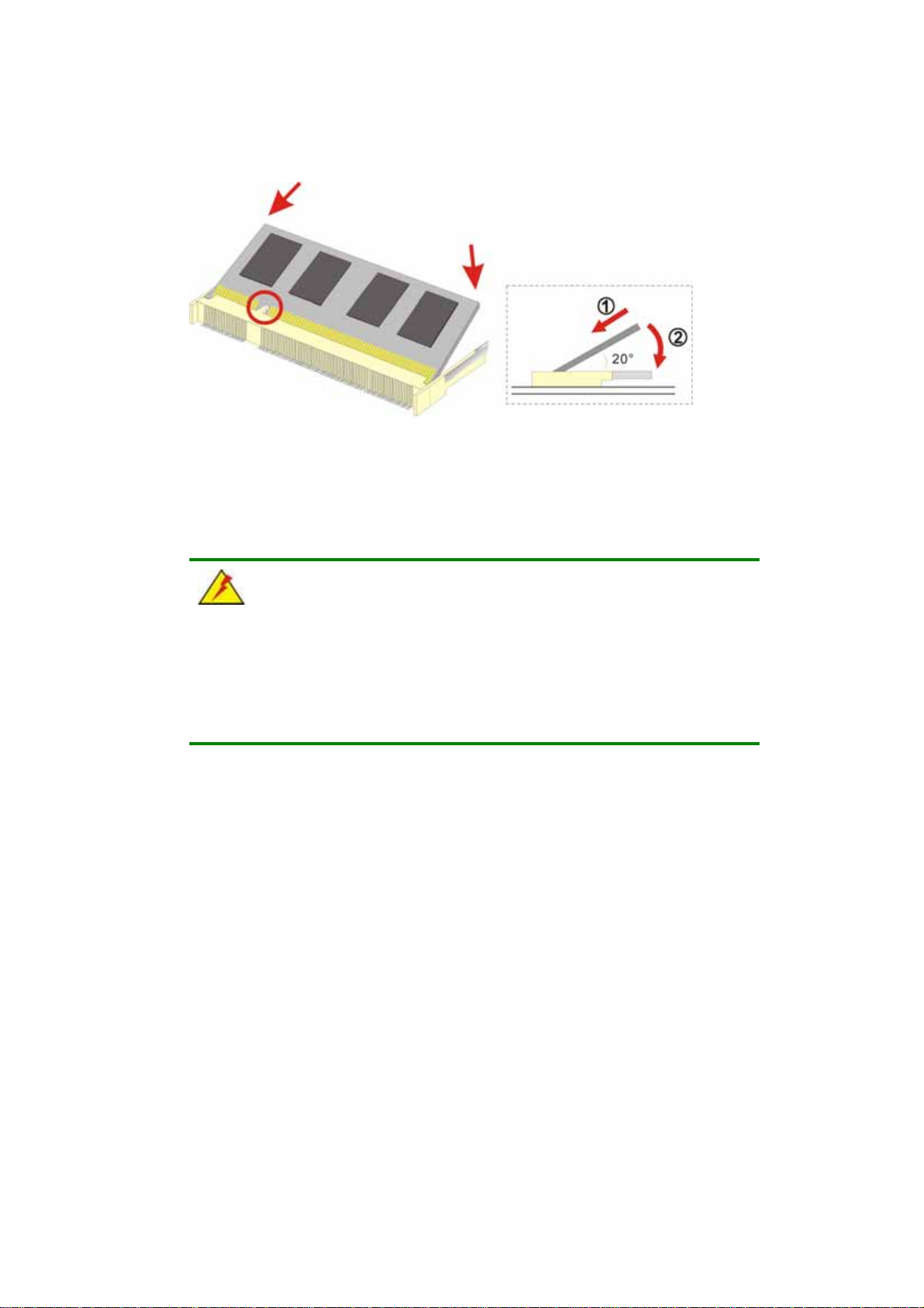
Figure 3-10: SO-DIMM Module Installation
3.10 Mounting the System
WARNING!
When mounting the flat panel PC onto an arm, onto the wall or onto a
panel, it is better to have more than one person to help with the installation
to make sure the panel PC does not fall down and get damaged.
The four methods of mounting the EX-93821/EX-93823 are listed below.
Wall mounting
Panel mounting
Rack mounting
The four mounting methods are described below.
3.10.1 Wall Mounting
To mount the flat panel PC onto the wall, please follow the steps below.
Step 1: Select the location on the wall for the wall-mounting bracket.
Arm mounting
Page 49
Page 50
EX-93821/EX-93823 Flat Panel PC
Step 2:
Step 3: Drill four pilot holes at the marked locations on the wall for the bracket retention
Step 4: Align the wall-mounting bracket screw holes with the pilot holes.
Step 5:
Carefully mark the locations of the four bracket screw holes on the wall.
screws.
Secure the mounting-bracket to the wall by inserting the retention screws into
the four pilot holes and tightening them (Figure 3-11).
Page 50
Figure 3-11: Wall-mounting Bracket
Step 6: Insert the four monitor mounting screws provided in the wall mounting kit into the
four screw holes on the real panel of the monitor and tighten until the screw
shank is secured against the rear panel (
Step 1: Align the mounting screws on the monitor rear panel with the mounting holes on
the bracket.
Step 2: Carefully insert the screws through the holes and gently pull the monitor
downwards until the monitor rests securely in the slotted holes (Figure 3-12).
Ensure that all four of the mounting screws fit snuggly into their respective
Figure 3-12
).
Page 51
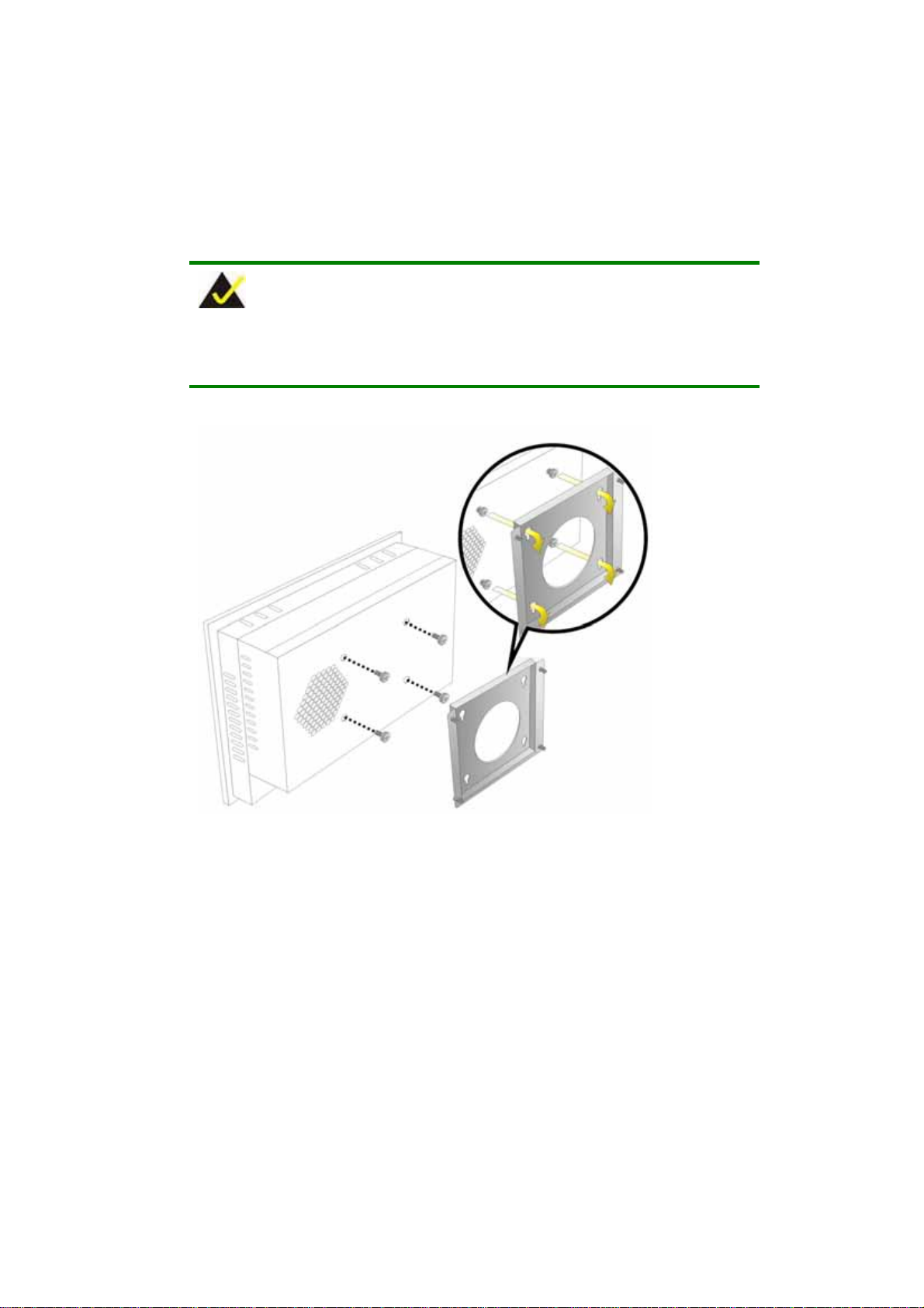
slotted holes.
NOTE:
In the diagram below the bracket is already installed on the wall.
Figure 3-12: Mount the Chassis
Step 3: Secure the panel PC with the wall-mounting kit. To do this, stick the protective
cushion to the wall-mounting kit first. Then, put the wall-mounting kit on the top
panel of the panel PC. Carefully mark the location of the wall-mounting kit screw
holes on the wall. Drill a pilot hole at the marked location on the wall. Secure the
wall-mounting kit to the wall by inserting a retention screw into the pilot hole on
the wall (Figure 3-13). This step is to avoid the panel PC being pushed apart
Page 51
Page 52
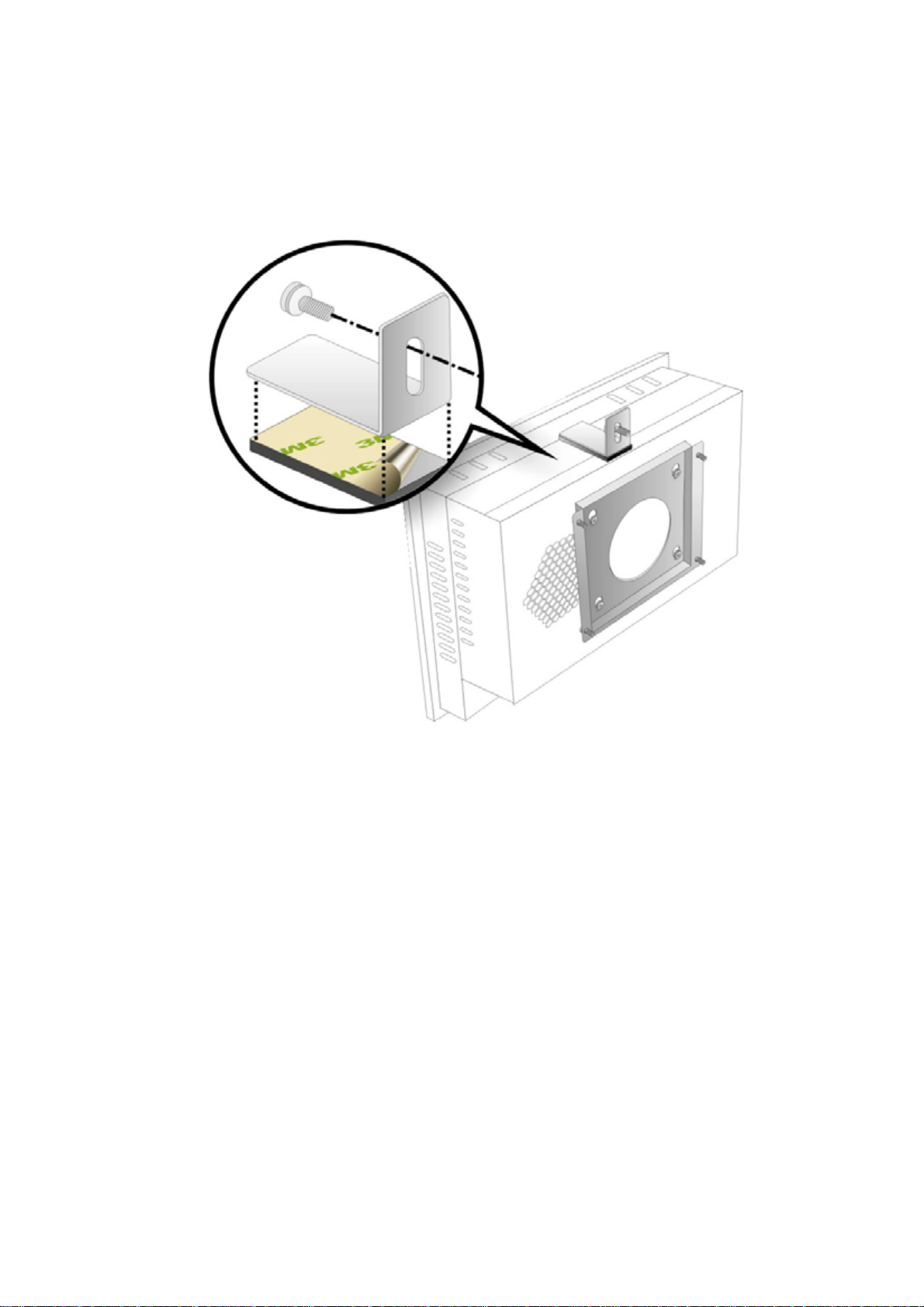
EX-93821/EX-93823 Flat Panel PC
from the wall-mounting bracket accidentally.
Step 0:
Figure 3-13: Secure the Chassis
3.10.2 Panel Mounting
To mount the EX-93821/EX-93823 flat panel PC into a panel, please follow the steps
below.
Step 1: Select the position on the panel to mount the flat panel PC.
Step 2: Cut out a section from the panel that corresponds to the rear panel dimensions
of the flat panel PC. Take care that the panel section that is cut out is smaller
than the overall size of the metal frame that surrounds the flat panel PC but just
large enough for the rear panel of the flat panel PC to fit through (Figure 3-14
and Figure 3-15).
Page 52
Page 53
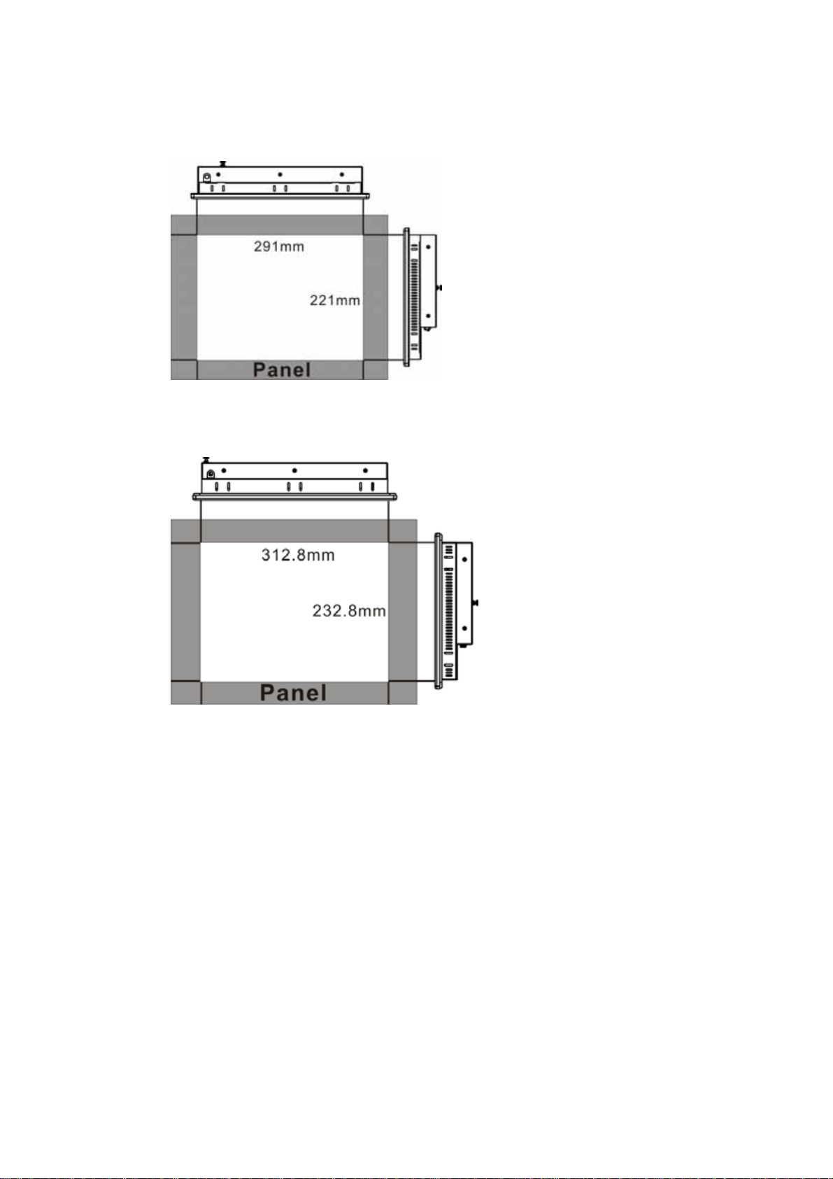
Figure 3-14: EX-93821 Panel Opening
Figure 3-15: EX-93823 Panel Opening
Step 3: Slide the flat panel PC through the hole until the aluminum frame is flush against
the panel.
Step 4: Insert the panel mounting clamps into the pre-formed holes along the edges of
the chassis, behind the aluminum frame. There are a total of 10 panel mounting
clamps.
Step 5: Tighten the screws that pass through the panel mounting clamps until the plastic
caps at the front of all the screws are firmly secured to the panel (Figure 3-16).
Step 0:
Page 53
Page 54
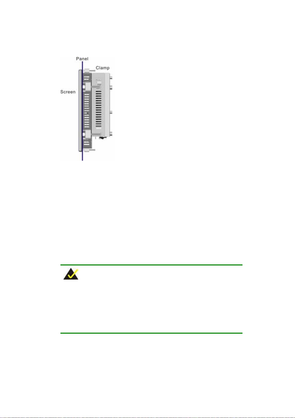
EX-93821/EX-93823 Flat Panel PC
Figure 3-16: Tighten the Panel Mounting Clamp Screws
3.10.3 Arm Mounting
The EX-93821/EX-93823 is VESA (Video Electronics Standards Association) compliant
and can be mounted on an arm with a 100mm interface pad. To mount the
EX-93821//EX-93823 on an arm, please follow the steps below.
Step 1: The arm is a separately purchased item. Please correctly mount the arm onto
the surface it uses as a base. To do this, refer to the installation documentation
that came with the mounting arm.
NOTE:
When purchasing the arm please ensure that it is VESA compliant and that
the arm has a 100mm interface pad. If the mounting arm is not VESA
compliant it cannot be used to support the EX-93821/EX-93823 flat panel
PC.
Page 54
Step 2: Once the mounting arm has been firmly attached to the surface, lift the flat panel
PC onto the interface pad of the mounting arm.
Page 55
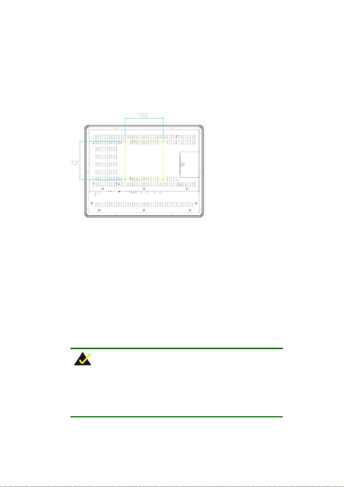
Step 3:
Figure 3-17: Arm Mounting Retention Screw Holes
Align the retention screw holes on the mounting arm interface with those in the
flat panel PC. The flat panel PC arm mount retention screw holes are shown in
Figure 3-17.
Step 4:
Secure the flat panel PC to the interface pad by inserting four retention screws
through the bottom of the mounting arm interface pad and into the flat panel PC.
Step 0:
3.10.4 Cabinet and Rack Installation
The EX-93821/EX-93823 flat panel PC can be installed into a cabinet or rack. The
installation procedures are similar to the panel mounting installation. To do this, please
follow the steps below:
NOTE:
When purchasing the cabinet/rack installation bracket, make sure it is
compatible with both the EX-93821/EX-93823 flat panel PC and the
rack/cabinet into which the EX-93821/EX-93823 is installed.
Page 55
Page 56
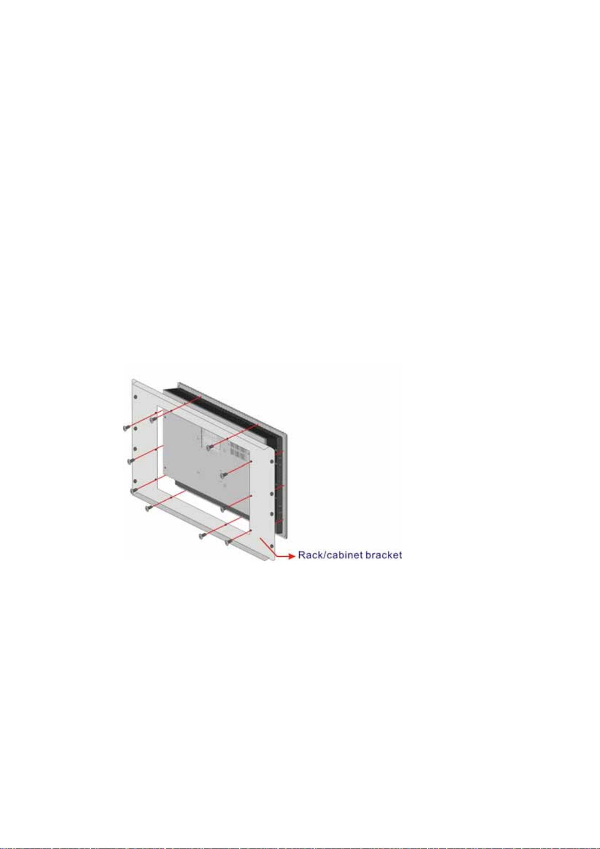
EX-93821/EX-93823 Flat Panel PC
Step 1: The back of the aluminum frame surrounding the EX-93821/EX-93823 TFT LCD
screen has 10 retention screw holes for a cabinet/rack installation bracket.
Step 2: Slide the rear chassis of the EX-93821/EX-93823 flat panel PC through the
rack/cabinet bracket until the rear side of the LCD screen frame is flush against
the front of the bracket.
Step 3: Make sure the retention screw holes at the rear of the LCD screen are aligned
with the retention screw holes in the rack/cabinet bracket.
Step 4: Secure the rack/cabinet bracket to the EX-93821/EX-93823 flat panel PC by
inserting the retention screws (Figure 3-18).
Page 56
Figure 3-18: Secure the EX-93821/EX-93823 Rack/Cabinet Bracket
Step 5: Slide the EX-93821/EX-93823 flat panel PC with the attached rack/cabinet
bracket into a rack or cabinet (Figure 3-19).
Page 57
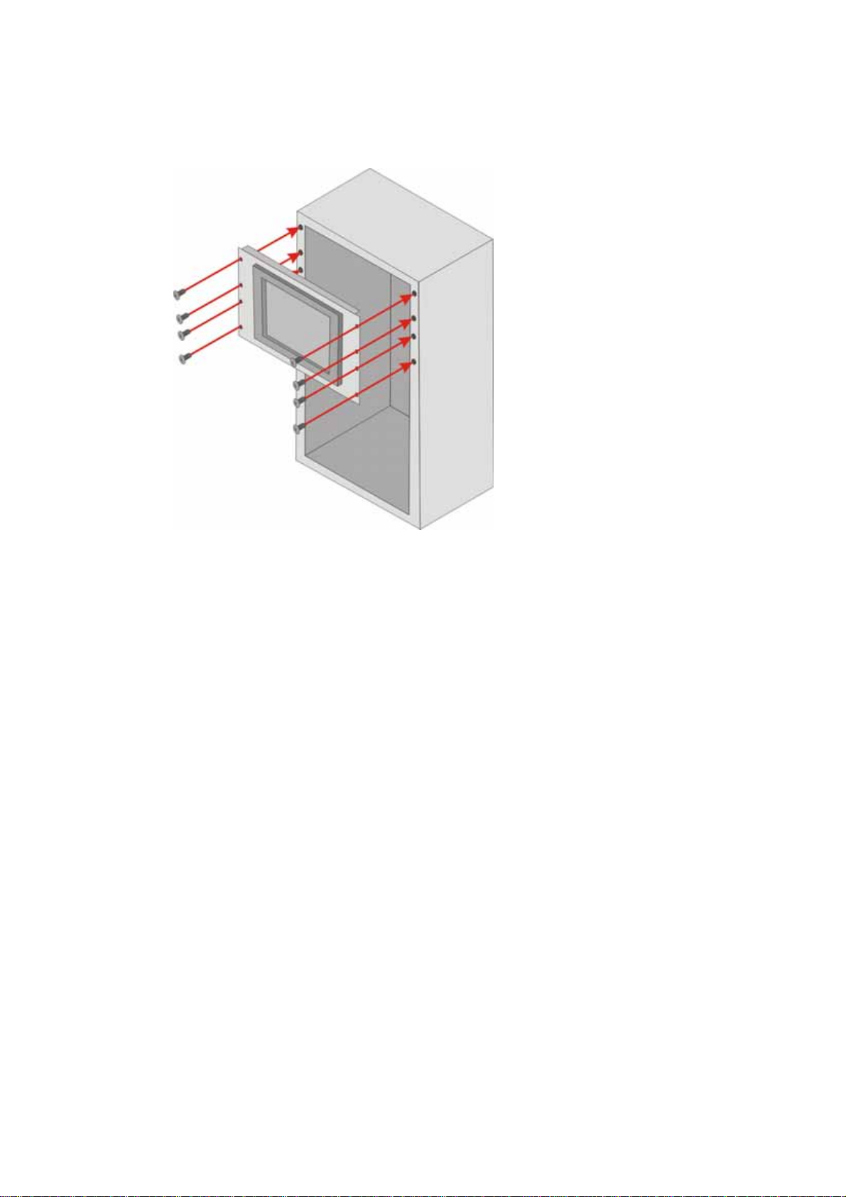
Figure 3-19: Install into a Rack/Cabinet
Step 6: Once the EX-93821/EX-93823 flat panel PC with the attached rack/cabinet
bracket has been properly inserted into the rack or cabinet, secure the front of
the rack/cabinet bracket to the front of the rack or cabinet (Figure 3-19).Step 0:
3.11 Rear Panel Connectors
3.11.1 LCD Panel Connection
To connect the EX-93821/EX-93823 flat panel PC to a second monitor, a conventional
CRT VGA monitor connector is located on the bottom panel. This panel is a 15-pin, female
D-SUB connector.
3.11.2 Ethernet Connection
The two rear panel RJ-45 connectors can be connected to an external LAN and provide
Internet connectivity to the flat panel PC.
Page 57
Page 58

EX-93821/EX-93823 Flat Panel PC
3.11.3 USB Connection
The rear panel USB connectors provide easier and quicker access to external USB
devices. The rear panel USB connector is a standard connector and can easily be
connected to other USB devices.
3.11.4 Keyboard and Mouse Connection
One PS/2 connector on the bottom panel facilitates the connection of a mouse and a
keyboard. To connect either device, plug the PS/2 connector at the end of the keyboard or
mouse cable into the corresponding PS/2 connector on the external peripheral interface
panel.
3.12 System Maintenance
If the components of the EX-93821/EX-93823 fail they must be replaced. Please contact
the system reseller or vendor to purchase the replacement parts.
NOTE:
A user cannot replace a motherboard. If the motherboard fails it must be
shipped back to TOPSCCC to be replaced. Please contact the system
vendor, reseller or an TOPSCCC sales person directly.
Page 58
Page 59

Chapter
4
4 Gasket Replacement
Page 59
Page 60
EX-93821/EX-93823 Flat Panel PC
4.1 Gasket Replacement
A gasket used for a long time may gradually lose its ability to protect the monitor from
fluids and vapors; scratches or dirt may also accumulate. It is recommended that the
gasket be replaced yearly.
NOTE:
If the monitor is mounted vertically, first remove it and place it on a flat, level
surface with the display screen facing down before changing the gasket.
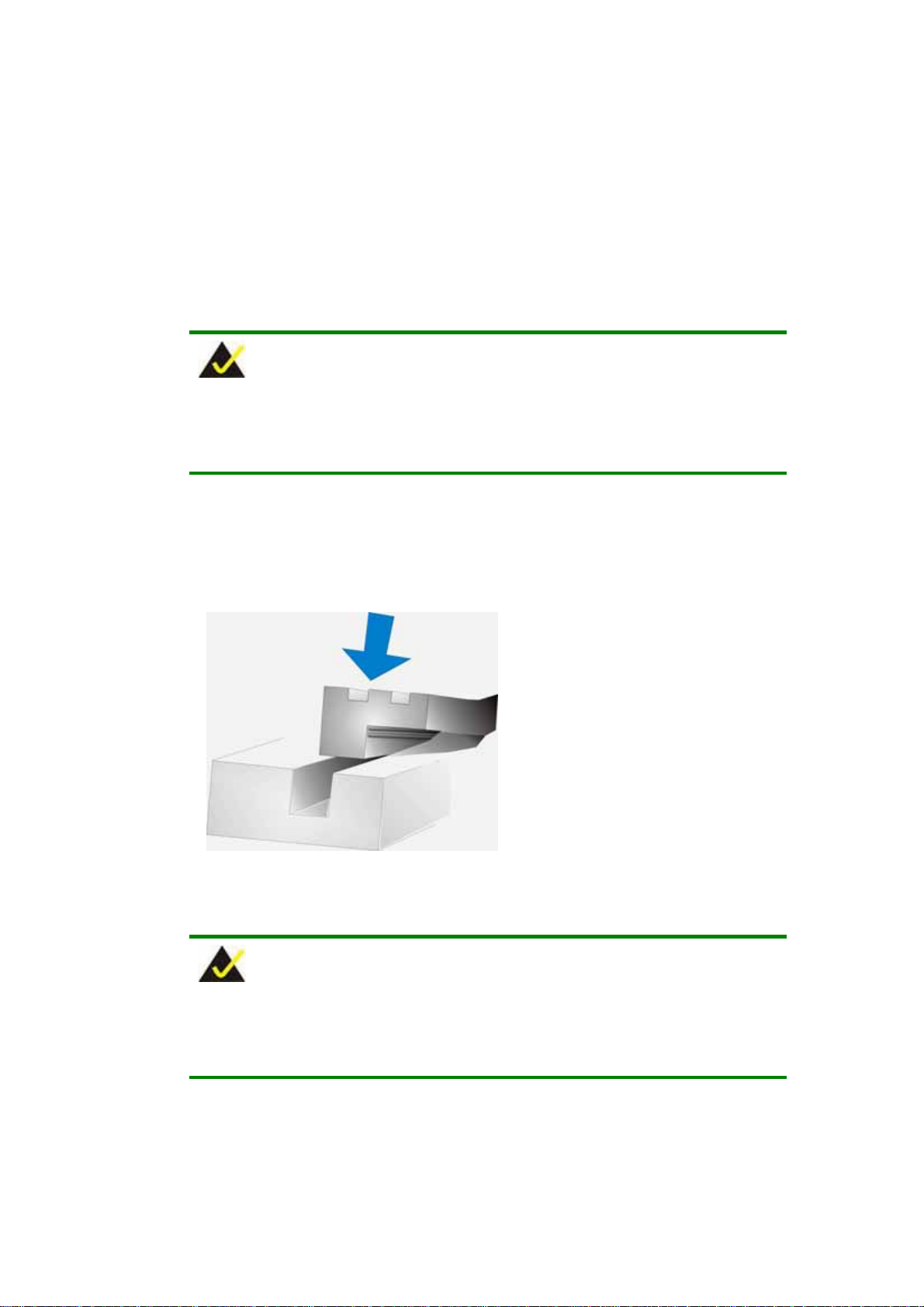
Step 1: Remove the old gasket from the sides of the monitor.
Step 2: Attach the new gasket to the monitor. Make sure the gasket fits precisely into the
groove along the edges of the monitor’s front panel (Figure 4-1).
Figure 4-1: Gasket Replacement
NOTE:
Compliance with the IP 65 standard depends on correct installation of the
Page 60
gasket. Be sure to check that the gasket is properly installed after changing it.
Page 61

Chapter
5
5 AMI BIOS Setup
Page 61
Page 62
5.1 Introduction
A licensed copy of Phoenix Award BIOS is preprogrammed into the ROM BIOS. The BIOS
setup program allows users to modify the basic system configuration. This chapter
describes how to access the BIOS setup program and the configuration options that may
be changed.
5.1.1 Starting Setup
The Phoenix Award BIOS is activated when the computer is turned on. The setup program
can be activated in one of two ways.
EX-93821/EX-93823 Flat Panel PC
1. Press the D
2. Press the D
appears on the screen.
If the message disappears, restart the computer and try again.
key as soon as the system is turned on or
ELETE
ELETE key when the “Press Del to enter SETUP” message
5.1.2 Using Setup
Use the arrow keys to highlight items, press E
P
AGEDOWN keys to change entries, press F1 for help and press ESC to quit. Navigation
keys are shown below.
Key Function
Up arrow Move to the item above
Down arrow Move to the item below
Left arrow Move to the item on the left hand side
Right arrow Move to the item on the right hand side
+/Page up Increase the numeric value or make changes
to select, use the P
NTER
AGEUP
and
Page 62
-/Page down Decrease the numeric value or make changes
Esc Main Menu – Quit and do not save changes into CMOS
Status Page Setup Menu and Option Page Setup Menu --
Exit current page and return to Main Menu
F1 General help, only for Status Page Setup Menu and Option
Page Setup Menu
Page 63
F2 Item help
F5 Previous values for the page menu items
F6 Fail-safe defaults for the current page menu items
F7 Optimized defaults for the current page menu items
F9 Menu in BIOS
F10 Save changes and Exit BIOS
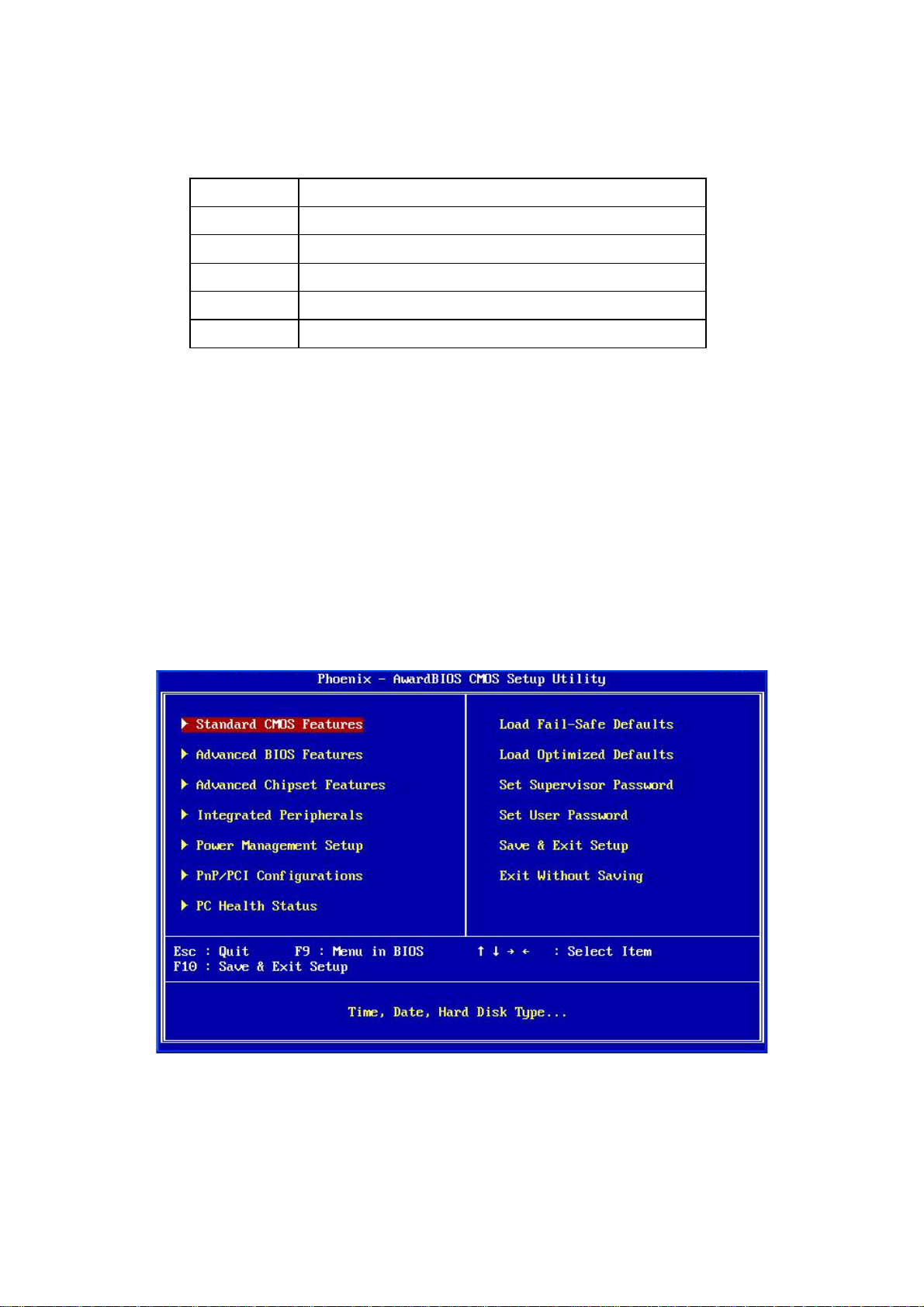
Table 5-1: BIOS Navigation Keys
5.1.3 Getting Help
When F1 is pressed a small help window describing the appropriate keys to use and the
possible selections for the highlighted item appears. To exit the Help Window press E
the F1 key again.
5.1.4 Main BIOS Menu
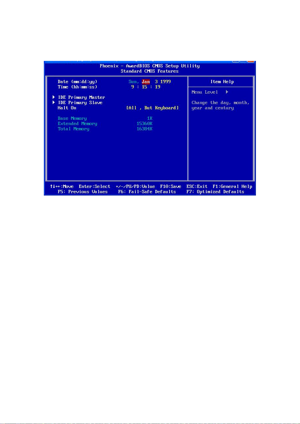
Once the BIOS opens, the main menu (
BIOS Menu 1
) appears.
SC or
BIOS Menu 1: Award BIOS CMOS Setup Utility
Page 63
Page 64

EX-93821/EX-93823 Flat Panel PC
NOTE:
The following sections will completely describe the menus listed below and
the configuration options available to users.
The following menu options are seen in BIOS Menu 1.
Standard CMOS Features
Advanced BIOS Features: Changes the advanced system settings.
Advanced Chipset Features : Changes the chipset configuration features.
Integrated Peripherals: Changes the settings for integrated peripherals.
Power Management Setup
PnP/PCI Configurations: Changes the advanced PCI/PnP settings.
PC Health Status: Monitors essential system parameters.
: Changes the basic system configuration.
: Configures power saving options.
The following user configurable options are also available in BIOS Menu 1:
Load Fail-Safe Defaults
Use the Load Fail-Safe Defaults option to load failsafe default values for each BIOS
parameter in the setup menus. Press F6 for this operation on any page.
Load Optimized Defaults
Use the
Load Optimized Defaults
option to load optimal default values for each BIOS
parameter in the setup menus. Press
Set Supervisor Password
Use the Set Supervisor Password option to set the supervisor password. By default, no
supervisor password is set. To install a supervisor password, select this field and enter the
password. After this option is selected, a red dialogue box appears with “Enter
Password: ”. Type the password and press E
“Confirm Password: ” dialogue box and press E
Page 64
for this operation on any page.
F7
NTER. Retype the original password into the
NTER. To disable the password, simply
Page 65

press ENTER in the “Enter Password: ” dialogue box, then press any key in the
“Password Disabled !!!” dialogue box.
Set User Password
Use the Set User Password option to set the user password. By default no user
password is set. To install a user password, select this field and enter the password. After
this option is selected, a red dialogue box appears with “
password and press
dialogue box and press E
Password: ” dialogue box, then press any key in the “Password Disabled !!!” dialogue
box.
Save & Exit Setup
Use the Save & Exit Setup option to save any configuration changes made and exit the
BIOS menus.
Exit Without Saving
Use the Exit Without Saving option to exit the BIOS menus without saving any
configuration changes.
. Retype the original password into the “
E
NTER
. To disable the password, simply press E
NTER
5.2 Standard CMOS Features
Enter Password:
Confirm Password:
NTER
”. Type the
”
in the “Enter
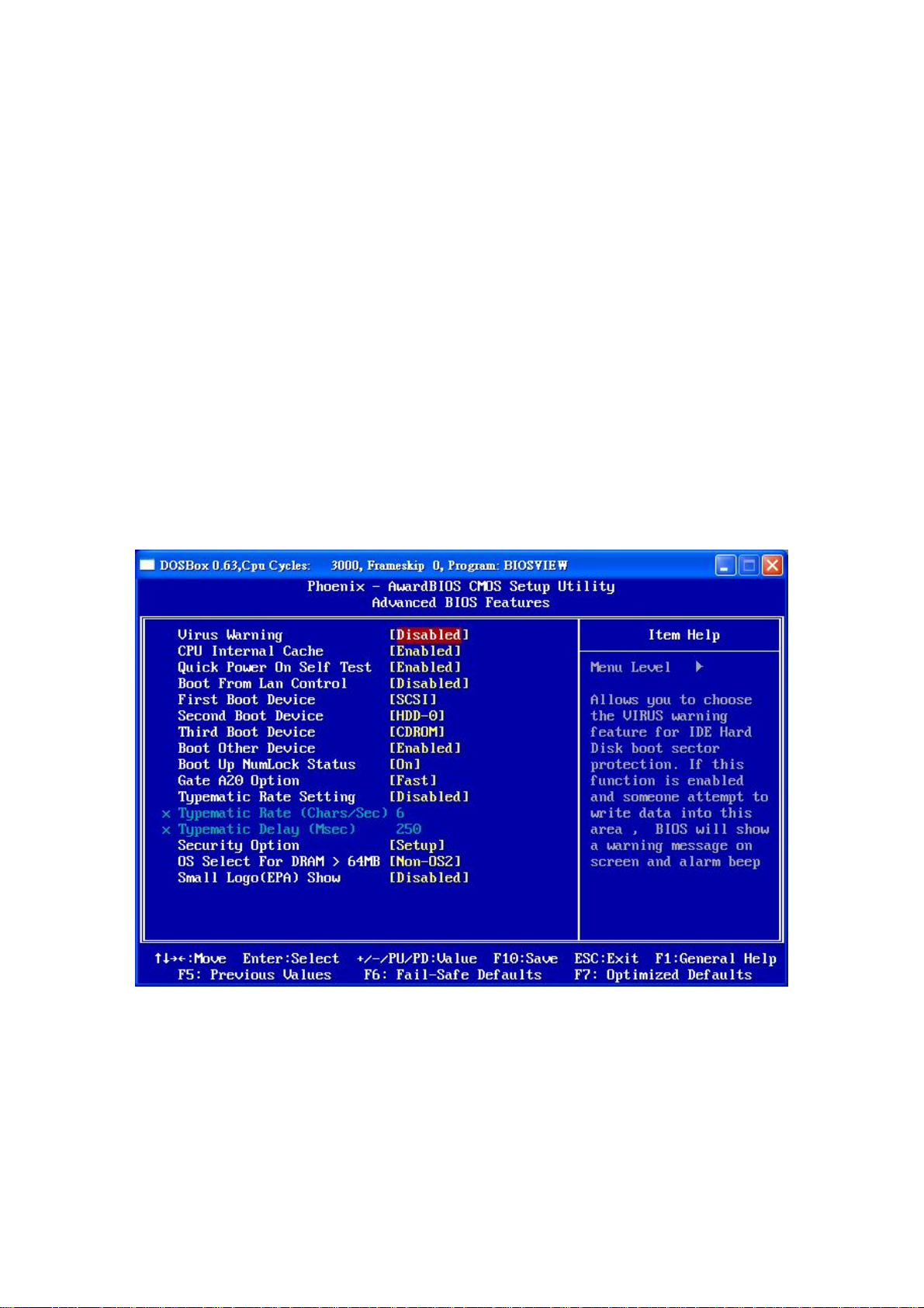
Use the Standard CMOS Features BIOS menu (
configuration options.
BIOS Menu 2
) to set basic BIOS
Page 65
Page 66
EX-93821/EX-93823 Flat Panel PC
BIOS Menu 2: Standard CMO S Features
Date [Day mm:dd:yyyy]
Use the Date option to set the system date.
Time [hh/mm/ss]
Use the Time option to set the system time.
IDE Master and IDE Slave
When entering setup, BIOS auto detects the presence of IDE devices. The Standard
CMOS Features menu shows the status of the auto detected IDE devices. The following
IDE devices are detected and shown in the Standard CMOS Features menu:
IDE Primary Master
IDE Primary Slave
Page 66
Page 67

IDE device configurations are changed or set in the IDE Configuration menu. If an IDE
device is detected, and one of the above listed two BIOS configuration options is selected,
the IDE configuration options shown in Section 5.2.1 appear.
Halt On [All, But Keyboard]
Use the Halt On option to specify what errors detected during the power up process stop
the system.
All Errors
No Errors
All, But Keyboard
Base Memory:
The Base Memory is NOT user configurable. The POST determines the amount of base
(or conventional) memory installed in the system. The value of the base memory is
typically 512K for systems with 512K memory installed, or 640K for systems with 640K or
more memory installed.
Extended Memory
Whenever BIOS detects a non-fatal error the
system is stopped and the user prompted.
The system boot is not stopped for any errors
that may be detected.
(Default) The system boot does not stop for a keyboard
error; it stops for all other errors.
The Extended Memory is NOT user configurable. The BIOS determines how much
extended memory is present during the POST. This is the amount of memory above 1MB
located in the memory address map of the CPU.
Total Memory
The Total Memory is NOT user configurable.
Page 67
Page 68

EX-93821/EX-93823 Flat Panel PC
5.2.1 IDE Primary Master/Slave
Use the IDE Primary Master/Slave menu to set or change the master/slave IDE
configurations.
IDE HDD Auto-Detection [Press Enter]
Use the IDE HDD Auto-Detection option to enable BIOS to automatically detect the IDE
settings. Select ID E HDD Auto- Detection and press E
the HDD type. Do not set this option manually.
IDE Primary Master [Auto]
Use the IDE Primary Master option to activate or deactivate the following drive channels:
Channel 0 Master
Channel 0 Slave
Channel 1 Master
Channel 1 Slave
None
Auto
NTER. BIOS automatically detects
If no drives are connected to the IDE channel select this
option. Once set, this IDE channel becomes
inaccessible and any drives attached to it are
undetected.
(Default) Setting this option allows the device to be automatically
Manual
Access Mode [Auto]
The Access Mode option can only be configured if the BIOS configuration option is set to
either Manual or Auto. Use the Access Mode option to determine the hard disk BIOS
Page 68
detected by the BIOS.
Selecting this option allows manual configuration of the
device on the IDE channel in BIOS.
Page 69

translation modes. Most systems now use hard drives with large capacities and therefore
either the LBA translation mode or auto mode should be selected.
CHS
LBA
Large
Auto
Capacity
The Capacity specification indicates the storage capacity of the HDD installed in the
system.
Select this mode if the HDD capacity is less than
504MB.
Select this mode if the HDD capacity is more than
8.4GB.
This mode is an extended ECHS mode and while it
supports HDDs larger than 504MB, it is not
recommended.
(Default) If you are unsure of what access mode to set, select this
option.
Cylinder
The Cylinder specification indicates how many cylinders (tracks) are on the HDD installed
in the system.
The Head specification indicates how many logical heads are on the HDD installed in the
system.
Precomp
The
Head
Precomp
specification indicates on what track the write precompensation begins.
Page 69
Page 70
EX-93821/EX-93823 Flat Panel PC
Landing Zone
The Landing Zone specification indicates where the disk head will park itself after the
system powers off.
Sector
The Sector specification indicates how many logical sectors the HDD has been divided
into.
5.3 Advanced BIOS Features
Use the
peripheral device configuration options.
Advanced BIOS Features
menu (
BIOS Menu 3
) to configure the CPU and
BIOS Menu 3: Advanced BIOS Features
Page 70
Page 71

Virus Warning [Disabled]
NOTE:
Many disk diagnostic programs can cause the above warning message to
appear when the program attempts to access the boot sector table. If you
are running such a program, it is recommended that the virus protection
function be disabled beforehand.
Use the
table of the HDD for any attempted modification. If a modification attempt is made, the
BIOS halts the system and an error message appears. If necessary, an anti-virus program
can then be run to locate and remove the virus before any damage is done.
CPU Internal Cache [Enabled]
Use the CPU Internal Cache option to enable or disable the internal CPU cache.
Virus Warning
Enabled
Disabled
Disabled
option to enable BIOS to monitor the boot sector and partition
Activates automatically when the system boots up
causing a warning message to appear when anything
attempts to access the boot sector or HDD partition table.
(Default) No warning message appears when there is an attempt
to access the boot sector or HDD partition table.
The internal CPU cache is disabled.
Enabled
Quick Power On Self Test [Enabled]
Use the Quick Power On Self Test option to speed up the POST after the computer is
turned on. If enabled, BIOS shortens or skips some POST check items.
(Default) The internal CPU cache is enabled.
Page 71
Page 72

EX-93821/EX-93823 Flat Panel PC
Disabled Normal POST occurs after the computer is turned on.
Enabled (Default) Quick POST occurs after the computer is turned on.
Boot From LAN Control [Disabled]
Use the
remote system.
Boot Device
Use the Boot Device options to select the order of the devices the system boots from.
There are three boot device configuration options:
BOOT From LAN Control
Disabled
Enabled
First Boot Device
Second Boot Device [Default: HDD-0]
Third Boot Device [Default: CDROM]
(Default) The system cannot be booted from a remote system
The system can be booted from a remote system
option to enable the system to be booted from a
through the LAN.
through the LAN.
[Default: SCSI]
Page 72
Using the default values, the system first looks for a SCSI drive to boot from. If it cannot
find a SCSI drive, it boots from a HDD. If both The SCSI drive and the HDD are
unavailable, the system boots from a CD-ROM.
Boot Device configuration options are:
LS120
HDD-0
SCSI
CDROM
HDD-1
USB-FDD
Page 73

USB-ZIP
USB-CDROM
USB-HDD
LAN
Disabled
Boot Other Device [Enabled]
Use the
third boot device if the first boot device is not found.
Boot Up Numlock Status [On]
Use the Boot Up Numlock Status option to specify the default state of the numeric
keypad.
Boot Other Device
Disabled
Enabled
Off
On
The system does not look for second and third boot
(Default) The system looks for second and third boot devices if the
The keys on the keypad are not activated.
(Default) Activates the keys on the keypad.
option to determine whether the system uses a second or
devices if the first one is not found.
first one is not found.
Gate A20 Option [Fast]
Use the Gate A20 Option to set if the keyboard controller or the chipset controls the Gate
A20 switching.
Normal
Fast
The keyboard controller does the switching.
(Default) The chipset does the switching.
Page 73
Page 74

EX-93821/EX-93823 Flat Panel PC
Typematic Rate Setting [Disabled]
Use the Typematic Rate Setting configuration option to specify if only one character is
allowed to appear on the screen if a key is continuously held down. When this option is
enabled, the BIOS reports as before, but it then waits a moment, and, if the key is still held
down, it begins to report that the key has been pressed repeatedly. This feature
accelerates cursor movement with the arrow keys.
Disabled
Enabled
Typematic Rate (Chars/sec) [6]
The Typematic Rate option can only be configured if the Typematic Rate Setting is
enabled. Use the Typematic Rate option to specify the rate keys are accelerated.
6
8
10
12
15
20
(Default) Disables the typematic rate.
Enables the typematic rate.
(Default) 6 characters per second
8 characters per second
10 characters per second
12 characters per second
15 characters per second
20 characters per second
24
30
Typematic Delay (Msec) [250]
The Typematic Rate option can only be configured if the Typematic Rate Setting is
enabled. Use the Typematic Delay option to specify the delay time between when a key
is first pressed and when the acceleration begins.
Page 74
24 characters per second
30 characters per second
Page 75

250
(Default) 250 milliseconds
500
750
1000
Security Option [Setup]
Use the Security Option to limit access to both the system and Setup, or just Setup.
Setup
System
500 milliseconds
750 milliseconds
1000 milliseconds
(Default) The system does not boot and access to Setup is denied
if the correct password is not entered at the prompt.
The system boots, but access to Setup is denied if the
correct password is not entered at the prompt.
NOTE:
To disable security, select the password setting in the Main Menu. When
asked to enter a password, don’t type anything, press E
security is disabled. Once the security is disabled, the system boots and
Setup can be accessed.
OS Select For DRAM > 64MB [Non-OS2]
Use the
OS Select For DRAM > 64MB
Non-OS2
OS2
(Default) Select this option when not using the OS/2 operating
system.
Specifies the operating system used as OS/2.
NTER and the
option to specify the operating system.
Page 75
Page 76
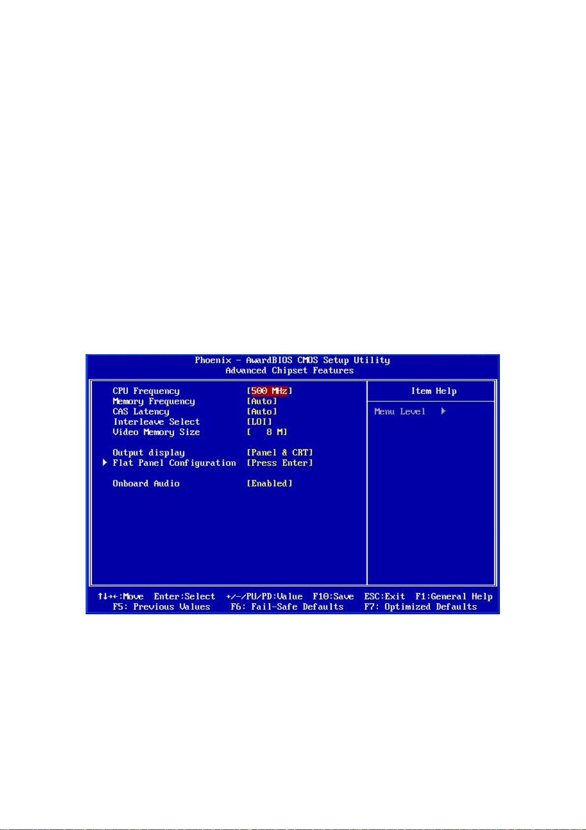
EX-93821/EX-93823 Flat Panel PC
Small Logo (EPA) Show [Disabled]
Use the Small Logo (EPA) Show option to specify if the Environmental Protection
Agency (EPA) logo appears during the system boot-up process. If enabled, the boot up
process may be delayed.
Disabled
Enabled
(Default) EPA logo does not appear during boot up.
EPA logo appears during boot up.
5.4 Advanced Chipset Features
Use the Advanced Chipset Features menu (BIOS Menu 4) to change chipset
configuration options.
BIOS Menu 4: Advanced Chipset Features
Page 76
Page 77

CPU Frequency [500MHz]
Use the CPU Frequency option to set the CPU frequency. The CPU Frequency options
are:
Auto
200MHz
333MHz
400MHz
433MHz
500MHz (Default)
Memory Frequency [Auto]
Use the Memory Fre quency option to set the frequency of the installed DRAM modules.
The Memory Frequency options are:
Auto (Default)
100MHz
133MHz
166MHz
200MHz
CAS Latency [Auto]
Use the CAS Latency Time option to set the Column Address Strobe (CAS) delay time.
The CAS Latency Time options are:
Auto (Default)
1.5 nanoseconds
2.0 nanoseconds
2.5 nanoseconds
3.0 nanoseconds
3.5 nanoseconds
Interleave Select [LOI ]
Use the Interleave Select option to specify how the cache memory is interleaved.
Page 77
Page 78

EX-93821/EX-93823 Flat Panel PC
LOI
HOI
(Default) Low order interleaving (LOI) of memory occurs.
High order interleaving (HOI) of memory occurs.
Video Memory Size [8M]
Use the
Video Memory Size
video graphics device. The
None
8M (Default)
16M
32M
64M
128M
254M
option to determine how much memory is allocated to the
Video Memory Size
Output Display [Panel & CRT]
options are:
Use the Output Display configuration to specify the display devices the system is
connected to. The Output Display options are:
Flat Panel
CRT
Panel & CRT (Default)
Flat Panel Configuration [Press Enter]
Use the Flat Panel Configuration option to open the Flat Panel Configuration menu. The
Flat Panel Configuration options are shown in Section 5.4.1.
OnBoard Audio [Enabled]
Use the
OnBoard Audio
Disabled
option to enable or disable the onboard codec.
The onboard codec is disabled.
Page 78
Page 79
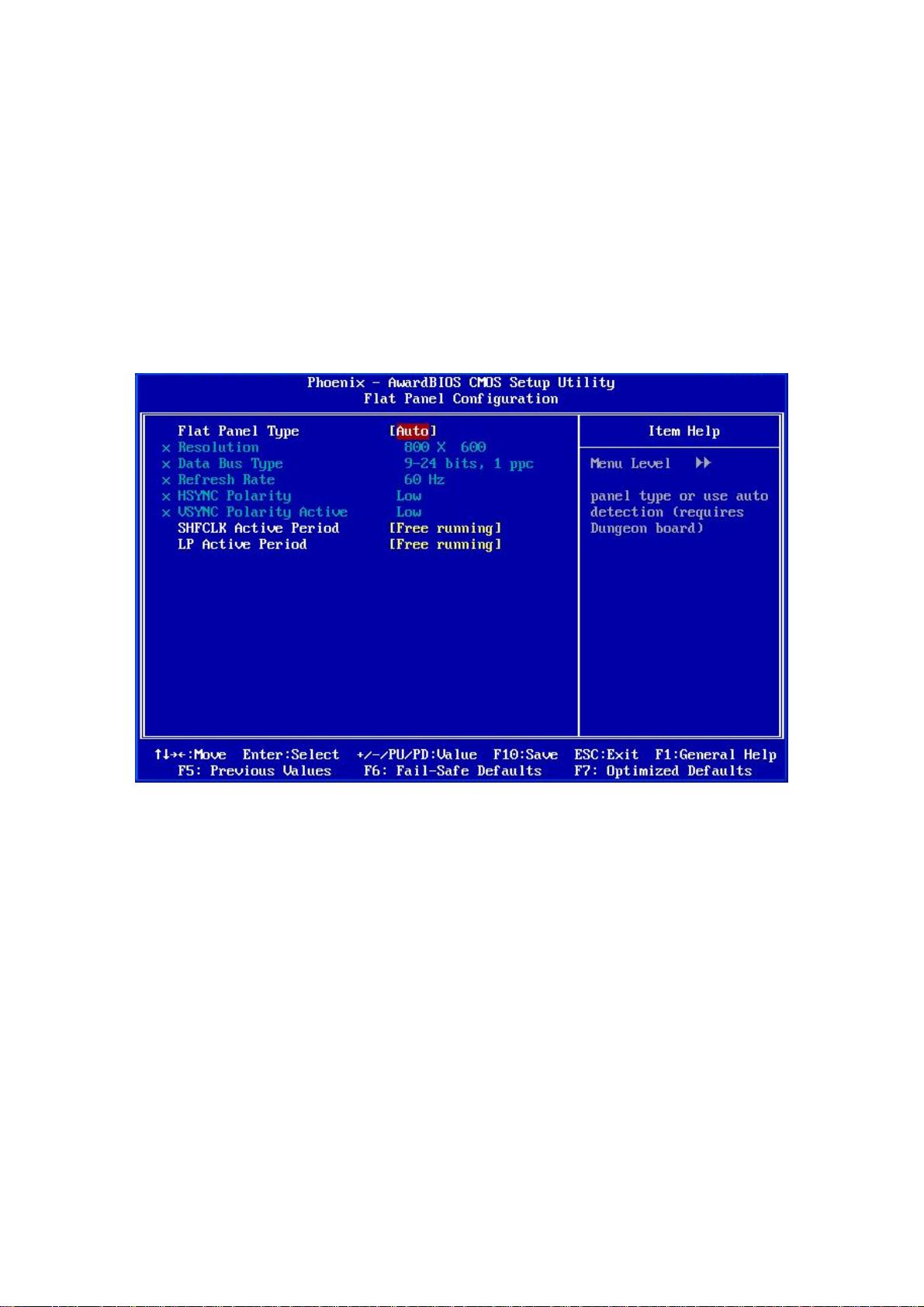
Enabled
(Default) The onboard codec is detected and enabled.
5.4.1 Flat Panel Configuration
Use the Flat Panel Configuration menu (BIOS Menu 5) to set the configuration settings
for the flat panel screen connected to the system.
BIOS Menu 5: Flat Panel Configuration
Flat Panel Type [Auto]
Use the
system.
TFT
LVDS
Auto
Flat Panel Type
Specifies the system is connected to a TFT display.
Specifies the system is connected to an LVDS display.
(Default) The system detects the display type and the display
option to specify the type of flat panel screen connected to the
Page 79
Page 80

Resolution [800 x 600]
EX-93821/EX-93823 Flat Panel PC
settings.
The
Resolution
. Use the
Auto
option can only be configured if the
Resolution
option to set the resolution of the flat panel screen connected
Flat Panel Type
option is not set to
to the system. The Resolution options are:
320 x 240
640 x 480
800 x 600 (Default)
1024 x 768
1152 x 864
1280 x 1024
1600 x 1200
Data Bus Type [9 – 24 bits, 1 ppc]
The Data Bus Type option can only be configured if the Flat Panel Type option is not set
to Auto. Use the Data Bus Type option to set the bus type and the data bus width used to
transfer data between the system and the flat panel screen connected to the system. The
Page 80
Data Bus Type options are:
9-24 bits, 1 ppc (Default)
18, 24 bits, 2 ppc
Refresh Rate [60Hz]
The Refresh Rate option can only be configured if the Flat Panel Type option is not set to
Auto. Use the Refresh Rate option to set the screen refresh rate required by the panel
connected to the system. Check the documentation that came with the panel before
setting this option. The
60Hz (Default)
70Hz
72Hz
Refresh Rate
options are:
Page 81

75Hz
85Hz
90Hz
100Hz
HSYNC Polarity [Low]
The HSYNC Polarity option can only be configured if the Flat Panel Type option is not
set to Auto. Use the HSYNC Polarity option to set the polarity of the HSYNC signal to the
panel. The HSYNC Polarity options are:
High
Low (Default)
VSYNC Polarity Active [Low]
The VGSYNC Polarity Active option can only be configured if the Flat Panel Type option
is not set to
VSYNC signal to the panel. The
High
Low (Default)
Auto
. Use the
VGSYNC Polarity Active
VGSYNC Polarity Active
option to set the polarity of the
options are:
SHFCLK Active Period [Free Running]
Use the SHFCLK Active Period option to set the SHFCLK. The SHFCLK Active Period
options are:
Active Only
Free running (Default)
LP Active Period [Free Running]
Use the LP Active Period option to set the LDE/MOD signal to the panel. The LP A ctive
Period options are:
Active Only
Free running (Default)
Page 81
Page 82
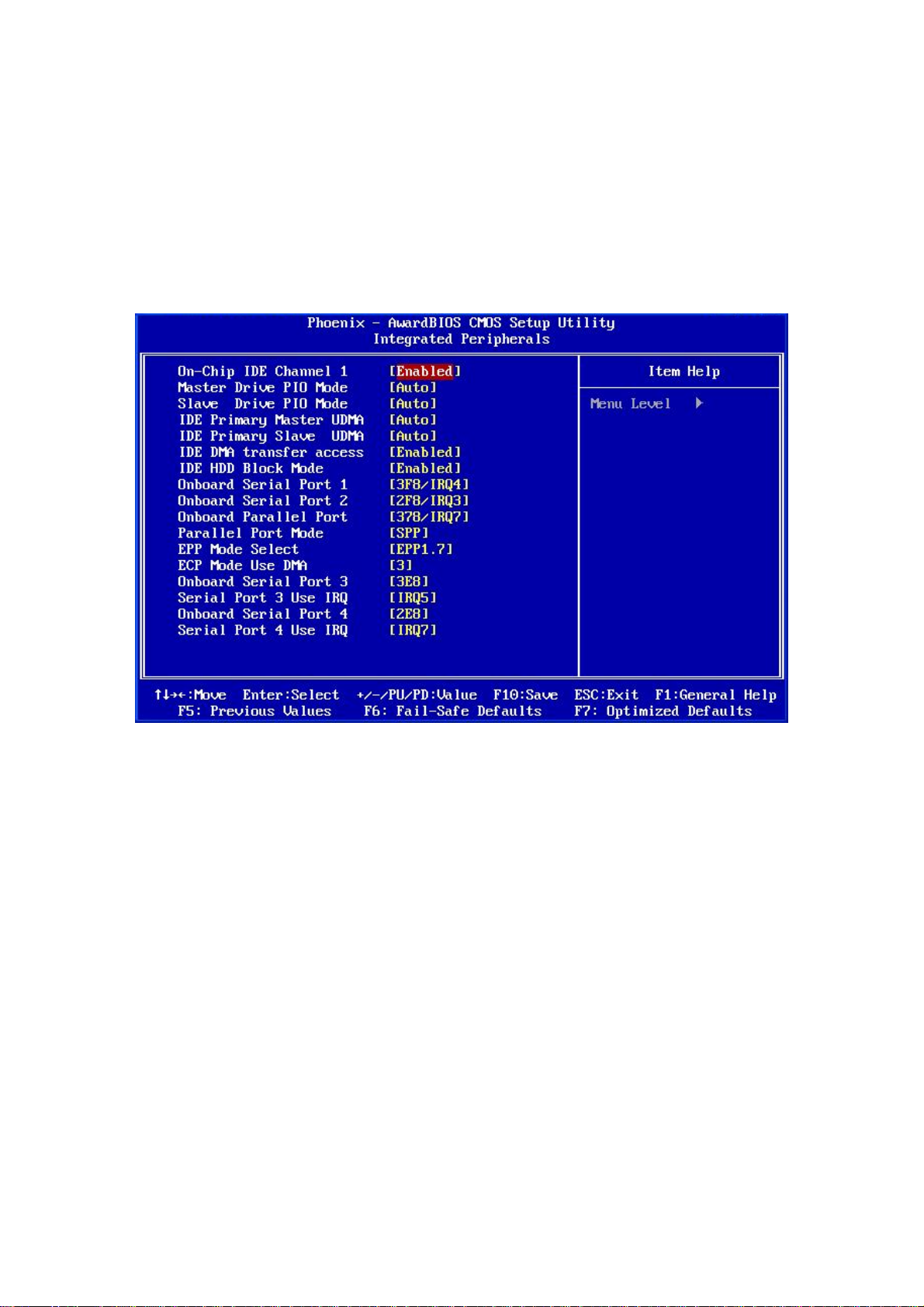
EX-93821/EX-93823 Flat Panel PC
5.5 Integrated Peripherals
Use the Integrated Peripherals menu (BIOS Menu 6) to change the configuration options
for the attached peripheral devices.
BIOS Menu 6: Integrated Peripherals
On-Chip IDE Channel 1 [Enabled]
Use the On-Chip IDE Channel 1 option to specify if the system uses the integrated
primary IDE channel or not.
Disabled
Enabled
Drive PIO Mode [Auto]
Use the Drive PIO Mode options below to select the Programmed Input/Output (PIO)
mode for the following HDDs:
Page 82
The primary IDE channel is not used.
(Default) The primary IDE channel is used.
Page 83

Master Drive PIO Mode
Slave Drive PIO Mode
Auto
Mode 0
Mode 1
Mode 2
Mode 3
Mode 4
IDE UDMA [Auto]
Use the IDE UDMA option below to select the Ultra DMA (UDMA) mode for the following
HDDs:
IDE Primary Master UDMA
IDE Primary Slave UDMA
(Default) The computer selects the correct mode.
PIO mode 0 selected with a maximum transfer rate of 3.3MBps.
PIO mode 1 selected with a maximum transfer rate of 5.2MBps.
PIO mode 2 selected with a maximum transfer rate of 8.3MBps.
PIO mode 3 selected with a maximum transfer rate of 11.1MBps.
PIO mode 4 selected with a maximum transfer rate of 16.6MBps.
Disabled
Auto
IDE DMA transfer access [Enabled]
Use the
devices connected to the system.
IDE DMA transfer access
Disabled
Enabled
The UDMA for the HDD device is disabled.
(Default) The computer selects the correct UDMA.
All IDE drive DMA transfers are disabled. The IDE drives
(Default) All IDE drive DMA transfers are enabled.
option to enable or disable DMA support for IDE
use PIO mode transfers.
Page 83
Page 84

EX-93821/EX-93823 Flat Panel PC
IDE HDD Block Mode [Enabled]
If the drive connected to the system supports block mode, use the IDE HDD Block Mode
option to enable the system to detect the optimal number of block read/writes per sector
the system IDE drive can support. Block mode is also called block transfer, multiple
commands, or multiple sector read/write.
Disabled
Enabled
Block mode is not supported.
(Default) Block mode is supported.
Onboard Serial Port 1 [3F8/IRQ4]
Use the Onboard Serial Port 1 option to select the I/O address and IRQ for the onboard
serial port 1. The serial port can be disabled or the I/O address and the IRQ can be
automatically selected by the BIOS. The Onboard Serial Port 1 options are:
Disabled
3F8/IRQ4 (Default)
2F8/IRQ3
3E8/IRQ4
2E8/IRQ3
Auto
Onboard Serial Port 2 [2F8/IRQ3]
Page 84
Use the Onboard Serial Port 2 option to select the I/O address and IRQ for the onboard
serial port 2. The serial port can be disabled or the I/O address and the IRQ can be
automatically selected by the BIOS. The
Disabled
3F8/IRQ4
2F8/IRQ3 (Default)
3E8/IRQ4
2E8/IRQ3
Auto
Onboard Serial Port 2
options are:
Page 85

Onboard Parallel Port [378/IRQ7]
Use the Onboard Parallel Port option to specify a logical LPT port address and
corresponding interrupt for the physical parallel port. The Onboard Paralle l Port options
are:
Disabled
378/IRQ7 (Default)
278/IRQ5
3BC/IRQ7
Parallel Port Mode [SPP]
Use the Parallel Port Mode option to select parallel port operation mode.
SPP
EPP
ECP
(Default) The parallel port operates in the standard parallel port
(SPP) mode. This parallel port mode works with most
parallel port devices but is slow.
The parallel port operates in the enhanced parallel port
mode (EPP). The EPP mode supports bi-directional
communication between the system and the parallel
port device and the transmission rates between the two
are much faster than the SPP mode.
The parallel port operates in the extended capabilities
port (ECP) mode. The ECP mode supports
bi-directional communication between the system and
the parallel port device and the transmission rates
between the two are much faster than the SPP mode.
ECP+EPP
Normal
The parallel port is compatible with both ECP and EPP
devices.
Page 85
Page 86

EPP Mode Select [EPP1.7]
The EPP Mode Select option is only available if the Parallel Port Mode option is set to
EPP mode. Use the EPP Mode Select option to select the parallel port mode standard for
the parallel port.
EX-93821/EX-93823 Flat Panel PC
EPP1.9
EPP1.7
ECP Mode Use DMA [3]
The ECP Mode Use DMA option is only available if the Parallel Port Mode option is set
to ECP mode. Use the ECP Mode Use DMA option to specify the DMA channel the
parallel port must use in the ECP mode.
1
3
Onboard Serial Port 3 [3E8]
Use the Onboard Serial Port 3 option to select the I/O address for the onboard serial port
3. The serial port can be disabled or the I/O address can be automatically selected by the
EPP 1.9 is selected as the EPP standard.
(Default) EPP 1.7 is selected as the EPP standard.
The parallel port uses DMA Channel 1 in ECP mode.
(Default) The parallel port uses DMA Channel 3 in ECP mode.
BIOS. The Onboard Serial Port 3 options are:
Disabled
3F8
2F8
3E8 (Default)
2E8
Serial Port 3 Use IRQ [IRQ5]
Use the Serial Port 3 Use IRQ option to select the IRQ for the onboard serial port 3. The
serial port can be disabled or the IRQ can be automatically selected by the BIOS. The
Serial Port 3 Use IRQ options are:
Page 86
Page 87

Disabled
IRQ5 (Default)
IRQ7
Onboard Serial Port 4 [2E8]
Use the Onboard Serial Port 4 option to select the I/O address for the onboard serial port
4. The serial port can be disabled or the I/O address can be automatically selected by the
BIOS. The Onboard Serial Port 4 options are:
Disabled
3F8
2F8
3E8
2E8 (Default)
Serial Port 4 Use IRQ [IRQ7]
Use the Serial Port 4 Use IRQ option to select the IRQ for the onboard serial port 4. The
serial port can be disabled or the IRQ can be automatically selected by the BIOS. The
Serial Port 4 Use IRQ options are:
IRQ5
IRQ7 (Default)
5.6 Power Management Setup
Use the Power Management Setup menu (BIOS Menu 7) to set the BIOS power
management and saving features.
Page 87
Page 88
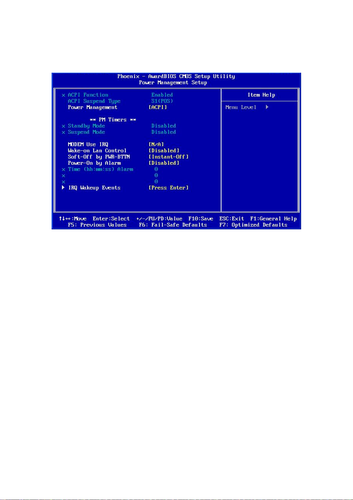
EX-93821/EX-93823 Flat Panel PC
BIOS Menu 7: Power Management Setup
ACPI Function [Enabled]
Use the ACPI Function to enable the ACPI (Advanced Configuration and Power Interface)
function.
Disabled
Enabled
ACPI function disabled.
(Default) ACPI function enabled.
Page 88
Page 89

ACPI Suspend Type [S1(POS)]
Use the ACPI Suspend Type BIOS option to specify the sleep state the system enters
when not being used.
S1 (POS)
S3 (STR)
S1 & S3
Power Management [ACPI]
Use the
system.
Power Management
Disabled
(Default) System appears off. The CPU is stopped; RAM is
System appears off. The CPU has no power; RAM is in
Both suspend modes are implemented
All power management options are turned off. The only
refreshed; the system is running in a low power mode.
slow refresh; the power supply is in a reduced power
mode.
option to set the power management type used by the
user configurable options are the power button and
alarm settings.
Legacy
APM
ACPI
x Standby Mode [Disabled]
The
Standby Mode
to Legacy. The
before the system enters standby mode. The Standby Mode options are:
Standby Mode
Standby and suspend modes can be set.
Advanced power management (APM) is activated
(Default) Advanced Configuration and Power Interface (ACPI) is
activated.
option can only be selected if the
specifies the amount of time the system can be inactive
Power Management
option is set
Page 89
Page 90

EX-93821/EX-93823 Flat Panel PC
Disabled (Default)
1 Sec
5 Sec
10 Sec
15 Sec
30 Sec
45 Sec
1 Min
5 Min
10 Min
15 Min
30 Min
45 Min
60 Min
90 Min
120 Min
x Suspend Mode [Disabled]
The Suspend Mode option can only be selected if the Power Manage ment option is set
to Legacy. The Suspend Mode specifies the amount of time the system can be inactive
before the system enters suspend mode. The Suspend Mode options are:
Disabled (Default)
1 Sec
5 Sec
10 Sec
15 Sec
30 Sec
45 Sec
1 Min
5 Min
Page 90
10 Min
15 Min
30 Min
Page 91

45 Min
60 Min
90 Min
120 Min
Modem Use of IRQ
Use the Modem Use of IRQ to select the IRQ address for the system modem. The
following IRQ addresses are available.
N/A
3 (Default)
4
5
7
9
10
11
Wake-on Lan Control [Disabled]
Use the Wake-on Lan Control option to enable activity on the LAN to rouse the system
from a suspend or doze state.
Disabled
Enabled
(Default) Wake event not generated by LAN activity.
Wake event generated by LAN activity.
Soft-Off by PWR-BTTN [Instant-Off]
Use the Soft-Off by PWR-BTTN option to enabled the system to enter a very
low-power-usage state when the power button is pressed.
Instant-Off
(Default) When the power button is pressed, the system is
immediately shutdown.
Delay 4-sec
To shutdown the system the power button must be held
Page 91
Page 92

EX-93821/EX-93823 Flat Panel PC
Power-On by Alarm [Disabled]
Use the Power-On by Alarm option to specify when the computer is roused from a
suspended state.
down longer than four seconds otherwise the system
enters a low power usage state.
Disabled
Enabled
IRQ Wakeup Events [Press Enter]
To view the IRQ Wakeup Events options press E
(Default) The real time clock (RTC) cannot generate a wake
event
If selected, the following appears with values that
can be selected:
Time (hh:mm:ss) Alarm
After setting the alarm, the computer will turn itself
on from a suspend state when the alarm goes off.
NTER.
Page 92
Page 93
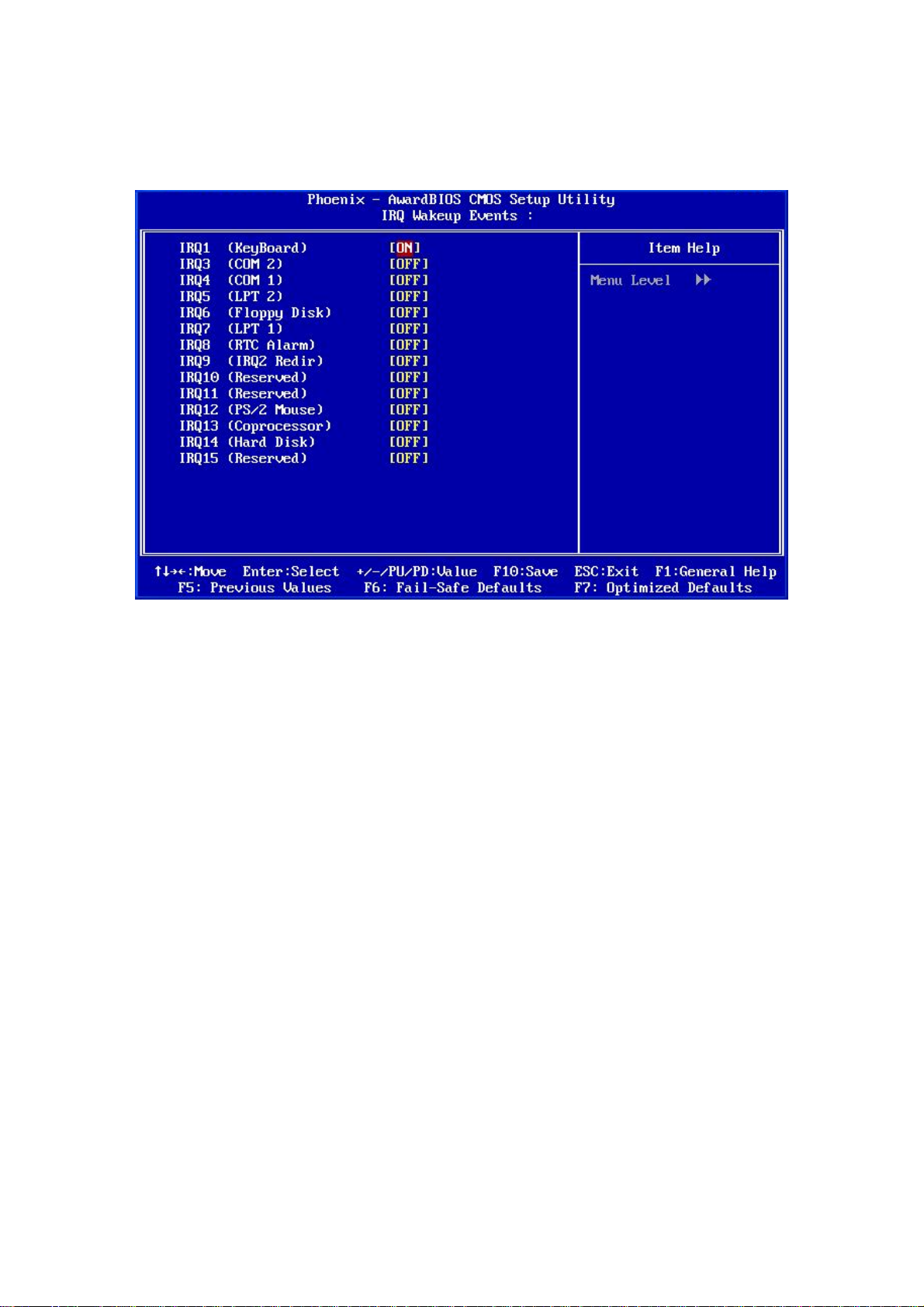
BIOS Menu 8: IRQ Wakeup Ev ents
The following IRQs can be used to generate wake events:
IRQ1 (KeyBoard) ON
IRQ3 (COM 2) OFF
IRQ4 (COM 1) OFF
IRQ5 (LPT 2) OFF
IRQ6 (Floppy Disk) OFF
IRQ7 (LPT 1) OFF
IRQ8 (RTC Alarm) OFF
IRQ9 (IRQ2 Redir) OFF
IRQ10 (Reserved) OFF
IRQ11 (Reserved) OFF
IRQ12 (PS/2 Mouse) OFF
IRQ13 (Coprocessor) OFF
IRQ14 (Hard Disk) OFF
IRQ15 (Reserved) OFF
Page 93
Page 94
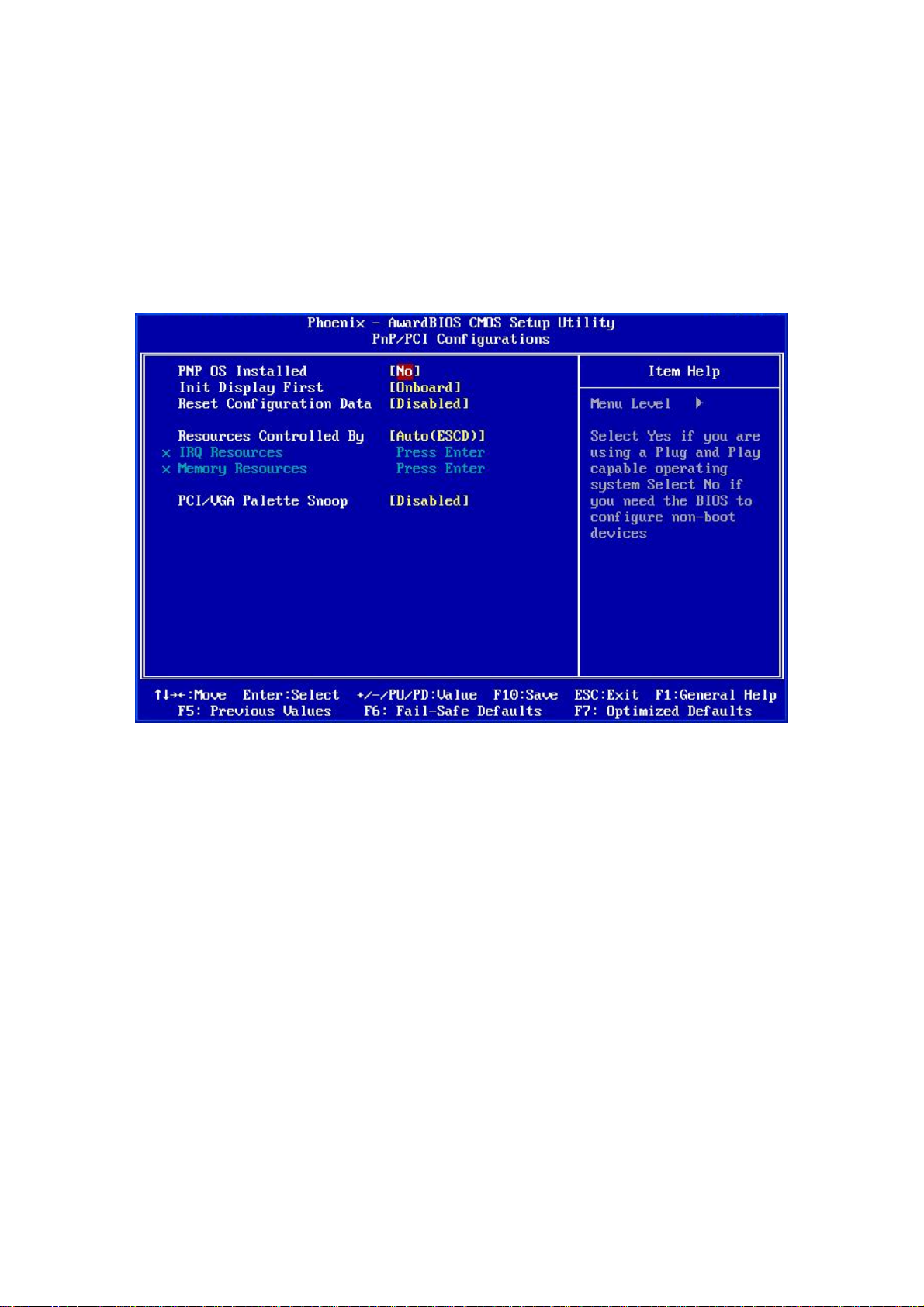
EX-93821/EX-93823 Flat Panel PC
5.7 PnP/PCI Configurations
Use the PnP/PCI Configurations menu (BIOS Menu 9) to set the plug and play, and PCI
options.
BIOS Menu 9: PnP/PCI Configurations
PNP OS Installed [No]
The PNP OS Installed option determines whether the Plug and Play devices connected to
the system are configured by the operating system or the BIOS.
Page 94
No
Yes
(Default) If the operating system does not meet the Plug and Play
specifications, BIOS configures all the devices in the system.
Set this option if the system is running Plug and Play aware
operating systems. The operating system changes the
interrupt, I/O, and DMA settings.
Page 95

Init Display First [Onboard]
Use the Init Display First option to select the primary display device.
PCI Slot
Onboard
Reset Configuration Data [Disabled]
Use the Reset Configuration Data option to reset the Extended System Configuration
Data (ESCD) when exiting setup if booting problems occur after a new add-on is installed.
Disabled
Enabled
Resources Controlled By [Auto (ESCD)]
Use the Resources Controlled By option to either manually configure all the boot and
The display connected to the PCI slot is the primary
display.
(Default) The display connected to the onboard connector is the
primary display.
(Default) ESCD will not be reconfigured
ESCD will be reconfigured after you exit setup
plug and play devices, or allow BIOS to configure these devices automatically. If BIOS is
allowed to configure the devices automatically IRQs, DMA and memory base address
fields cannot be set manually.
Auto(ESCD)
Manual
x IRQ Resources [Press Enter]
The
IRQ Resources
set to Manual.
option can only be selected if the Resources Controlled By option is
(Default) BIOS automatically configures plug and play devices as
well as boot devices.
Manually configure the plug and play devices and any
other boot devices.
Page 95
Page 96

EX-93821/EX-93823 Flat Panel PC
The IRQ Resources menu has the following options:
IRQ-3 assigned to
IRQ-4 assigned to
IRQ-10 assigned to
IRQ-11 assigned to
The above options all have the following default options.
PCI Device
Reserved
x Memory Resources [Press Enter]
The Memory Resources menu can only be accessed if the Resources Controlled By
option is set to Manual. Use Memory Resources to select a base address and the length
for the memory area used by a peripheral that requires high memory.
The menu has two configurable options:
Reserved Memory Base
Reserved Memory Length
(Default) The IRQ is assigned to legacy ISA for devices compliant
with the original PC AT bus specification, PCI/ISA PNP for
devices compliant with the Plug and Play standard
whether designed for PCI or ISA bus architecture.
The IRQ is reserved by BIOS.
PCI/VGA Palette Snoop [Disabled]
Use the PCI/VGA Palette Snoop option to enable the system to determine whether or not
some special VGA cards, high-end hardware MPEG decoders and other similar devices
are allowed to look at the VGA palette on the video card so these devices can determine
what colors are in use. This option is needed very rarely and should be left "Disabled"
unless a video device specifically requires the setting to be enabled upon installation.
Page 96
Disabled
(Default) Does not allow the graphics devices to examine the VGA
Page 97
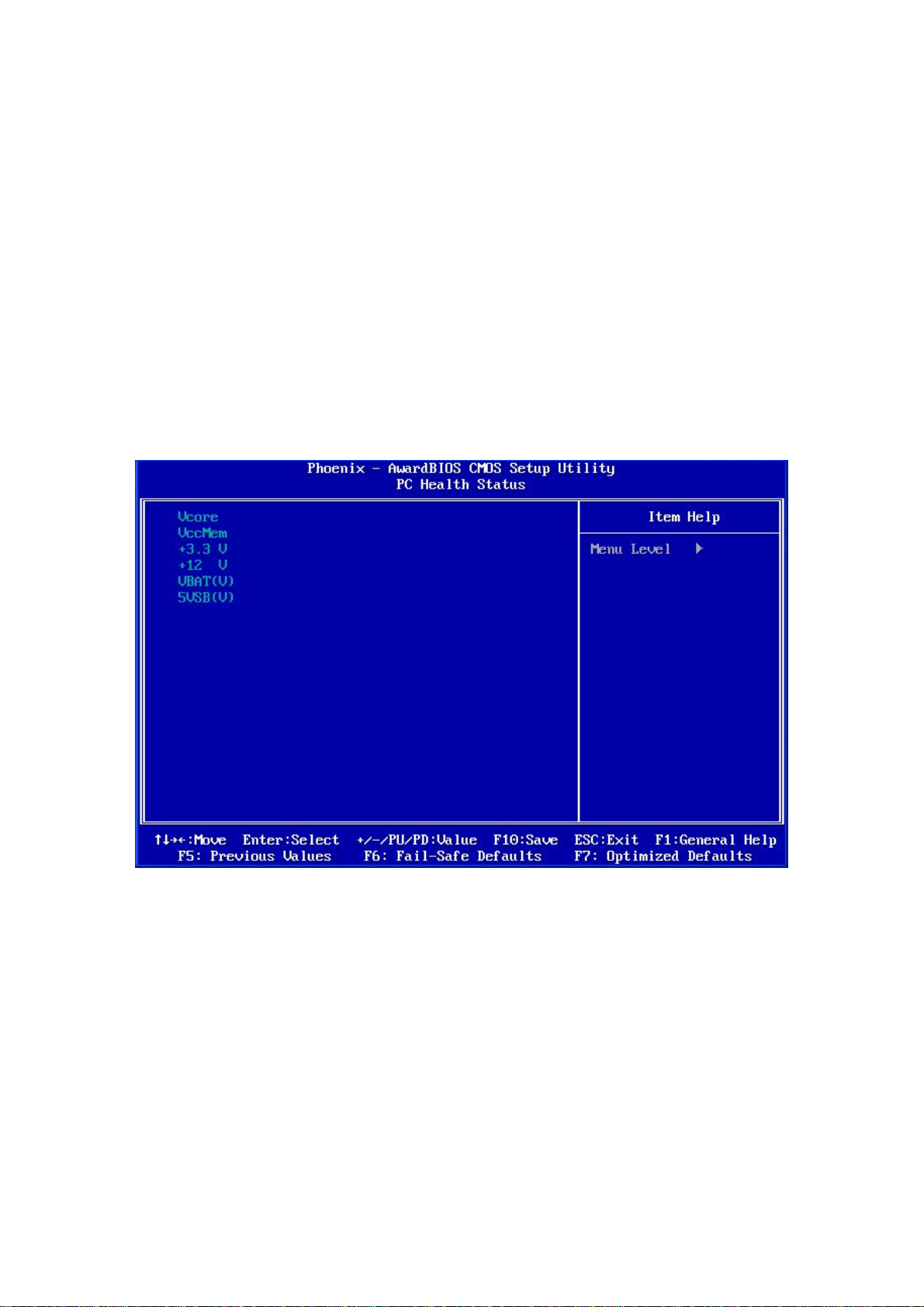
palette on the graphics card.
Enabled
Allows the graphics devices to examine the VGA palette on
5.8 PC Health Status
The PC Health Status menu (BIOS Menu 10) has no user configurable options, but
shows system operating parameters that are essential to the stable operation of the
system.
the graphics card.
BIOS Menu 10: PC Health Status
The following system parameters are monitored by the PC Health Status menu.
Voltages
The following voltages are monitored:
Vcore
VccMem
Page 97
Page 98

EX-93821/EX-93823 Flat Panel PC
+3.3 V
+12 V
VBAT(V)
5VSB(V)
Page 98
Page 99

Appendix
A
A Safety Precautions
Page 99
Page 100

EX-93821/EX-93823 Flat Panel PC
WARNING:
The precautions outlined in this chapter should be strictly followed.
Failure to follow these precautions may result in permanent damage to
the panel PC.
A.1 Safety Precautions
Please follow the safety precautions outlined in the sections that follow:
A.1.1 General Safety Precautions
Please ensure the following safety precautions are adhered to at all times.
Follow the electrostatic precautions outlined below whenever the panel PC
is opened.
Make sure the power is turned off and the power cord is disconnected
whenever the panel PC is being installed, moved or modified.
Do not apply voltage levels that exceed the specified voltage range.
Doing so may cause fire and/or an electrical shock.
Electric shocks can occur if the panel PC chassis is opened when the panel
PC is running.
Do not drop or insert any objects into the ventilation openings of the panel
PC.
If considerable amounts of dust, water, or fluids enter the panel PC, turn
off the power supply immediately, unplug the power cord, and contact the
panel PC vendor.
DO NOT:
Page 100
o Drop the panel PC against a hard surface.
o Strike or exert excessive force onto the LCD panel.
o Touch any of the LCD panels with a sharp object
o In a site where the ambient temperature exceeds the rated temperature
 Loading...