

TOPSCCC EX-92633 User Manual

EX-92633 User Manual
1
EX-92633 Box PC
User Manual
Release Date Revision
Oct. 2007 V0.1
®2005 TopsCCC. All Rights Reserved. Published in Taiwan

EX-92633 User Manual
2
Warning!_______________________________
This equipment generates, uses and can radiate radio frequency energy and if not installed and
used in accordance with the instructions manual, it may cause interference to radio
communications.
It has been tested and found to comply with the limits for a Class A computing device pursuant to
FCC Rules, which are designed to provide reasonable protection against such interference when
operated in a commercial environment. Operation of this equipment in a residential area is likely
to cause interference in which case the user at his own expense will be required to take whatever
measures may be required to correct the interference.
Disclaimer
This information in this document is subject to change without notice. In no event shall
TopsCCC be liable for damages of any kind, whether incidental or consequential, arising from
either the use or misuse of information in this document or in any related materials.
Electric Shock Hazard – Do not operate the machine with its back cover removed. There are
dangerous high voltages inside.

EX-92633 User Manual
3
Table of Contents______________________
Warning!…………………………………………………………………………….……..….2
Disclaimer………………………………………………………………….…………………2
Chapter 1 Getting Started
1.1 Features…....………………….………………………….…………..…...…4
1.2 Specifications………………………………………….………….……...…..4
1.3 Dimensions…………………………………...……………….…………......5
1.4.Mainboard…..………………………………………….……………..…...7
1.5 Safety Precautions……….………………….………….……….……….….9
1.6 Brief Description of EX-92633………………………….…………………10
Chapter 2 Hardware Installation
2.1 Installation of CPU...…...………………………………….……………11
2.2 Installation of HDD...…...………………………………….……………12
2.3 Installing the Memory.….………………………………….……………14
2.4 Installing the Jumpers………………………….………….……………15
2.5 Connectors on the Mainboard…..………………………….……………19
Chapter 3 Installations of BIOS
3.1 BIOS Setup……………………………………………….……………23
Chapter 4 Installations of Drivers
4.1 Installations of Drivers………………………………….….….……………42
Figures
Figure 1.1: Dimensions ……………………………………………………...6
Figure 1.2: Mainboard Overview …………………………………………...7
Figure 1.3: Rear View…..………………………..….………………………10

EX-92633 User Manual
4
Chapter 1_____________________________
1.1 Features
z Intel Celeron M / Pentium M, up to 1.8GHz
z Fanless design
z Intel 852GM + ICH4
z 1 x 184-pin DDR DIMM with up to 1GB
z 2 x 10/100 Ethernet LAN, 1 x VGA connector
z 3 x COM ports & 4 x USB ports
z 1 x AC’97 Line-Out / 1 x MIC
z 1 x 2.5” anti-vibration slim HDD & 1 x CF Socket on board
z Support Single 11~28V/DC Input, support AT/ATX mode
1.2 Specifications
System
CPU:
Socket 479 for Intel Celeron M / Pentium M, up to 1.8GHz
Chipset:
Intel 852GM + ICH4
System Memory:
DDR DIMM with up to 1GB
DRAM Socket:
One 184-pin DDR DIMM
Drive Bay:
1 x 2.5” anti-vibration slim HDD
BIOS:
Award Flash
Watchdog Timer:
Generates system reset, 256 levels
I/O Port:
3 x COM ports, 4 x USB2.0 ports, 2 x PS/2 keyboard and mouse ports, 1x VGA, Audio Jack (AC’97,
Line-Out/MIC),
RJ-45 LAN Port:
2 x 10/100Mbps
VGA:
Built-in Intel® 82852GM+ICH4

EX-92633 User Manual
5
Certifications:
FCC & CE Class A certified
Mechanical
Construction:
Heavy steel & Alu. Heatsink
Color:
Blue
Dimensions:
240(W) x 80(D) x 230mm(H)
Power Supply:
11~28V/DC Input, support AT/ATX mode
Environment
Operating temperature:
0~60 C°
Storage temperature:
-20°C ~ 80 C°
Relative humidity:
10~90% @ 40 C non° -condensing
Vibration:
5~17Hz, 0.1” double amplitude displacement
17~640Hz, 1.5G acceleration peak to peak
Shock:
10G acceleration peak to peak (11 millimeters)

EX-92633 User Manual
6
1.3 Dimensions
Figure 1.1: Dimensions of the EX-92633
EX-92633 User Manual
7
1.4 Mainboard
Introducing the Motherboard
Figure 1.2: Mainboard Overview
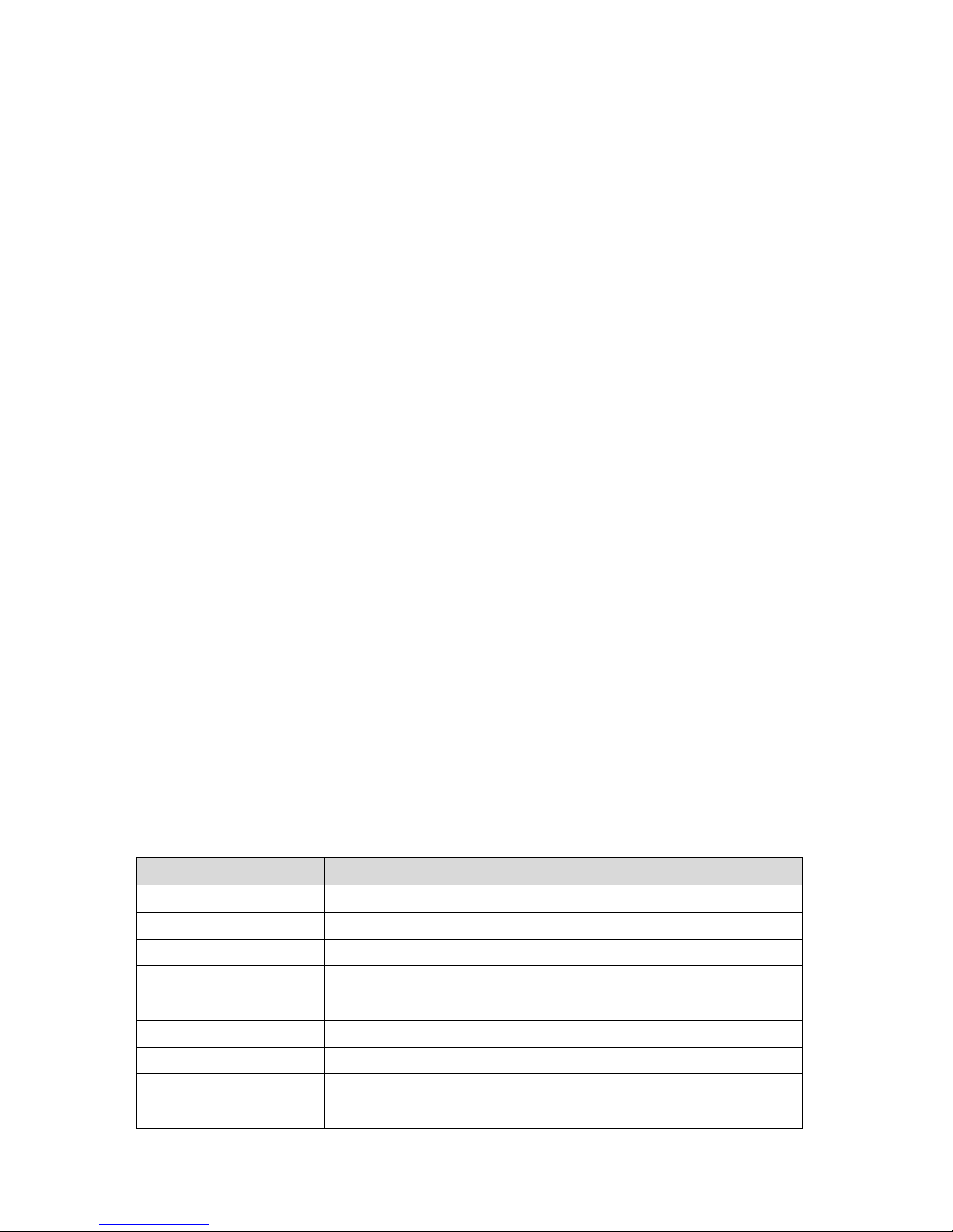
Table of Motherboard Components
LABEL COMPONENT
1 Processor 479 socket for Pentium M/Celeron M CPUs
2 CPU_FAN CPU cooling fan connector
3 DIMM1 184-pin DDR SDRAM slot
4 SYS_FAN System cooling fan connector
5 CF_PWR CF power voltage jumper
6 ATX_PWR Standard 20-pin ATX power connector
7 LPT LPT pin header
8 FDD Floppy disk drive connector
9 IDE2 Secondary IDE connector

EX-92633 User Manual
8
10 IDE1 Primary IDE connector
11 PANEL Front Panel switch/LED header
12 CLR_CMOS Clear CMOS jumper
13 PCI slot 32-bit PCI add-on card slot
14 USB3 Front Panel USB header
15 DIO DIO port header
16 AUDIO Front panel Audio header
17 LVDS2 Low Voltage Differential Signaling Transmitter Channel B
18 LVDS1 Low Voltage Differential Signaling Transmitter Channel A
19 LVDS_PWR Low Voltage Differential Signaling Power header
20 COM4 Serial port header
21 JP2 COM3/COM4 Ring function selector
22 JP1 COM1/COM2 Ring function selector
23 SCN1 C.F. Socket for installing C.F.(Compact Flash) card
Specifications
System
CPU:
Socket 479 for Intel Celeron M / Pentium M, up to 1.8GHz
CPU FSB Frequency:
400MHz
Chipset:
Intel 852GM + ICH4
DRAM:
1 x 184 pin DDR DIMM max. up to 1GB
BIOS:
Award BIOS with 4 Mbit Flash ROM, ACPI supported
Watchdog:
Generates system reset; 256 levels
Power Supply:

EX-92633 User Manual
9
11~28V/DC Input, support AT/ATX mode
Dimensions:
170mm x 170mm (6.69 x 6.69 inches)
Environment
Operating Temperature:
0~ 60° ℃ (32°~ 140℉)
Storage Temperature:
-20°~ 80℃ (68°~ 176℉)
Relative Humidity:
10~90% (non-condensing)
1.5 Safety Precautions
Follow the messages below to avoid your systems from damage:
* Avoid your system from static electricity on all occasions.
* Prevent electric shock. Don‘t touch any components of this card when the card is power-on.
Always disconnect power when the system is not in use.
*Disconnect power when you change any hardware devices. For instance, when you connect
a jumper or install any cards, a surge of power may damage the electronic components or
the whole system.

EX-92633 User Manual
10
1.6 Brief Description of the EX-92633
The EX-92633 is a Fan-less High-efficiency Thermal Solution and ultra-compact standalone Box PC,
powered by an Intel Celeron M / Pentium M, up to 1.8GHz, and supporting 4 USB 2.0 ports, 3x COM
Ports, 1 x VGA and Audio etc. It is ideal for kiosks, POS systems, airport terminal controllers, digital
entertainments, etc. and running factory operations from small visual interface and maintenance
applications to large control process applications. The EX-92633 works very well along with any of our
Display Monitor series. It absolutely can provide an easy way to perform control and field maintenance.
It comes with a DC11~28V wide-ranging power input.
Figure 1.3: Rear View of EX-92633

EX-92633 User Manual
11
Chapter 2 Hardware Installation
2.1 Installation of CPU
This section provides information on how to use the jumpers and connectors on the mainboard in
order to set up a workable system.
2.1.1 Installing the CPU
The mainboard supports a Socket 479 processor socket for Intel Pentium M or Celeron M processors.
The processor socket comes with a screw to secure the processor. As shown in the left picture below,
loosen the screw first before inserting the processor. Place the processor into the socket by making
sure the notch on the corner of the CPU corresponds with the notch on the inside of the socket. Once
the processor slides into the socket, fasten the screw.
Figure 2.1: Installation of CPU
Note:
Make sure the heat sink and the top surface of the CPU are in total contact to
avoid the overheating problem that would cause your system to hang or be unstable.

EX-92633 User Manual
12
2.2 Installation of HDD
2.2.1 Removal of HDD Bracket
To remove the HDD bracket from its position,
j
ust unscrew the 4 screws as shown in the
picture.
2.2.2 Connecting Cable to HDD
Connect the cable to the HDD, making sure
that the red stripe of the cable is on the right
side (if connected with the top of the HDD
facing upward).

EX-92633 User Manual
13
2.2.3 Tightening HDD
Tightly fasten the four screws as circled to
secure the HDD.
2.2.4 Installing HDD
Get the 4 screws tightened onto the chassis
as shown in the picture.
EX-92633 User Manual
14
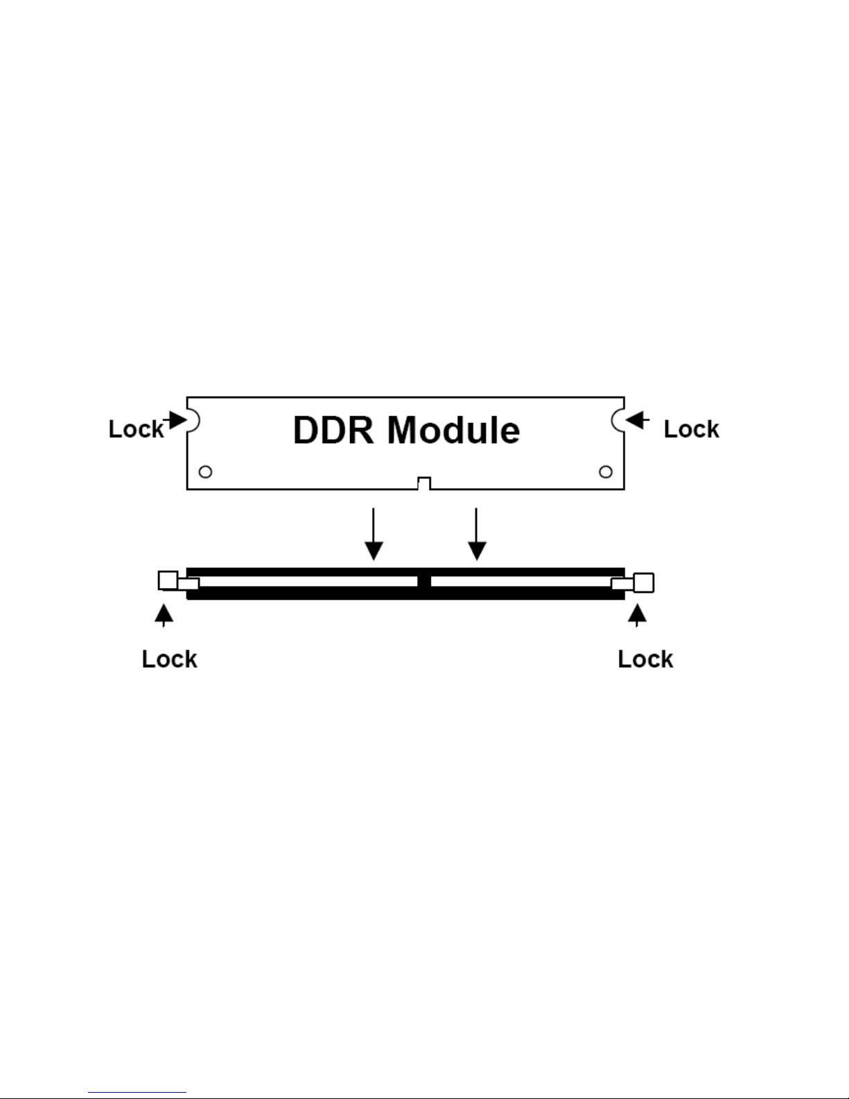
2.3 Installing the Memory
The mainboard supports one DDR memory socket for a maximum total memory of 1GB. The memory
module capacities supported are 128MB, 256MB, 512MB and 1GB. The following figure shows the
supported DDR DIMM configurations. The Intel 855GME supports configurations defined in the
JEDEC DDR DIMM specifications only. Non-JEDEC standard DIMMs such as double-sided x16 DDR
SDRAM DIMMs are not supported.
To install the DDR modules, locate the memory slot on the board and perform the following steps:
1. Hold the DDR module so that the key of the DDR module is aligned with those on the memory slot.
2. Gently insert the DDR module into the memory slot and lock the two levers in place.
3. To remove the DDR module, press the two levers with both hands.
Figure 3.3: Installation of Memory Module
EX-92633 User Manual
15
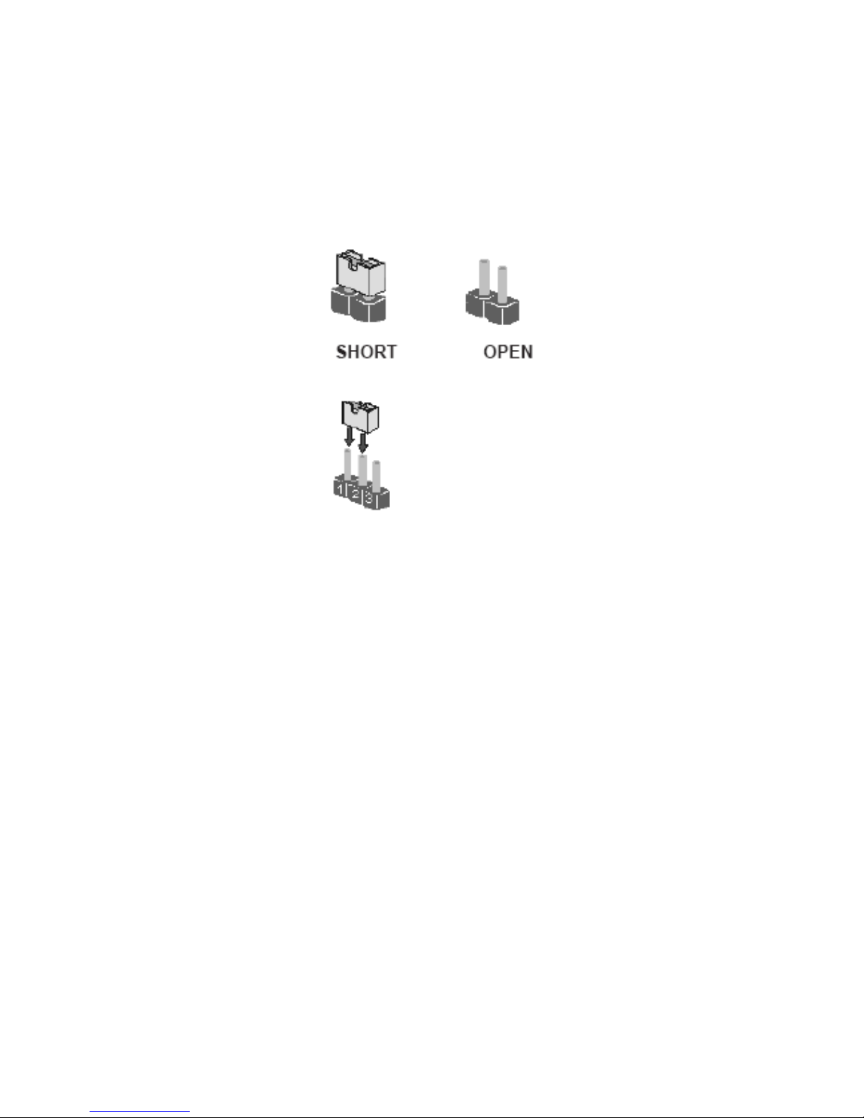
2.4 Installing the Jumpers
Use the motherboard jumpers to set system configuration options. Jumpers with more than one pin
are numbered. When setting the jumpers, ensure that the jumper caps are placed on the correct pins.
The illustrations show a 2-pin jumper. When the jumper cap is placed on both pins, the jumper is
SHORT. If you remove the jumper cap, or place the jumper cap on just one pin, the jumper is OPEN.
This illustration shows a 3-pin jumper. Pins 1 and 2 are SHORT
Checking Jumper Settings
The following illustration shows the location of the motherboard jumpers. Pin 1 is labeled.
EX-92633 User Manual
16
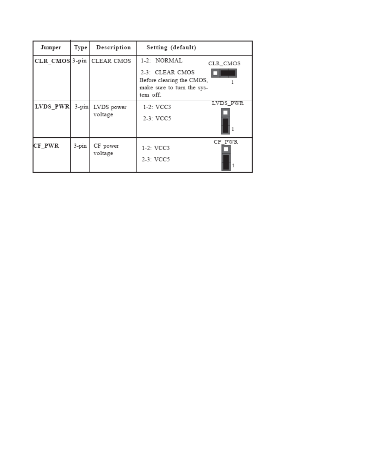
Jumper Settings
Connecting Case Components
After you have installed the motherboard into a case, you can begin connecting the motherboard
components. Refer to the following:
1 Connect the CPU cooling fan cable to CPU_FAN.
2 Connect the system cooling fan connector to SYS_FAN.
3 Connect the case switches and indicator LEDs to the PANEL.
4 Connect the standard power supply connector to ATX_POWER.
 Loading...