

TOPSCCC EX-92622A User Manual

EX-92622A User Manual
1
EX-92622A Box PC
User Manual
Release Date Revision
Apr. 2009 V1.0
®2005 TOPSCCC Technology, Inc. All Rights Reserved. Published in Taiwan
TOPSCCC Technology, Inc.
5F, NO. 12, ALLEY 345, Yang-Guang ST. , Nei-Hu, Taipei, Taiiwan R.O.C
Tel:886-2-27999080 Tel:886-2-26585042, 26575516 E-mail: support@topsccc.com URL:
www.topsccc.com

EX-92622A User Manual
2
Warning!___________________________________
This equipment generates, uses and can radiate radio frequency energy and if not installed and
used in accordance with the instructions manual, it may cause interference to radio communications.
It has been tested and found to comply with the limits for a Class A computing device pursuant to
FCC Rules, which are designed to provide reasonable protection against such interference when
operated in a commercial environment. Operation of this equipment in a residential area is likely
to cause interference in which case the user at his own expense will be required to take whatever
measures may be required to correct the interference.
Disclaimer
This information in this document is subject to change without notice. In no event shall TOPSCCC
Technology Inc. be liable for damages of any kind, whether incidental or consequential, arising from
either the use or misuse of information in this document or in any related materials.
Electric Shock Hazard – Do not operate the machine with its back cover removed. There are
dangerous high voltages inside.

EX-92622A User Manual
3
Table of Contents______________________
Warning!…………………………………………………………………………….……..….2
Disclaimer………………………………………………………………….………………….2
Chapter 1 Getting Started
1.1 Brief Description of EX-92622A……………………………......................5
1.2 Specifications………………………………………….………………...….6
1.3 Dimensions…………………………………...……………………………..8
1.4 Installation of PCI Expansion Add on Cards………………….................9
1.5 Installation of HDD…………………………….…………………...............10
Chapter 2 Hardware Installation
2.1 Main Board……………………………………………………………........12
2.2 Installing the CPU…………………………………….………………...….13
2.3 Installing the Memory………………………...……………………………14
2.4 Installing the Jumpers..........................................................................15
2.5 Installing the Connectors.......................................................................29
Chapter 3 BIOS Setup
3.1 Entering Setup…………………………………………………………….43
3.2 Control Keys…………………………..……….………………………....43
3.3 Getting Help……………….…………………………………………...44
3.4 The Main Menu…..……………………………………………………43
3.5 Standard CMOS Setup Menu……………………………………45
3.6 Advanced BIOS Features…………………………………………..46
3.7 Advanced Chipset Features………………………………………….51
3.8 Integrated Peripherals……………………………………………………53
3.9 Power Management Setup………………………………………….56
3.10 PnP/PCI Configuration Setup………………………….……………..59
3.11 PC Health Status…………..………………………………………..60
3.12 Frequency/voltage Control……………………………………………..61
3.13 Load Optimized Defaults..………………………………………………..62
3.14 Set supervisor/User Password………………………………………..63

EX-92622A User Manual
4
3.15 Save & Exit setup………………………………………………………..63
3.16 Exit Without Saving...………………………………………………..64
Chapter 4 Driver Installation
4.1 Intel Chipset Software Installation Utility.……………………………..66
4.2 VGA Driver Installation………………………………………………….68
4.3 LAN Driver Installation…………………………………………………….71
4.4 AC’97 Codec Audio Driver Installation…………………………………..76
Figures
Figure 1.1: Front View of EX-92622A ……………………….……………….5
Figure 1.2: Rear View of EX-92622A..……………………….……….………5
Figure 1.3: Dimension of EX-92622A…….……………………….…………..8
Figure 2.1: Mainboard Overview………………………………..……………..12
Figure 2.2: Installation of CPU………….……………………………...……...13
Figure 2.3: Installation of Memory Module……...……………………..……. 14
Figure 2.4: Location of Jumper……..……………………………………..…15
EX-92622A User Manual
5
Chapter 1_______ System
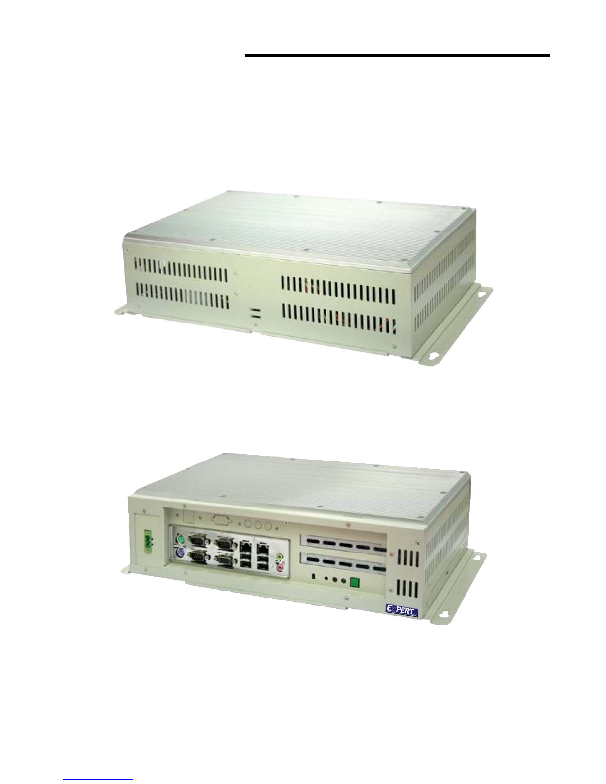
1.1 Brief Description of the EX-92622A
The EX-92622A is a fanless, rugged and ultra-compact standalone box PC. It is powered by Intel
Celeron M 1.5GHz up to Pentium M 1.8GHz processor and thus, it offers optimal heat dissipation and
low-power consumption without sacrificing the speed you need.
Figure 1.1: Front View of EX-92622A
Figure 1.2: Rear View of EX-92622A

EX-92622A User Manual
6
1.3 Specifications
System
CPU:
Intel Celeron M 1.5GHz processor/Pentium M 1.8GHz processor / 400MHz FSB
Chipset:
Intel® 910GMLE & ICH6M
System Memory:
2 x 240-pin DDR2 DIMM sockets / Maximum to 2 GB DDR2 memory
Storage:
Support 1 x 2.5” SATA HDD, 1 x on board CompactFlash Type II Scoket (optional )
BIOS:
Phoenix-Award BIOS, Y2K compliant
4Mbit Flash, DMI, Plug and Play
SmartView for multiple LCD type selection, display mode option and application extension features
RPL/PXE Ethernet Boot ROM
“Load Optimized Default” to backup customized Setting in the BIOS flash chip to prevent from CMOS
battery fail
CD-ROM:
One slim DVD combo space
Watchdog:
1~255 sec. Seconds, up to 255 levels
Ethernet:
Two RTL8111B Gigabit Ethernet / Equipped with RJ-45 interface
Wake on LAN (via ATX Power Supply)
VGA:
Intel 910GMLE Gen 3.5 integrated graphics engine.
Expansion Slot:
Support two PCI Slots by Riser Card.

EX-92622A User Manual
7
Edge Connectors:
1 x PS/2 Key board
1 x PS/2 mouse
1 x Min-in
1 x Line-out
4 x USB External (4 x USB Internal)
1 x VGA
3 x RS232 External (3 x RS-232 internal )
2 x RJ 45
Certification:
Meet CE & FCC Class A
Mechanical
Construction:
Heavy-duty steel chassis / Fanless
Color:
Computer white (413C)
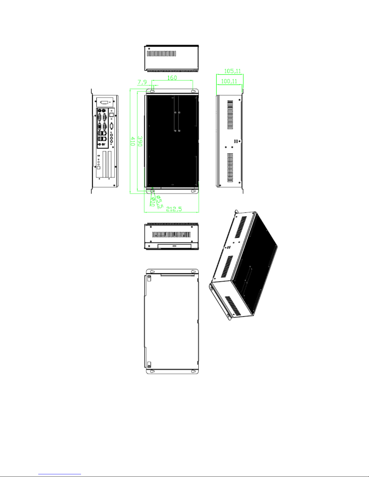
Dimensions:
410(W) x 105.11(D) x 212.5 mm(H)
Power Supply:
DC 11~32V wide range power input with 60W AC universal power adapter
Environment
Operating temperature:
0~60℃ (32℉~140℉)
Storage temperature:
-20℃~ 80℃ (-68℉~176℉)
Relative humidity:
10~90% (non-condensing)
EX-92622A User Manual
8
1.4 Dimensions
Figure 1.3: Dimensions of the EX-92622A
EX-92622A User Manual
9
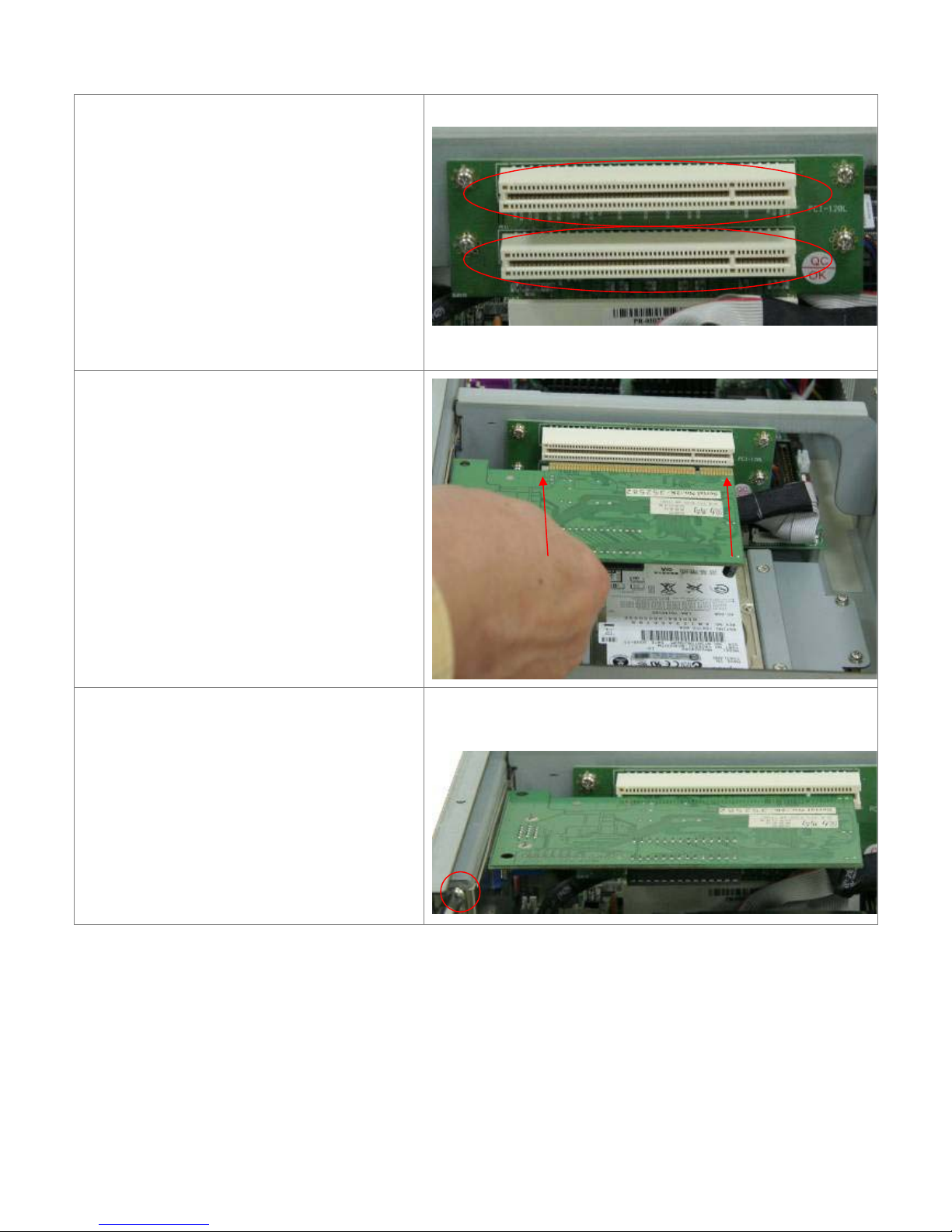
1.4 Installation of PCI Expansion Add on Cards
Shown in the picture are the two PCI
expansion slots for addons. The location of
the 2 x PCI expansion slot card is found by
the side of the rail. The slots face the CF
slot.
Now slide an addon into the slot of the PCI
as shown by the two arrows in the picture,
making sure the golden part of the card is
evenly aligned with the slot of the PCI.
Then carefully push the card deep into the
slot.
Now get the addon secured by tightening
the screw as circled in the picture.
CD-ROM
EX-92622A User Manual
10
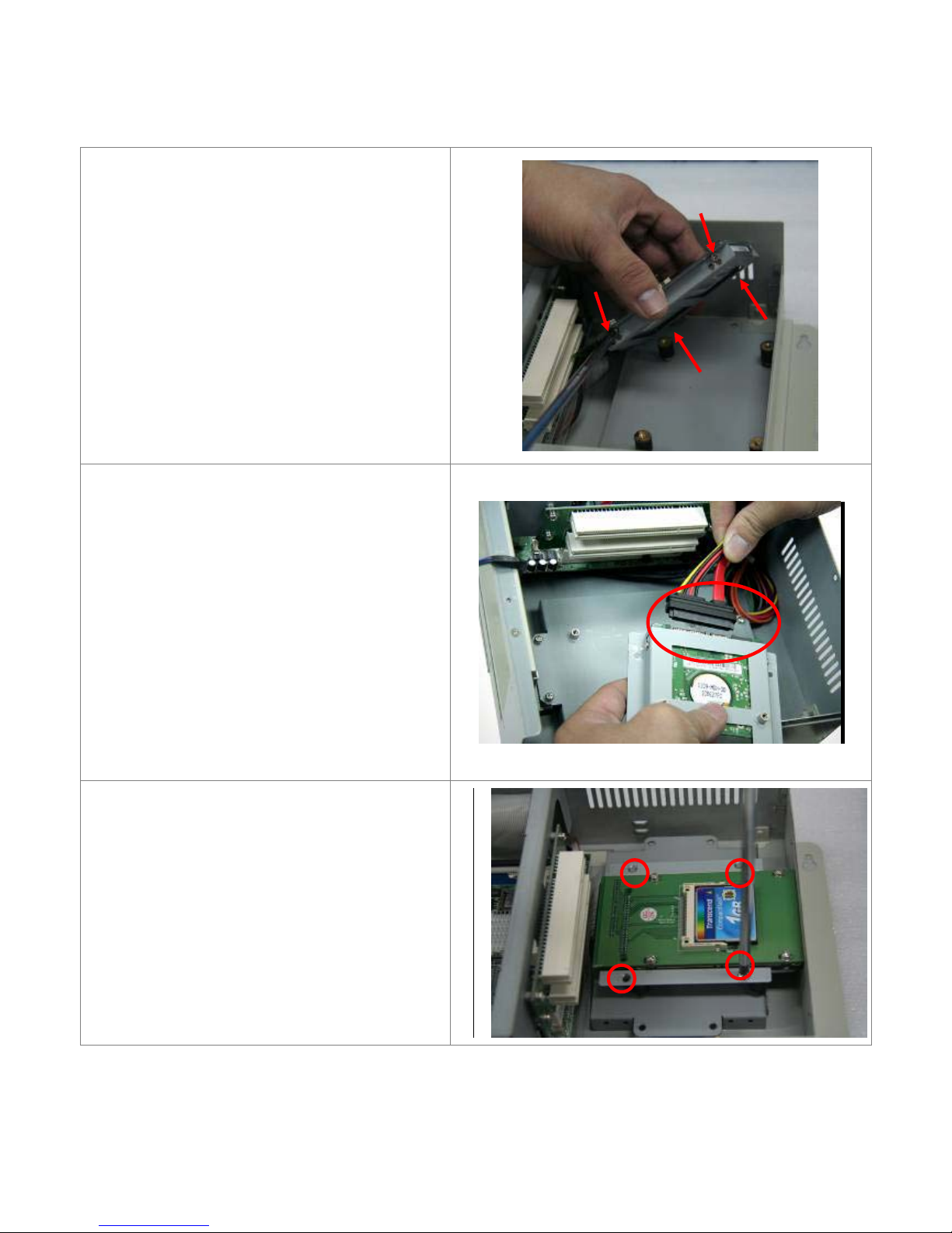
1.5 Installation of HDD
Step 1
Get the HDD screwed to the bracket with the
four screws as shown by the arrows in the
picture.
Step 2
Connect the cable to the HDD as shown in the
picture, making sure the red stripe of the cable
is rightly positioned.
Step 3
Get the four screws as circled tightened to
secure the HDD. As can be obviously seen, the
CF Card Board is screwed to the top of the
HDD.
EX-92622A User Manual
11
Step 4
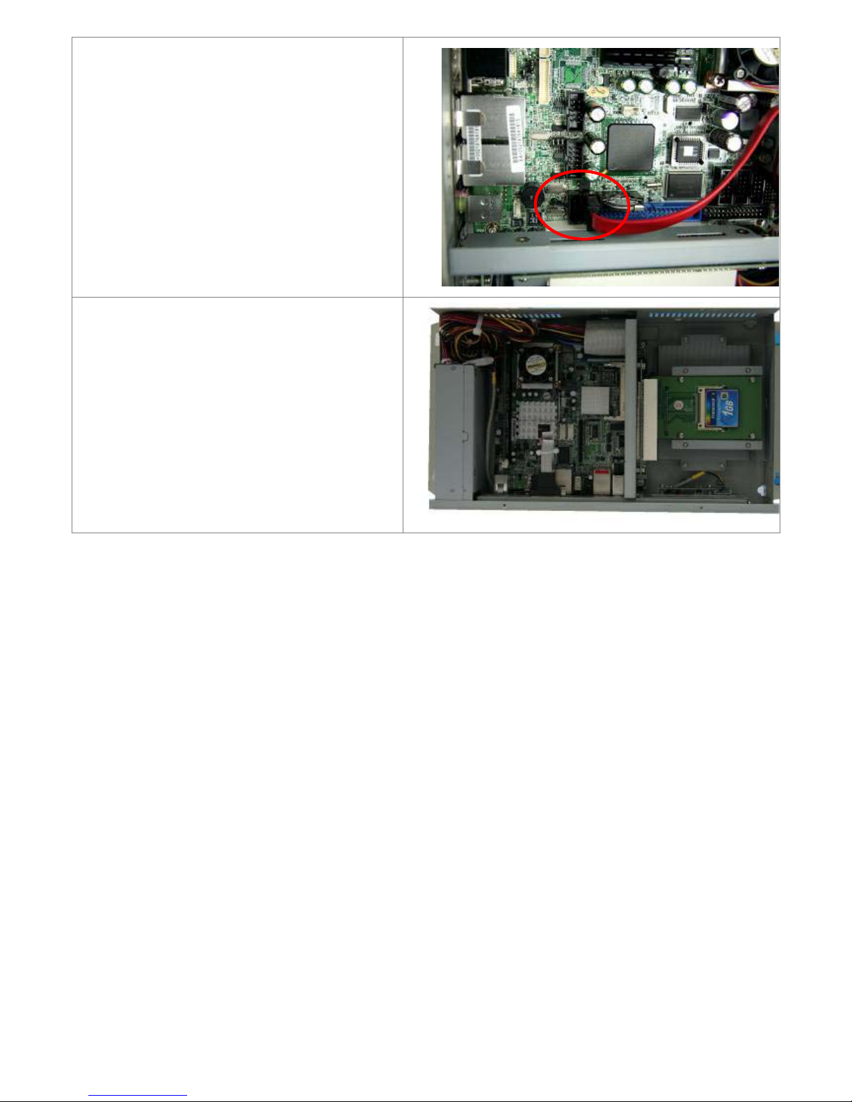
Connect the other end of the cable to the SATA
slot as shown in the picture.
Step 5
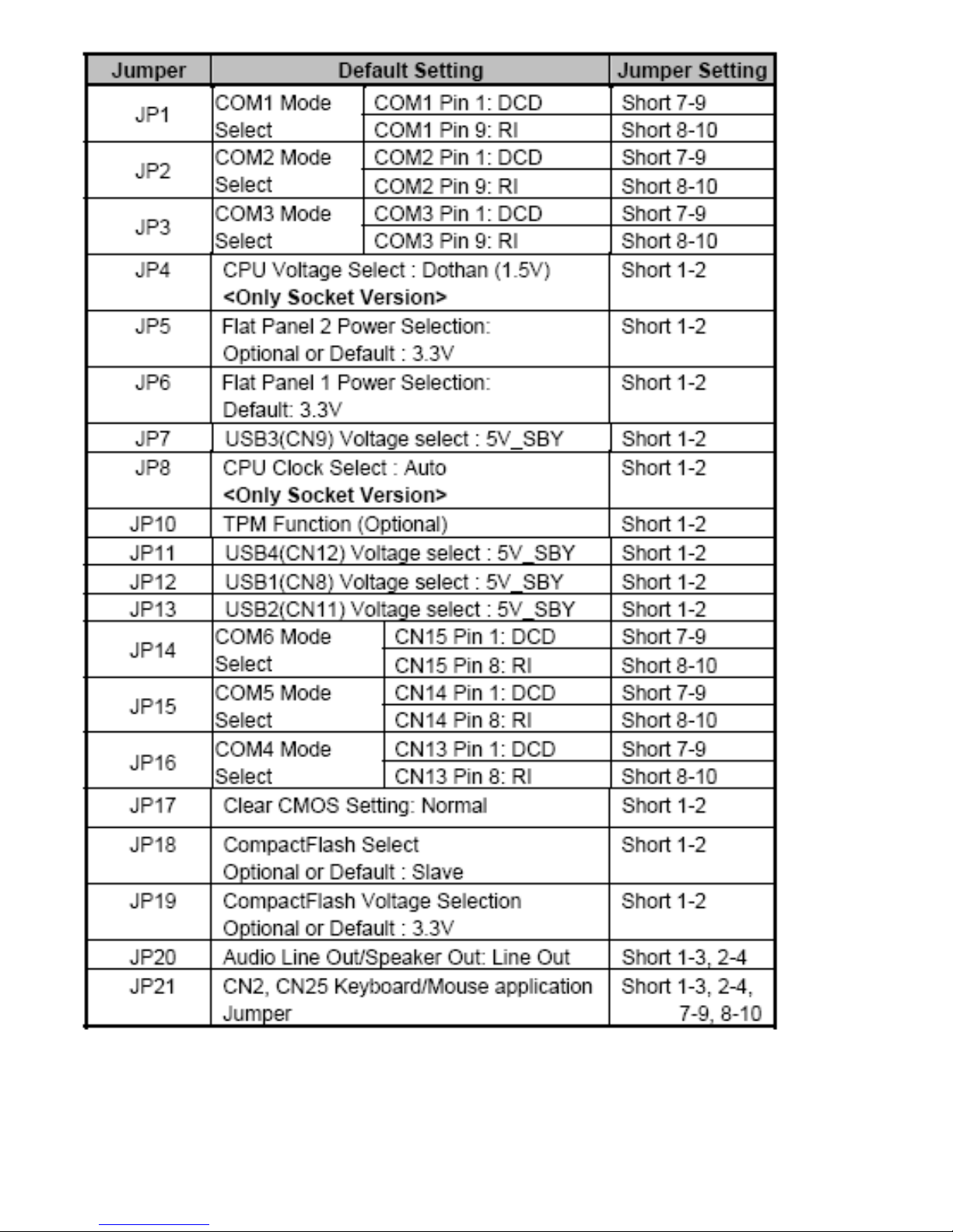
That’s how it should look after it has been
installed.

EX-92622A User Manual
12
Chapter 2____________________Hardware
2.1 Mainboard
Figure 2.1: Mainboard Overview

EX-92622A User Manual
13
2.2 Installing the CPU
The mainboard supports a Socket 479 processor socket for Intel Pentium M or Celeron M processors.
The processor socket comes with a screw to secure the processor. As shown in the left picture below,
loosen the screw first before inserting the processor. Place the processor into the socket by making
sure the notch on the corner of the CPU corresponds with the notch on the inside of the socket. Once
the processor slides into the socket, fasten the screw.
Figure 2.2: Installation of CPU
Note:
Make sure the heat sink and the top surface of the CPU are in total contact to avoid the
overheating problem that would cause your system to hang or be unstable.

EX-92622A User Manual
14
2.3 Installing the Memory
The Motherboard supports two DDR2 memory socket for a maximum total memory of 2GB in DDR2
memory type.
Installing and Removing Memory Modules
To install the DDR2 modules, locate the memory slot on the board and perform the following steps:
1. Hold the DDR2 module so that the key of the DDR2 module align with those on the memory slot.
2. Gently push the DDR2 module in an upright position until the clips of the slot close to hold the DDR2
module in place when the DDR2 module touches the bottom of the slot.
3. To remove the DDR2 module, press the clips with both hands.
Figure 2.3: Installation of Memory Module

EX-92622A User Manual
15
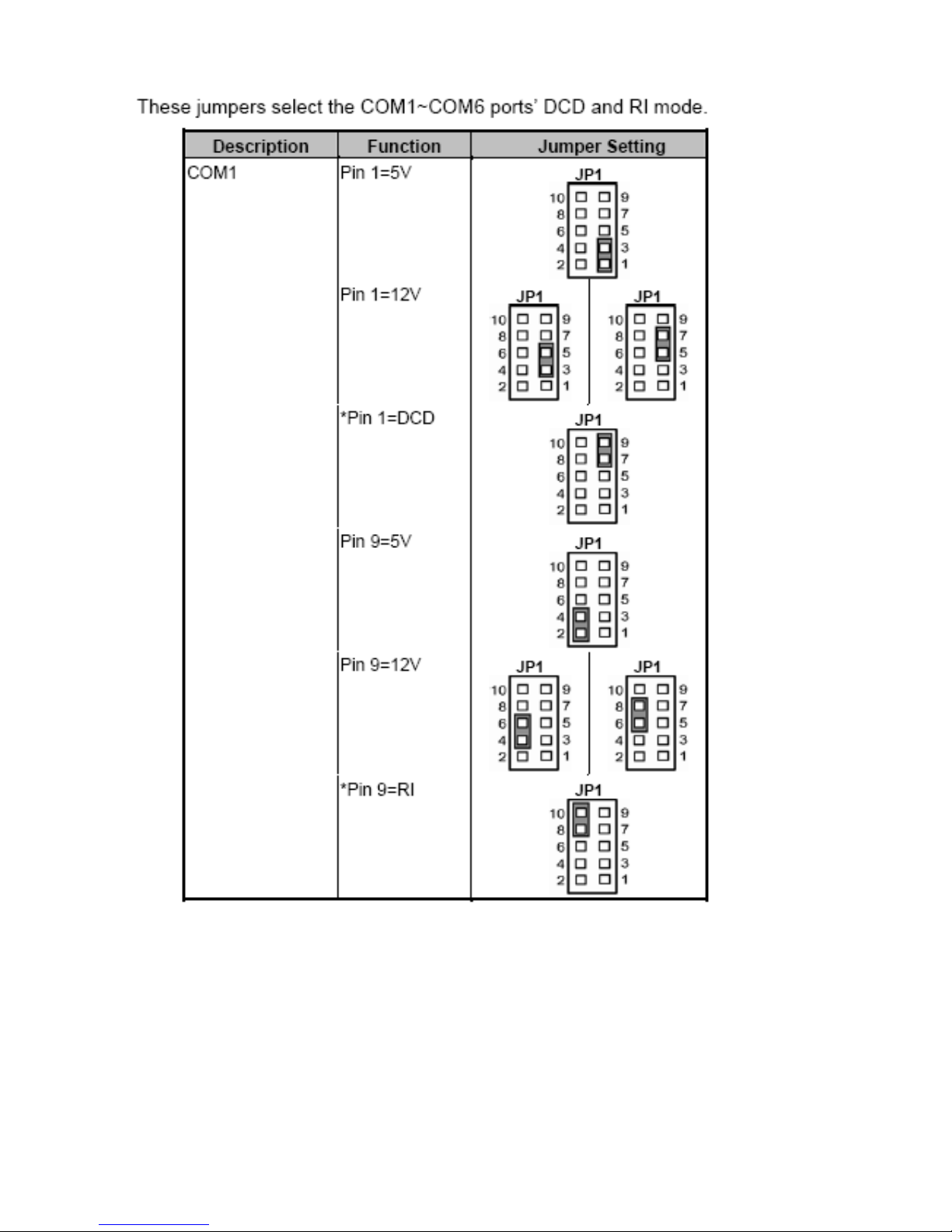
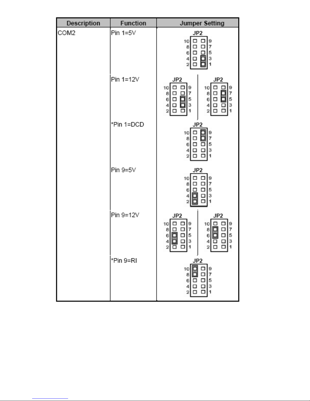
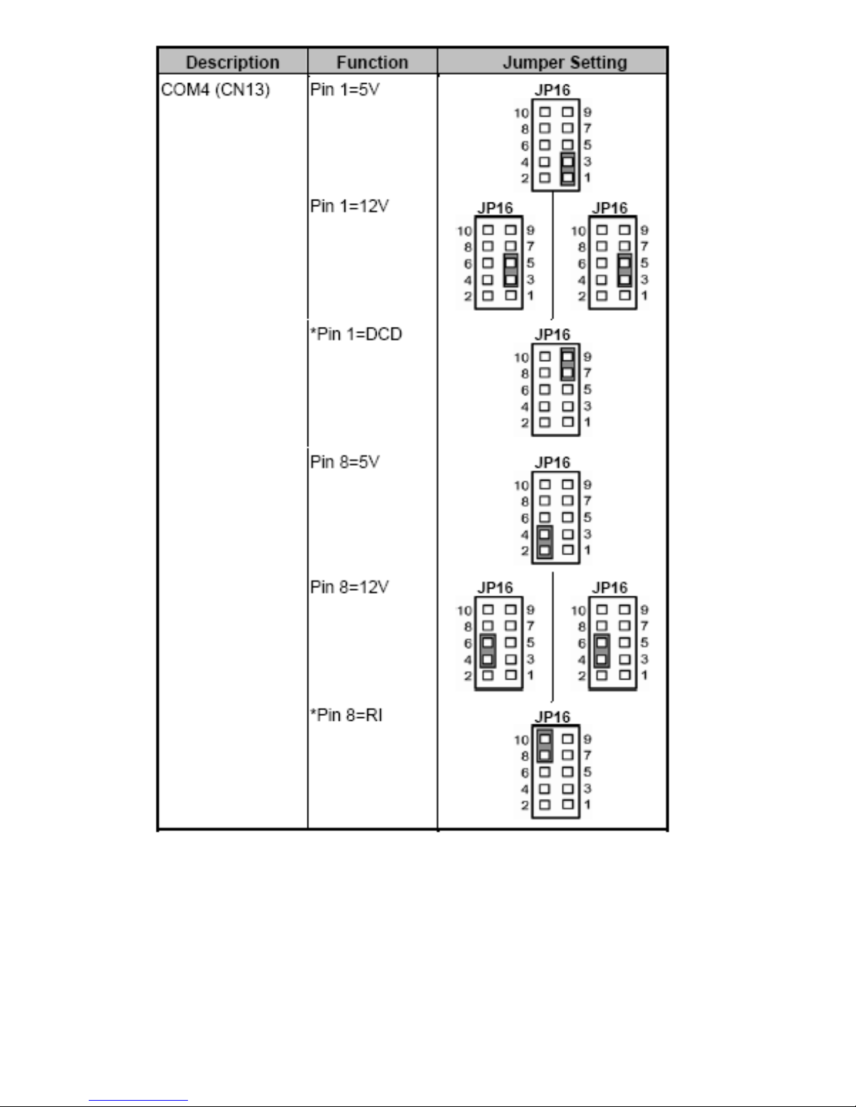
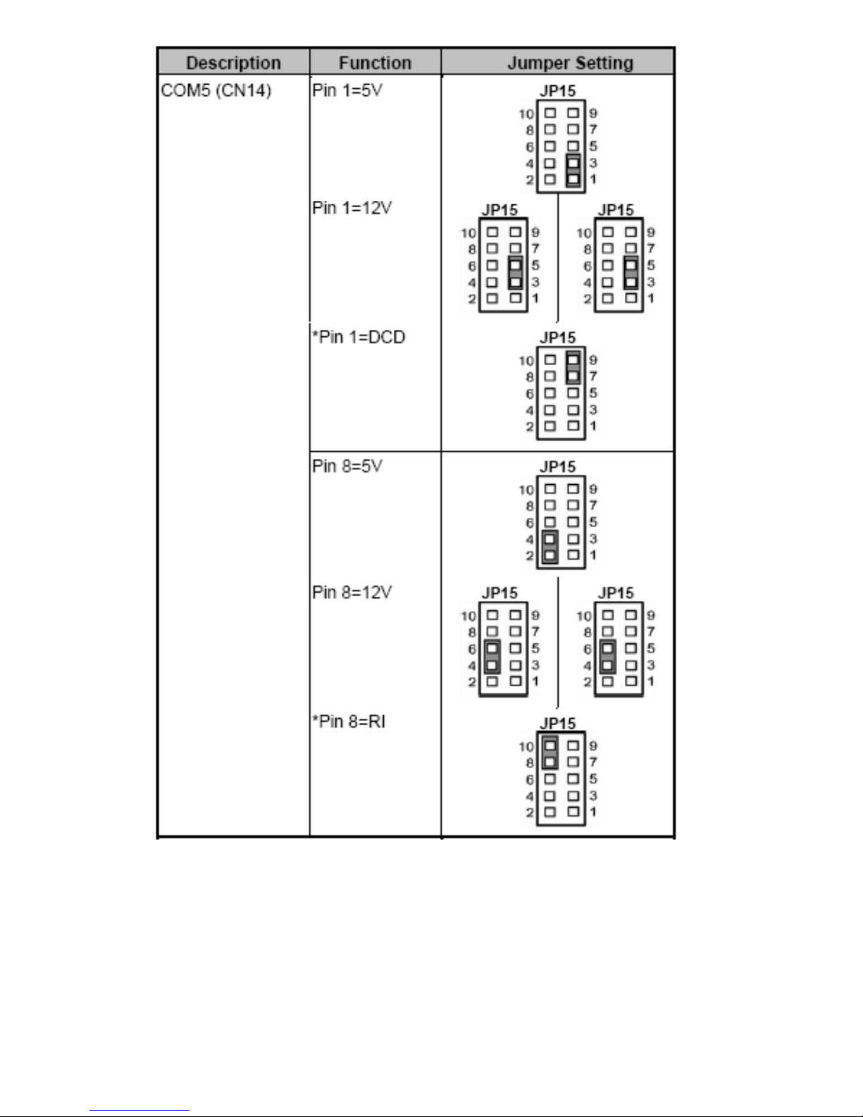
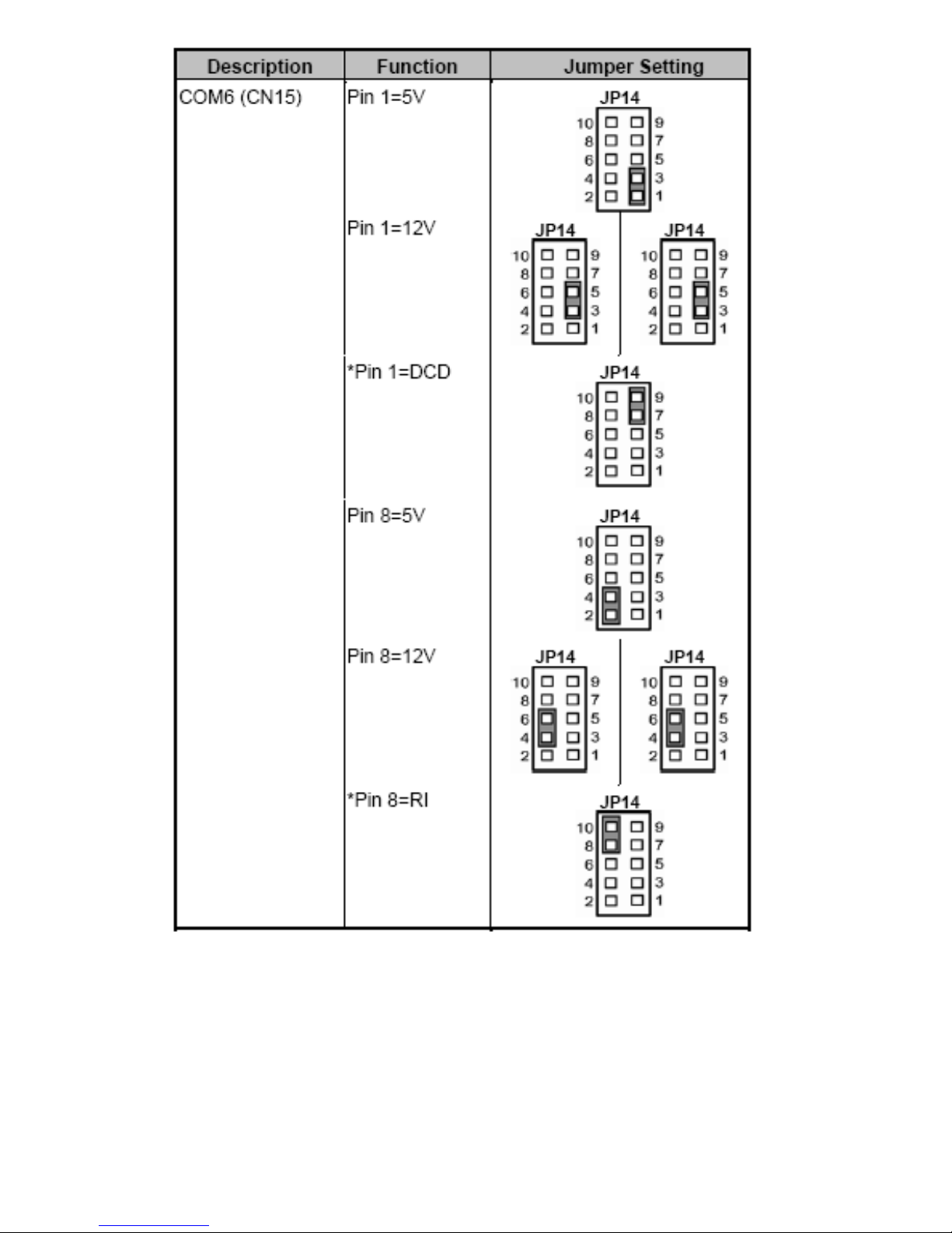
2.4 Installing the Jumpers
Jumpers are used on the mainboards to select various settings and features according to your needs
and applications. The following lists the connectors on the mainboard and their respective function.
Figure 2.4: Location of Jumpers
EX-92622A User Manual
16
EX-92622A User Manual
17
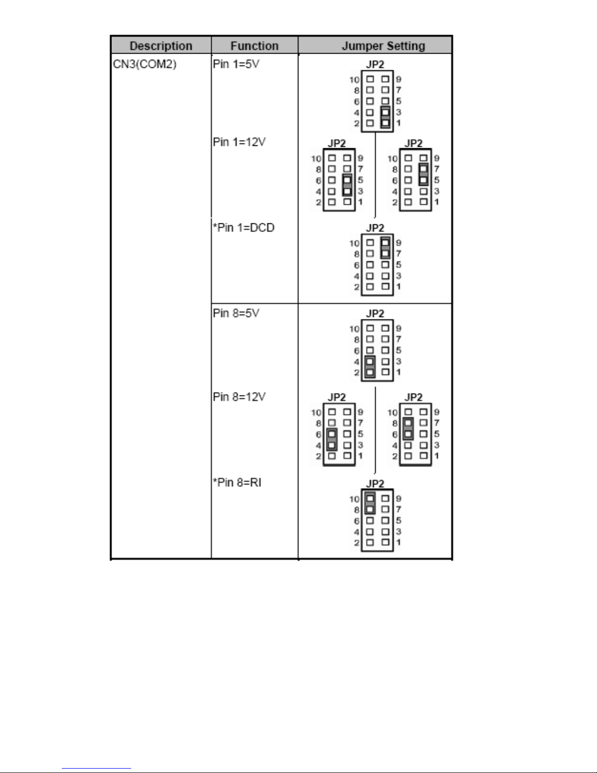
2.4.1 COM1~COM6 Mode Select for Type Jumpers
(JP1, JP2, JP3, JP16, JP15, JP14)
EX-92622A User Manual
18
EX-92622A User Manual
19

EX-92622A User Manual
20
EX-92622A User Manual
21
EX-92622A User Manual
22
EX-92622A User Manual
23

EX-92622A User Manual
24
2.4.2 CPU Analog voltage Select Jumper (JP4)
2.4.3 Flat Panel Connector Voltage Selection Jumper (JP5, JP6)
 Loading...