

Page 1

EX-91171 User Manual
1
EX-91171 Display Monitor
User Manual
Release Date Revision
Dec. 2005 V0.1
May. 2007 V0.2
®2005 All Rights Reserved. Published in Taiwan
Page 2

EX-91171 User Manual
2
Warning!___________________________________
This equipment generates, uses and can radiate radio frequency energy and if not installed and
used in accordance with the instructions manual, it may cause interference to radio communications.
It has been tested and found to comply with the limits for a Class A computing device pursuant to
FCC Rules, which are designed to provide reasonable protection against such interference when
operated in a commercial environment. Operation of this equipment in a residential area is likely
to cause interference in which case the user at his own expense will be required to take whatever
measures may be required to correct the interference.
Disclaimer
This information in this document is subject to change without notice.
Electric Shock Hazard – Do not operate the machine with its back cover removed. There are
dangerous high voltages inside.
Page 3

EX-91171 User Manual
3
Table of Contents______________________
Warning!…………………………………………………………………………….……..….2
Disclaimer………………………………………………………………….…………………2
Chapter 1 Getting Started
1.1 Features………………………………………………………….………….5
1.2 Specifications…………………………………………. ...……………...….5
1.3 Dimensions…………………………………...………………………….…7
1.4 Brief Description...................................................................................8
1.5 Display Mode……………………………………………………………….10
Chapter 2 OSD
2.1 Front Panel OSD Functions….………………………………….…..…...11
2.2 OSD Controls………………………………………………………………12
2.3 Main Menu…..……………………………………………………………..13
Chapter 3 Control Board
3.1 Introduction to PenMount Control Board………………………………..15
3.2 Features…………………………………………………………………….16
3.3 Electrical Specifications…………………………………………………...16
3.4 Installation of Control Board……………………………………………...17
Chapter 4 Installation
4.1 Windows 98/ME Driver Installation………………………………………18
4.2 Uninstall PenMount Windows 98/ME Driver…………………………….32
4.3 Windows 2000/XP Driver Installation…………………………………….33
4.4 Configuring PenMount Windows 2000/XP Driver………………………37
4.5 Uninstall PenMount Windows 2000/XP Driver………………………….47
Chapter 5 Software
5.1 Software Functions………………………………………………………..48
5.2 Software Function Descriptions……………………………………….…49
Page 4

EX-91171 User Manual
4
Appendix A: Board Description & Specifications………………….56
Appendix B: Controller IC Specifications………………………………58
Figures
Figure 1.1: Dimensions of EX-91171….……………………………………..7
Figure 1.2: I/O Functions of EX-91171……………………………………....7
Figure 1.3: Front View of EX-91171………………………………………….8
Figure 1.4: Rear View of EX-91171…..……………………………………...9
Figure 3.1: Bird Eye’s View of Control Board………………………………15
Figure 3.2: Mechanical Drawing of Control Board…………………………15
Figure A: Panelmounting……………………………………………………59
Figure B: VESA 100 mounting………………………………………….….60
Appendix
Panelmounting…..…………………………………………………………….59
VESA 100 mounting…………………………………………………………..60
Page 5

EX-91171 User Manual
5
Chapter 1_____________________________
1.1 Features
● 17” SXGA color TFT LCD monitor
● Heavy-duty steel chassis
● NEMA 4/IP65-compliant aluminum front panel
● OSD on the front panel
● Long backlight lifetime of 50,000 hours
● Panel or VESA 100 mount
● DVI, composite video and S-video input (optional)
● Power Input: 100~240V AC
● Resistive touch screen (optional)
1.2 Specifications
Display
● Display: 17” SXGA color TFT LCD monitor
● Maximum resolution: 1600 x 1200 with auto phase and auto position
● Maximum colors: 256K
● Dot size (mm): 0.264 x 0.264
● Luminance: 250 cd/m²
● Viewing angle: 150 degrees(H), 140 degrees(V)
● Backlight life: 50,000 hours
● Control: OSD on the front panel
● Touch screen: resistive (optional)
● Power Supply: Internal Universal AC/DC adapter
Mechanical
● Construction: heavy-duty steel chassis
● NEMA 4/IP65-certified front panel
● Mounting type: panel or VESA 100 mount
● Auto recognition of input signal
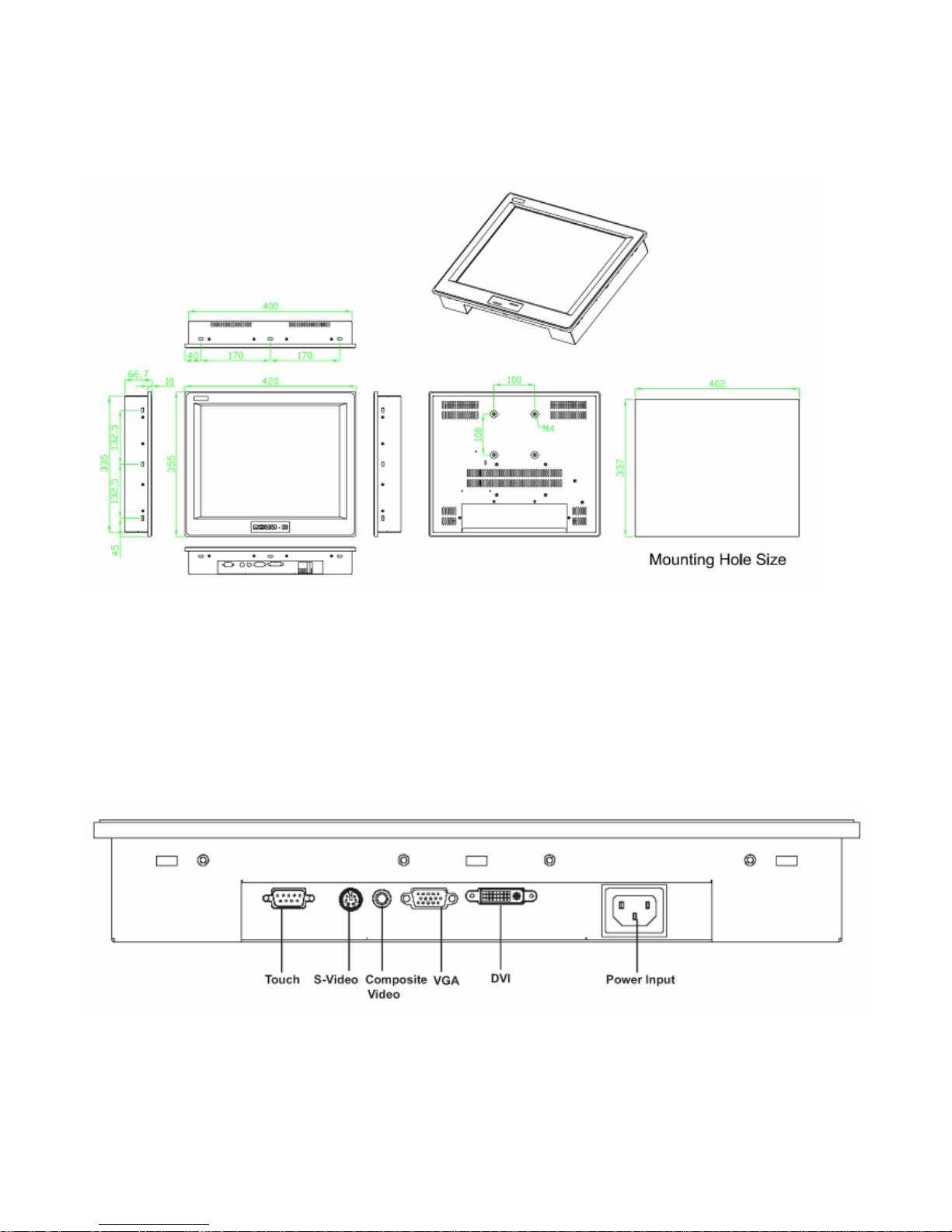
● Dimensions(WxHxD): 420 x 66.7 x 355mm (16.5” x 14” x 26”)
Page 6

EX-91171 User Manual
6
Environmental
● Operating temperature: 0 to 45℃ (32 to 113℉)
● Storage temperature: -20 to 60℃ (-4 to 140℉)
● Relative humidity: 10 to 95% @40℃, non-condensing
● Vibration: 1G peak, 10~150Hz
● Shock: 10G peak acceleration (11 msec.duration)
● Certification: CE, FCC Class A
Page 7
EX-91171 User Manual
7
1.3 Dimensions
Figure 1.1: Dimensions of the EX-91171
Figure 1.2: I/O Functions of the EX-91171
Page 8
EX-91171 User Manual
8
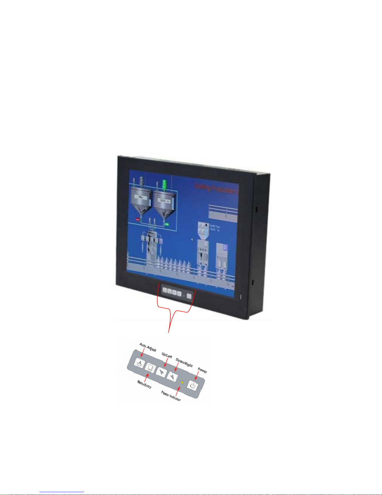
1.4 Brief Description of the EX-91171
The EX-91171 is a 17" SXGA color TFT LCD monitor that comes with a dot size of 0.264 x 0.264mm,
viewing angle of 150 (H) degrees and 140 (V) degrees, and more outstanding features, thus giving
you the best in monitoring and control applications.
The front panel of the display monitor is sealed with gasket for NEMA 4/IP 65 rating when it is
panel-mounted in a NEMA rated cabinet or enclosure. It can also be VESA 100-mounted. It is optional
to be equipped with a resistive touch screen.
Figure 1.3: Front View of the EX-91171
Page 9
EX-91171 User Manual
9
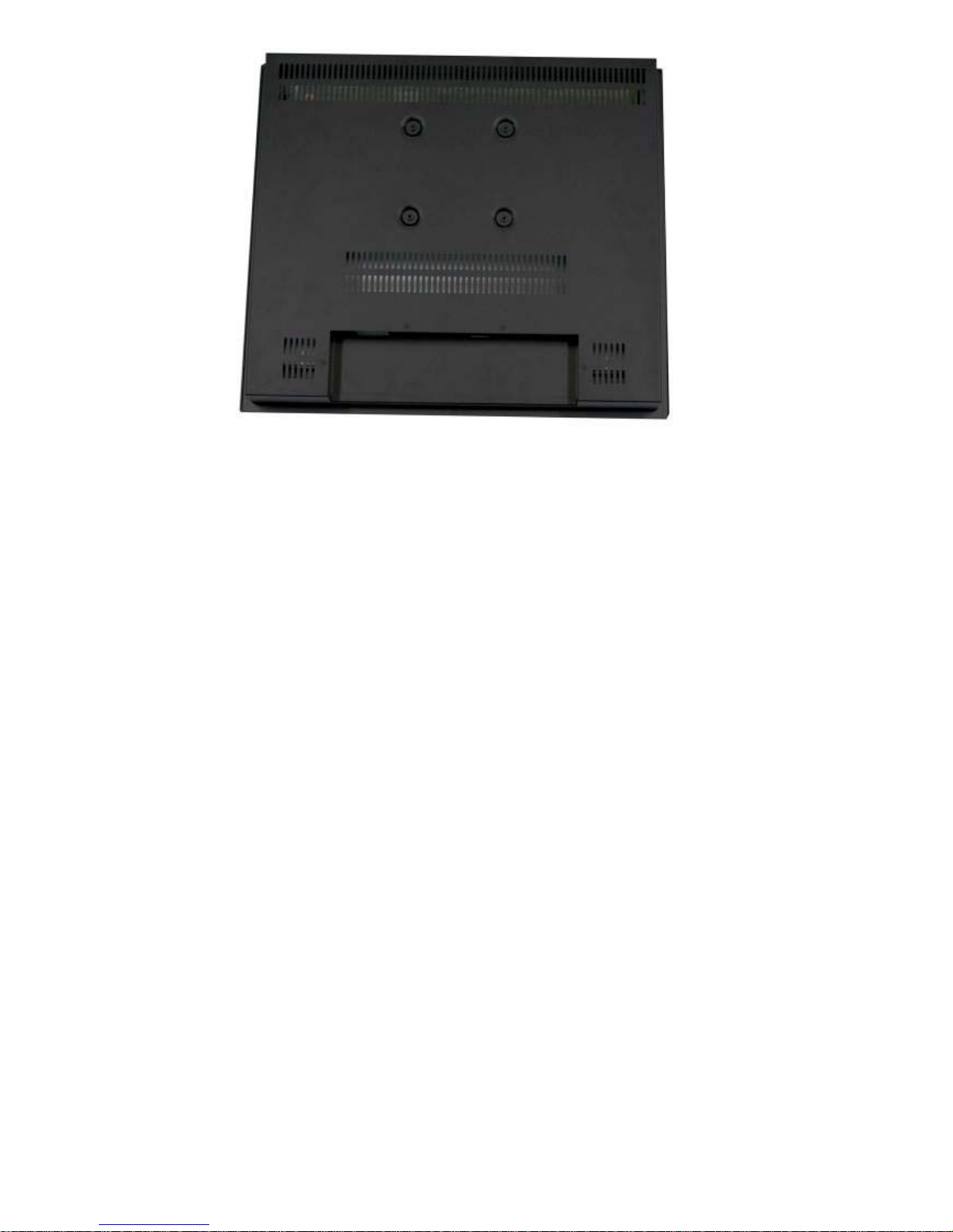
`Figure 1.4: Rear View of EX-91171
Page 10
EX-91171 User Manual
10
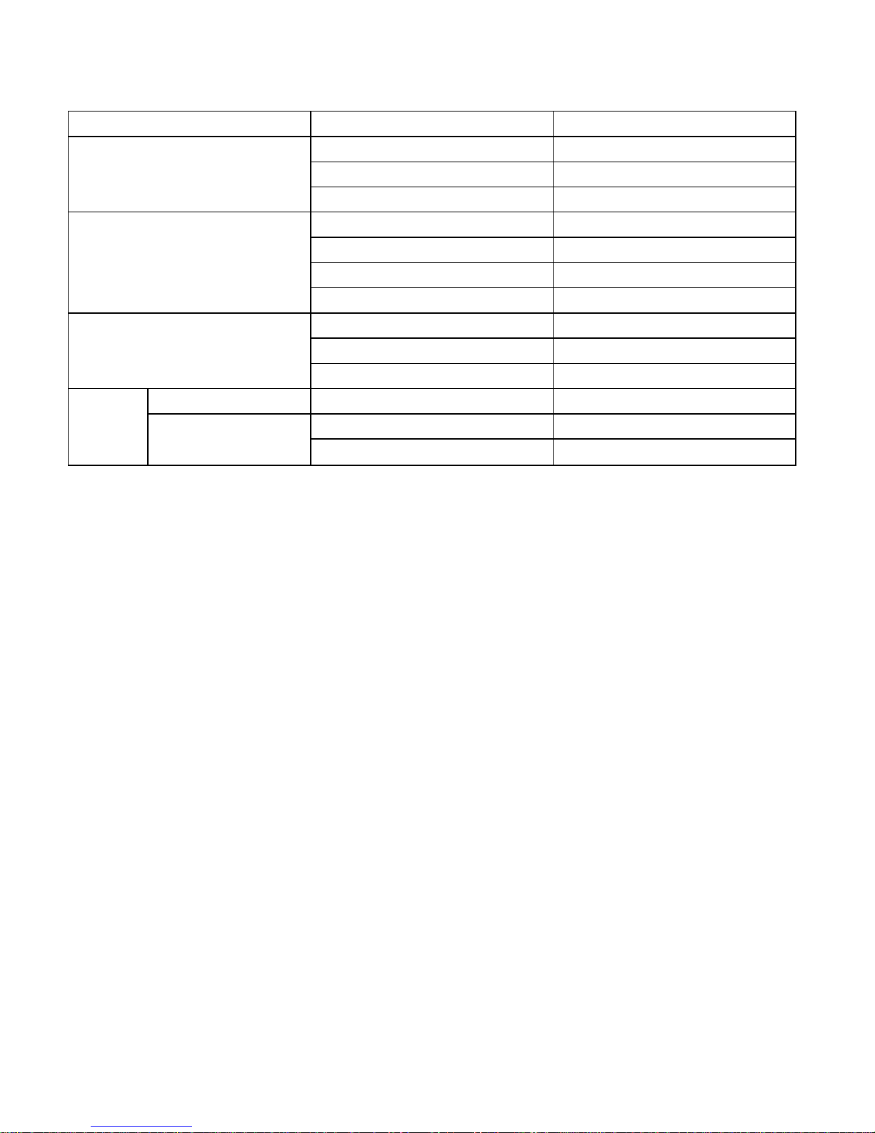
1.5 Display Mode
Display Mode Hori. Sync (KHz) Vert. Sync. (Hz)
31 60
VGA 640 x 480 38 72
38 75
35 56
SVGA 800 x 600 38 60
48 72
47 75
48 60
XGA 1024 x 768 56 70
60 75
1152 x 864 68 75
64 60
SXGA
1280 x 1024
80 75
Page 11
EX-91171 User Manual
11
Chapter 2_____________________________
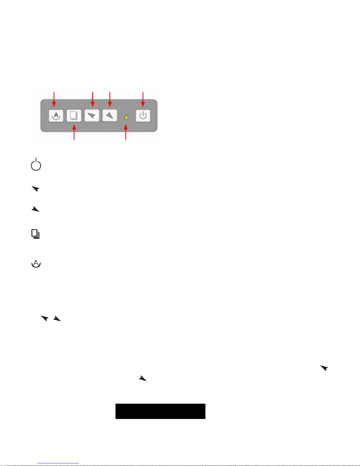
2.1 Front Panel OSD Functions
Auto Adjust Up/Left Down/Right Power
Menu/Entry Power Indicator
Power switch: To turn ON or OFF the power
Shift the icon to the right side or shift it up
Shift the icon to the left side or shift it down
Menu: To enter OSD menu for related icon and item.
Auto Button: One-touch auto adjustment
1.) Getting into Burn-in Mode
Before setting into a burn-in mode, first disconnect the AC power cord. Then press (don’t let them go)
the
buttons until the AC power cord is connected and the “RGB” appears on the top left corner
of your screen. Now it can be put into the burn-in mode for changing colors.
2.) Getting Out of Burn-in Mode
Before getting out of the burn-in mode, please first disconnect the AC power cord. Then press the
button (If not workable, press the
button and don’t let them go) until the AC power cord is
connected. Please don’t let your fingers go until the AC power cord is connected again and the
wording of “RGB” appears on the top left corner of your screen, and wait for 3 seconds. Under the
non-signal entry situation, if is seen, exit is thus successfully made.
Cable Not Connected
Page 12
EX-91171 User Manual
12
2.2 OSD Controls
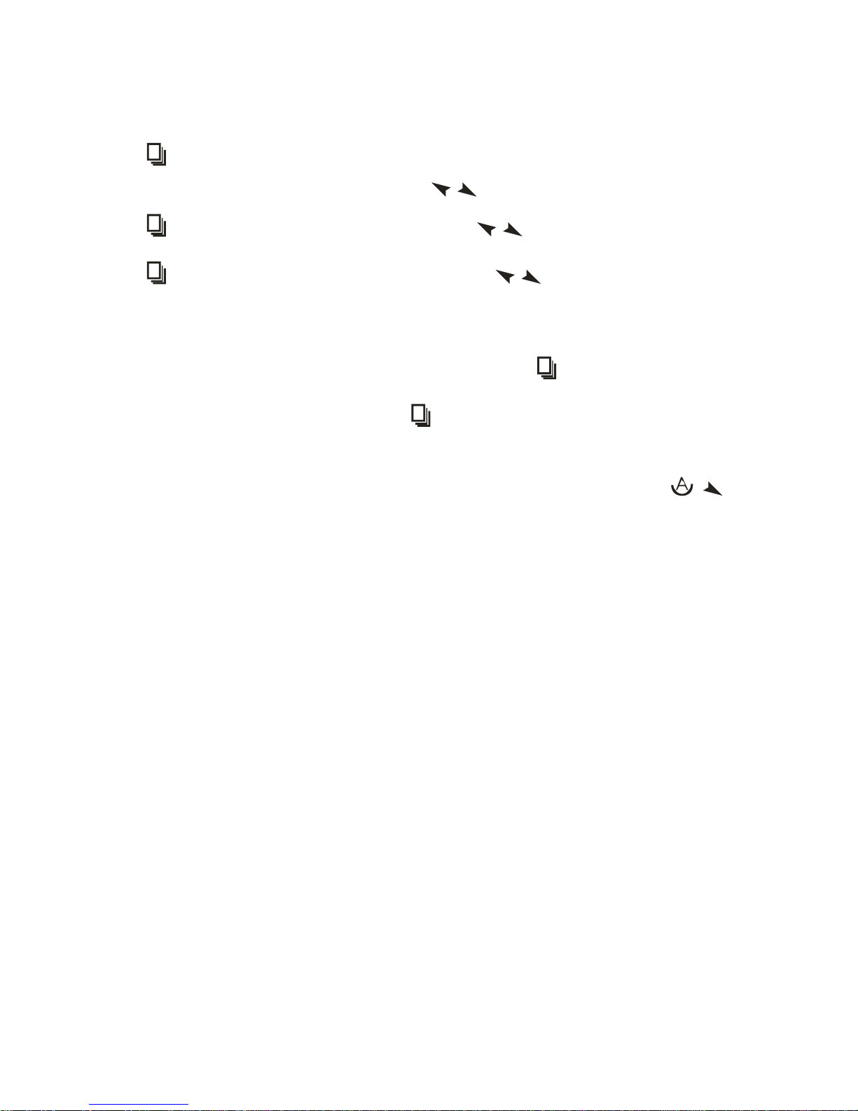
To make any adjustment, select the following:
1. Press
(Menu) to show the OSD menu or disable the OSD menu.
2. Select the icon that you wish to adjust with the ( / or +/-) key in the menu.
3. Press (Menu) and then choose the item with the ( / or +/-) key.
4. Press (Menu) and then adjust the quality with the ( / or +/-) key.
1.) If the “RGB” is still on the top left corner of the screen, press to enter “Miscellaneous” and
choose “Reset”, and then Yes, and press . When the screen goes black, disconnect power
and repeat the above steps.
2.) If the “RGB” is not found, disconnect the AC power cord first. Then press the buttons
(don’t let them go) until the AC power cord is connected, and wait for 2 to 3 seconds. When
“RGB” appears, repeat the above steps.
3.) Functions of OSD Keys
Page 13
EX-91171 User Manual
13
2.3 Main Menu
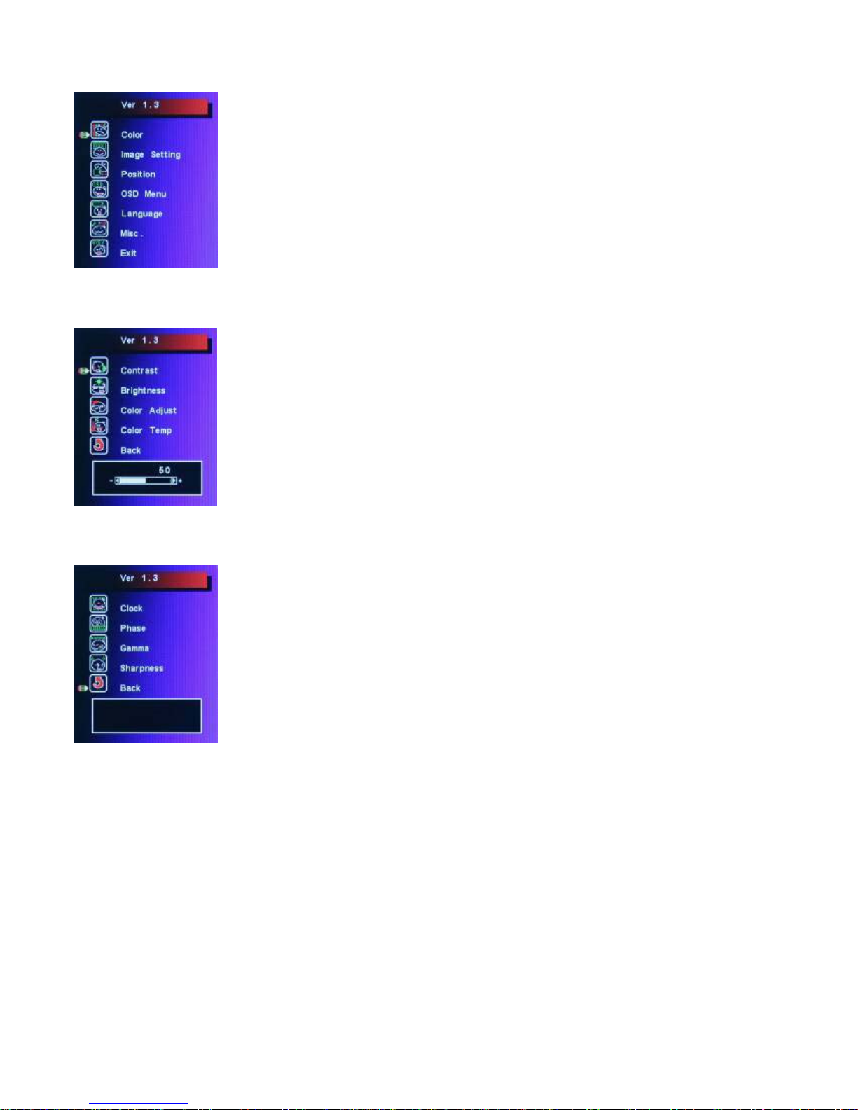
In the Main menu, there are the following items:
z Color
z Image Setting
z Position
z OSD Menu
z Language
z Misc
z Exit
For Color, check out the following:
z Contrast
z Brightness
z Color Adjust
z Color Temp
z Back
For Image setting, check out the following:
z Clock
z Phase
z Gamma
z Sharpness
z Back
Page 14
EX-91171 User Manual
14
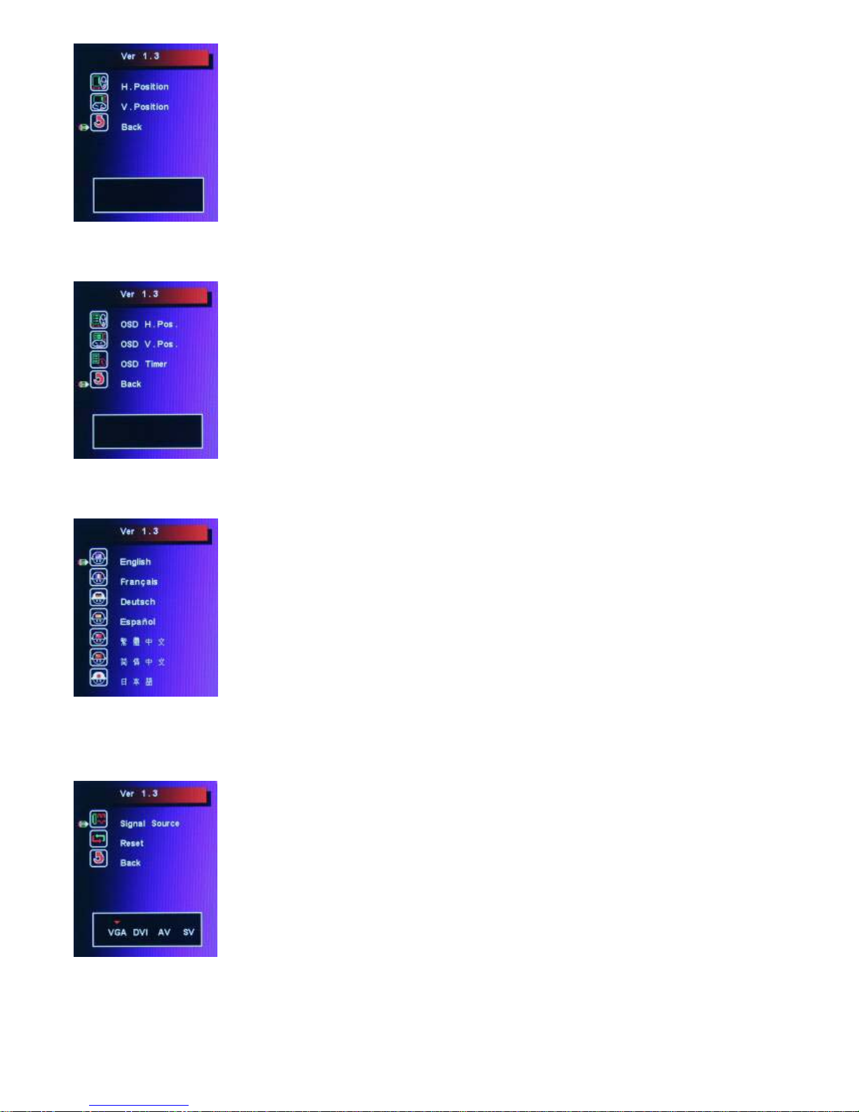
In the Position, there are the following:
z H. Position
z V. Position
z Back
In the OSD menu, there are:
z OSD H. Pos.
z OSD V. Pos.
z OSD Timer
z Back
In the Language menu, there are:
z English
z Frances
z Germany
z Spanish
z Traditional Chinese
z Simplified Chinese
z Japanese
In the Misc menu, there are:
z Signal Source
Select VGA: Analogue VGA Input
Select DVI: Digital DVI-D Input
Select AV: Composite Video Input
Select SV: S-Video Video Input
z Reset
z Back
Page 15
EX-91171 User Manual
15
Chapter 3_____________________________
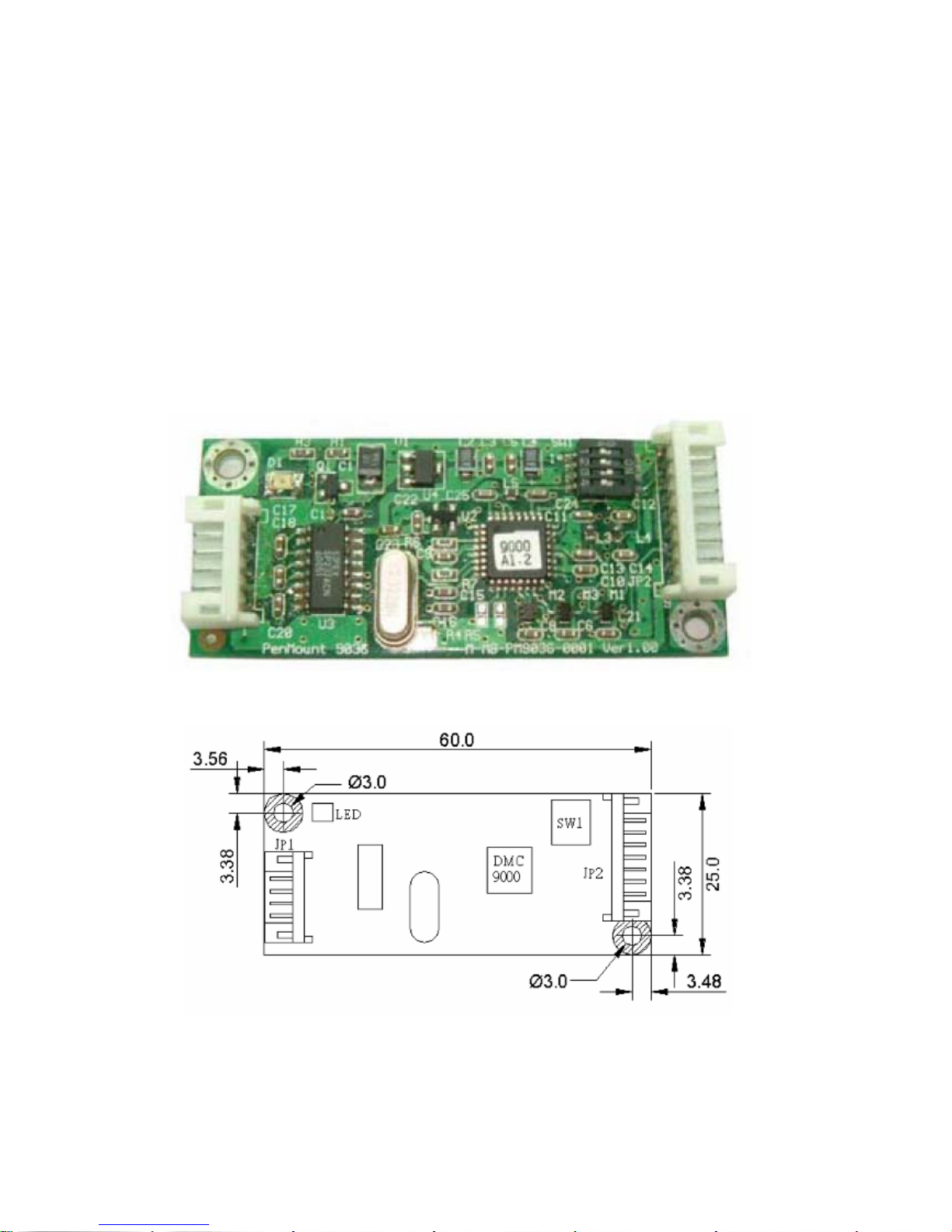
3.1 Introduction to the PenMount 9036 Controller Board
The PenMount 9036 control board is configured for use with the RS-232 interface. It connects to the
touch screen, power supply and computer system’s RS-232 port, and supports 4-, 5- and 8-wire touch
screens. The control board has some advanced functions, such as PnP and non-PnP mode adjustable
baud rate, thus making easy for customers to select different touch screens without changing the
control board. The size of the board is 25 by 60mm, and it has two connectors and one dipswitch
on-board.
Figure 3.1: Bird’s Eye View of PenMount 9036
Figure 3.2: Mechanical Drawing of PenMount 9036
Page 16

EX-91171 User Manual
16
3.2 Features
z RS-232 interface
z Touch controller is DMC9000
z Design for the best touch performance and easy configuration
z PnP or Non-PnP mode selectable
z Design for best cost arrangement
z Supporting 2048x2048 pen device resolution
z 19200 or 9600 baud rate transmission selectable
z Upgraded noise handling mechanism (3 level scheme)
z Fixed and high-speed sampling rate
z 4-, 5- and 8-wire touch screen supported
z Touch screen cable, RS-232 with power cable connectors onboard
z 5V to 12V power input
z Circuit protection for input voltage
z Touch-activated LED indicator onboard
3.3 Electrical Specifications
Touch Screen:
4-, 5- and 8-wire analog resistive type
Touch Screen Controller:
DMC9000
Communications:
RS-232
Baud Rate:
19200 and 9600 baud rate selection
Resolution:
1024x1024 (10-bit A/D converter inside)
Power Input:
5V ~ 12V DC
Power Consumption:
12V: 24mA+ i where (i=v/touch screen sheet R)
5V: 20mA+ i where (i=v/touch screen sheet R)
Page 17
EX-91171 User Manual
17
Board Size:
6.0 x 2.5cm
Portrait:
Support 90°to 279°screen rotation
Static Protection:
ESD device (optional)
3.4 Installation of the 9036 Controller Board
Follow the steps below to install the 9036 control board:
1. Power down your computer and display, and open your display or system case. Find space on your
system and attach the control board to your system with screws. The control board has industry
standard 3φ screw holes.
2. Find the white 6-pin right-angle connector (on the left in the image above [see Figure 3.1]). The
power cable is pin 1 and pin 2. Solder the power and ground wire to the system. The RS-232 cable
is for pins 3 to 6. Attach the RS-232 cable’s D-sub connector to a COM port at the back of the
computer.
3. Find the white 9-pin right-angle connector (on the right in the image above [see Figure 3.1]). Attach
the female end of the touch screen cable to this connector. If you attach the cable of a 4-/5-/8-wire
touch screen to pins 1~5/1~6/1~9, attach the male end of the cable to the touch screen tail.
4. Mount your touch screen to the display.
5. Find the onboard DIP switch (on the upper right of the image above [see Figure 3.1]). This switch
selects baud rate, PnP or non-PnP mode, and touch screen type. Set the DIP switch to configure
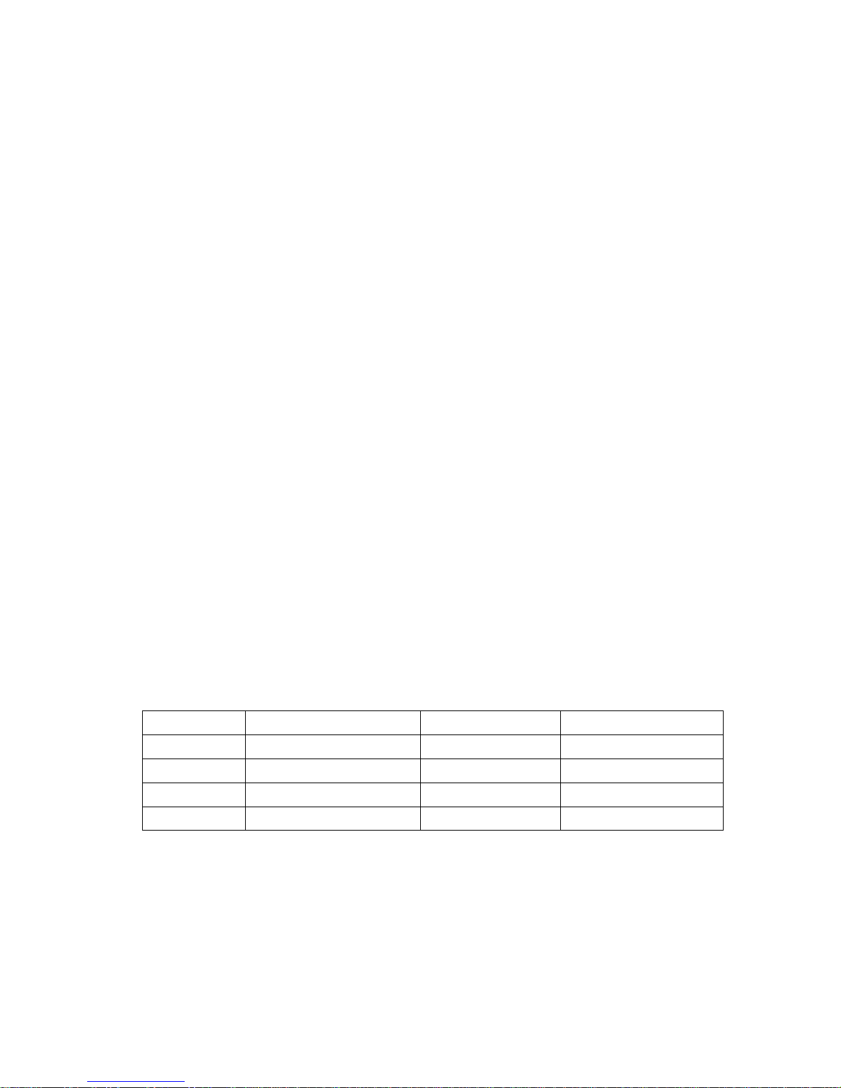
your control board according to the definitions and settings of the table below:
Switch Definition ON OFF
S1 Baud Rate Adjustment 9600 19200
S2 PnP enable or disable Disable Enable
S3 Touch screen type 5-wire 4-, 8-wire
S4 Touch screen type 4-, 8-wire 5-wire
6. Turn on power to the computer and the display.
7. Install the software drivers and utilities and calibrate the touch screen.
Page 18
EX-91171 User Manual
18
Chapter 4_____________________________
4.1 Windows 98/ME Driver Installation for 9036 Controller Board
Before installing the Windows 98/ME driver software, you must have the Windows
98/ME system installed and running on your computer. You must also have the 9036
PenMount Serial Interface controller board installed. Contents of the PenMount
Windows 98/ME driver folder are listed below:
SETUP.EXE
DMC9000.INF
DMC9000.VXD
If you have an older version of the PenMount Windows 98/ME driver installed in your
system, please remove it first. Follow the steps below to install the PenMount Windows
98/Me driver.
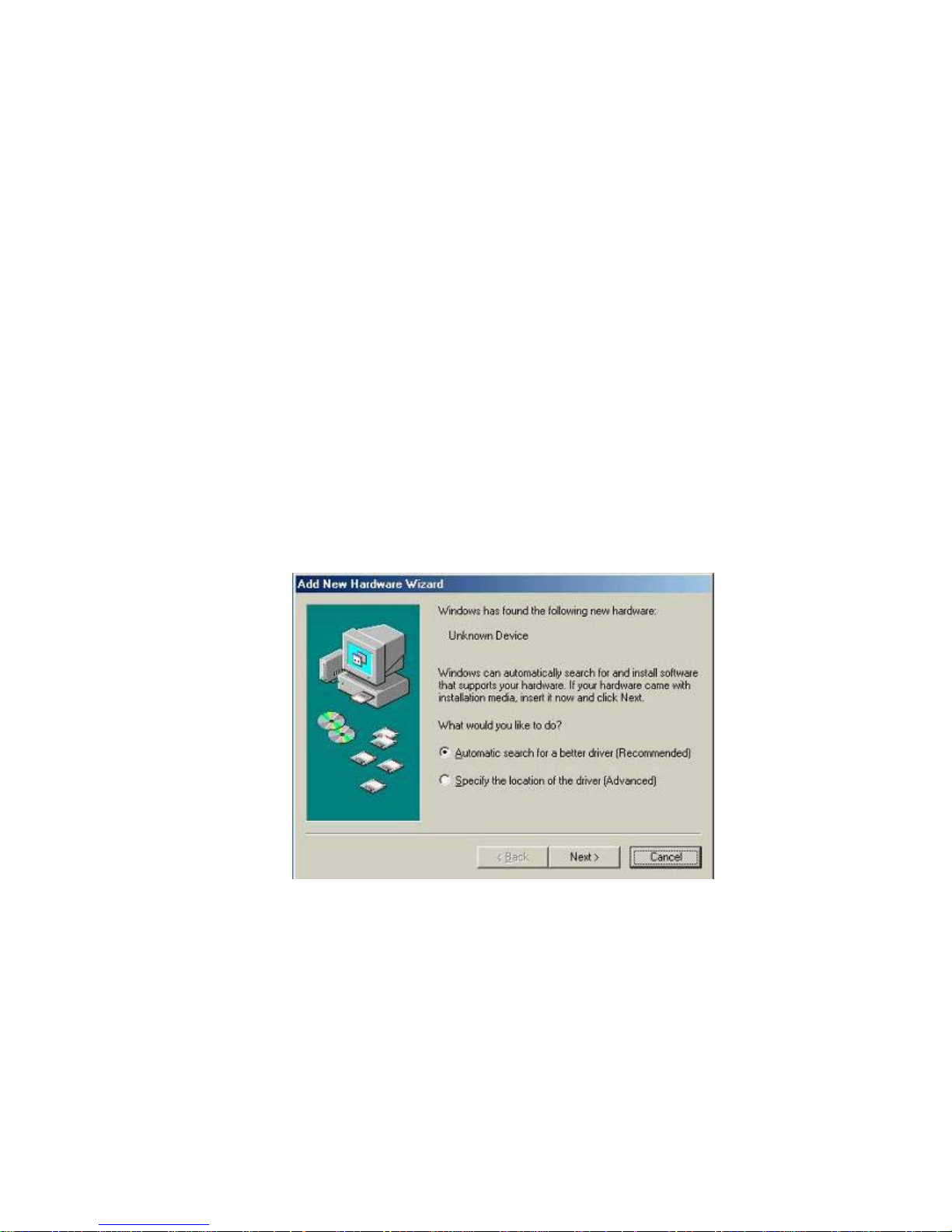
1. When the system first detects the controller board, a screen appears that shows
“Unknown Device.” Do not use this hardware wizard. Press Cancel.
Page 19
EX-91171 User Manual
19
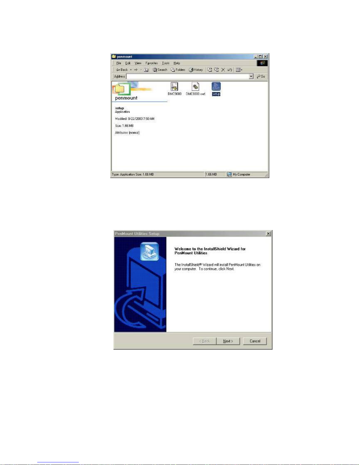
2. Install the PenMount Windows 98/ME driver onto your system from the CD-ROM:
3. A welcome message for the PenMount utilities setup program appears. Select “Next”.
Page 20
EX-91171 User Manual
20
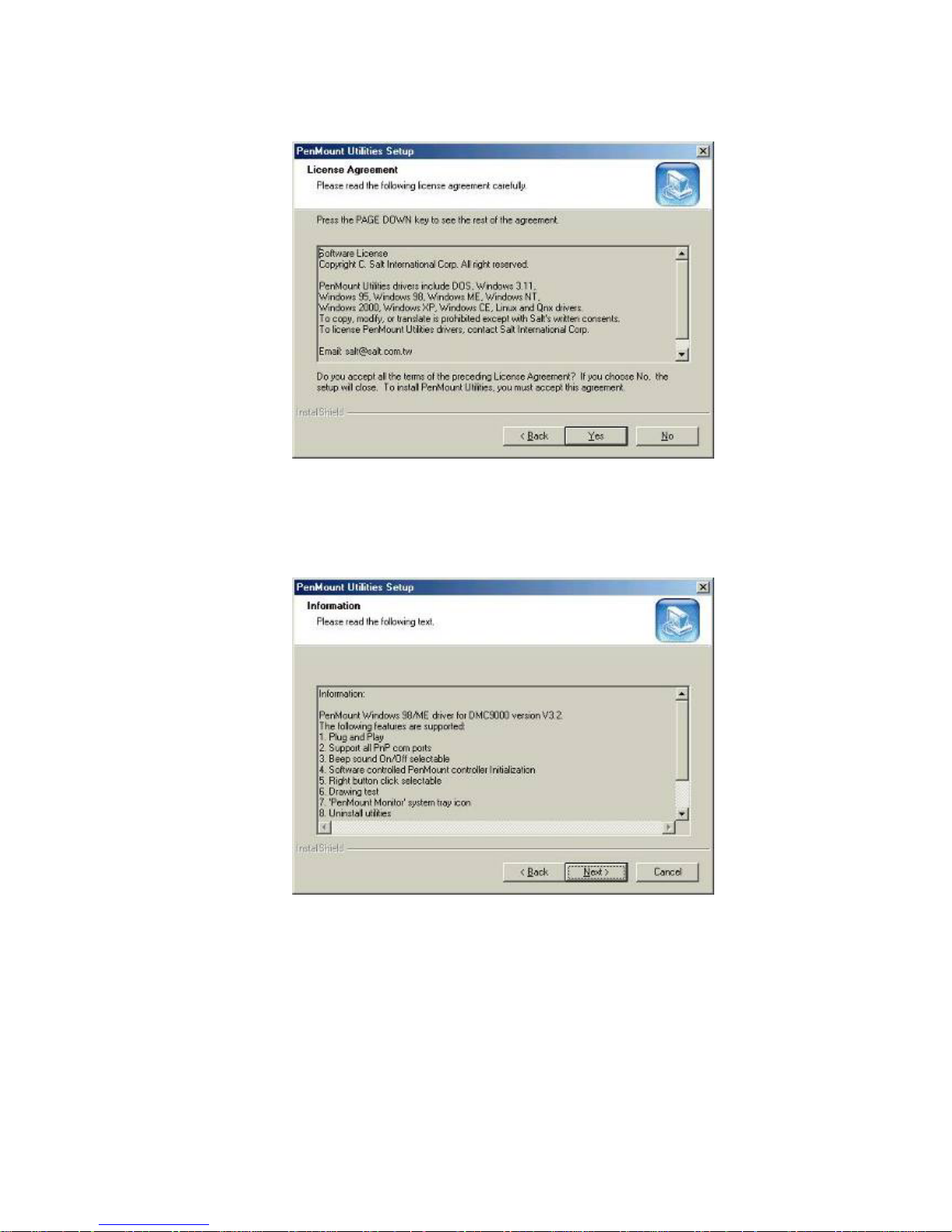
4. The Software License Agreement screen appears. Select "Yes".
5. The Information screen appears. Select "Next".
Page 21
EX-91171 User Manual
21
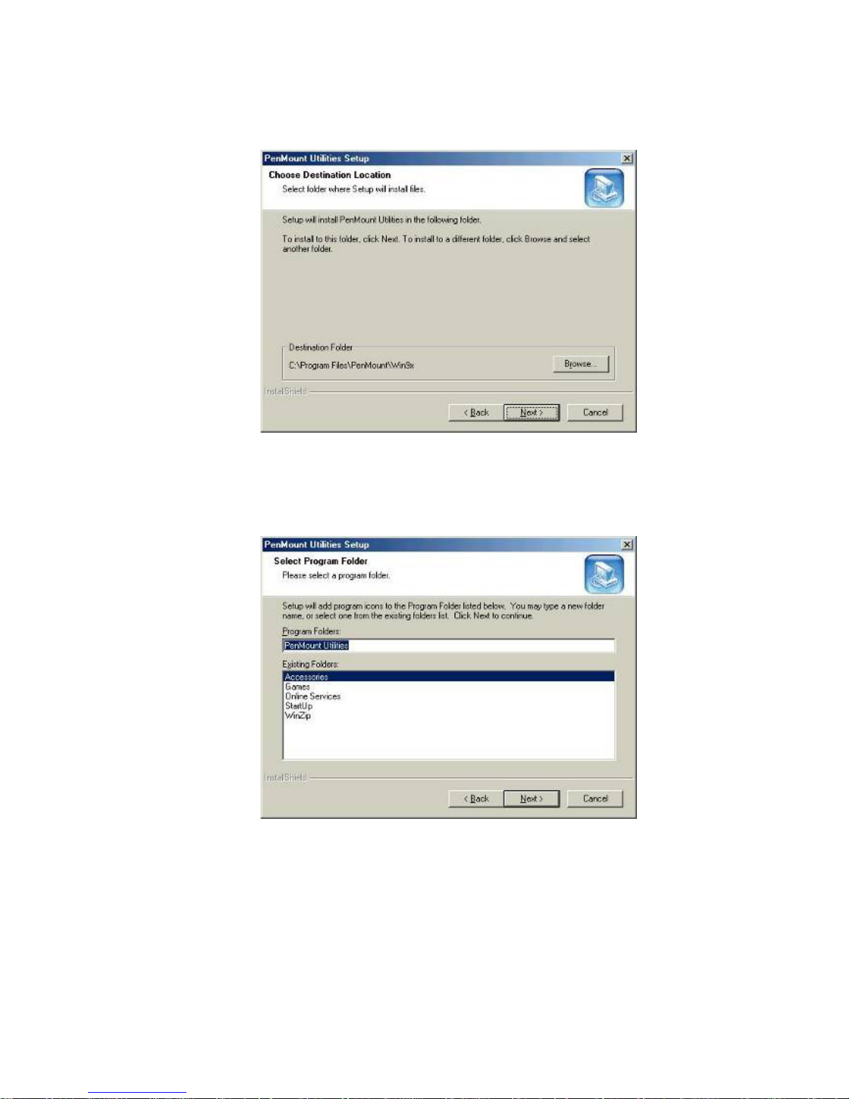
6. The Choose Destination Location screen appears. This installs PenMount Utilities in
the folder: C:\Program Files\PenMount\Win9x. Select "Next” or modify the folder
name to the one you would like to use.
7. The Select Program Folder screen appears. The default is "PenMount Utilities".
Select "Next” or change it.
Page 22
EX-91171 User Manual
22
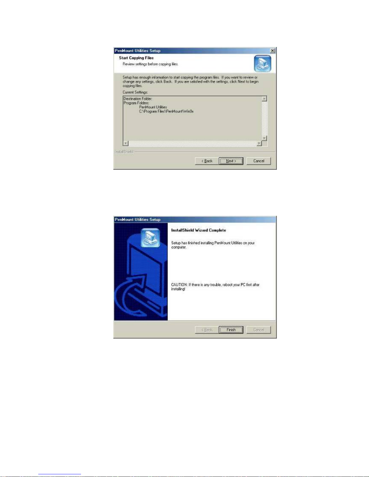
8. The Start Copying Files screen appears. Select "Next" to copy files to the system.
9. The Setup Complete screen appears. Select "Finish".
Page 23
EX-91171 User Manual
23
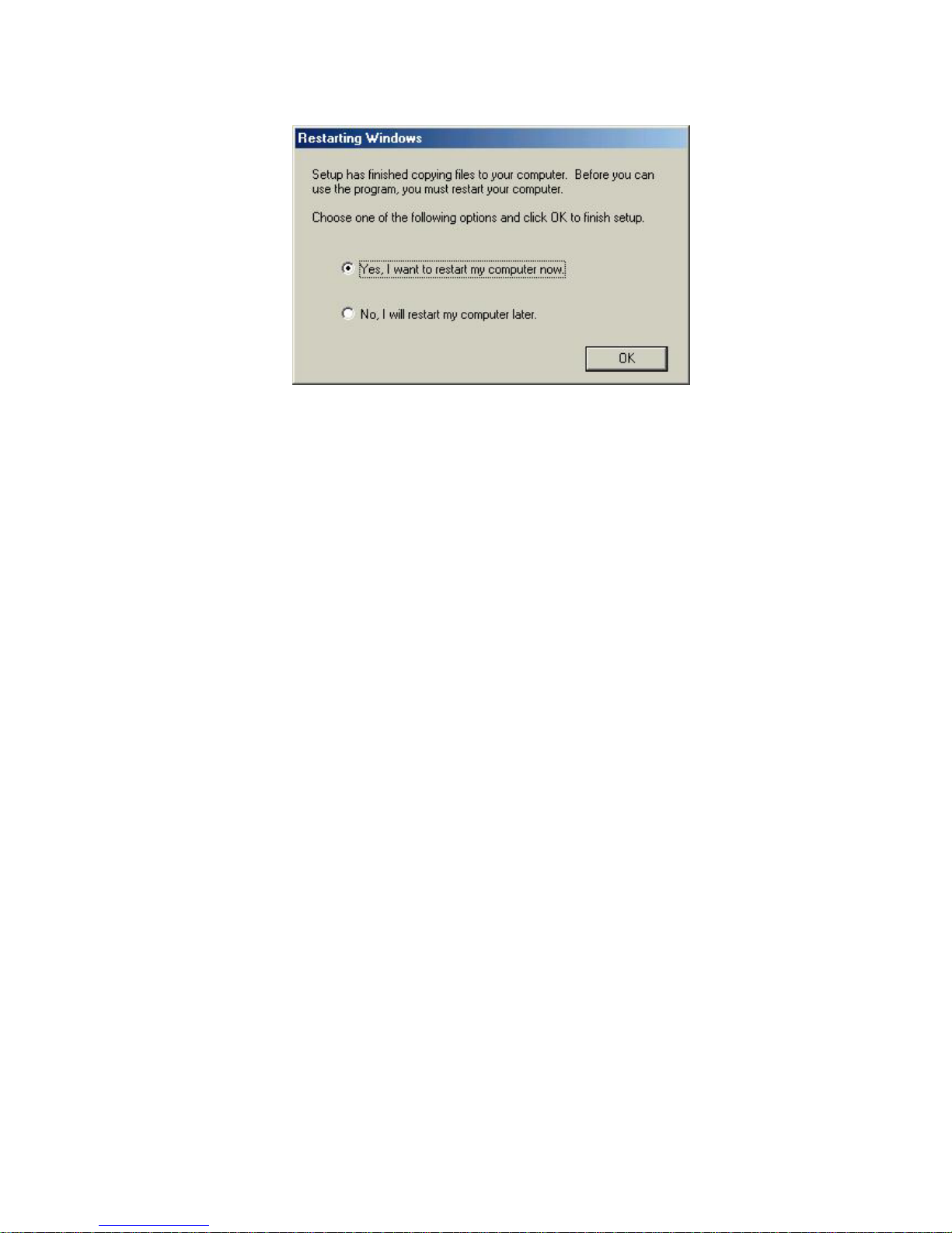
10. The “Restarting Windows” screen appears, choose “Yes, I want to restart my
computer now,” and “OK.”
Configuring the PenMount Windows 98/Me Driver
Upon restarting, the computer automatically finds the new 9000 controller board. The
touch screen is connected but not calibrated. Follow the procedures below to carry out
calibration.
1. After installation, click the PenMount Monitor icon “PM” in the menu bar.
2. When the PenMount Control Panel appears, click “Calibrate.”
PenMount Control Panel
The functions of the PenMount Control Panel are explained in the following sections.
Calibrate
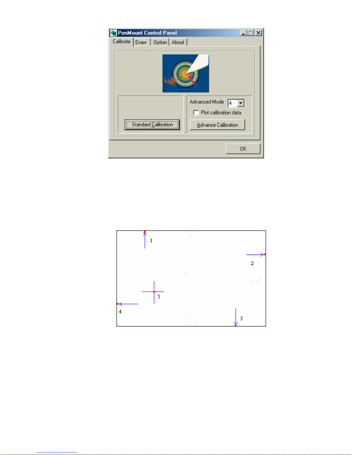
This function offers two ways to calibrate your touch screen. ‘Standard Calibration’
adjusts most touch screens. ‘Advanced Calibration’ adjusts aging touch screens.
Standard Calibration
Click this button and arrows appear pointing to red
squares. Use your finger or stylus to touch the red
squares in sequence. After the fifth red point
calibration is complete. To skip, press ‘ESC’.
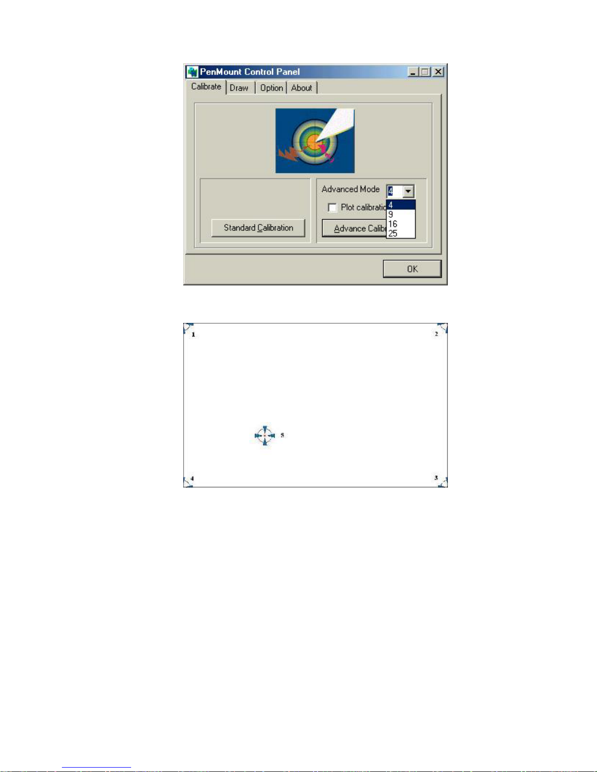
Advanced Calibration Advanced Calibration uses 4, 9, 16 or 25 points to
effectively calibrate touch panel linearity of aged
touch screens. Click this button and touch the red
squares in sequence with a stylus. To skip, press
ESC’.
Page 24
EX-91171 User Manual
24
NOTE: The older the touch screen is, the more Advanced Mode calibration points you need
for an accurate calibration. Use a stylus during Advanced Calibration for greater
accuracy.
Page 25
EX-91171 User Manual
25
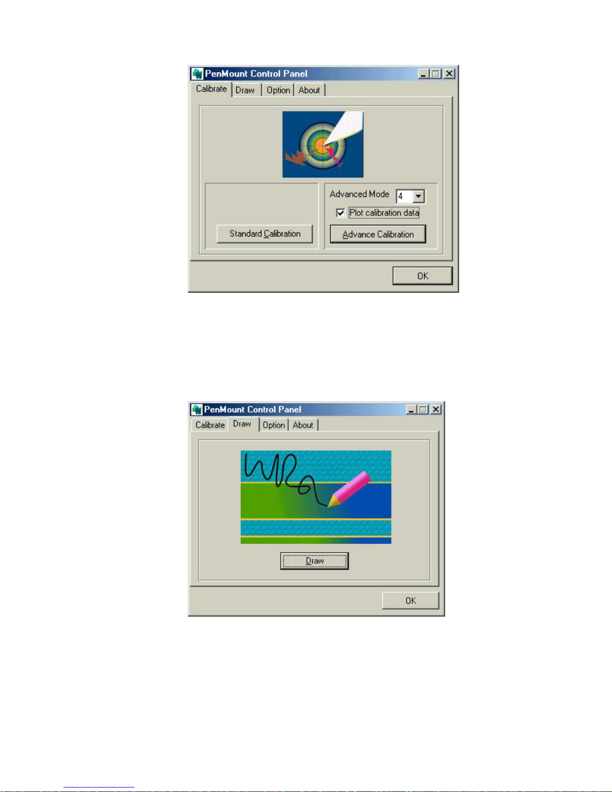
Plot Calibration Data Check this function and a touch panel linearity
comparison graph appears when you have finished
Advanced Calibration. The blue lines show linearity
before calibration and black lines show linearity
after calibration.
Page 26
EX-91171 User Manual
26
Draw
Tests or demonstrates the PenMount touch screen operation. The display shows touch
location. Click Draw to start.
Page 27

EX-91171 User Manual
27
Touch the screen with your finger or a stylus and the drawing screen will register touch
activity such as left, right, up, down, pen up, and pen down.
Click Clear Screen to clear the drawing.
Page 28
EX-91171 User Manual
28
Option
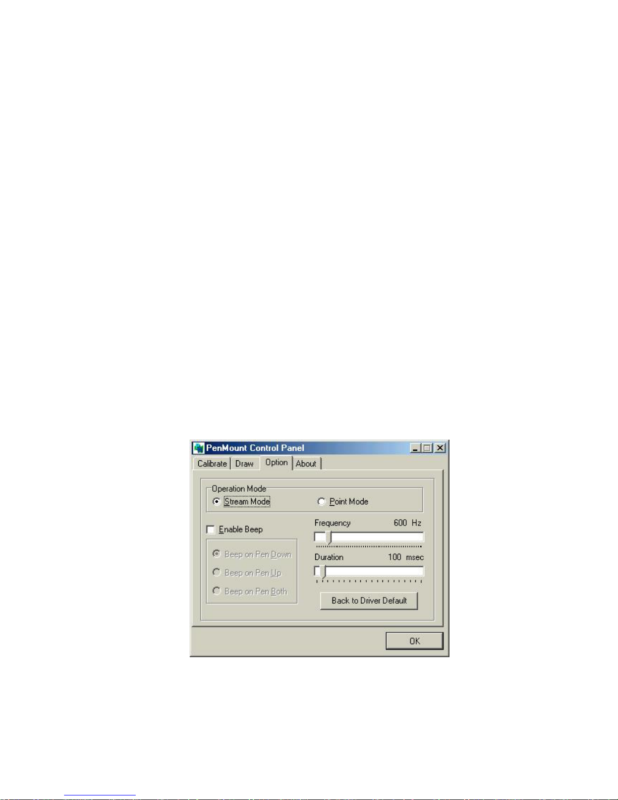
This panel function supports two modes—Operation Mode and Beep Sound
Mode—which allow configuration for specific touch screen applications, such as
point-of-sales (POS) terminals.
Operation Mode This mode enables and disables the mouse’s ability to
drag on-screen icons—useful for configuring POS
terminals.
Stream Mode – Select this mode and the mouse
functions as normal and allows dragging of icons.
Point Mode – Select this mode and the mouse only
provides a click function, and dragging is disabled.
Beep Sound Mode Enable Beep Sound – turns beep function on and off
Beep on Pen Down – beep occurs when pen comes
down
Beep on Pen Up – beep occurs when pen is lifted up
Beep on both of Pen Down/Up – beep occurs on both
Beep Frequency – modifies sound frequency
Beep Duration – modifies sound duration
`
Page 29
EX-91171 User Manual
29
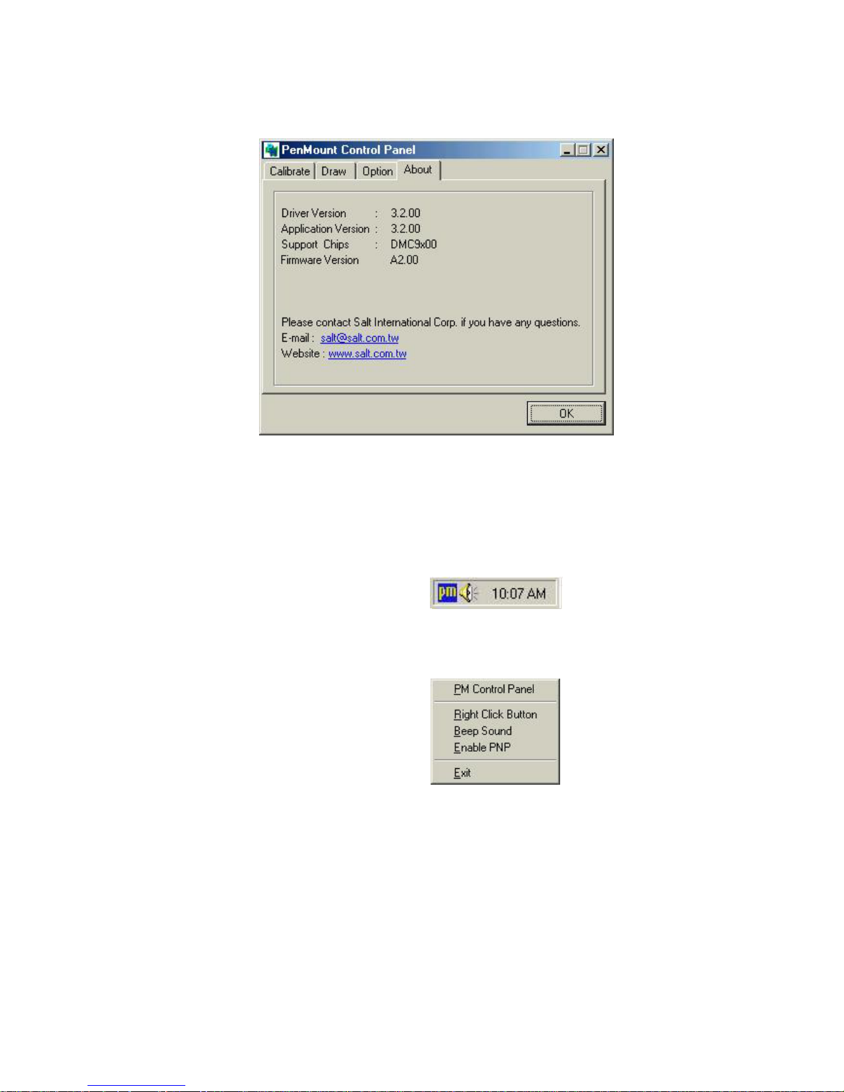
About
This panel displays information about the PenMount controller and this driver version.
PenMount Monitor Menu Icon
The PenMount monitor icon (PM) appears in the menu bar of Windows 98/ME system
when you turn on the PenMount Monitor in the PenMount Utilities.
The PenMount Monitor has the following functions:
Page 30

EX-91171 User Manual
30
Right Click Button When you select this function, a mouse icon appears
in the right-bottom of the screen. Click this icon to
switch between Right and Left Button functions.
Beep Sound Turns beep on or off.
Enable PNP Turns PNP on or off. When this is unchecked, PNP is
off. The RS-232 transfer signal is continuous when
the cable is unplugged and plugged into the serial
port.
Exit Exits the PenMount Monitor function.
PenMount Rotating Functions
The PenMount driver for Windows 98/ME supports several display rotating software
packages. The PenMount drivers for Windows 95, Windows 98/ME, Windows 2000/XP,
as well as Windows 98 USB and Windows ME/2000/XP support display rotating
software packages such as:
• Portrait’s Pivot Screen Rotation Software
• ATI Display Driver Rotate Function
• nVidia Display Driver Rotate Function
• SMI Display Driver Rotate Function
• Intel 845G/GE Display Driver Rotate Function
Page 31

EX-91171 User Manual
31
Configuring the Rotation Function
1. Install the rotation software package.
2. Choose the rotating function (0°, 90°, 180°, 270°) in the 3rd party software. The
calibration screen appears automatically. Touch this point and rotation is mapped.
NOTE: The Rotating function is disabled if you use Monitor Mapping
Page 32
EX-91171 User Manual
32
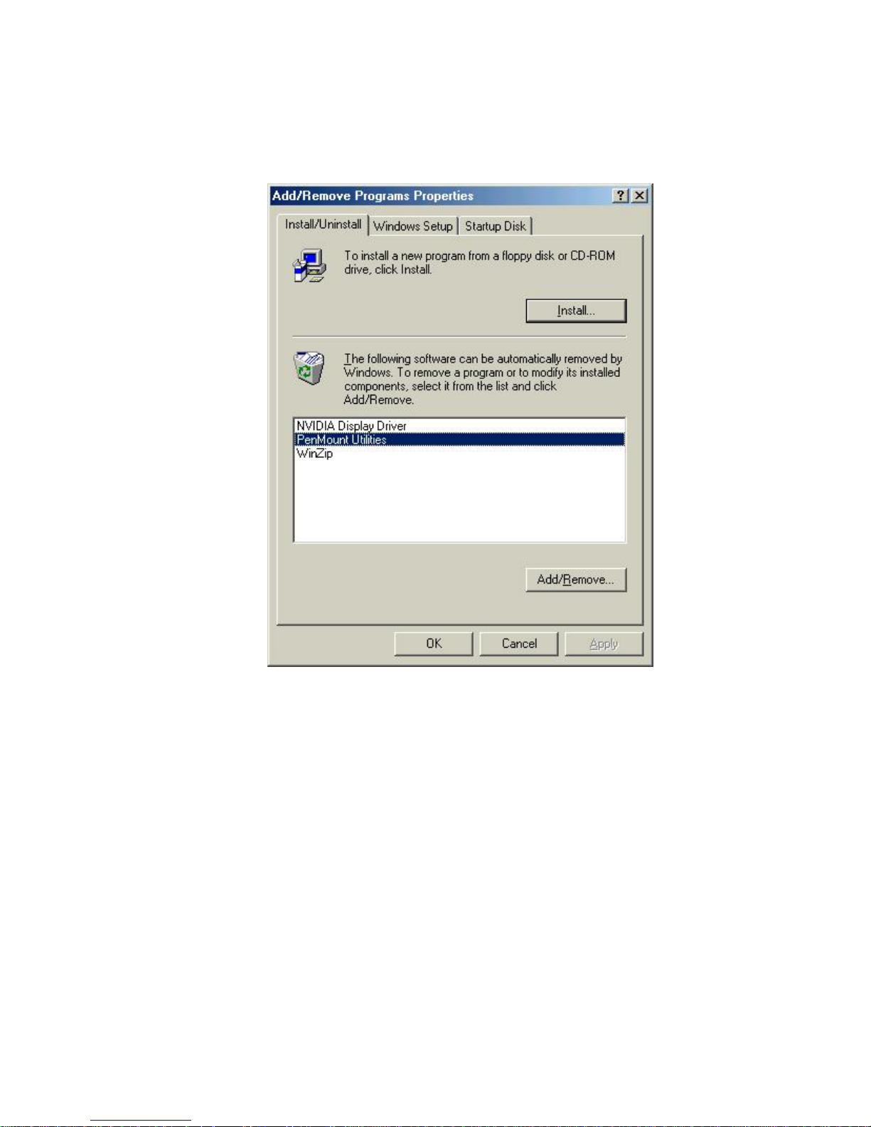
4.2 Uninstall the PenMount Windows 98/ME Driver
1. Exit the PenMount monitor (PM) in the menu bar.
2. From “PenMount Utilities” in “Programs”, select the “Uninstall” utility
3. This message appears: “Are you sure you want to completely remove ‘PenMount
Utilities’ and all its components?”
4. Select “Yes” to remove the PenMount Windows 98/ME driver.
5. Reboot system and the PenMount Windows 98/ME driver is removed from system.
Page 33
EX-91171 User Manual
33
4.3 Windows 2000/XP Driver Installation for 9036 Control Board
Before installing the Windows 2000/XP driver software, you must have the Windows
2000/XP system installed and running on your computer. You must also have the 9036
PenMount Serial Interface controller board installed. Contents of the PenMount
Windows 2000/XP driver folder are listed below:
DMC9000.inf
DMC9000.sys
DMC9000.cat
SETUP.EXE
If you have an older version of the PenMount Windows 2000/XP driver installed in your
system, please remove it first. Follow the steps below to install the PenMount Windows
2000/XP driver.
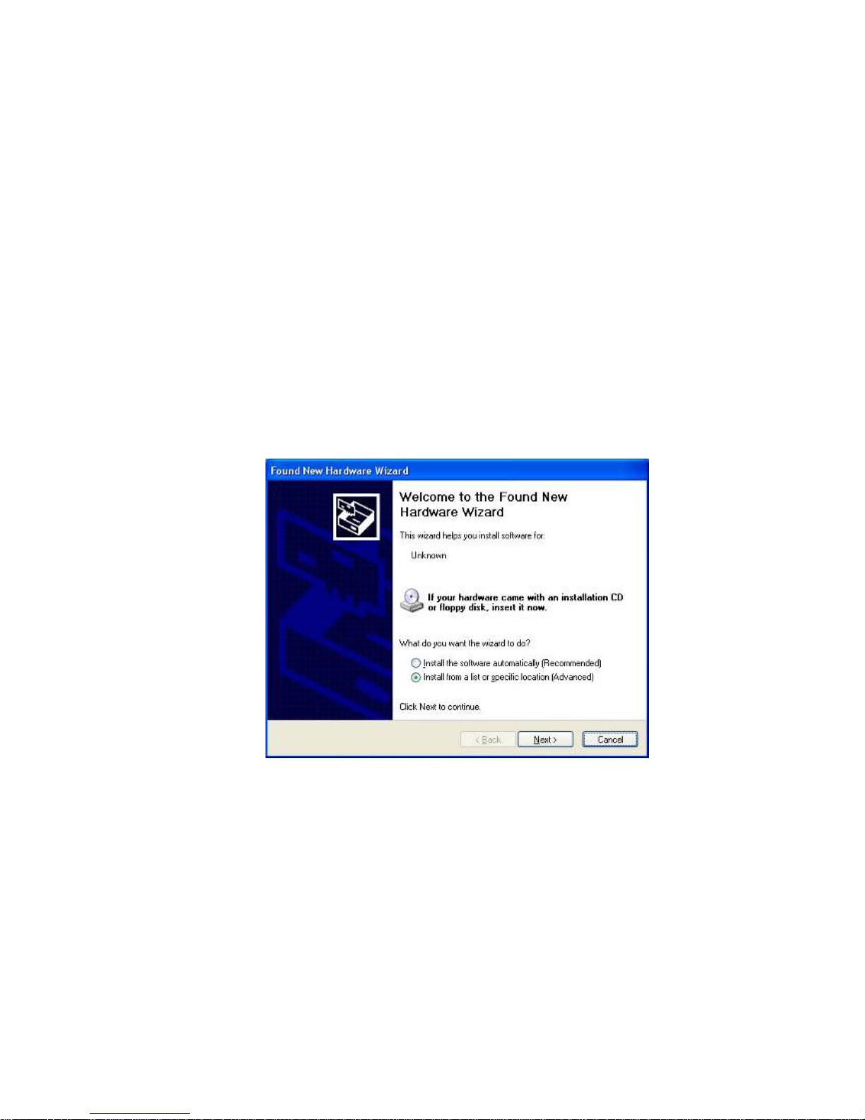
1. When the system first detects the controller board, a screen appears that shows
“Unknown Device”. Do not use this hardware wizard. Press Cancel.
Page 34
EX-91171 User Manual
34
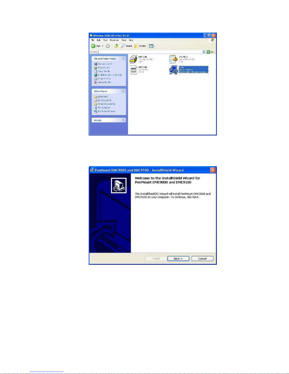
2. Insert the PenMount Driver CD-ROM. Go to the Windows 2000-XP Driver folder.
Click setup.exe.
3. The screen displays the installation wizard for the PenMount software. Click “Next”.
Page 35
EX-91171 User Manual
35
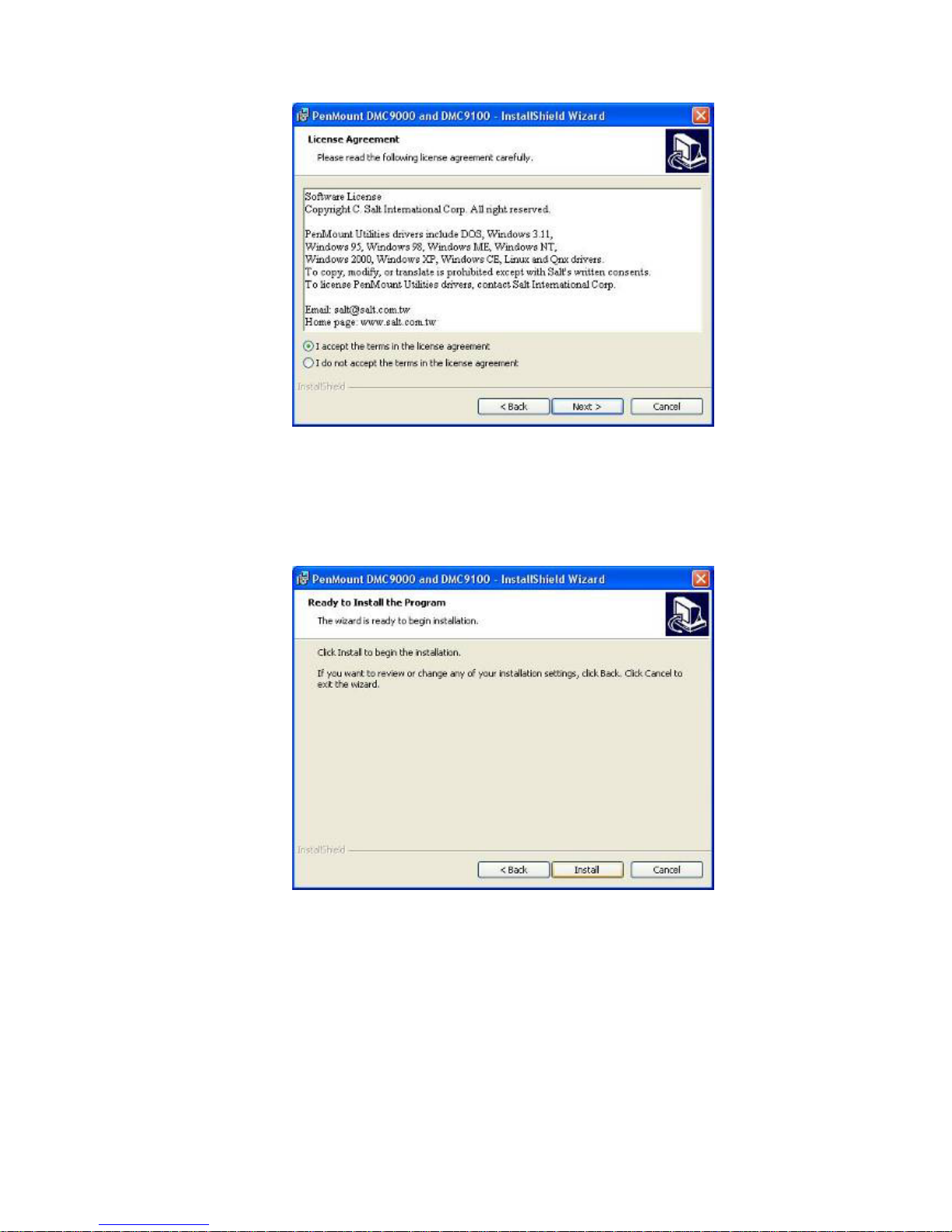
3. A License Agreement appears. Click “I accept…” and “Next”.
4. The “Ready to Install the Program” screen appears. Select “Install”.
Page 36
EX-91171 User Manual
36
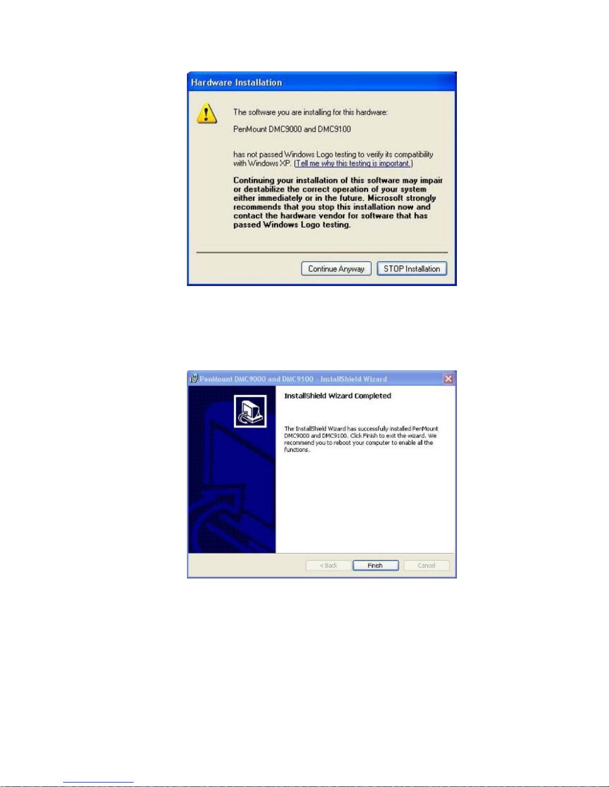
5. The next screen is “Hardware Installation”. Select “Continue Anyway”.
6. The “InstallShield Wizard Completed” appears. Click “Finish”.
Page 37
EX-91171 User Manual
37
4.4 Configuring the PenMount Windows 2000/XP Driver
Upon rebooting, the computer automatically finds the new 9036 controller board. The
touch screen is connected but not calibrated. Follow the procedures below to carry out
calibration.
1. After installation, click the PenMount Monitor icon “PM” in the menu bar.
2. When the PenMount Control Panel appears, click “Calibrate”.
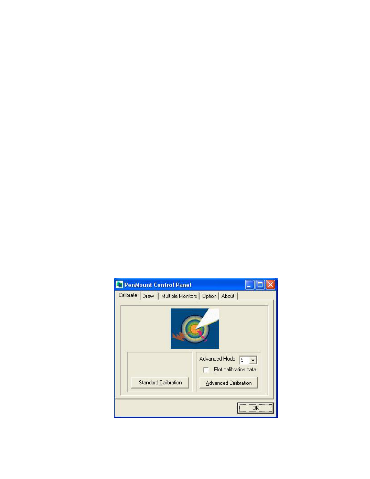
PenMount Control Panel
The functions of the PenMount Control Panel are Calibrate, Draw, Multiple Monitors,
Option, and About, which are explained in the following sections.
Calibrate
This function offers two ways to calibrate your touch screen. “Standard Calibration”
adjusts most touch screens. “Advanced Calibration” adjusts aging touch screens.
Standard Calibration
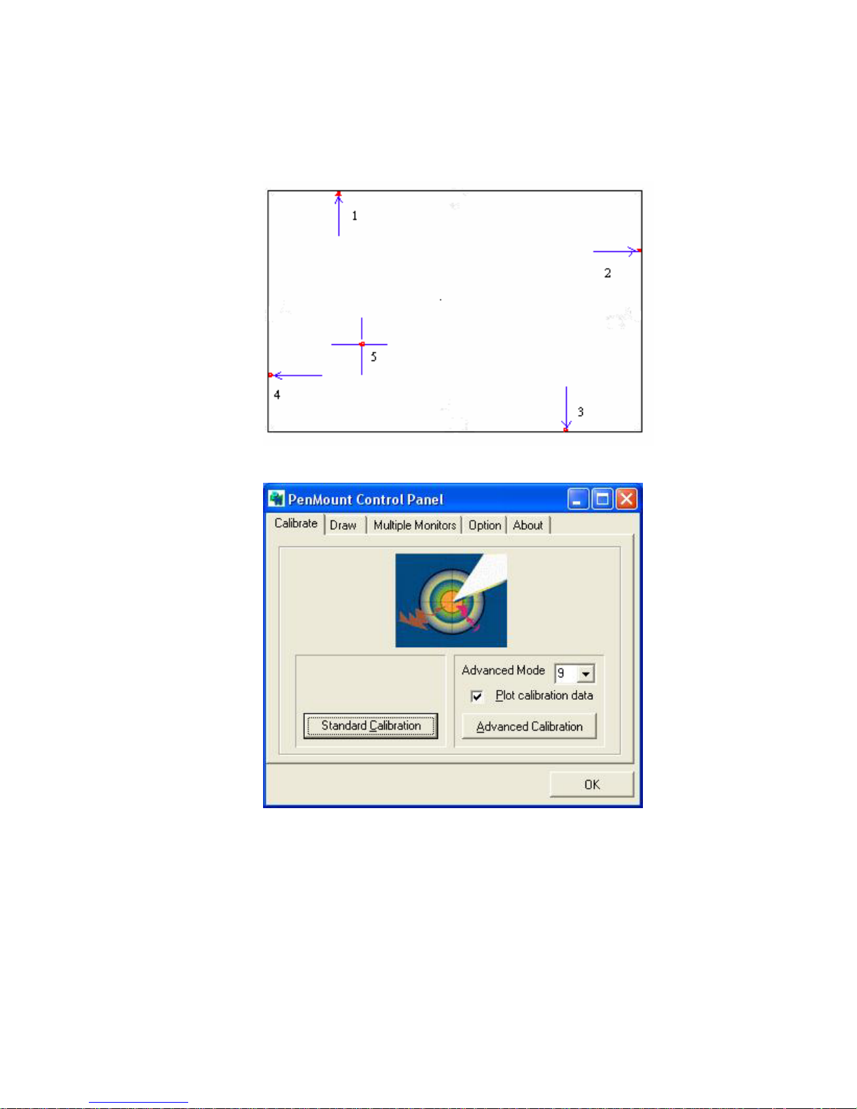
Click this button and arrows appear pointing to red
squares. Use your finger or stylus to touch the red
squares in sequence. After the fifth red point
calibration is complete. To skip, press ‘ESC’.
Advanced Calibration Advanced Calibration uses 4, 9, 16 or 25 points to
effectively calibrate touch panel linearity of aged
touch screens. Click this button and touch the red
squares in sequence with a stylus. To skip, press
‘ESC’.
Page 38
EX-91171 User Manual
38
NOTE: The older the touch screen is, the more Advanced Mode calibration points you need
for an accurate calibration. Use a stylus during Advanced Calibration for greater
accuracy.
Page 39
EX-91171 User Manual
39
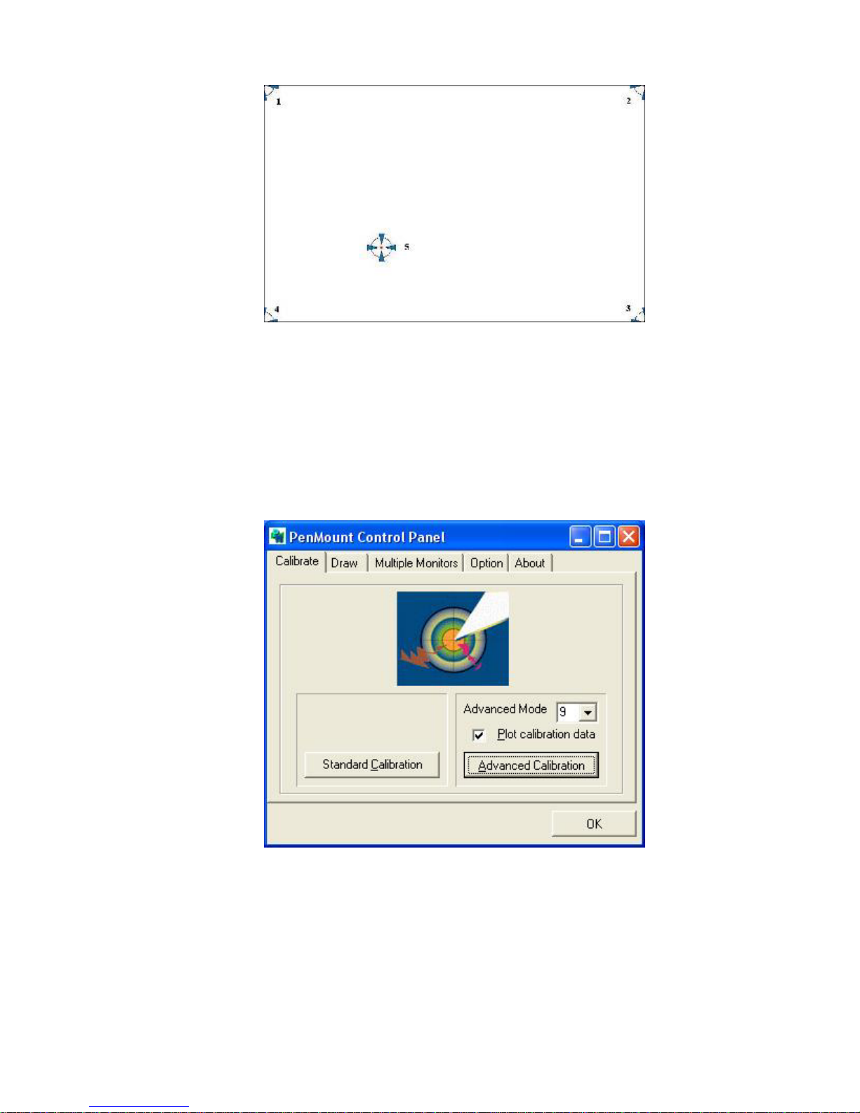
Plot Calibration Data Check this function and a touch panel linearity
comparison graph appears when you have finished
Advanced Calibration. The blue lines show linearity
before calibration and black lines show linearity
after calibration.
Page 40
EX-91171 User Manual
40
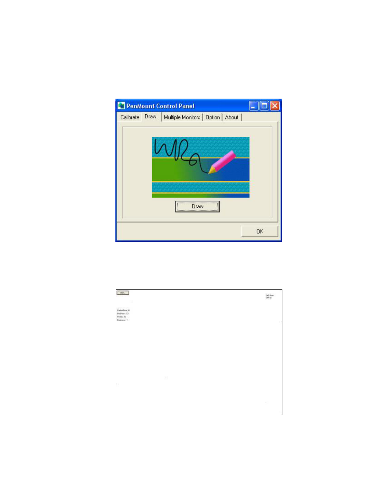
Draw
Tests or demonstrates the PenMount touch screen operation. The display shows touch
location. Click Draw to start. Touch the screen with your finger or a stylus and the
drawing screen will register touch activity such as left, right, up, down, pen up, and
pen down.
Touch the screen with your finger or a stylus and the drawing screen will register touch
activity such as left, right, up, down, pen up, and pen down.
Page 41

EX-91171 User Manual
41
Click Clear Screen to clear the drawing.
Multiple Monitors
Multiple Monitors support from two to six touch screen displays for one system.
The PenMount drivers for Windows 2000/XP support Multiple Monitors. This function
supports from two to six touch screen displays for one system. Each monitor requires its
own PenMount touch screen control board, either installed inside the display or in a
central unit. The PenMount control boards must be connected to the computer COM
ports via the RS-232 interface. Driver installation procedures are the same as for a
single monitor. Multiple Monitors support the following modes:
Windows Extends Monitor Function
Matrox DualHead Multi-Screen Function
nVidia nView Function
NOTE: The Multiple Monitor function is for use with multiple displays only. Do not use this
function if you have only one touch screen display. Please note once you turn on this
function the rotating function is disabled.
Page 42
EX-91171 User Manual
42
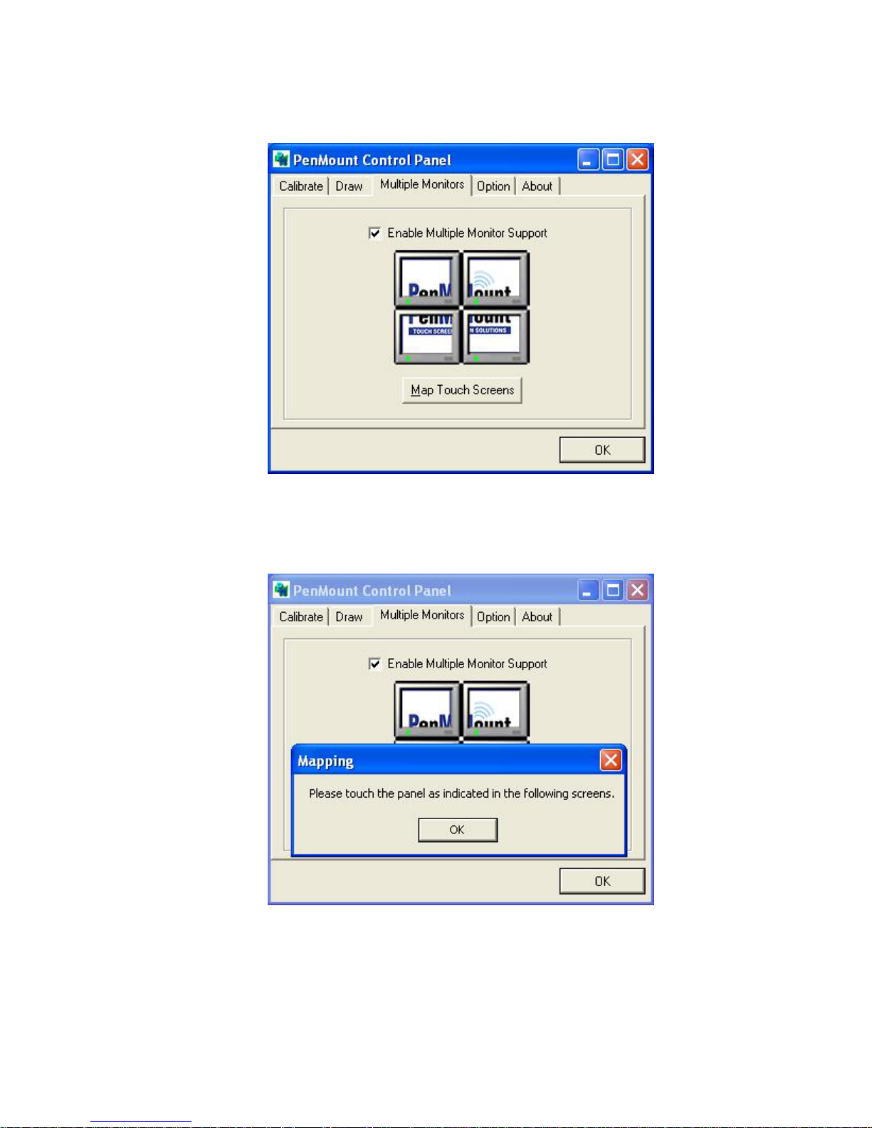
Enable the multiple display function as follows:
1. Check the Enable Multiple Monitor Support box; then click Map Touch Screens to
assign touch controllers to displays.
2. When the mapping screen message appears, click OK.
Page 43
EX-91171 User Manual
43
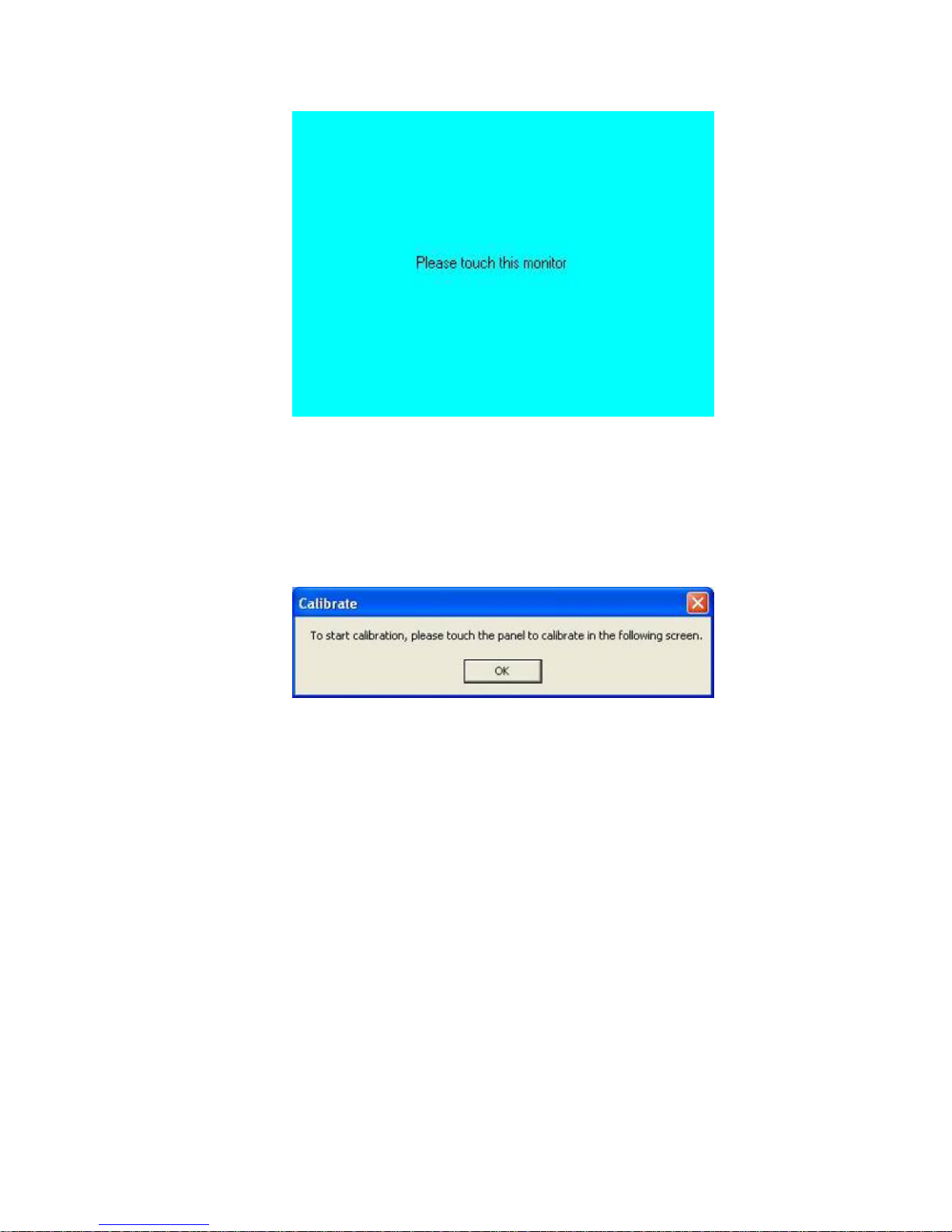
3. Touch each screen as it displays “Please touch this monitor”. Following this
sequence and touching each screen is called mapping the touch screens.
4. Touching all screens completes the mapping and the desktop reappears on the
monitors.
5. Select a display and execute the “Calibration” function. A message to start calibration
appears. Click OK.
6. “Touch this screen to start its calibration” appears on one of the screens. Touch the
screen.
7. “Touch the red square” messages appear. Touch the red squares in sequence.
8. Continue calibration for each monitor by clicking Standard Calibration and touching
the red squares.
NOTES: 1. If you use a single VGA output for multiple monitors, please do not use the
Multiple Monitor function. Just follow the regular procedure for calibration on each
of your desktop monitors.
2. The Rotating function is disabled if you use the Multiple Monitor function.
3. If you change the resolution of display or screen address, you have to redo Map
Touch Screens, so the system understands where the displays are.
Page 44
EX-91171 User Manual
44
About
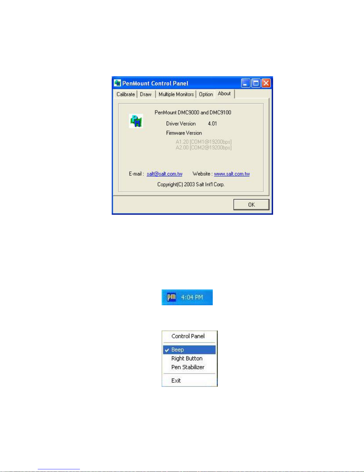
This panel displays information about the PenMount controller and this driver version.
PenMount Monitor Menu Icon
The PenMount monitor icon (PM) appears in the menu bar of Windows 2000/XP system
when you turn on the PenMount Monitor in the PenMount Utilities.
The PenMount Monitor has the following functions:
Page 45

EX-91171 User Manual
45
Beep Turns beep on or off.
Right Button When you select this function, a mouse icon appears
in the right-bottom of the screen. Click this icon to
switch between Right and Left Button functions.
Pen Stabilizer Check this function to reduce cursor vibration for
relatively unstable touch screens, or where there may
be excess vibration. Normally this function is not
checked.
Exit Exits the PenMount Monitor function.
Page 46

EX-91171 User Manual
46
PenMount Rotation Functions
The PenMount driver for Windows 2000/XP supports several display rotating software
packages. The PenMount drivers for Windows 95, Windows 98/ME, Windows 2000/XP,
as well as Windows 98 USB and Windows Me/2000/XP support display rotating software
packages such as:
• Portrait’s Pivot Screen Rotation Software
• ATI Display Driver Rotating Function
• nVidia Display Driver Rotating Function
• SMI Display Driver Rotating Function
• Intel 845G/GE Display Driver Rotating Function
Configuring the Rotation Function
1. Install the rotation software package.
2. Choose the rotating function (0°, 90°, 180°, 270°) in the 3rd party software. The
calibration screen appears automatically. Touch this point and rotation is mapped.
NOTE: The rotating function is disabled if you use Monitor Mapping
Page 47
EX-91171 User Manual
47
4.5 Uninstall the PenMount Windows 2000/XP Driver
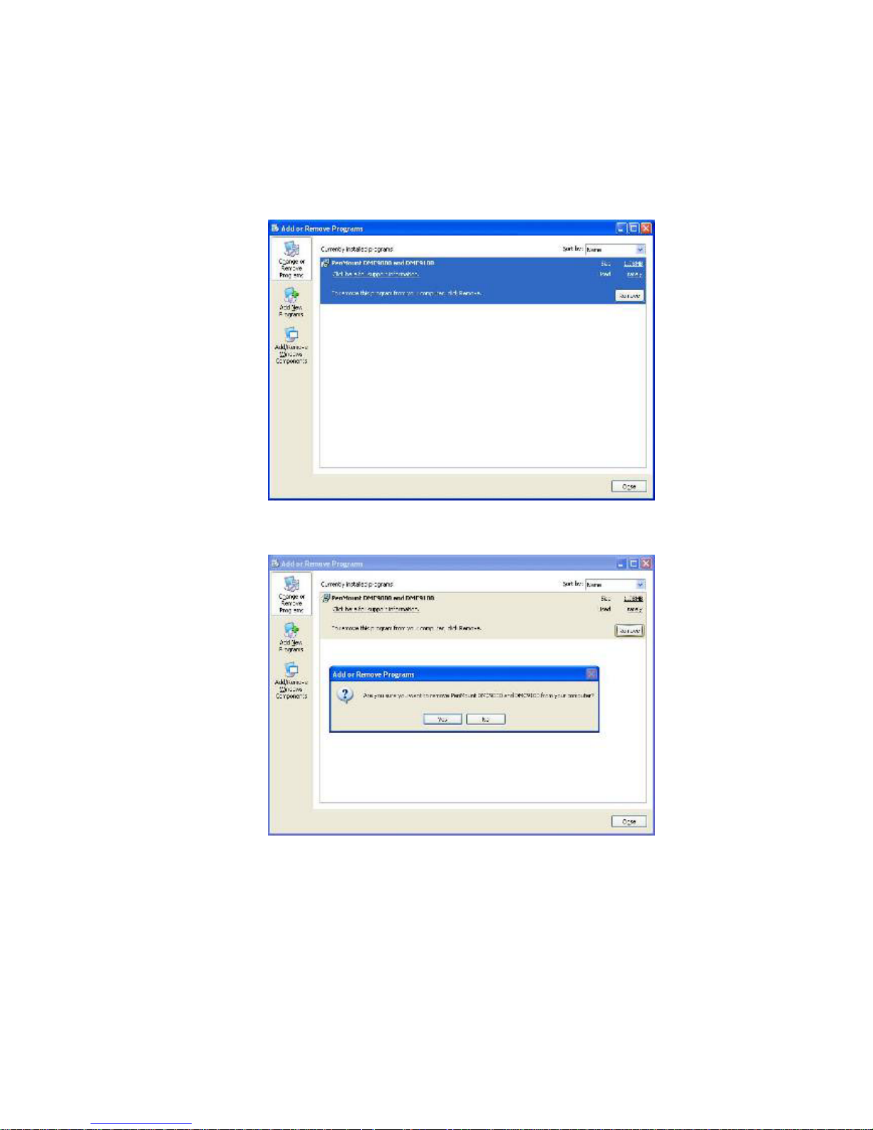
1. Exit the PenMount monitor (PM) in the menu bar.
2. Go to Settings, then Control Panel, and then click Add/Remove program. Select
PenMount DMC9000 and click the Add/Remove button.
3. Select PenMount DMC9000 and DMC9100. Click the Remove button.
4. Select “Yes” and “Close” to remove the PenMount Windows 2000/XP driver, and
reboot the system.
Page 48
EX-91171 User Manual
48
Chapter 5_____________________________
5.1 Software Functions
This chapter describes the special software functions that configure and adjust the
PenMount controller board and touch screen hardware. Please note that not all of the
functions are available for every driver. Software functions and their availability for
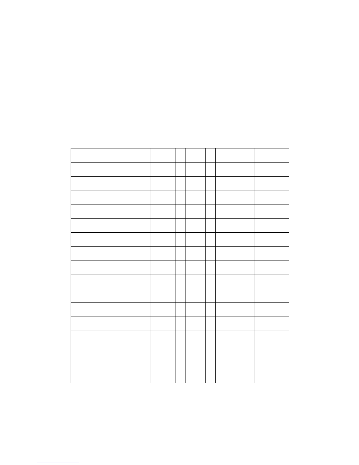
specific interface and systems are shown in the table below—a description for each
function follows:
Software Function DOS Win 3.1 95 98/Me NT 2000/XP CE Linux QNX
Standard Calibration
● ● ● ●■ ● ●■ ●■ ●■ ●
Advanced Calibration
●■ ● ●■ ●■
Multiple Monitors
●
Multi Device
■ ●■ ■
Rotation
● ●■ ● ●■
Stream/Point mode
●■ ●■
Drawing mode
● ● ● ●■ ● ●■ ●■
Beep Sound
● ● ● ●■ ● ●■ ●■ ●
Beep sound adjustable
●■ ●■
Wake up function
●■ ■
Showing linearity
●■ ●■
Right button
● ● ●■ ● ●■ ●■ ●
Hide cursor
● ● ● ●
Double click area and
speed adjustable
● ●
About
● ● ●■ ● ●■
● RS-232 Interface (9000 series)
■ USB Interface (5000 series)
Page 49

EX-91171 User Manual
49
5.2 Software Function Description
Description for each of the software functions shown in the table above follows:
Standard Calibration
The Standard Calibration function lets you match the touch screen to your display so that
the point you touch is accurately tracked on screen. Standard calibration only requires
four points for calibration and one point for confirmation. Under normal circumstances,
Standard Calibration is all you need to perform an accurate calibration.
Advanced Calibration
The Advanced Calibration function improves the accuracy of calibration by using more
involved engineering calculations. Use this function only if you have tried the Standard
Calibration and there is still a discrepancy in the way the touch screen maps to the
display. You can choose 4, 9, 16 or 25 points to calibrate, though we suggest that you
first try 9 points, if it is still not tracking well then try 16 or 25 points. The more points you
use for calibration, the greater the accuracy. Errors in calibration may occur due to
viewing angle, or individual skill, and there may be little difference in using 16 or 25
points. Note that a stylus is recommended for the most accurate results.
Multiple Monitors
Until now most touch screen systems only support one monitor, and users of multiple
monitors have not been able to use touch screen systems. This situation has inspired
PenMount to design and develop Multiple Monitors support using the PenMount 9036
control board and Windows 2000/XP driver. Our advanced design supports from 2 to 6
monitors that can be split horizontally or vertically.
Requirements
Before using the Multiple Monitor function, you need the following:
1. A display card that supports multiple monitors such as the Matrox, nVidia, ATI, etc.
(Two or more display cards supported by Windows are also OK.)
2. Two or more touch screens
3. Two or more serial ports
4. Two or more PenMount 9000 control boards such as the 9036, 9026, 9084, or
90A4
5. The PenMount 9000 Windows 2000/XP v4.01 or greater software driver
Before using Multiple Monitors you must have two or more monitors that are in extension
mode. For display cards that support multiple monitors, we suggest you consider Matrox,
Page 50
EX-91171 User Manual
50
nVidia, or ATI cards and inquire about operation and usability issues.
Note: Before you can use multiple monitors, you need to map each monitor.
Multiple Devices
The Multiple Devices function is designed to let you use two or more monitors to display
the same image. Software that supports this function includes the PenMount 9000
2000/XP drivers and the PenMount 5000 98/Me/2000/XP/CE drivers. The drivers for
PenMount 9000 can support up to six control boards, and the drivers for PenMount 5000
support up to 16
Comparing Functions
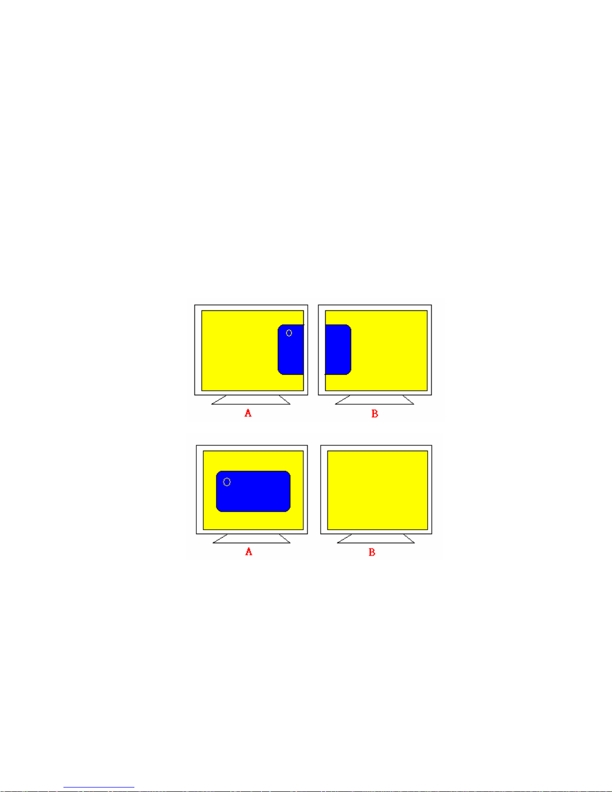
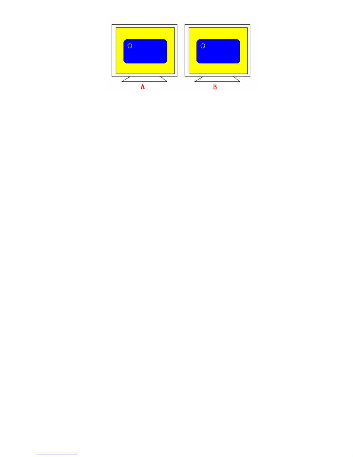
The difference between the Multiple Monitors function and the Multiple Devices function
are illustrated below:
or
The Multiple Monitors function shown above extends the screen into 2 or more monitors.
Page 51
EX-91171 User Manual
51
The Multiple Devices function displays the same image on two or more monitors.
Requirements
Before using the Multiple Monitors function, you need the following:
1. A display card that supports Dual Monitors such as the Matrox, nVidia, ATI, etc.,
or that outputs into a 1-into-2 VGA signal box
2. Two or more touch screens
3. Two or more serial ports or USB ports
4. Two or more PenMount 9000 control boards such as the 9036, 9026, 9084, or
90A4, or PenMount 5000 control boards such as the 5184 or 51A5
5. If using the PenMount 9000 control board the driver must be the PenMount 9000
Windows 2000/XP v4.01 or greater software driver
6. If using the PenMount 5000 control board the driver must be for Windows
98/ME/2000/XP/CE
9000 Control Boards
To use multiple devices with 9000 Control Boards:
1. Configure your computer hardware.
2. Attach each 9000 Control Board to a different computer’s serial port.
3. Install the appropriate PenMount software driver in each computer.
4. Use each driver’s Calibration function to calibrate each computer’s touch screen.
You must calibrate each touch screen before configuration is complete.
Rotation
There are currently a number of software packages on the market that support rotating
monitors 0°, 90°, 180°, and 270°. However, you will not be able to use a touch screen
unless it is matched to the appropriate rotation. Our rotation configuration function allows
you to easily match the touch screen when you rotate your monitor.
If you use a rotating monitor, you will need a display card such as from nVidia, Intel, SMI
or ATI and software such as Portrait Pivot Pro. For software operation and features,
please refer to your software manual.
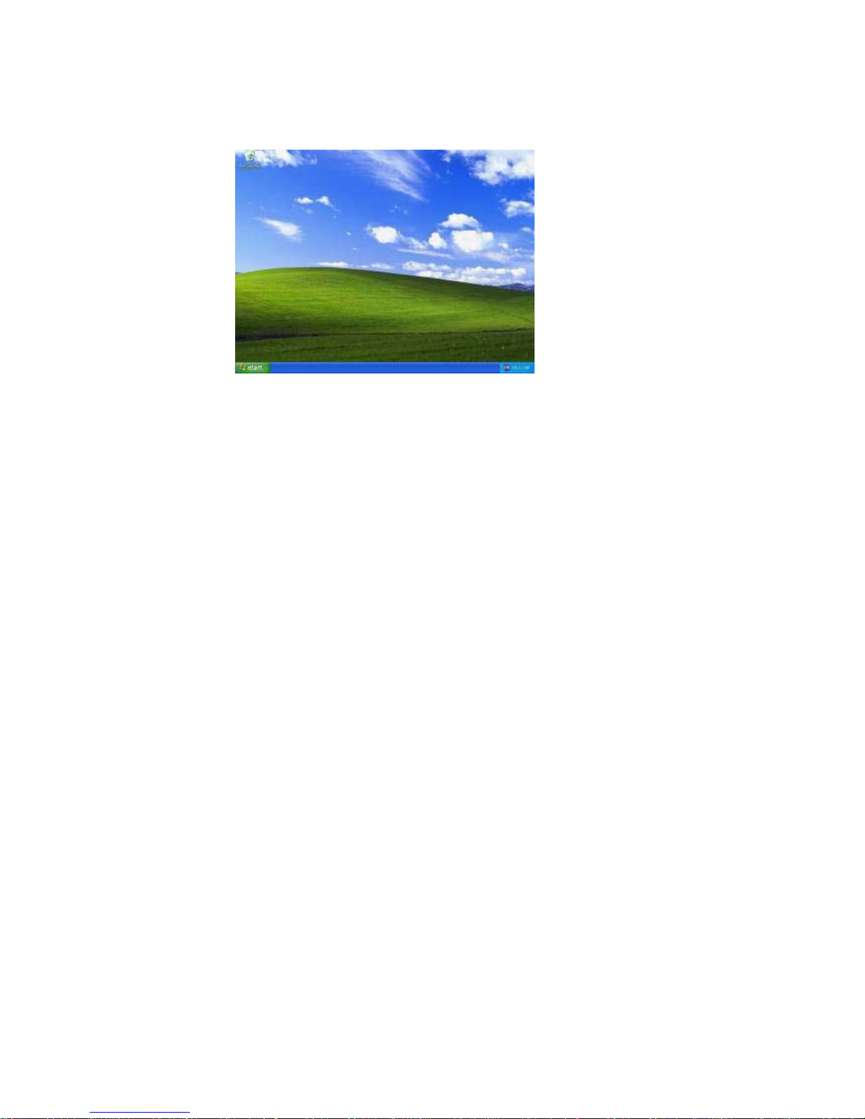
Configuring the rotation function is easy. Select this option and a ‘point’ appears for you
Page 52
EX-91171 User Manual
52
to touch. Once the point is touched, the software driver understands which degree you
plan to rotate your display. The rotation function supports 90, 180 and 270 degrees
rotation.
0 degrees
Page 53

EX-91171 User Manual
53
90 degrees
180 degrees
270 degrees
Page 54

EX-91171 User Manual
54
Stream/Point Mode
Stream and point modes control the touch and drag function of the touch screen. The
point mode only allows “touch” interaction with the screen and does not allow the user to
drag objects. The point mode is useful for maintaining the location of screen icons such
on POS terminals. The stream mode allows a user to touch and drag icons and other
items around on the screen, similar to using a mouse.
Drawing Mode
Drawing mode is a utility that lets the user draw on the screen using a finger or stylus.
This allows the user to test the touch screen and touch controller to see if it is operational
or is mapped correctly. The drawing mode can display either the matrix address of points
touched or just show lines drawn. One of the PenMount driver’s strengths is a special
mathematical algorithm that minimizes the occurrence of noise and smooths the drawing
of lines.
Beep Sound
All of PenMount’s drivers support the beep sound function; however, some PC systems
may only offer a fixed buzzer sound.
Beep Sound Adjustable
Software drivers for Windows systems let the user adjust the frequency and length of the
beep sound. The drivers let the user adjust the desired touch screen sound, as well as
turn the sound off.
Wake Up Function
The Wake Up function lets the user touch the screen and wake the system up from
‘suspend’ mode.
Point Calibration Data
The Plot Calibration Data function displays the touch screen linearity map, which is
available if the PenMount driver provides an Advance Calibration function when touch
screens age their touch linearity declines. This non-linearity is apparent when the
touched point on the touch screen is not the same as the point on the display. The plot
calibration data function shows the linearity status of the touch screen. This is only a
support function for the user. The exact linearity of a touch screen requires a linearity
test machine.
Page 55

EX-91171 User Manual
55
Right Button
The Right Button function simulates the right button function of a mouse. Click the right
button and the user can only touch the screen once and the driver changes the touch
definition to the left button.
Hide Cursor
The Hide Cursor function keeps the cursor arrow and other cursor symbols from
appearing when using the touch screen. The cursor appears when the user turns this
function off.
Cursor Offset
The Cursor Offset function lets the user adjust the position of the touch point to a desired
location away from the real touch point.
Double-Click Area and Speed
The Double-Click Area and Speed function lets the user adjust the double-click area and
speed to their personal preference.
About
This option shows the exact version of the drivers and controller firmware. Updated
drivers are available for download on the PenMount website.
Page 56
EX-91171 User Manual
56
Appendix A: Board Descriptions & Specifications
This appendix provides information on controller board features and specifications.
PenMount 9036 Control Board
The PenMount 9036 control board is configured for the RS-232 interface and it supports
4-wire, 5-wire and 8-wire touch screens.
PenMount 9036 Features
• DMC9000 touch controller
• Diagnostic LED on board
• Supports PnP and non-PnP mode
• Supports 4-wire, 5-wire and 8-wire touch screen
• Baud rate 19200 or 9600 bps selectable
• Automatic pin assignment adjustment
• Input voltage is 5V to 12V
• Bundled with PenMount drivers, which are also available for download from our
website
Connector Pin Definitions
Pin definitions for the two connectors on the PenMount 9036 control board follow:
Connector Pin Definitions for Touch Screen
Pin definition
/ wires
4-wire
touch screen
5-wire
touch screen
8-wire
touch screen
PIN 9 N/A N/A Right Sense
PIN 8 N/A N/A Left Sense
PIN 7 N/A N/A Bottom Sense
PIN 6 N/A Sense Top Sense
PIN 5 Right LR Right
PIN 4 Left LL Left
PIN 3 Bottom UR Bottom
PIN 2 Top UL Top
PIN 1 Ground Ground Ground
Page 57

EX-91171 User Manual
57
Connector Pin Definitions for Power and RS-232
Power Lines RS-232 Interface
Pin # PIN 1 PIN 2 PIN 3 PIN 4 PIN 5 PIN 6
Definition Ground 5V~12V power RTS TXD RXD Ground
Page 58
EX-91171 User Manual
58
Appendix B: Controller IC Specifications
This appendix offers information on touch screen controller IC features and specs.
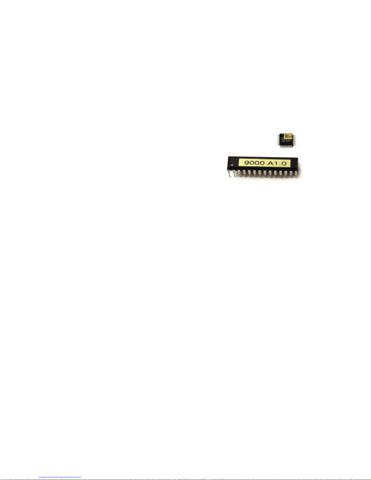
PenMount DMC9000 Touch Screen Controller IC
The PenMount DMC9000 is the best-performance touch screen controller. Designed
with PnP features for new system trends, it offers RS-232 touch screen interface. The
DMC9000 is designed for those who need an all-in-one solution with a built-in A/D
converter for a denser total printed circuit board.
Electrical Specifications
Touch Screen: 4, 5 & 8 wire
Package: 28-pin PDIP or 32-pin TQFP
Communications: RS-232
Characteristics:
8-bit RISC microprocessor with built-in
functions including 10-
b
it ADC, UART, Timer,
Counter, Comparator, Watchdog, Memory, etc.
Voltage Range: + 4.0V to +6.0V
Power Consumption:
(at 4 MHz, 3V)
Active: 3.4 mA / Idle Mode: 1.4mA
Power Down Mode: <1 µA
Operating Temperature: -40
o
C to +85o C
Storage Temperature: -65
o
C to +150o C
Volt. on RESET with respect
to Ground:
-1.0V to +13.0V
DC Current per I/O Pin: 40.0 mA
DC Current Vcc and GND Pins: 300.0 Ma
Driver Software
DOS, Windows 3.11, Windows 95/98/ME, Windows NT/2000/XP, Linux, QNX, Windows
CE (for both X86 and SA CPUs)
Page 59
EX-91171 User Manual
59
Appendix_____________________________
Panel/VESA Mounting
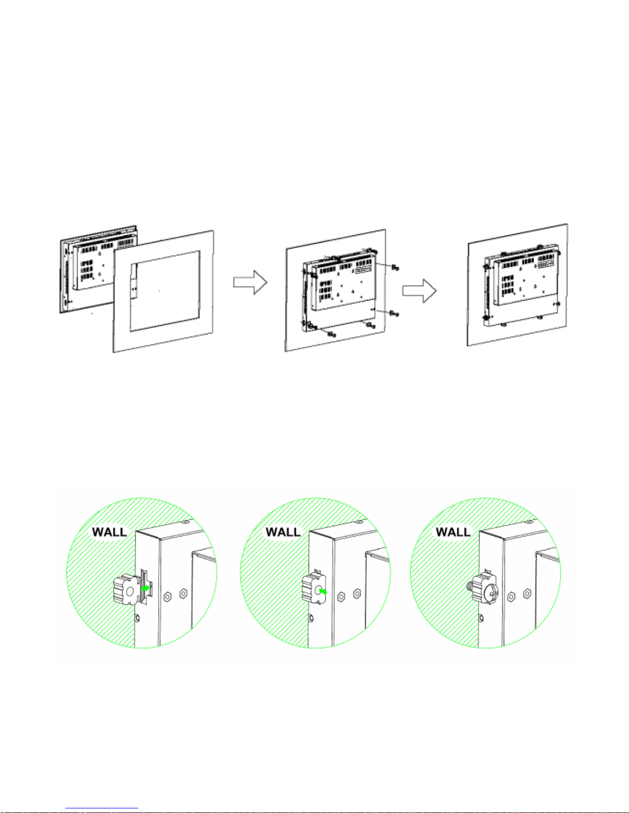
The EX-91171 display monitor is designed to be panel- or VESA 100-mounted as shown in Figure A
and Figure B. Just carefully place the unit through the hole and tighten the given 8 screws from the
rear to secure the mounting.
Figure A: Panelmounting of the EX-91171
How to Mount
1. Just insert the bracket into the hole 2. Slightly push the bracket back 3. And screw it tight.
as the arrow shows.
Page 60
EX-91171 User Manual
60
VESA 75 Mounting (optional)
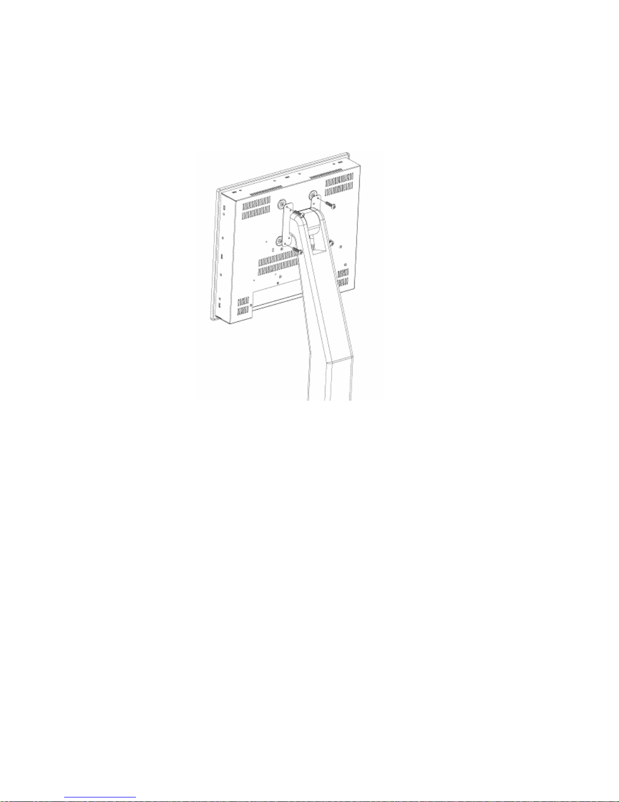
The EX-91171 display monitor can be VESA-mounted as an option. Just carefully mount the arm onto
the rear of the unit by fastening the given four screws as shown in Figure B.
Figure B: VESA 100 mounting of the EX-91171
 Loading...