

Page 1

OPERATION MANUAL
TOPS DIGITAL VIDEO RECORDER
TOPS DVR
TOPS DVR
Operation Manual
1
Page 2

OPERATION MANUAL
WARNING & CAUTION
All cautions and warnings on this manual should be noted failure to heed this warning &
caution will result in serious damage
WARNING
CAUTION
This symbol indicates that dangerous voltage constituting
a risk of electric shock is present within this unit
This symbol indicates that it may cause injury, damage and
other harmful results
2
Page 3
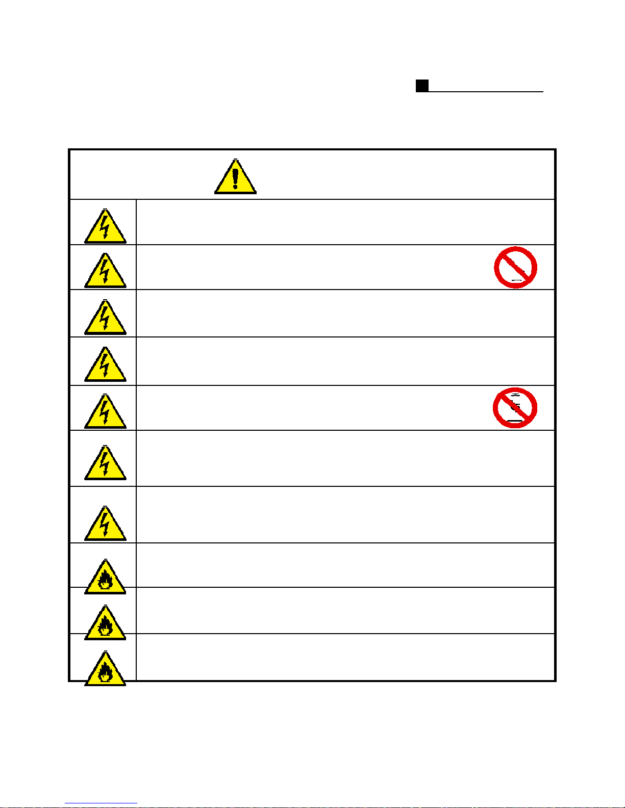
WARNINGS
Verify that the voltage is set correctly for user location
Do not touch the cord with wet hand
it may cause severe electric shock
Be sure that power is plugged in securely
(may cause fire if the connection is unstable)
Do not pull on the power cord
(may cause fire or electric shock if cord is damaged)
OPERATION MANUAL
Do not disassemble or reconstruct product
(may cause fire, electric shock or defects)
When in notice of smoke or weird smell, please stop usage and pull out the
power plug and contact the service center
(continued usage may cause fire or electric shock)
Do not place or drop metallic objects (coins, hair pin, metal) or easily
flammable products (matches, paper) in the ventilation of the product
(may cause fire or electric shock)
Do not place any liquid filled objects on the product
(may cause fire, electric shock or other injuries)
Avoid direct sunlight, heating equipment and electric equipment
(danger of fire)
Do not install product in areas of high humidity, dust or is soot-covered
(may cause fire, electric shock or defects)
3
Page 4
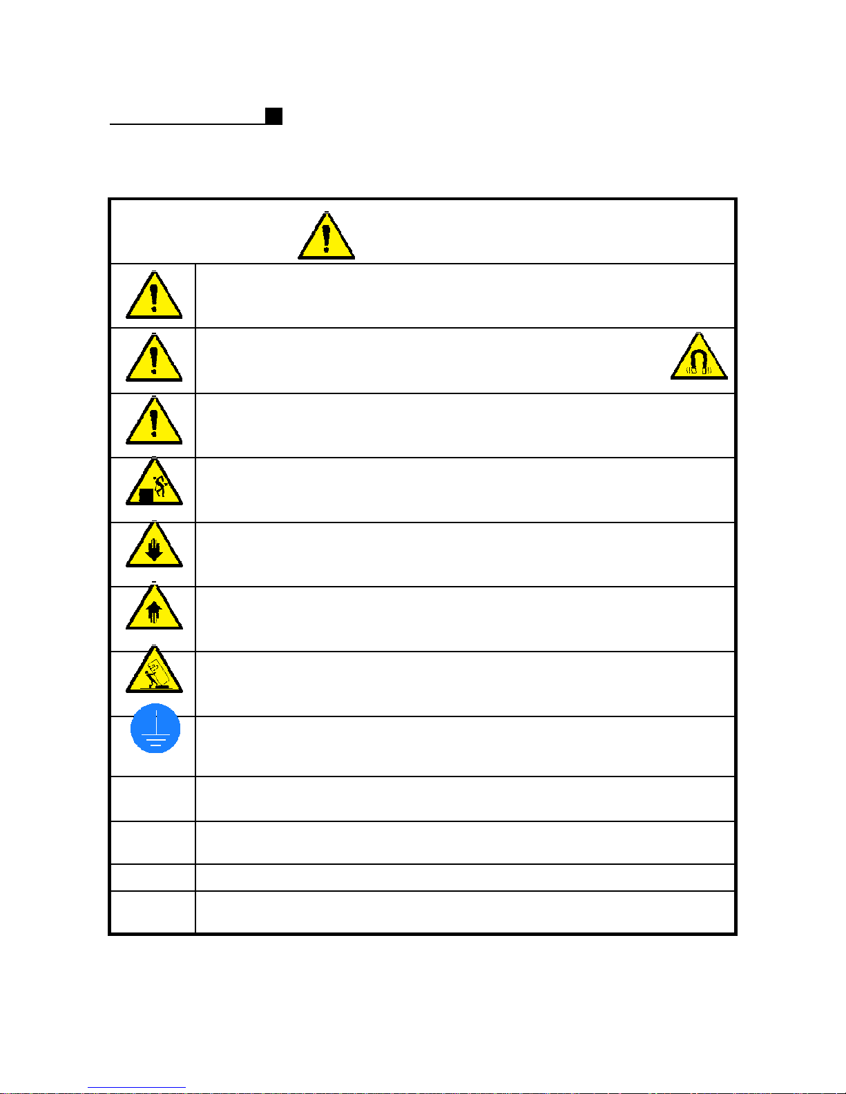
OPERATION MANUAL
Do not place heavy objects on product
(may cause injury)
Avoid areas of magnetic fields and severe vibration
(may cause defect in product)
Do not drop the product or cause sudden impacts
This product is heavy be careful when moving this product
CAUTIONS
Avoid installation in cold areas
This product is designed to operate under max 40℃
Avoid installation in uneven areas
(may cause defect in product)
To product use hour it uses the all the member cable where becomes the
ground connection it wishes
When cleaning the product, do not use water, but use a dry cloth to gently
wipe the product
Before operation, become familiar with all the special features and warning
associated with this equipment and read this manual carefully
Back up the important data
Single phase power supply operation is not recommended to prevent a power
supply failure ups is strongly recommended
4
Page 5

OPERATION MANUAL
INSTALLATION
INSTRUCTION
1) This device designed to operate under max 40℃ when you install this device in
the rack, please consider the max ambient temperature please install this device
proper ambient temperature of all part
2) Caution : when you install this device in the rack, the operating ambient
temperature may be greater than room ambient please consider this condition and
simulate the max temperature and install in an environment compatible temperature
3) Reduced air flow : installation of this device in a rack should be such that the
amount of air flow required for safe operation of this device is not compromised
please provide enough space to get the proper air flow
4) Mechanical loading – mounting of this device in the rack should be such that a
hazardous condition is not achieved due to uneven mechanical loading
5) Circuit overloading : please read the rating in the nameplate and consider
appropriate power supply and supply wiring
6) When you are using like a power strips except direct connections to the branch
circuit, please make sure to connect reliable earthing maintained
NOTE: This equipment has been tested and found to comply with the limits for a Class A digital
device, pursuant to part 15 of the FCC rules These limits are designed to provide reasonable
protection against harmful interference when the equipment is operated in a commercial environment
This equipment generates, uses, and can radiate radio frequency energy and, if not installed and
used in accordance with the instruction manual, may cause harmful interference to radio
communications Operation of this equipment in a residential area is likely to cause harmful
interference in which case the user will be required to correct the interference at his own expense
Connecting Power source to System Using 110V power source Make sure power select switch set to
115V(110V use)
Using 220V power source Make sure power select switch set to 230V(220V use)
NOTICE: For U S A and Canada regions; use only UL listed CSA labeled detachable power cord, 3conductor, 18 AWG, SVT or SJT type, plug rounding type parallel blade, cord connector body-IEC
320 style to mate with appliance inlet on product
IMPORTANT The only way to disconnect power completely is to unplug the power cord
Make sure at least one end of the power cord is within easy reach so that you can unplug the
computer when you need to
CAUTION: DANGER OF EXPLOSION IF BATTERY IS INCORRECTLY REPLACED REPLACE ONLY WITH THE SAME OR
EQUIVALENT TYPE RECOMMENDED BY THE MANUFACTURER DISCARD USED BATTERIES ACCORDING TO THE
MANUFACTURER’S INSTRUCTIONS
WARNING
This is a class A product In a domestic environment this product may cause radio interference in
which case the user may be required to take adequate measures
Changes or modifications not expressly approved by the manufacturer could void the user’s authority
to operate the equipment
5
Page 6

TABLE OF
CONTENTS
OPERATION MANUAL
81. INSTALLATION ㅡㅡㅡㅡㅡㅡㅡㅡㅡㅡㅡㅡㅡㅡㅡㅡㅡㅡㅡㅡㅡㅡㅡㅡㅡㅡㅡㅡㅡㅡ
91.1 Product Contents ㅡㅡㅡㅡㅡㅡㅡㅡㅡㅡㅡㅡㅡㅡㅡㅡㅡㅡㅡㅡㅡㅡㅡㅡㅡ
101.2 Front Layout ㅡㅡㅡㅡㅡㅡㅡㅡㅡㅡㅡㅡㅡㅡㅡㅡㅡㅡㅡㅡㅡㅡㅡㅡㅡ
111.3 Rear Layout ㅡㅡㅡㅡㅡㅡㅡㅡㅡㅡㅡㅡㅡㅡㅡㅡㅡㅡㅡㅡㅡㅡㅡㅡㅡㅡㅡ
142. SURVEILLANCE ㅡㅡㅡㅡㅡㅡㅡㅡㅡㅡㅡㅡㅡㅡㅡㅡㅡㅡㅡㅡㅡㅡㅡㅡㅡㅡㅡㅡㅡ
152.1 Surveillance ㅡㅡㅡㅡㅡㅡㅡㅡㅡㅡㅡㅡㅡㅡㅡㅡㅡㅡㅡㅡㅡㅡㅡㅡㅡㅡㅡㅡ
182.2 Preset Setting ㅡㅡㅡㅡㅡㅡㅡㅡㅡㅡㅡㅡㅡㅡㅡㅡㅡㅡㅡㅡㅡㅡㅡㅡㅡㅡㅡ
182.3 1CH Search ㅡㅡㅡㅡㅡㅡㅡㅡㅡㅡㅡㅡㅡㅡㅡㅡㅡㅡㅡㅡㅡㅡㅡㅡ
202.4 Backup ㅡㅡㅡㅡㅡㅡㅡㅡㅡㅡㅡㅡㅡㅡㅡㅡㅡㅡㅡㅡㅡㅡㅡㅡㅡㅡ
4. CONFIGRATION ㅡㅡㅡㅡㅡㅡㅡㅡㅡㅡㅡㅡㅡㅡㅡㅡㅡㅡㅡㅡㅡㅡㅡㅡㅡㅡㅡㅡㅡ
4.1 Camera/Sensor ㅡㅡㅡㅡㅡㅡㅡㅡㅡㅡㅡㅡㅡㅡㅡㅡㅡㅡㅡㅡㅡㅡㅡㅡㅡㅡ
4.2 Schedule ㅡㅡㅡㅡㅡㅡㅡㅡㅡㅡㅡㅡㅡㅡㅡㅡㅡㅡㅡㅡㅡㅡㅡㅡㅡㅡㅡㅡㅡㅡ
4.3 Sensor ㅡㅡㅡㅡㅡㅡㅡㅡㅡㅡㅡㅡㅡㅡㅡㅡㅡㅡㅡㅡㅡㅡㅡㅡㅡㅡㅡㅡ
4.4 Password ㅡㅡㅡㅡㅡㅡㅡㅡㅡㅡㅡㅡㅡㅡㅡㅡㅡㅡㅡㅡㅡㅡㅡㅡㅡㅡ
4.5 Backup ㅡㅡㅡㅡㅡㅡㅡㅡㅡㅡㅡㅡㅡㅡㅡㅡㅡㅡㅡㅡㅡㅡㅡㅡㅡㅡ
4.6 Network ㅡㅡㅡㅡㅡㅡㅡㅡㅡㅡㅡㅡㅡㅡㅡㅡㅡㅡㅡㅡㅡㅡㅡㅡㅡㅡ
222.5 How to Log In/Out ㅡㅡㅡㅡㅡㅡㅡㅡㅡㅡㅡㅡㅡㅡㅡㅡㅡㅡㅡㅡㅡㅡㅡㅡㅡㅡ
232.6 Password/Rotation ㅡㅡㅡㅡㅡㅡㅡㅡㅡㅡㅡㅡㅡㅡㅡㅡㅡㅡㅡㅡㅡㅡㅡ
243. SEARCH ㅡㅡㅡㅡㅡㅡㅡㅡㅡㅡㅡㅡㅡㅡㅡㅡㅡㅡㅡㅡㅡㅡㅡㅡㅡㅡㅡㅡㅡㅡㅡㅡㅡ
253.1 Search ㅡㅡㅡㅡㅡㅡㅡㅡㅡㅡㅡㅡㅡㅡㅡㅡㅡㅡㅡㅡㅡㅡㅡㅡㅡㅡㅡ
273.2 Panorama Search ㅡㅡㅡㅡㅡㅡㅡㅡㅡㅡㅡㅡㅡㅡㅡㅡㅡㅡㅡㅡㅡㅡㅡ
283.3 Save ㅡㅡㅡㅡㅡㅡㅡㅡㅡㅡㅡㅡㅡㅡㅡㅡㅡㅡㅡㅡㅡㅡㅡㅡㅡㅡ
6
Page 7

OPERATION MANUAL
455. SUPPLEMNET ㅡㅡㅡㅡㅡㅡㅡㅡㅡㅡㅡㅡㅡㅡㅡㅡㅡㅡㅡㅡㅡㅡㅡㅡㅡㅡㅡㅡㅡㅡㅡㅡㅡ
465.1 Sensor/ D/O Installationㅡㅡㅡㅡㅡㅡㅡㅡㅡㅡㅡㅡㅡㅡㅡㅡㅡㅡㅡㅡㅡㅡㅡ
475.2 PAN/TILT Installationㅡㅡㅡㅡㅡㅡㅡㅡㅡㅡㅡㅡㅡㅡㅡㅡㅡㅡㅡㅡㅡㅡㅡㅡ
486. CLIENT CONNECTIONㅡㅡㅡㅡㅡㅡㅡㅡㅡㅡㅡㅡㅡㅡㅡㅡㅡㅡㅡㅡㅡㅡㅡㅡㅡㅡㅡㅡㅡ
496.1 IP Connectionㅡㅡㅡㅡㅡㅡㅡㅡㅡㅡㅡㅡㅡㅡㅡㅡㅡㅡㅡㅡㅡㅡㅡ
506.2 PDNS Connectionㅡㅡㅡㅡㅡㅡㅡㅡㅡㅡㅡㅡㅡㅡㅡㅡㅡㅡㅡㅡㅡㅡㅡㅡ
517. CLIENT SURVEILLANCEㅡㅡㅡㅡㅡㅡㅡㅡㅡㅡㅡㅡㅡㅡㅡㅡㅡㅡㅡㅡㅡㅡㅡㅡㅡㅡㅡㅡ
527.1 Client Surveillanceㅡㅡㅡㅡㅡㅡㅡㅡㅡㅡㅡㅡㅡㅡㅡㅡㅡㅡㅡㅡㅡㅡㅡ
538. CLIENT SEARCHㅡㅡㅡㅡㅡㅡㅡㅡㅡㅡㅡㅡㅡㅡㅡㅡㅡㅡㅡㅡㅡㅡㅡㅡㅡㅡㅡㅡㅡㅡㅡㅡ
548.1 Searchㅡㅡㅡㅡㅡㅡㅡㅡㅡㅡㅡㅡㅡㅡㅡㅡㅡㅡㅡㅡㅡㅡㅡㅡㅡㅡㅡ
548.2 Detail Searchㅡㅡㅡㅡㅡㅡㅡㅡㅡㅡㅡㅡㅡㅡㅡㅡㅡㅡㅡㅡㅡㅡㅡㅡㅡㅡㅡㅡ
539. CLIENT PAN/TILTㅡㅡㅡㅡㅡㅡㅡㅡㅡㅡㅡㅡㅡㅡㅡㅡㅡㅡㅡㅡㅡㅡㅡㅡㅡㅡㅡㅡㅡㅡㅡ
549.1 Searchㅡㅡㅡㅡㅡㅡㅡㅡㅡㅡㅡㅡㅡㅡㅡㅡㅡㅡㅡㅡㅡㅡㅡㅡㅡㅡㅡ
549.2 Presetㅡㅡㅡㅡㅡㅡㅡㅡㅡㅡㅡㅡㅡㅡㅡㅡㅡㅡㅡㅡㅡㅡㅡㅡㅡㅡㅡㅡㅡㅡㅡㅡ
986. SUPPLEMENT ㅡㅡㅡㅡㅡㅡㅡㅡㅡㅡㅡㅡㅡㅡㅡㅡㅡㅡㅡㅡㅡㅡㅡㅡㅡㅡㅡㅡㅡㅡ
7
Page 8

OPERATION MANUAL
1.
INSTALLATION
1.1 Product Contents
1.2 Front Layout
1.3 Rear Layout
8
Page 9
OPERATION MANUAL
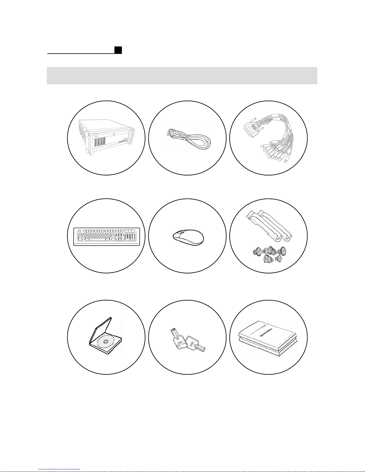
1.1 PRODCUT CONTENTS
DVR
Power cable
MouseKeyboard
Loop Cables
Only MP8916
Handle, Screws
Program CD
Windows OS CD
Note:
The above contents will be changeable with different models
9
Key
Manuals
Page 10
OPERATION MANUAL
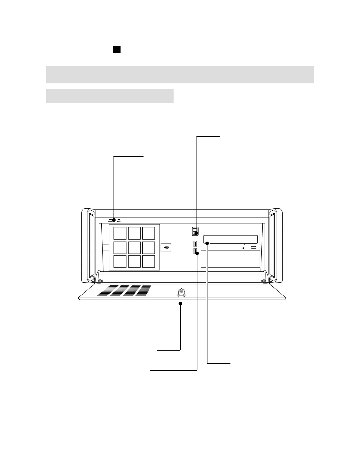
1.2 FRONT LAYOUT
MP 5909/6916/8916
Power LED, HDD LED
Power Switch
10
Lock
USB
Expansion guide
for HDD, CD-RW,
etc
Page 11
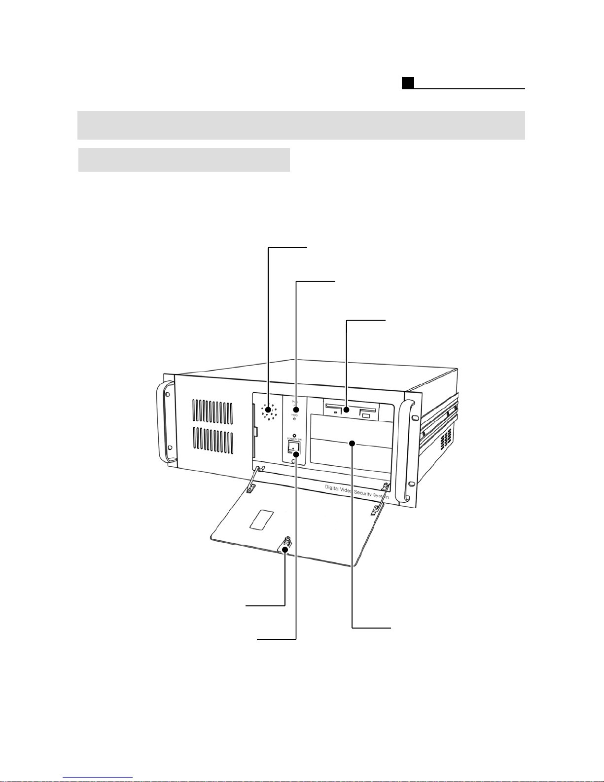
1.2 FRONT LAYOUT
TOPS5909/6916/8916
The system layout may be different from each other model
OPERATION MANUAL
Speaker
Power LED, HDD LED
3 5 inch floppy
disk drive
Power switch
Lock
Expansion guide for
HDD, CD-RW, etc
11
Page 12
OPERATION MANUAL
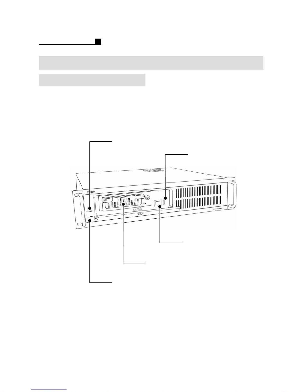
1.2 FRONT LAYOUT
MP5216
The system layout may be different from each other model
HDD LED
USB Port
12
Power switch
Expansion guide for
HDD, CD-RW, etc
Power LED
Page 13
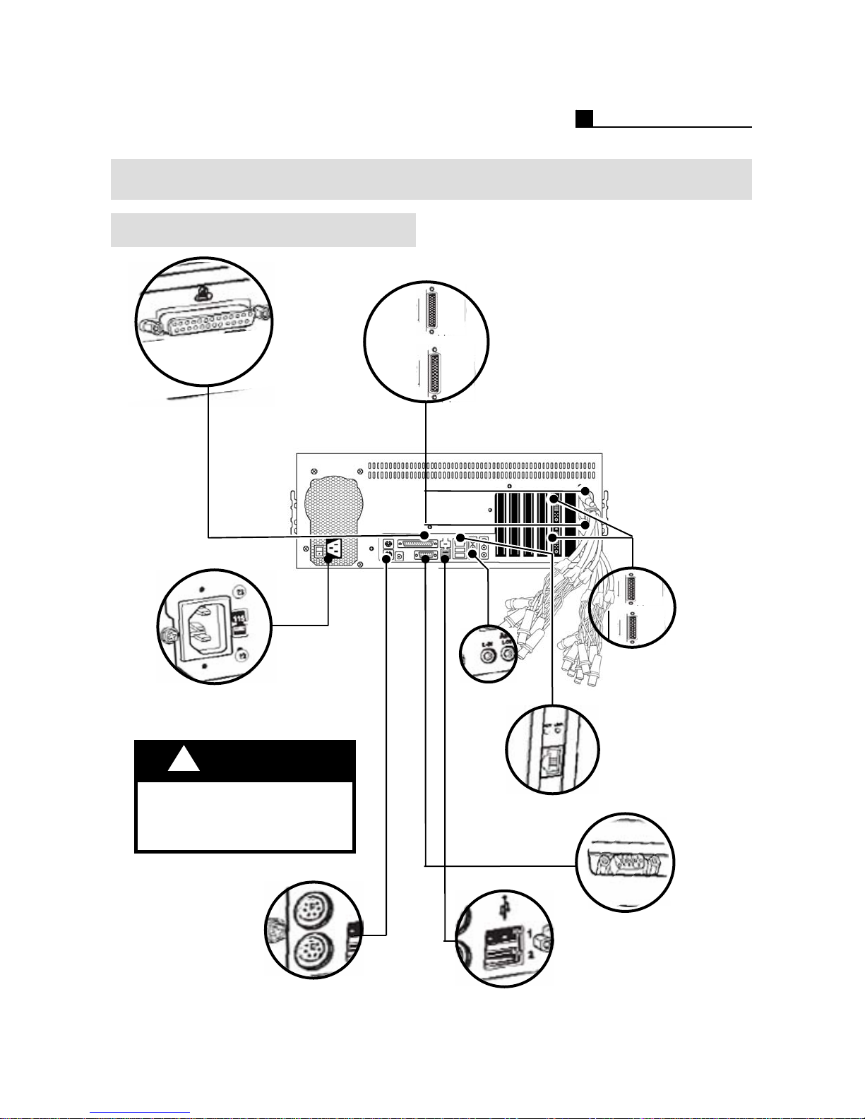
1.3 REAR LAYOUT
MP6916/8916
Printer Port
OPERATION MANUAL
Camera In/MUX Out/SPOT Out
Audio In
AC Power Inlet
115/230 VAC switch
!
Warning
Verify that the voltage is set
correctly for use location.
Mouse/
Keyboard
Alarm Out (Option)
Sensor In (Option)
Audio Out
(Green)
LAN
VGA Out
USB Port
13
Page 14
OPERATION MANUAL
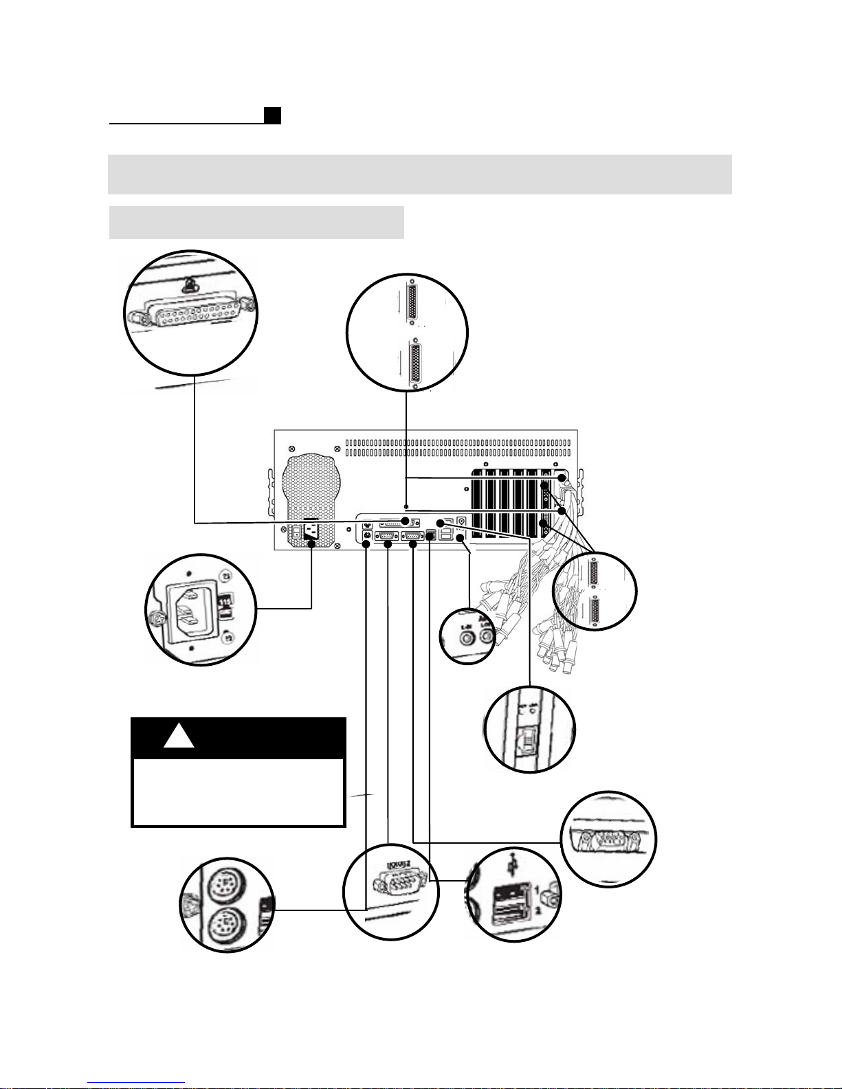
1.3 REAR LAYOUT
MP5916/5909
Printer Port
Camera In/MUX Out/SPOT Out
Audio In
AC Power Inlet
115/230 VAC switch
Verify that the voltage is set
correctly for use location.
14
!
Warning
Keyboard
경고
Mouse/
PAN/TILT Port
Alarm Out (Option)
Sensor In (Option)
Audio Out
(Green)
LAN
VGA Out
USB Port
Page 15
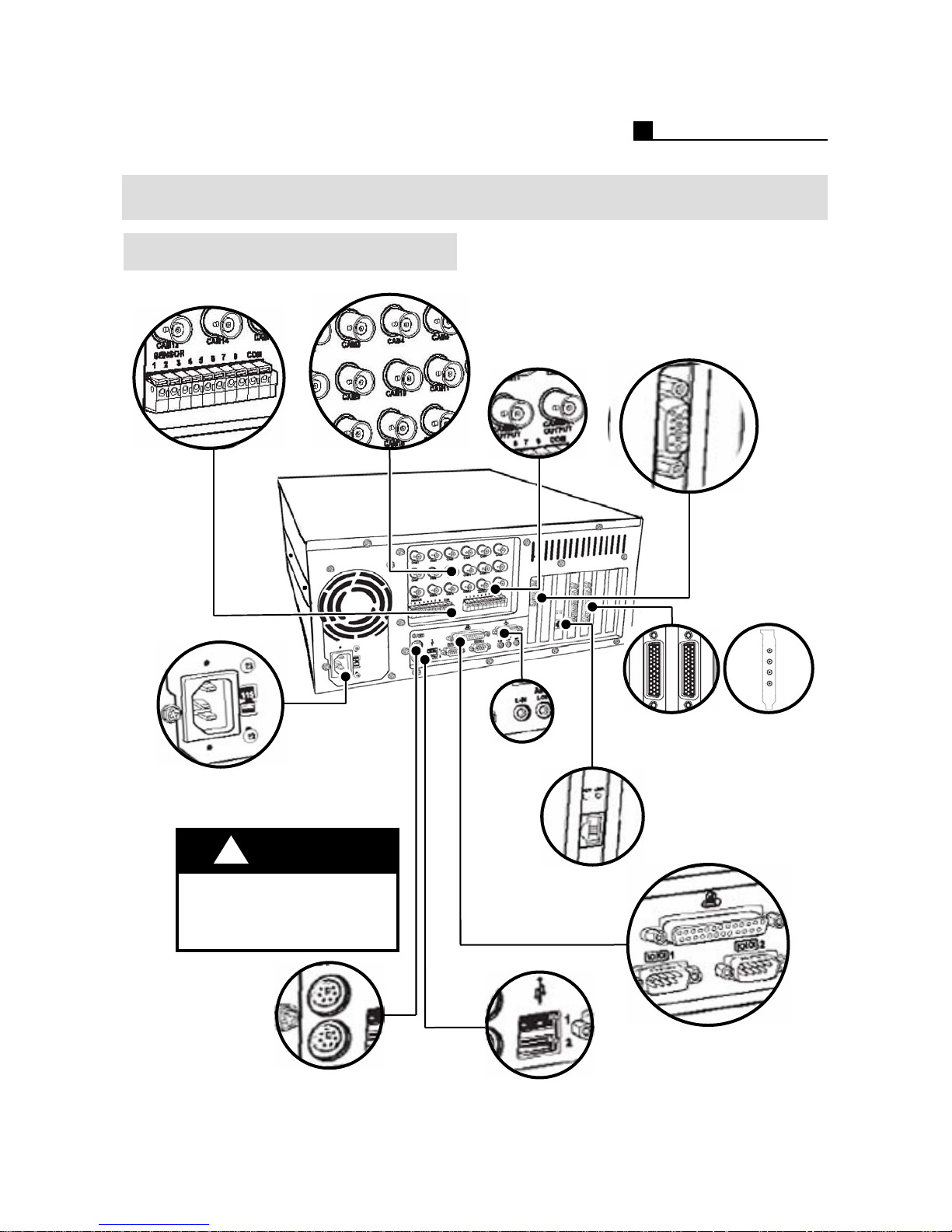
1.3 REAR LAYOUT
MP5909/6916/8916
OPERATION MANUAL
Camera in
Sensor Digital out
AC power inlet
115/230 VAC switch
TV out 1,2
Audio output
Video output
TOPS 8916
Audio input
Camera output
TOPS 5916
TOPS 6916
Audio input
WARNIN
!
Verify that the voltage is
set correctly for user
location
G
Mouse
Keyboard
LAN
LPT1 printer port
Pan/Tilt port 1,2
USB port
15
Page 16

OPERATION MANUAL
2. SURVEILLANCE
2.1 Surveillance
2.2 Preset Setting
2.3 1CH Search
2.4 BACKUP
2.5 How to Log In/Out
2.6 P/W & Rotation
16
Page 17
OPERATION MANUAL
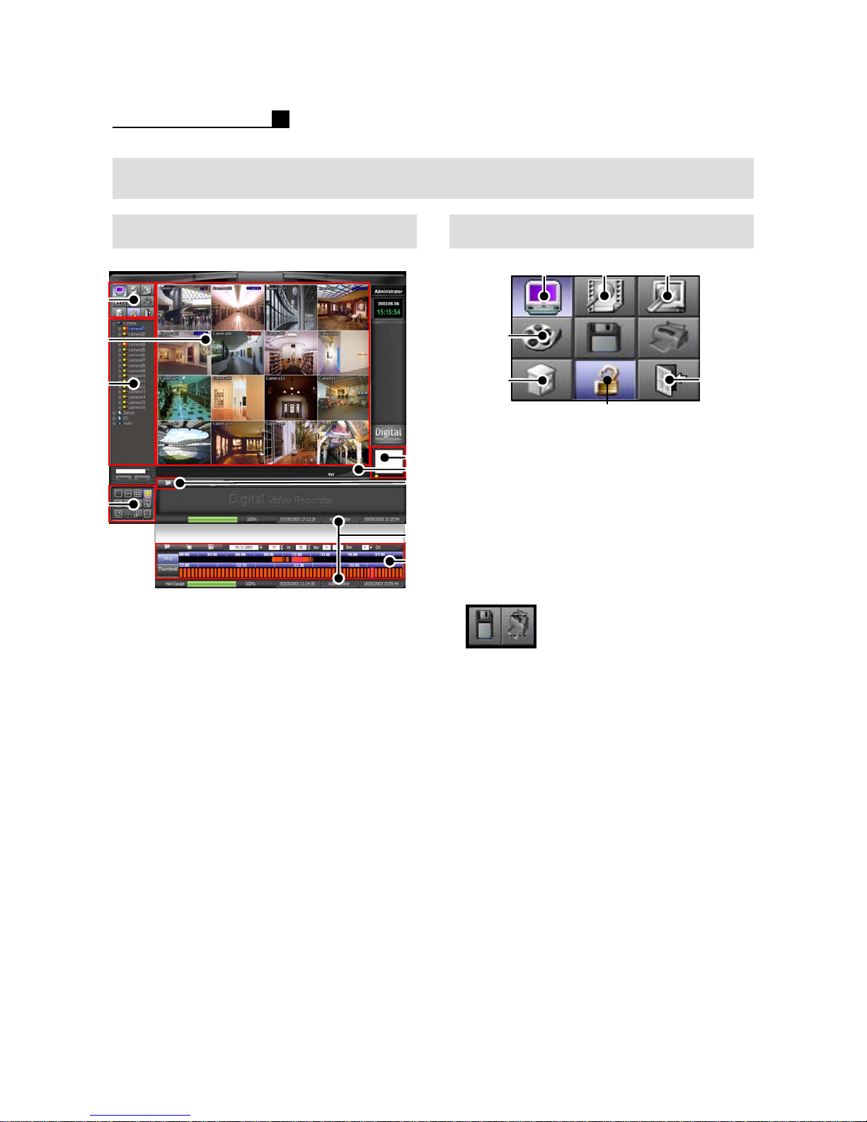
2.1 SURVEILLANCE
Main Mode
①
②
③
④
①Main Menu
② Live View
③ Camera Controller
④ Camera Layout
⑤Digital Zoom
⑥Volume Control
⑦ 1 CH Pop Up Search
⑧Log In User
⑨Map Search
⑤
⑥
⑦
⑧
⑨
Main Menu
①
④
⑤
① Surveillance Mode
② Search Mode
③ Setup Mode
④ Backup Mode
⑤ Password / Rotation
⑥ User Mode (Log In /Out)
⑦Shut Down
NOTE:
Diskette BACKUP and PRINT buttons are only
available on SEARCH MODE.
②③
⑦
⑥
17
Page 18
OPERATION MANUAL
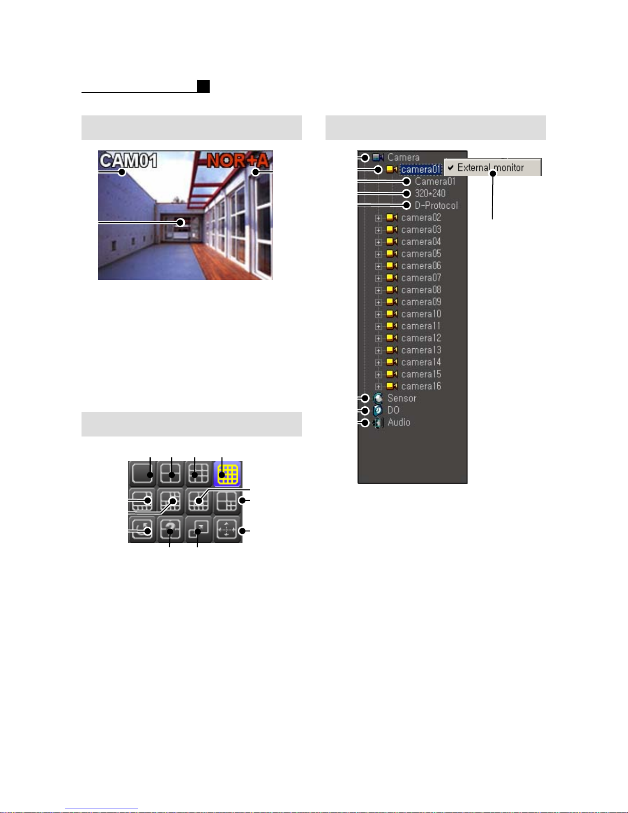
Screen Information Channel Information
①
①
③
① Camera Name
② Recording Status
NOR – Normal Recording
MOT – Motion Recording
SEN – Sensor Recording
MOT+SEN – Motion + Sensor
A – Audio Recording
③ Camera Image
Camera View Layout
②
②
③
④
⑤
⑥
⑦
⑧
⑨
⑤
⑥
⑨
①1 CH
②4 CH
③9 CH
④ 16 CH
⑤1 Main + 7 Sub CH
⑥ 1 Main + 12 Sub CH
⑦2 Main + 8 Sub CH
⑧3 Main + 4 Sub CH
⑨Rotation
⑩ User Selection
⑪Pop UP ON/OFF
⑫ Full Screen
18
①
②
⑩
③④
⑪
⑦
⑧
⑫
① Camera Group
② Camera No.1
③ Camera Name
④ Camera Resolution
⑤ Camera Protocol
⑥ Sensor Group
⑦ D/O Group (Alarm Out)
⑧ Audio Group
⑨ External Monitor
NOTE:
Sub menu is available when right mouse
click each CH like “External Monitor” or
“ON/ OFF”
Page 19
OPERATION MANUAL
User Selection
① Click “USER SELECTION” button
② Drag a cam from “CAMERA
INFORMATION” and drop it on the
“LIVE VIEW”
Note:
The below is the example of “User
Selection”.
Cam1. Cam2.
Cam3. Cam4.
Cam2. Cam1.
Cam4. Cam3.
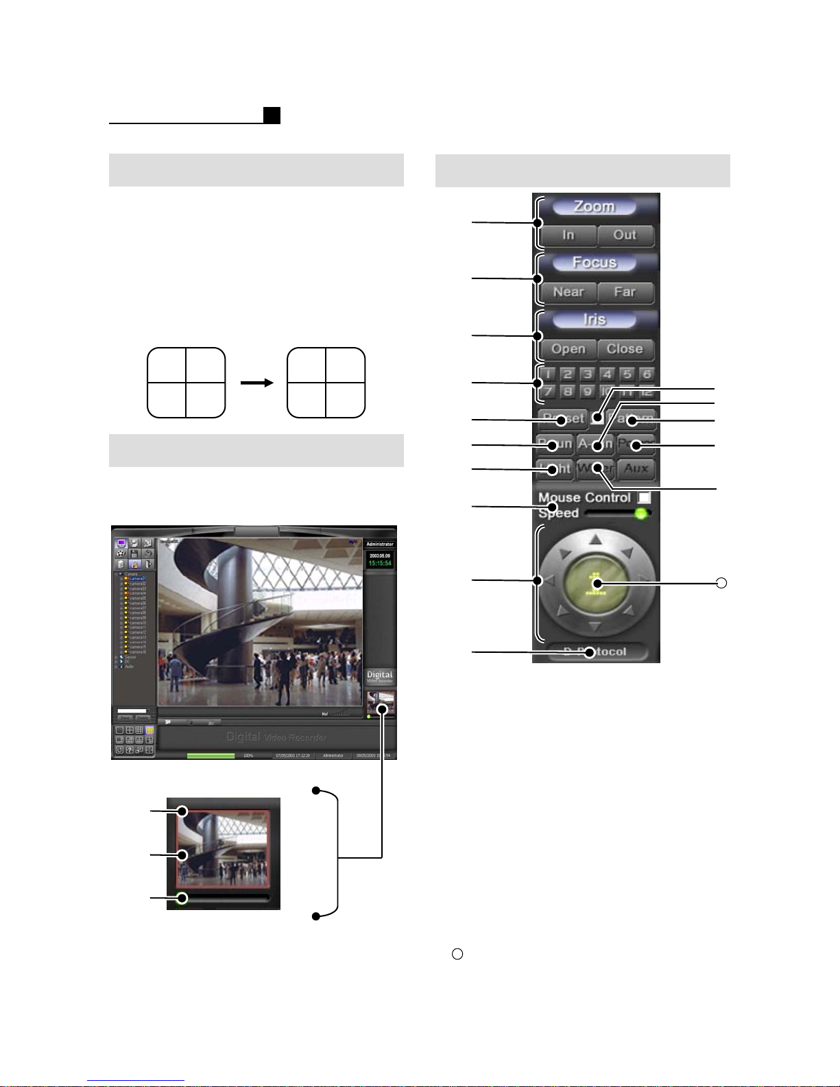
Digital Zoom
Digital Zoom is only available at 1 CH
layout.
MOT
MOT
PAN/TILT
①
②
③
④
⑤
⑥
⑦
⑧
⑪
⑫
⑬
⑭
⑮
①
②
③
①Digital Zoom Box (RED)
② Panning View
③Digital Zoom Control Bar
19
⑨
⑩
①Zoom
②Focus
③Iris
④Preset No.
⑤Preset
⑥P-Run
⑦Light
⑧ Mouse Control Speed
⑨PTZ Direction
⑩ Protocol Information
⑪ Preset/Pattern Save
⑫ A-Run: Auto moving to the Position
⑬ Pattern: Auto moving according to
Pattern Set
⑭ Power: Turn On/Off Camera
⑮Wiper
16
Camera No.
16
Page 20
OPERATION MANUAL
2.2 PRESET SETTING
How to set Preset
① Select CH No.
② Select “Preset”
③ Tick “Preset Save”
④ Move the camera direction
⑤ Select a “Preset No.” to save
⑥ Click “P-Run’ to move the saved Preset
Note:
PTZ Control is only available at 1 CH
layout.
PTZ MENU is displayed when PTZ camera
is selected.
How to delete Preset
① Select CH No.
② Select “Preset”
③ Select a “Preset No.” to delete
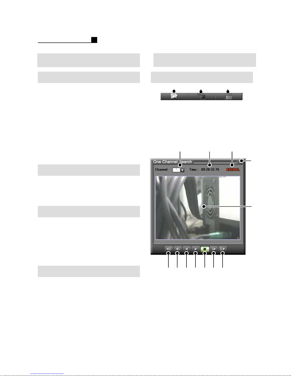
2.3 1CH SEARCH
1CH Search
①
① 1CH Search
② Smart Search (Object Search)
③Map Search
Note:
1 CH Search is available at Surveillance
Mode
① ② ③
②③
④
How to set Pattern
① Select CH No.
② Select “Pattern”
③ Tick “Pattern Save”
④ Move the camera direction
⑤ Deselect “Pattern Save”
⑥ Moving between ③ and ⑤
How to use Mouse Control
① Select CH No.
② Tick “Mouse Control”
③ Adjust “Speed”
④ Move the direction with mouse
20
⑤
⑥ ⑦ ⑧ ⑨ ⑩ ⑪ ⑫
①CH No.
②Rec. Time
③ Record Type
④Close 1 CH Search
⑤ Recorded Image
⑥First Image
⑦Previous Image
⑧Reverse
⑨Playback
⑩Stop
⑪Next Image
⑫Last Image
Page 21
OPERATION MANUAL
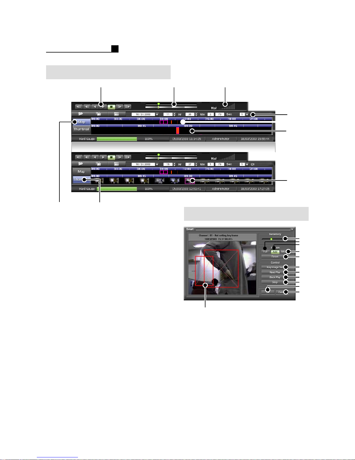
Playback
①②③
④
⑤
⑥
⑨
⑦
①Play Control
② Playback Speed
③Audio Volume
④ Year/Month/Hour/Min/CH Search
⑤ 24 Hour Map
⑥ 1 Hour map
⑦Hide Thumbnail Map
⑧Show Thumbnail Map
⑨ Show image every 5 minutes for 1 hour
⑧
Smart Search
①
①Detection Area
② Sensitivity
③ Full Screen Detection
④Specific Area
⑤ Move: Move the Area
⑥ Reset Area
⑦ Set Area
⑧Playback
⑨Reverse
⑩Stop
⑪ Confirm the time and Close
⑫ Close Smart Search
②
③
⑤
⑥
⑦
⑧
⑨
⑩
⑪
⑫
④
21
Page 22
OPERATION MANUAL
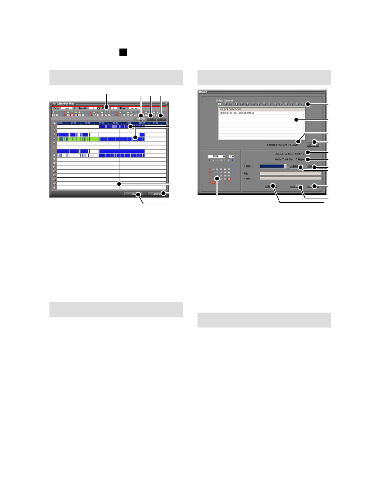
Calendar Search
①
① Calendar (Year/Month/Date/Time)
②Detailed Map
③Previous Time
④Next Time
⑤ Record Status
NOR-Red, MOT-Blue, SEN-Green
⑥ Selection Line
⑦Close
⑧ Playback the selected time
⑨ Detailed view for record map
② ③ ④
⑤
⑥
⑦
⑧
2.4 BACKUP (MP SERIES)
①
①Calendar
② Camera No.
③ List recorded data
④ Selected recorded data
⑤Reset
⑥ Free space of Media
⑦ Total space of Media
⑧Format
⑨Eject
⑩Close
⑪Hide
⑫ Start / Stop
②
③
④
⑤
⑥
⑦
⑧
⑨
⑩
⑪
⑫
Smart Search
① Select 1 CH Layout
② Select Smart Search
③Click “ADD”
④ Set Area on the screen
⑤ Adjust “Sensitivity”
⑥ Select “Key Image Set”
⑦ Select “Next Play”
22
How to Backup
① Select “Backup” Mode
②Insert Media
③ Select the date
④ Select the drive
⑤ Select Camera No.
⑥ Select data
⑦ Press “Start”
NOTE:
Format must be done before BACKUP.
NOTE:
Tick “Viewer Copy” for backup viewer
save with backup data.
Page 23
OPERATION MANUAL
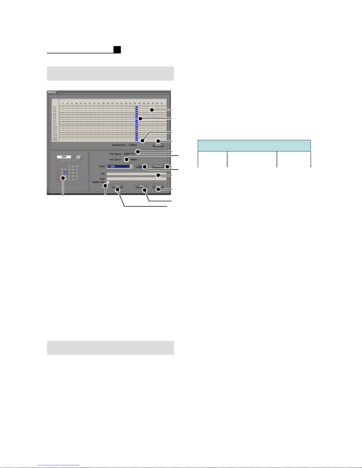
Backup (TOPS Series)
①
①Calendar
② Data Map
③ Recorded Data (Blue)
④ Selected Size
⑤Reset
⑥ Free Space of Media
⑦ Total space of Media
⑧Format
⑨Eject
⑩ Backup Status
⑪Close
⑫Hide
⑬Start/Stop
⑭ Backup Viewer Copy
⑭
②
③
④
⑤
⑥
⑧
⑩
⑪
⑫
⑬
NOTE:
The backup time can be longer than the
selected time.
Ex) If user choose the backup time from
7:00 to 8:00, DVR will backup the data
6:45 to 8:45. It’s because DVR backup
the data on 64MB DB base.
DB file of DVR
DB file of DVR
64MB
64MB
64MB
⑦
⑨
6:45 7:00 8:00
6:45 7:00 8:00
6:45 7:00 8:00
8:45
8:45
NOTE:
Format must be done before BACKUP.
How to Backup
① Select “Backup” Mode
②Insert Media
③ Select the date
④ Select the drive
⑤ Select data
⑥ Press “Start”
NOTE:
Tick “Viewer Copy” for backup viewer
save with backup data.
23
Page 24
OPERATION MANUAL
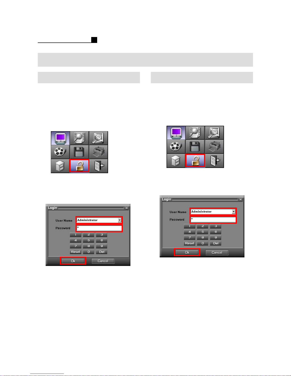
2.5 HOW TO LOG IN / OUT
How to Log In How to Log Out
① Go to User Mode
② Select user name
③Type Password
④ Press “OK”
1. Go to User Mode.
Click the User button in red.
2. Select User name.
3. Type Password.
Default P/W is “0”.
4. Press “OK”.
① Go to User Mode
②Type Password
③ Press “OK”
1. Go to User Mode.
Click the User button in red.
2. Type Password.
Default P/W is “0”.
3. Press “OK”.
24
Page 25
OPERATION MANUAL
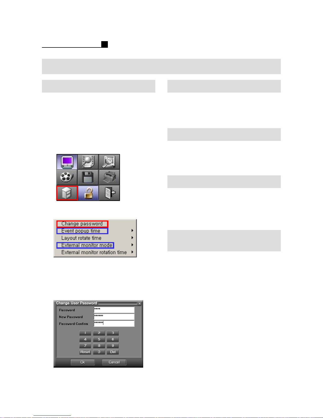
2.6 PASSWORD / ROTATION
How to change P/W How to set Rotation Time
① Go to PASWORD / ROTATE Mode
② Select “Change Password”
③Type Password
Default P/W is “0”.
④ Press “OK”
1. Go to PASSWORD Mode.
Click the PASSWORD button in red.
2. Select “Change Password”.
① Go to PASSWORD / ROTATE Mode
② Select “Layout Rotate Time”
③ Select the duration time
How to set Event Pop up Time
① Go to PASSWORD / ROTATE Mode
② Select “Event Popup Time”
③ Select the duration time
How to set External Monitor
① Go to PASSWORD / ROTATE Mode
② Select “External Monitor”
③ Select “Fixed”, “Spot” and
“Event Spot” mode
How to set External Monitor
Rotation Time
Note:
Function in blue is not available with TOPS
Series.
3. Change the Password.
25
① Go to PASSWORD / ROTATE Mode
② Select “External Monitor Rotation
Time”
③ Select the time
Page 26

OPERATION MANUAL
3. SEARCH
3.1 Search
3.2 Panorama Search
3.3 AVI, JPG, BMP Save
26
Page 27
OPERATION MANUAL
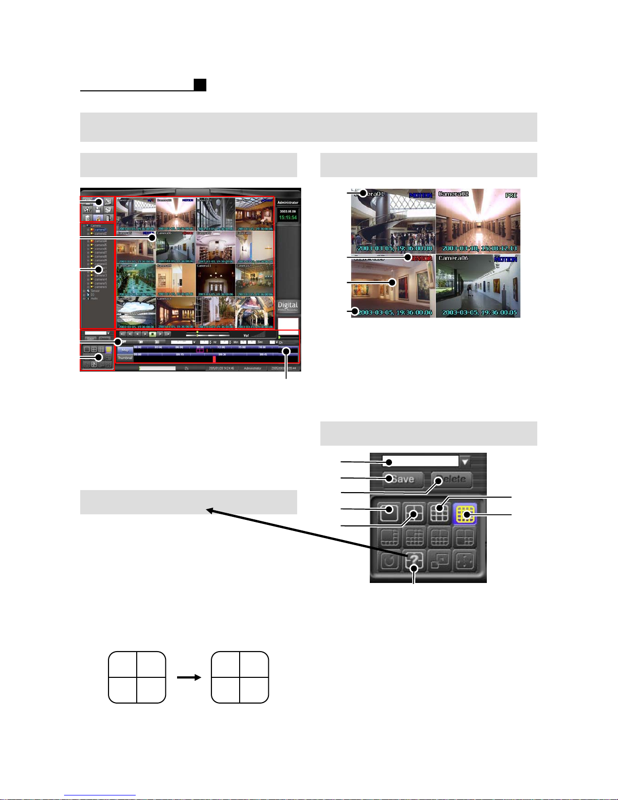
3.1 SEARCH
Main Mode Search Screen
①
②
②
③
④
⑤
① Search Mode
② Search Screen
③ Camera Information
④ Panorama Search Information
⑤ Camera Layout
⑥ Map & Thumbnail View
User Selection
① Click “USER SELECTION” button
② Drag a cam from “CAMERA
INFORMATION” and drop it on the
“SEARCH SCREEN”
⑥
①
②
③
④
① Camera Name
② Recorded Status
③ Playback Image
④ Recorded Time
Camera Layout
①
②
③
④
⑤
⑥
⑦
Note:
The search layout will be changeable.
The below is the example of “USER
SELECTION”.
Cam1. Cam2.
Cam3. Cam4.
27
Cam2. Cam1.
Cam4. Cam3.
⑧
① User Layout Name
② Save User Layout
③ Delete User Layout
④1CH
⑤4CH
⑥9CH
⑦16CH
⑧ User Selection
Page 28
OPERATION MANUAL
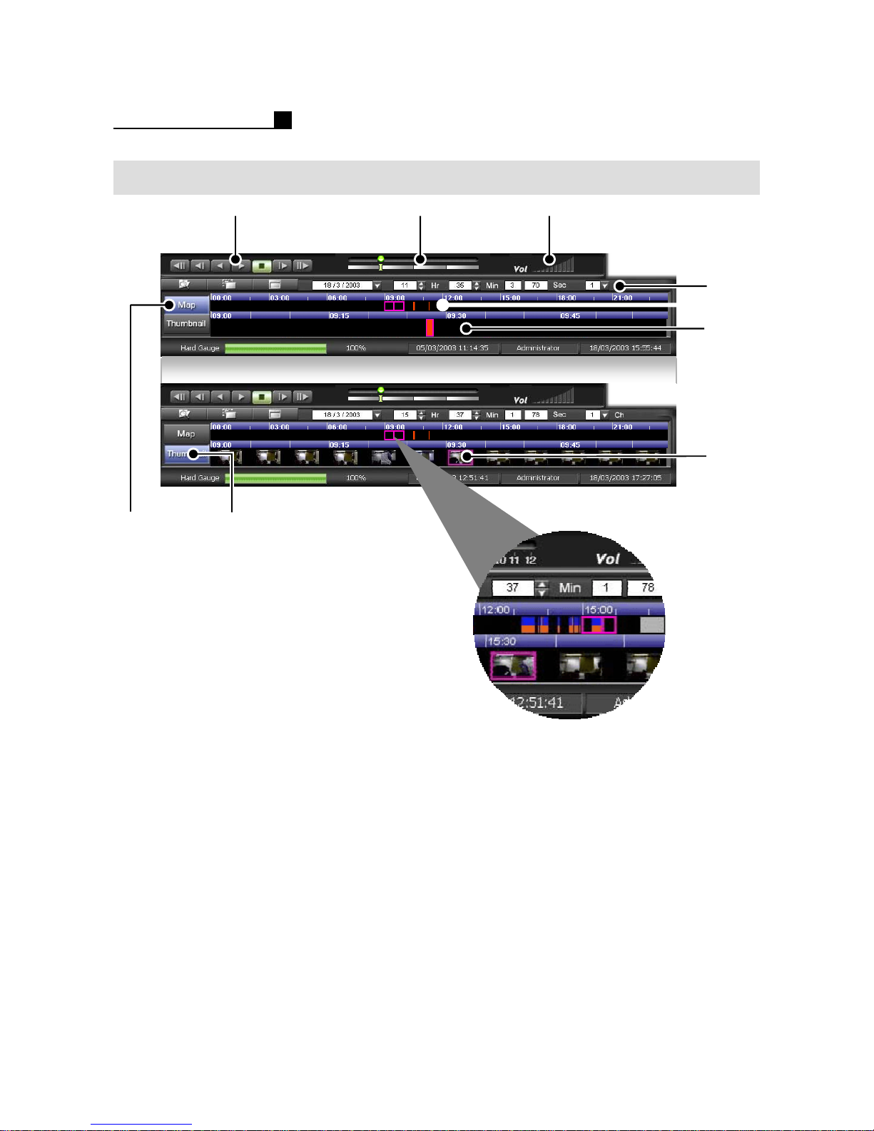
Playback
①②③
④
⑤
⑥
⑨
⑦
①Play Control
② Playback Speed
③Audio Volume
④ Year/Month/Hour/Min/CH Search
⑤ 24 Hour Map
⑥ 1 Hour map
⑦Hide Thumbnail Map
⑧Show Thumbnail Map
⑨ Show image every 5 minutes for 1 Hour
⑧
28
Page 29
OPERATION MANUAL
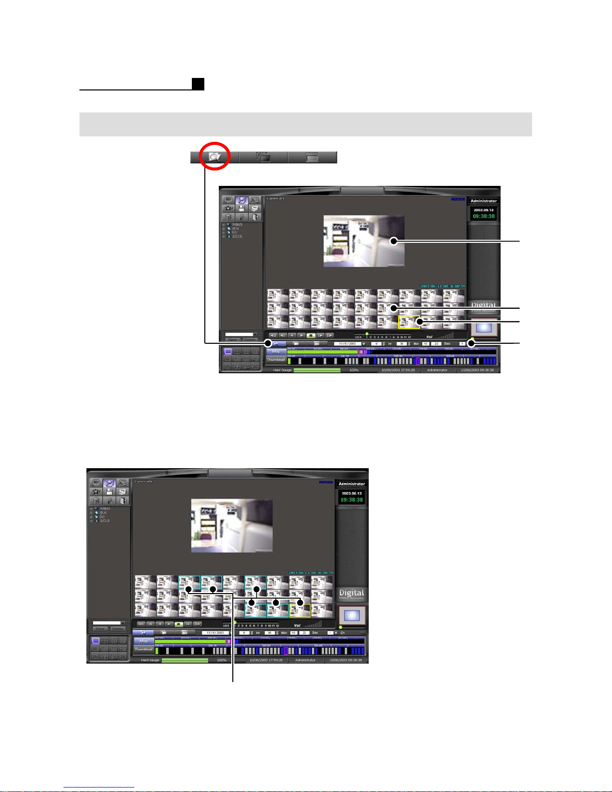
3.2 PANORAMA SEARCH
①
②
③
④
① 1CH Search Screen
② Panorama Screen
③ Playing Screen
④ Time/Camera Selection
Note:
Before saving AVI, JPG, BMP, user should
select the images like the below.
① Selected Screen
①
29
Page 30
OPERATION MANUAL
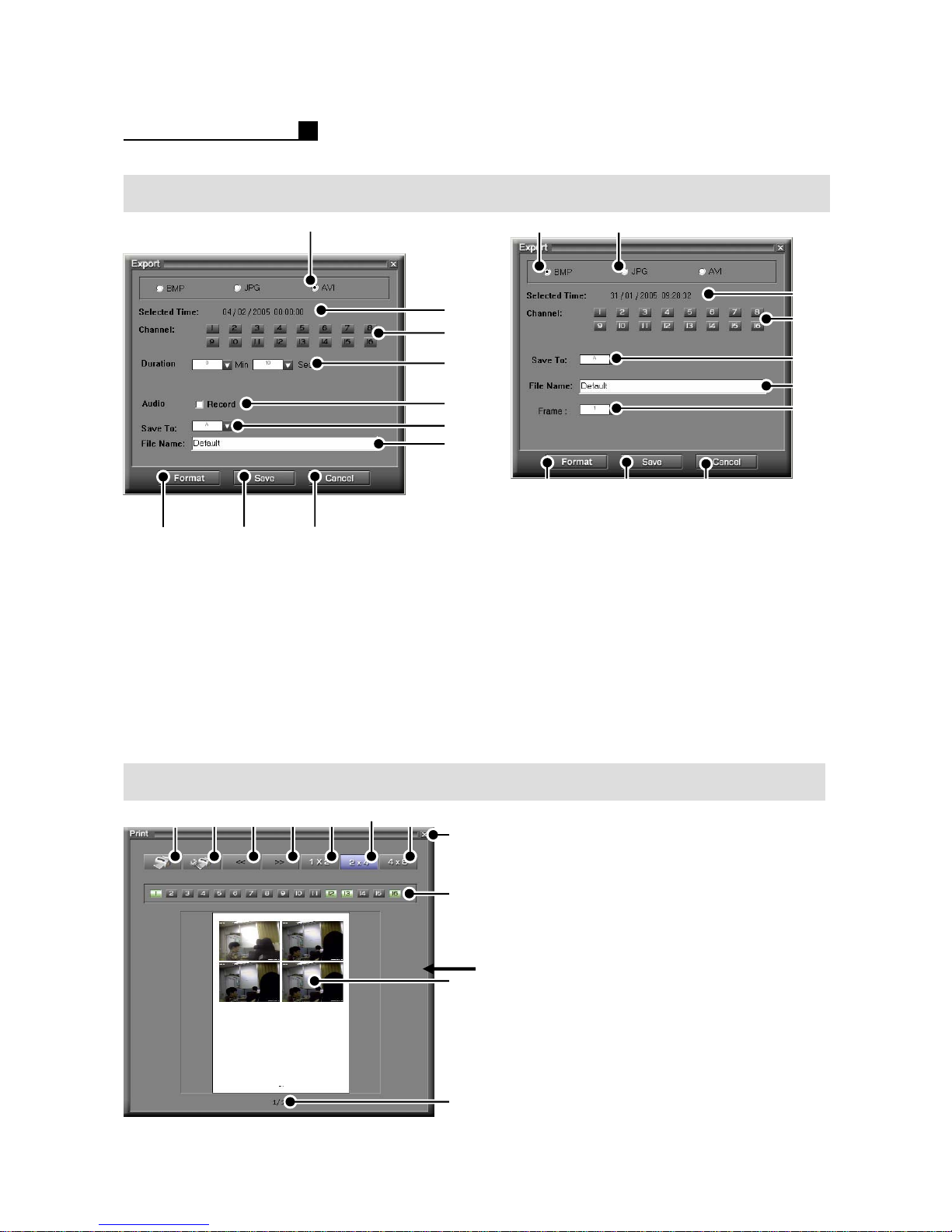
3.3 AVI, JPG, BMP Save
⑧
①AVI Save
② Selected Time
③ Camera No.
④AVI Duration
⑤ Audio Record
⑥ Drive Selection
⑦File Name
⑧Format Media
⑨Save
⑩Cancel
⑨
①
⑩
②
③
④
⑤
⑥
⑦
①
⑧
①BMP Save
②JPG Save
③ Selected Time
④ Camera No.
⑤ Drive Selection
⑥File Name
⑦ Count No.
⑧Format Media
⑨Save
⑩Cancel
②
⑨
③
④
⑤
⑥
⑦
⑩
Print
①⑪② ③ ④ ⑤ ⑥ ⑦
30
⑧
⑨
⑩
①Print
② Printer Setup
③Previous Print Image
④Next Print Image
⑤Layout 1X2
⑥ Layout 2X4
⑦Layout 4X8
⑧Close
⑨ Camera Selection
⑩Preview
⑪Page No.
NOTE:
Printer Drive should be installed before
printing the image.
And make sure that printer is connected to
DVR and power is ON.
Page 31

OPERATION MANUAL
4. CONFIGURATION
Camera/Sensor
Schedule
Sensor
Password
Backup
Network
31
Page 32
OPERATION MANUAL
4. SETUP (MPII SERIES)
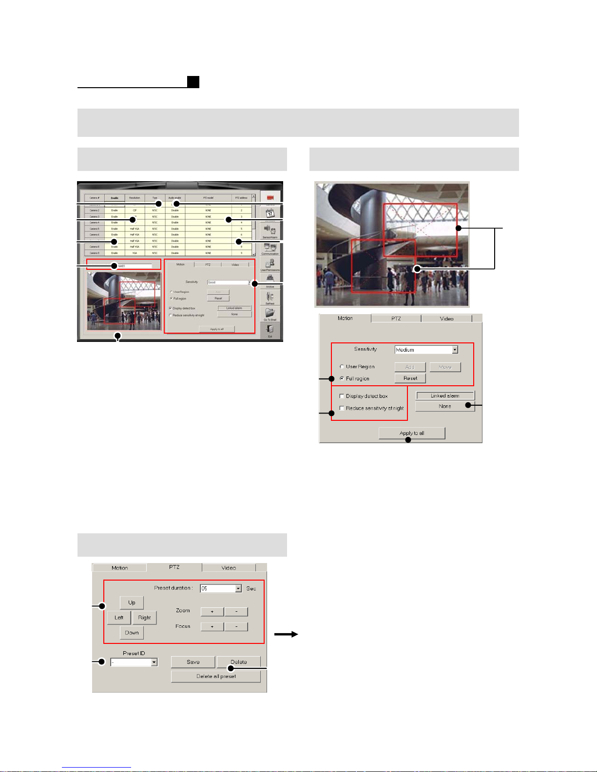
4.1 CAMERA /SENSOR Motion Area
①
②
③
⑦
⑧
①NTSC/PAL
②Resolution (CIF/HALF VGA/VGA)
③ Camera On/Off
④Audio On/Of
⑤ PTZ Protocol
⑥ PTZ Address
⑦ Camera Name
⑧ Motion Setting Area
⑨ Motion, PTZ, Video (Color)
PTZ
④
⑤
⑥
⑨
②
③
⑤
① User Setting Area
② User Defined – Small Area
Full Region –Full Area
③ Display Detection Box
Reduce Sensitivity at night
④ Motion-Alarm Setting
⑤ Apply to all cameras
①
④
①
②
32
③
①Direction, Zoom, Focus
Preset Duration
②Preset ID
③ Preset Save, Preset Delete.
Delete all Presets
Page 33
⑤
⑧
⑦
⑥
①
②
OPERATION MANUAL
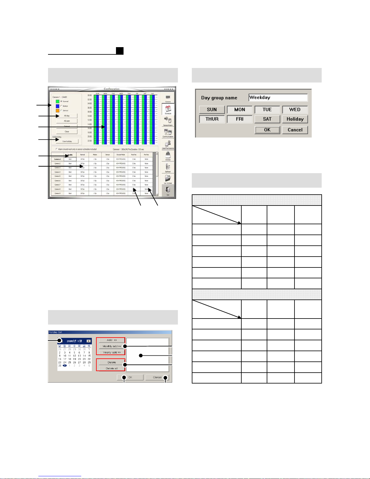
4.2 SCHEDULE Schedule Group Setting
① Click “Weekend”, “Weekday”, “Holiday”
for group setting.
② Select days for the group of weekday.
PRE Duration Information
480FPS (Model 8916) Duration-Sec.
①Quality (5 Steps)
② Recording Speed
③ Post Recording (10Sec~5Min)
④ Pre Recording(4 Steps)
⑤ Recording Type Selection
⑥ Weekday, Weekend, Holiday
⑦ Schedule Setting Area
⑧Default
Clear –Delete a camera schedule
All Cam –Apply a schedule to all
Cameras
All Day –Apply a schedule to all days
⑨Add Holiday
③④
FPS
240FPS (Model 6916) Duration-Sec.
Duration
2 1 Step 1 (MAX)
4 2 Step 2
6432Step 6 (MIN)
LongMiddleShort
3
6
128 4Step 3
2416 8Step 4
4832 16 Step 5
96
Holiday
①
⑤
① Previous/Next Month
② Add, Monthly Add, Yearly Add
③ Added Holiday List Box
④ Delete(1 time), Delete all holidays
⑤Save & Exit
⑥Exit
33
⑥
②
③
④
Duration
FPS
Step 1 (MAX)
Step 2
Step 6 (MIN)
2
4
8
16
32
64
MiddleShort
4
8
128
Long
6
12
24 16 Step 3
48 32 Step 4
96 64 Step 5
192
Page 34
OPERATION MANUAL
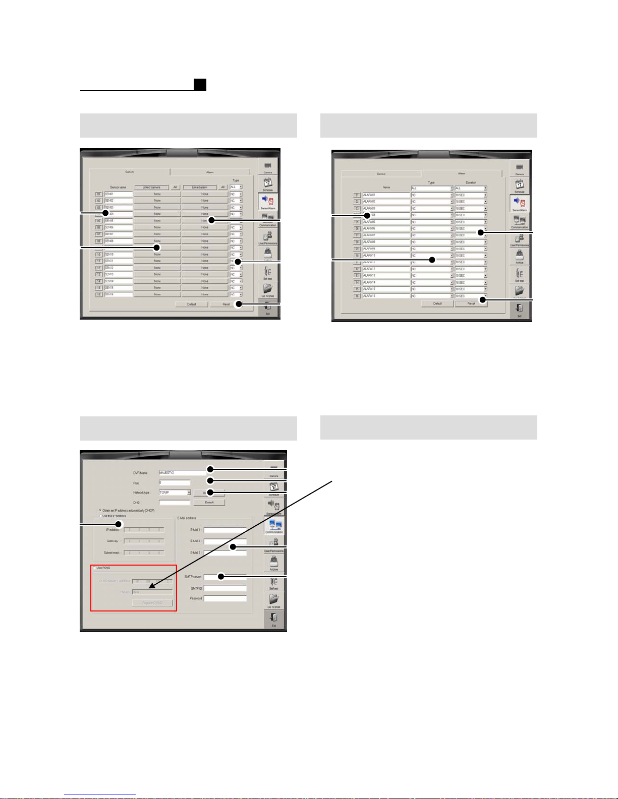
4.3 SENSOR Alarm
①
②
① Sensor Name
② Linked Camera Selection
③ Linked Alarm Selection
④ Sensor Type (N/C, N/O)
⑤Default
⑥Reset
Network
③
④
⑤
①
②
③
①
③
②
④
① Alarm Name
②Alarm Type (N/C, N/O)
③ Alarm Duration
(1 time, 1Sec~10Min, Continue)
④Default
⑤Reset
How to set PDNS
①Tick “Use PDNS”
②Type “DVR ID”
③ Press “Register DVR ID”
④
①DVR Name
② Network Port
③ Network Type (TCP/IP,MODEM)
④ DHCP/IP Setting
⑤ E-mail list for emergency transmission.
⑥ SMTP Server
34
Note:
If the DVR ID is already used on other
DVR, it will show warning message.
⑤
⑥
Page 35
OPERATION MANUAL
①
②
①
②
③
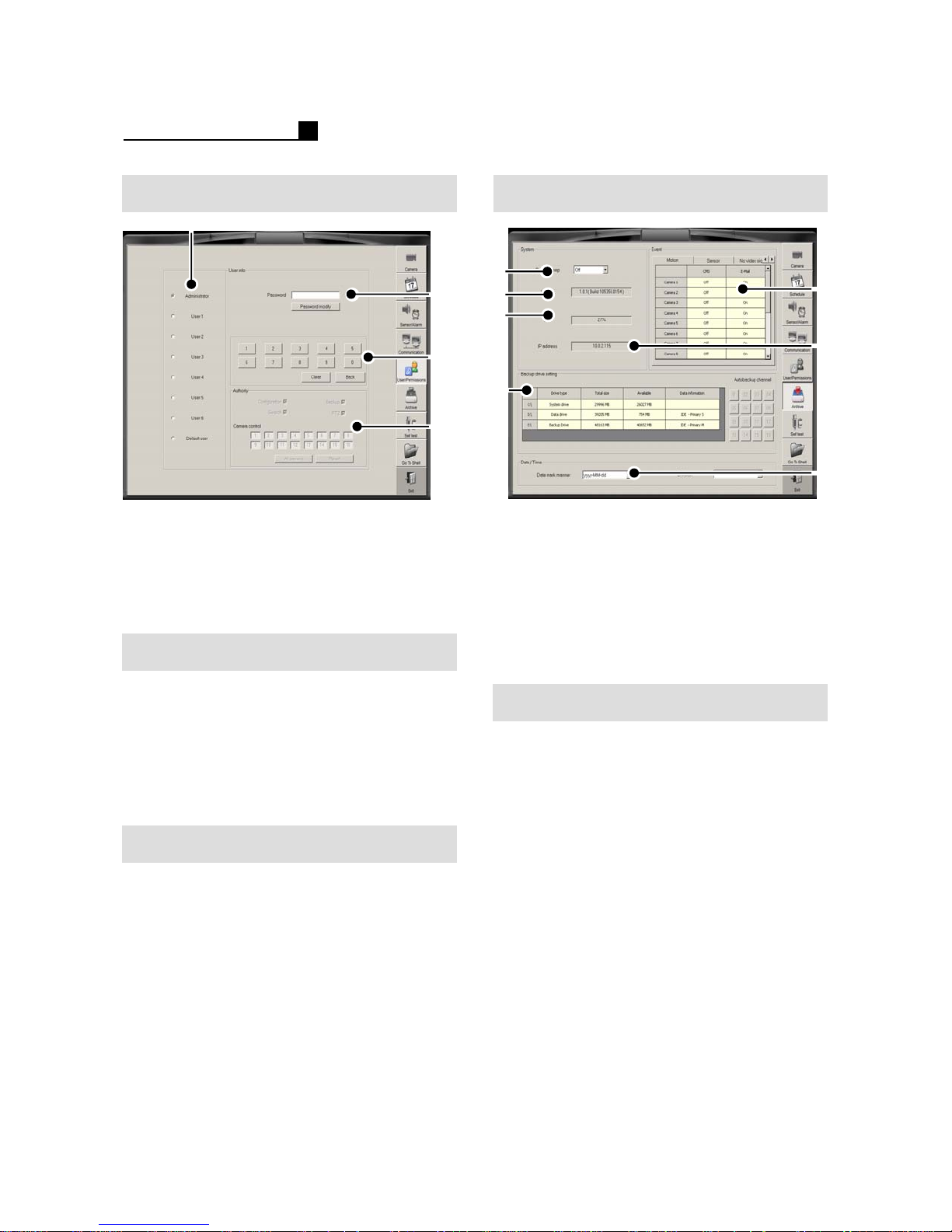
ArchiveUser/Password
⑤
① User Selection
② Password Configuration
③ Password No.
④ Configuration, Backup, Search, PTZ,
Camera Selection
Password Change
① Choose user
②Input P/W
③ Click “Password Modify” button
④ Input New P/W and confirm the P/W
⑤ E-mail list for emergency transmission.
⑥ SMTP Server
③
④
⑥
④
⑦
① System Beep
②S/W Version
③ CPU Usage Status
④ Backup Drive Setting
⑤ Event Transmission Setting
(Motion, Sensor, No Video Signal)
⑥ IP Address
⑦DATE/TIME Format
Backup Drive Setting
① Go to Backup Drive Setting
② Choose a drive
Ex) D:, E:, F:
③ Change the drive for Backup drive
④Save & Exit
User Authority Change
① Choose user
② Change “Authority” like Configuration,
Backup, Search, PTZ, Camera
③Save & Exit
35
Page 36
OPERATION MANUAL
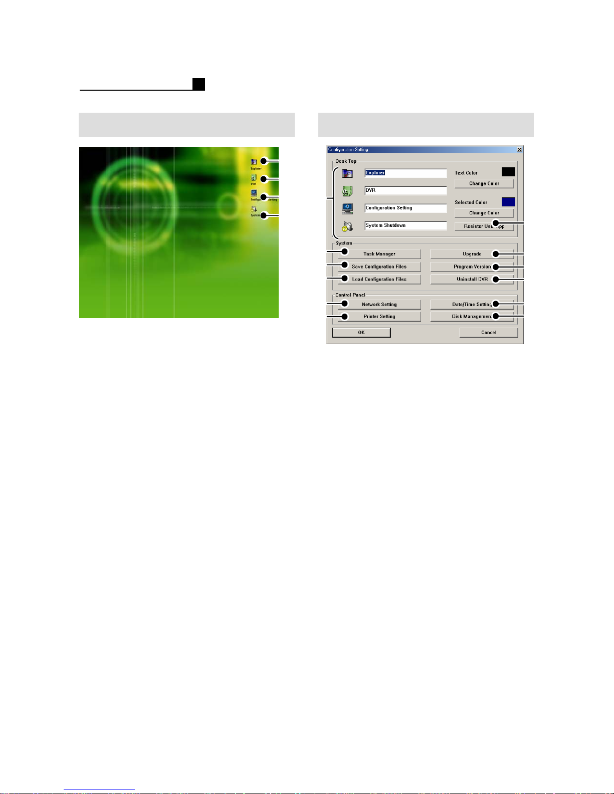
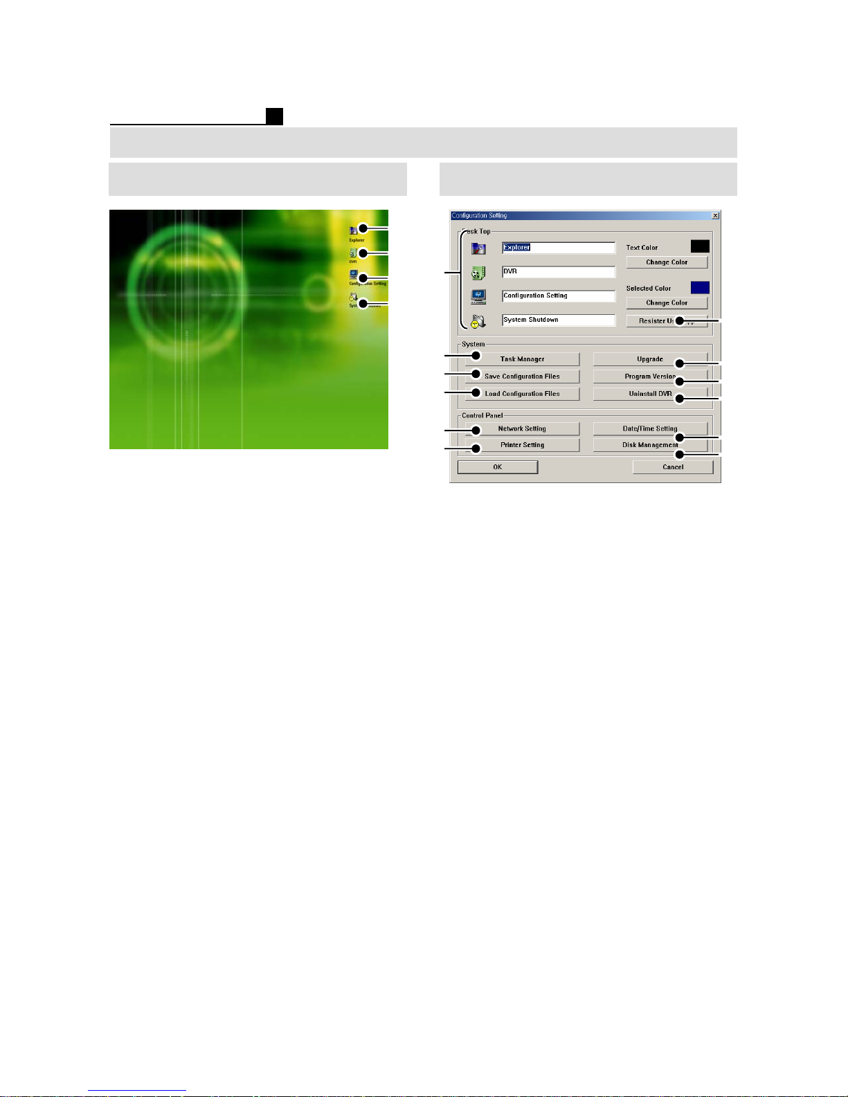
SHELL MODE
① Windows Explorer
② Go to DVR Mode
③ Configuration Setting
(Color, Date, Network, Printer)
④DVR Shut down
①
②
③
④
Configuration Setting
①
②
③
④
⑨
⑩
①Icon Name
② Windows Task Manager
③ Save Configuration Files
④ Load Configuration Files
⑤ Register User
⑥ Upgrade DVR
⑦Program Version
⑧ Uninstall DVR Program
⑨ Network Setting
⑩ Printer Setting
⑪ DATE/TIME Setting
⑫DISK Management
⑤
⑥
⑦
⑧
⑪
⑫
36
Page 37
OPERATION MANUAL
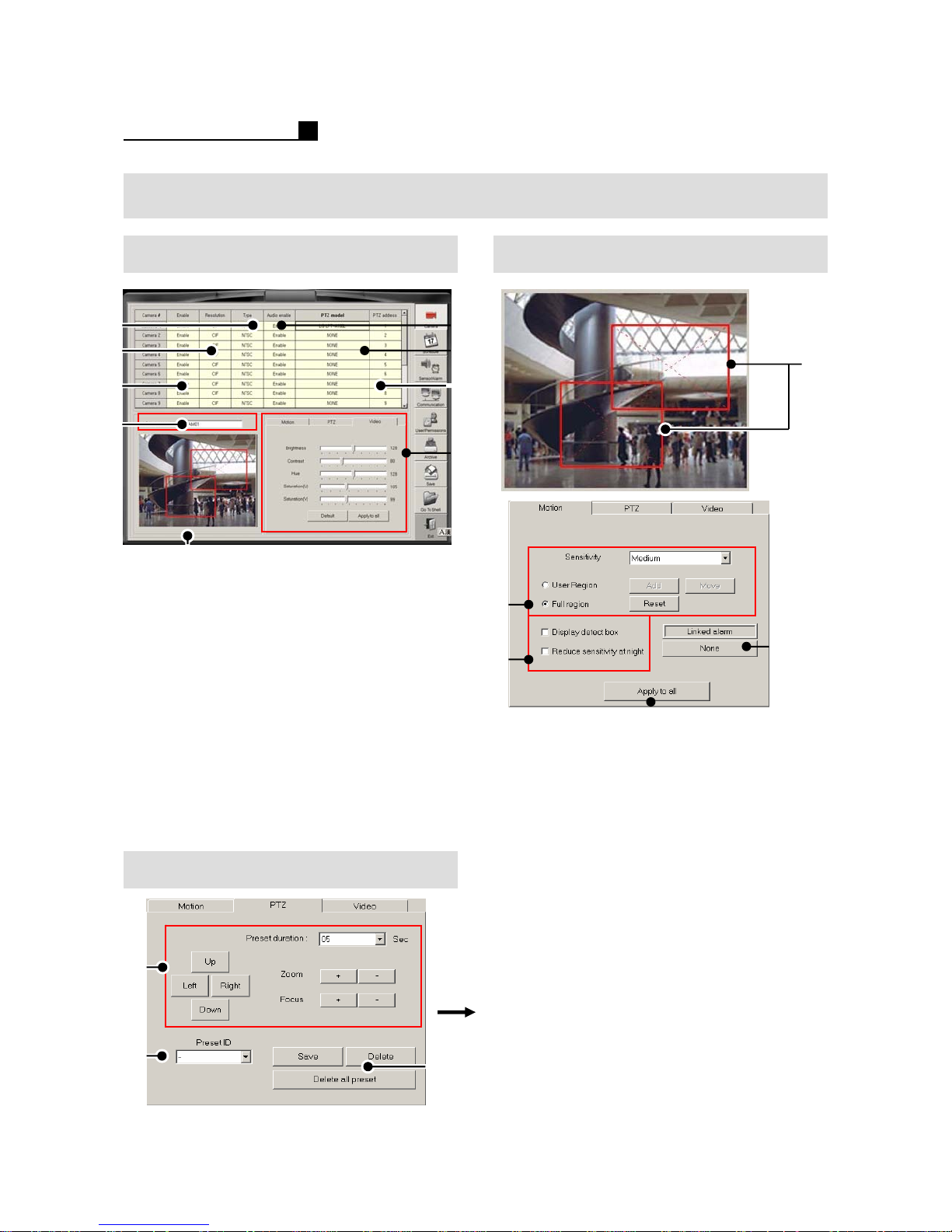
4. SETUP (MP SERIES)
Camera /Sensor Motion Area
①
②
③
⑦
⑧
①NTSC/PAL
②Resolution (CIF/HALF VGA/VGA)
③ Camera On/Off
④Audio On/Off
⑤ PTZ Protocol
⑥ PTZ Address
⑦ Camera Name
⑧ Motion Setting Area
⑨ Motion, PTZ (Event Tracking),
Video (Color)
PTZ
④
⑤
⑥
⑨
②
③
⑤
① User Setting Area
② User Defined – Small Area
Full Region –Full Area
③ Display Detection Box
Reduce Sensitivity at night
④ Motion-Alarm Setting
⑤ Apply to all cameras
①
④
①
②
37
③
①Direction, Zoom, Focus
Preset Duration
②Preset ID
③ Preset Save, Preset Delete.
Delete all Presets
Page 38
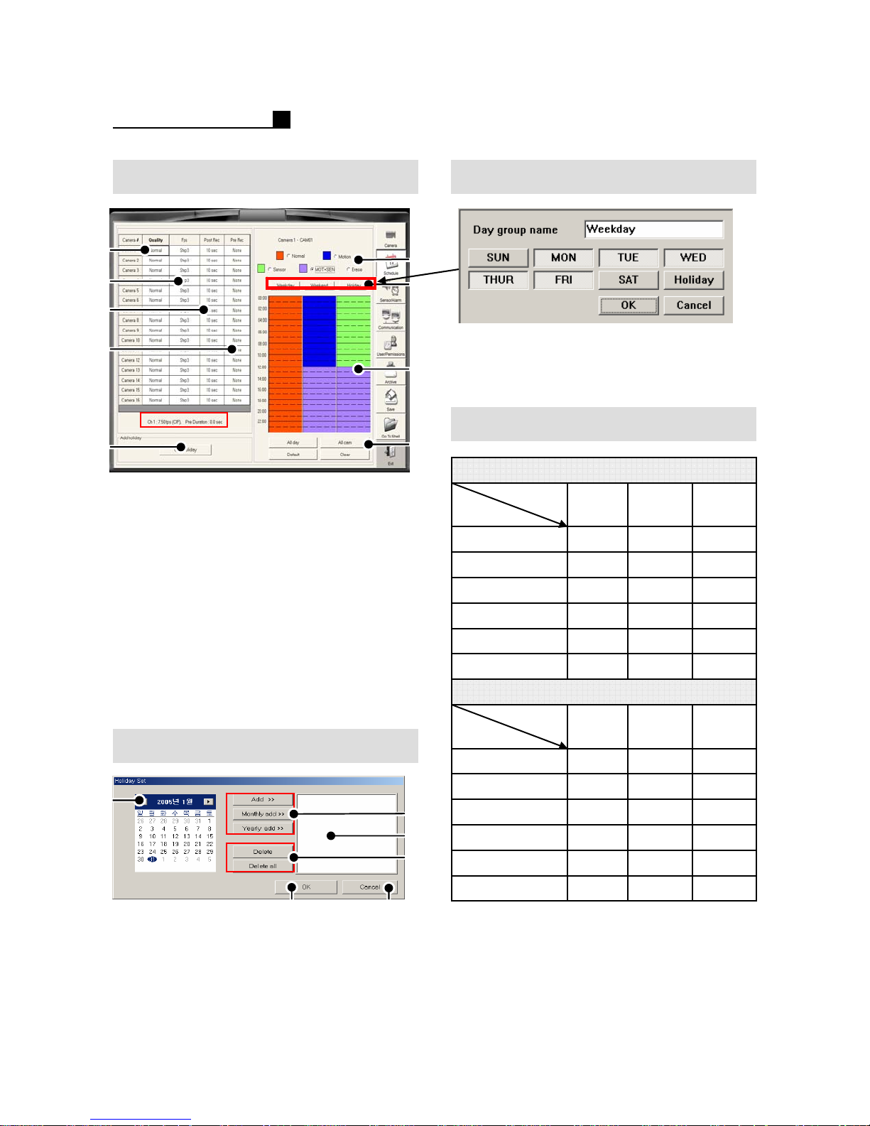
OPERATION MANUAL
Schedule Schedule Group Setting
①
②
③
④
⑨
①Quality (5 Steps)
② Recording Speed
③ Post Recording (10Sec~5Min)
④ Pre Recording(4 Steps)
⑤ Recording Type Selection
⑥ Weekday, Weekend, Holiday
⑦ Schedule Setting Area
⑧Default
Clear –Delete a camera schedule
All Cam –Apply a schedule to all
Cameras
All Day –Apply a schedule to all days
⑨Add Holiday
Holiday
⑤
⑥
⑦
⑧
① Click “Weekend”, “Weekday”, “Holiday”
for group setting.
② Select days for the group of weekday.
Pre Duration Information
480FPS (Model 8916) Duration-Sec.
Duration
FPS
2 1 Step 1 (MAX)
4 2 Step 2
6432Step 6 (MIN)
240FPS (Model 6916) Duration-Sec.
Duration
FPS
Step 1 (MAX)
2
MiddleShort
4
LongMiddleShort
3
6
128 4Step 3
2416 8Step 4
4832 16 Step 5
96
Long
6
①
⑤
① Previous/Next Month
② Add, Monthly Add, Yearly Add
③ Added Holiday List Box
④ Delete(1 time), Delete all holidays
⑤Save & Exit
⑥Exit
38
⑥
②
③
④
Step 2
Step 6 (MIN)
4
8
16
32
64
8
128
12
24 16 Step 3
48 32 Step 4
96 64 Step 5
192
Page 39
OPERATION MANUAL
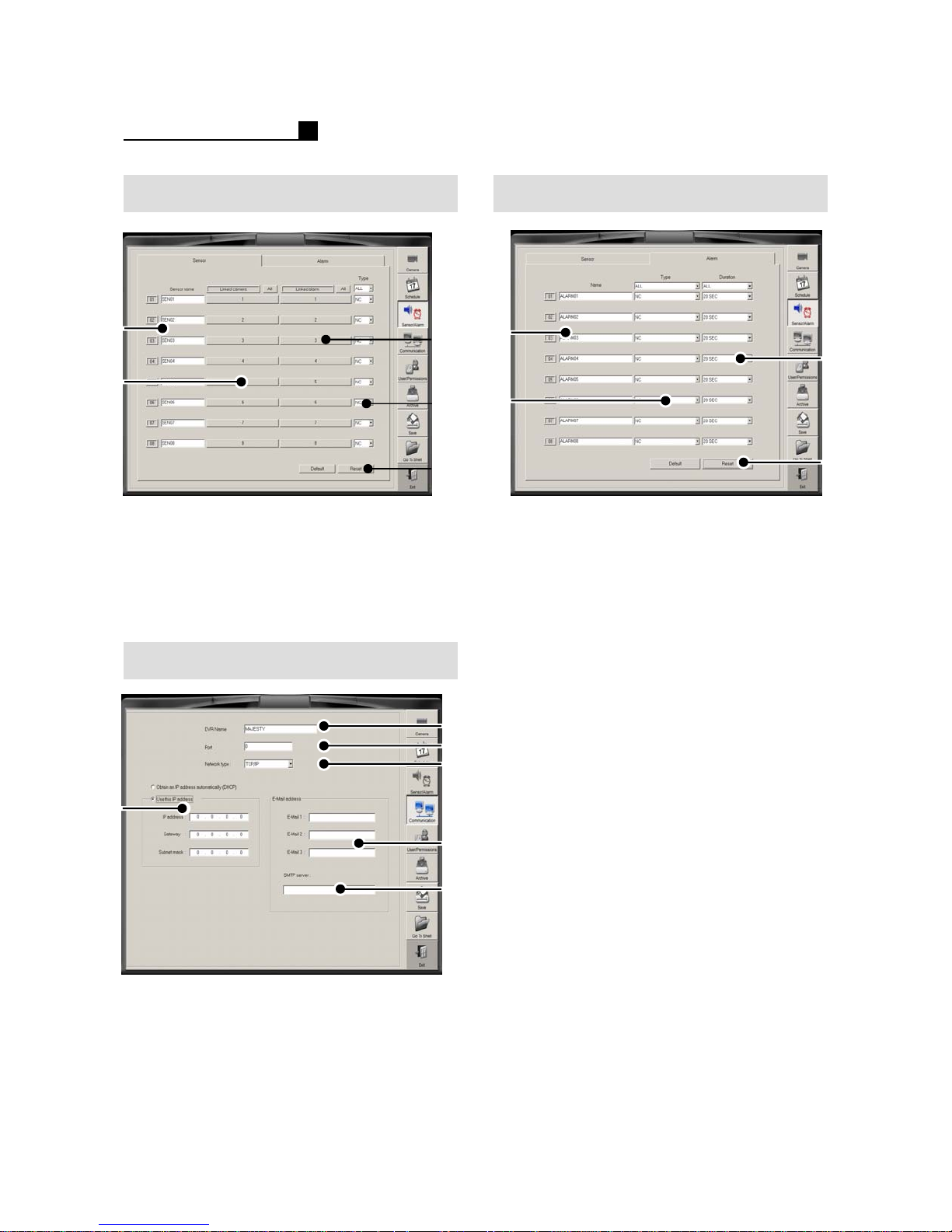
Sensor Alarm
①
②
① Sensor Name
② Linked Camera Selection
③ Linked Alarm Selection
④ Sensor Type (N/C, N/O)
⑤Default
⑥Reset
Network
③
④
⑤
①
③
②
④
① Alarm Name
②Alarm Type (N/C, N/O)
③ Alarm Duration
(1 time, 1Sec~10Min, Continue)
④Default
⑤Reset
①
②
③
④
①DVR Name
② Network Port
③ Network Type (TCP/IP,MODEM)
④ DHCP/IP Setting
⑤ E-mail list for emergency transmission.
⑥ SMTP Server
39
⑤
⑥
Page 40
OPERATION MANUAL
①
②
①
②
③
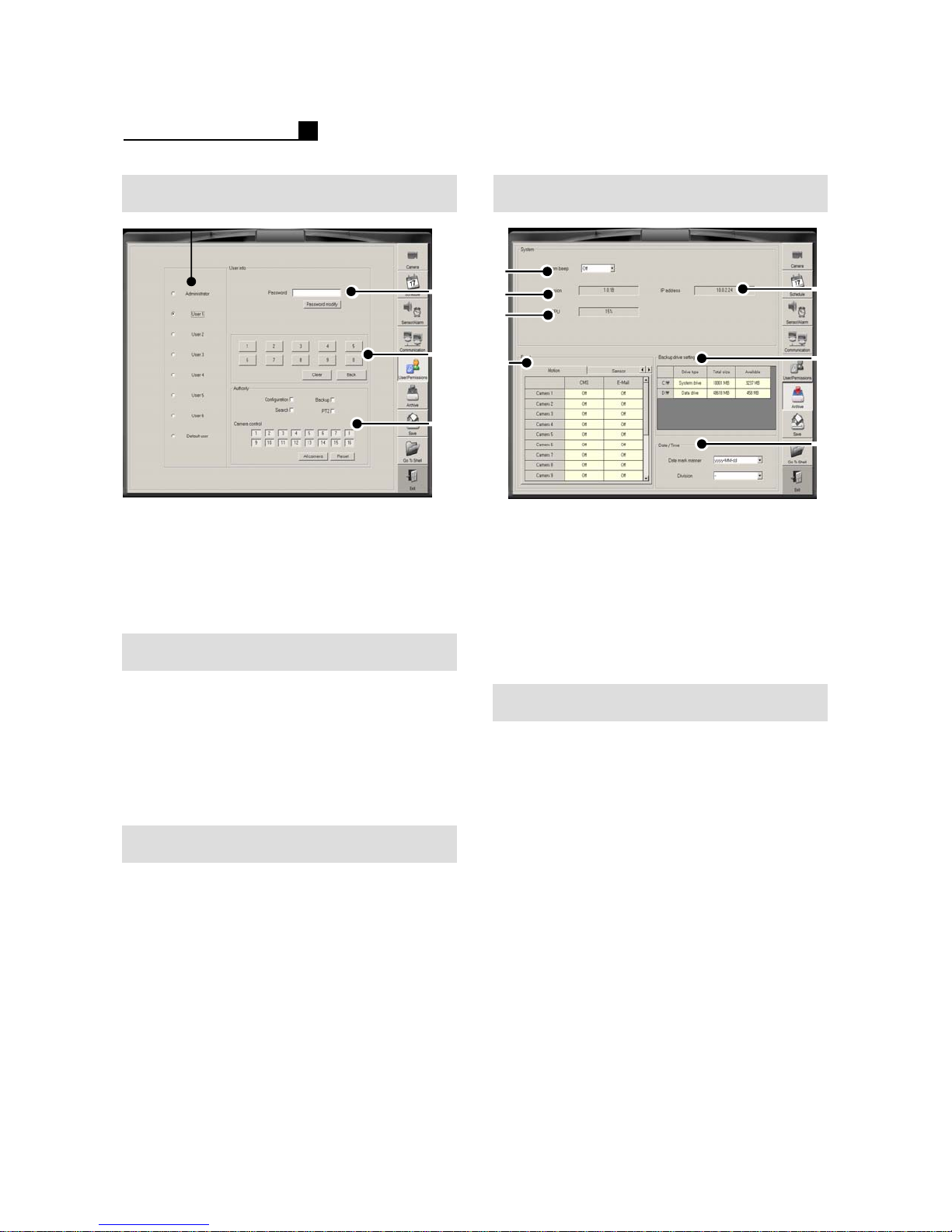
BackupUser/Password
⑤
① User Selection
② Password Configuration
③ Password No.
④ Configuration, Backup, Search, PTZ,
Camera Selection
Password Change
① Choose user
②Input P/W
③ Click “Password Modify” button
④ Input New P/W and confirm the P/W
⑤ E-mail list for emergency transmission.
⑥ SMTP Server
③
④
④
① System Beep
②S/W Version
③ CPU Usage Status
④ Event Transmission Setting
(Motion, Sensor, No Video Signal)
⑤ IP Address
⑥ Backup Drive Setting
⑦DATE/TIME Format
Backup Drive Setting
① Go to Backup Drive Setting
② Choose a drive
Ex) D:, E:, F:
③ Change the drive for Backup drive
④Save & Exit
⑥
⑦
User Authority Change
① Choose user
② Change “Authority” like Configuration,
Backup, Search, PTZ, Camera
③Save & Exit
40
Page 41
OPERATION MANUAL
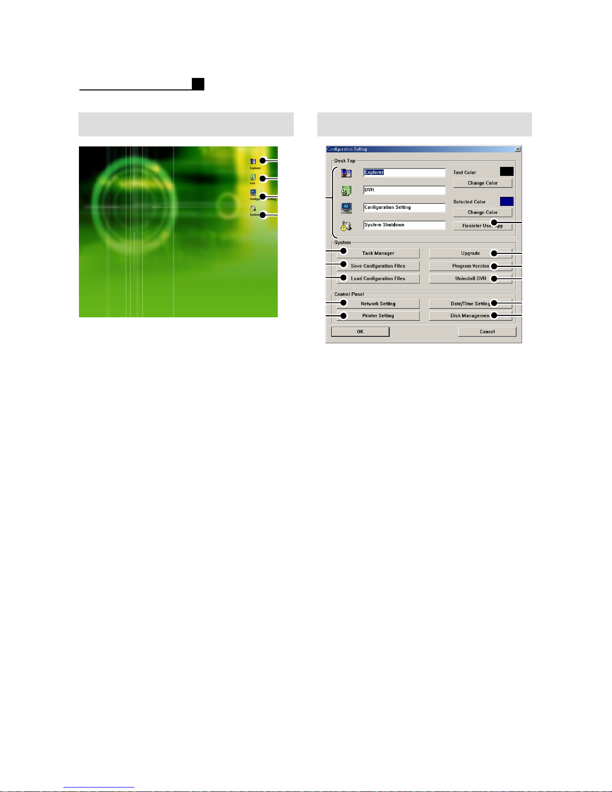
SHELLL MODE
① Windows Explorer
② Go to DVR Mode
③ Configuration Setting
(Color, Date, Network, Printer)
④DVR Shut down
①
②
③
④
Configuration Setting
①
②
③
④
⑨
⑩
①Icon Name
② Windows Task Manager
③ Save Configuration Files
④ Load Configuration Files
⑤ Register User
⑥ Upgrade DVR
⑦Program Version
⑧ Uninstall DVR Program
⑨ Network Setting
⑩ Printer Setting
⑪ DATE/TIME Setting
⑫DISK Management
⑤
⑥
⑦
⑧
⑪
⑫
41
Page 42
OPERATION MANUAL
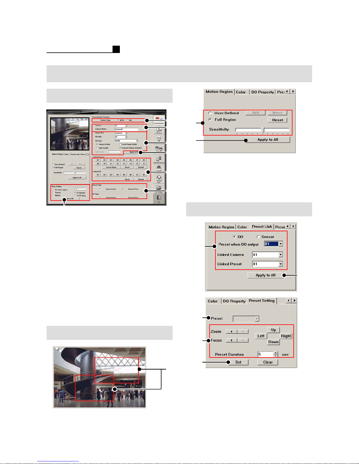
SETUP (TOPS SERIES)
Camera /Sensor
①
②
③
④
⑤
⑥
⑦
①NTSC/PAL
② Camera Name
③ PTZ Protocol & Address
Camera On/Off, Audio On/Off,
Event Pop up, Audio Gain
Resolution:
TOPS 8916 : 320 x 240, 640 x 480
TOPS 5916/5216/6916
NTSC: 352 x 240, 720 x 240, 704 x 480
PAL: 352 x 280, 720 x 280, 704 x 560
④ Apply to all cameras
⑤ Linked Alarm & DO (Alarm Out)
⑥ Sensor & DO Type
⑦ Beep Setting
②
③
PTZ
① User setting area
② User Defined – Small area
Full Region –Full area
Sensitivity
③ Apply to all cameras
①
②
③
Motion Area
42
④
⑤
①
① D/O(ALARM OUT), Sensor
② Apply to all cameras
③Preset No.
④Preset Setting
⑤ Save the Setting
Page 43
OPERATION MANUAL
SETUP (TOPS SERIES)
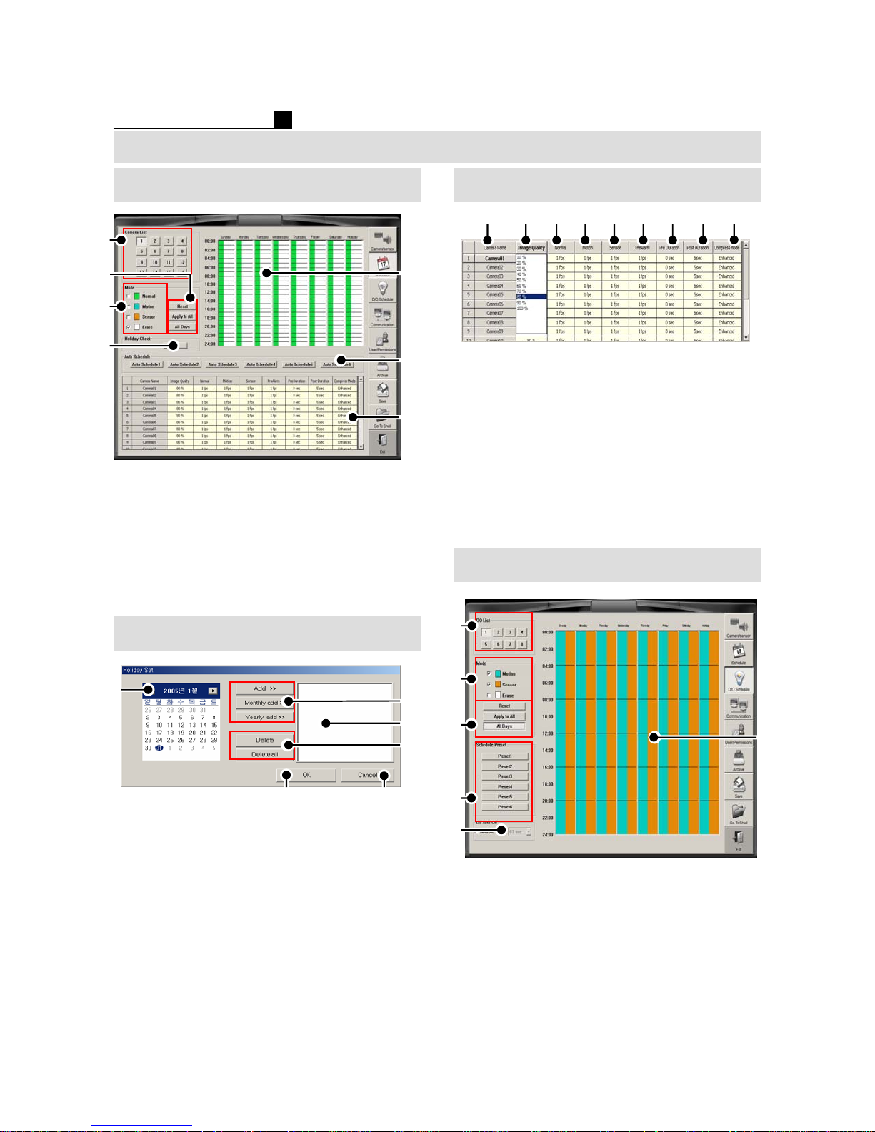
Schedule (Record) Schedule Group Setting
①
②
③
④
① Camera List
② Reset, Apply to All, All Days
③ Recording Mode
④ Holiday Setting
⑤ Schedule Setting
⑥ Auto Schedule
⑦ Image Quality, Speed, Compression
Holiday
⑤
⑥
⑦
① ② ③ ④ ⑤ ⑥ ⑦ ⑧
① Camera Name
②Image Quality
③ Normal Record Speed
④ Motion Record Speed
⑤ Sensor Record Speed
⑥ Pre-Alarm
(Recording frame for Pre-Duration)
⑦Pre-Duration
⑧ Post-Duration
⑨ Compression Mode
Alarm Schedule
①
⑨
①
⑤
① Previous/Next Month
② Add, Monthly Add, Yearly Add
③ Added Holiday List Box
④ Delete(1 time), Delete all holidays
⑤Save & Exit
⑥Exit
43
⑥
②
③
④
②
③
④
⑤
① D/O List (Alarm Out)
② Recording Mode
③ Reset, Apply to All, All Days
④ Auto Schedule
⑤ Auto D/O OFF
⑥ D/O Schedule Area
⑥
Page 44
OPERATION MANUAL
SETUP (TOPS SERIES)
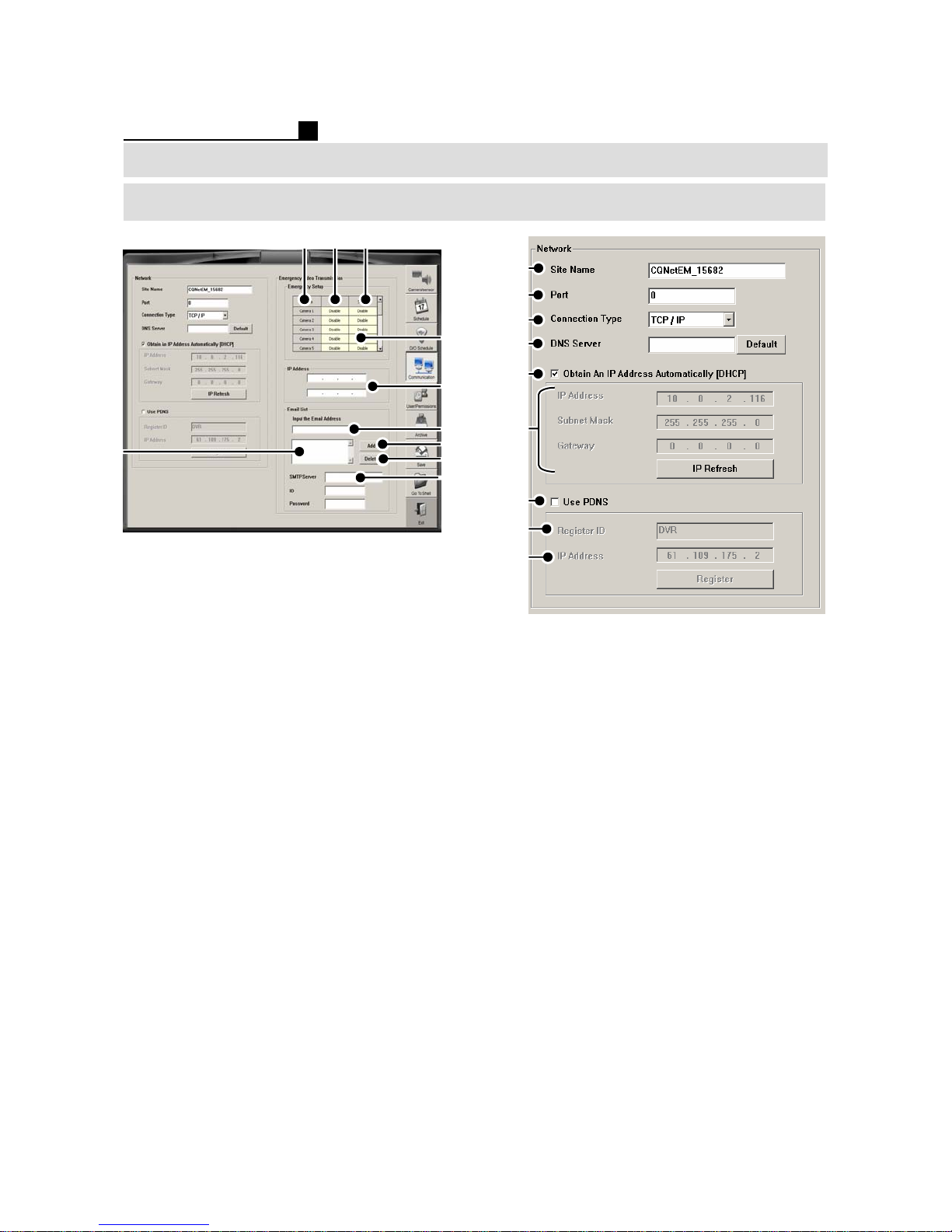
Network
①②③
④
①
②
③
④
⑧
① Camera No.
② Motion for Network Transmission
③ Sensor for Network Transmission
④ Set Transmission (Enable/Disable)
⑤ IP Address -Type IP address of PC to
have transmission
⑥ E-mail Address –Type E-mail address
to have transmission
⑦ Add E-mail Address
⑧ E-mail List Window
⑨ Delete the list
⑩ SMTP Server
Note:
Emergency program must be installed at
the PC to receive the transmission
⑤
⑥
⑦
⑨
⑩
⑤
⑥
⑦
⑧
⑨
①Site Name
② Port No. (0 is default)
③ Network Connection Type
④DNS Server
⑤ DHCP ON/OFF
⑥ IP Setting
⑦ PDNS ON/OFF
⑧ Type the DVR ID for PDNS recognition
⑨ PDNS Server IP Address
Note:
We recommend to use the default IP
address 61.109.175.2 that TOPS
provides.
44
Page 45
OPERATION MANUAL
SETUP (TOPS SERIES)
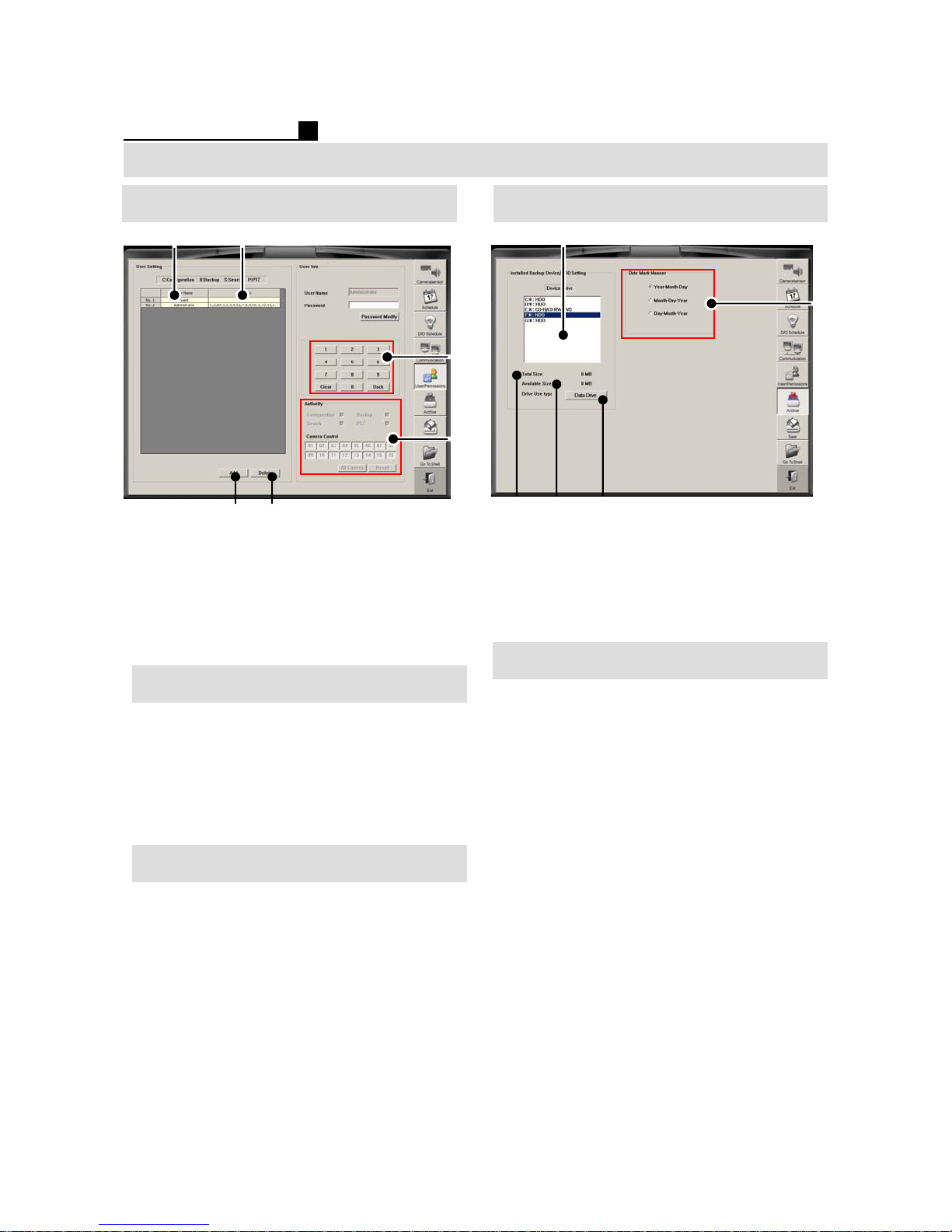
User/Password Backup
①②
⑤
⑥
① Registered User Name
②Available Functions
③ PASSWROD Input Window
④ Choose Functions for each User
⑤Add User
⑥ Delete user
Password Change
① Choose user
②Input P/W
③ Click “Password Modify” button
④ Input New P/W and confirm the P/W
⑤ E-mail LIST for emergency transmission
⑥ SMTP SERVER
③
④
①
③
②
① Show HDD,CD/DVD on DVR
② Total Capacity
③ Free Capacity
④ Set Data/Backup Drive
⑤ Date Format
④
Backup Drive Setting
① Go to Backup Device/HDD Setting
② Choose a drive
Ex) D:, E:, F:
③ Press “Data Drive”for Backup drive
④Save & Exit
⑤
User Authority Change
① Choose user
② Change “Authority”
CONFIGURATION, BACKUP, SEARCH,
PTZ, CAMERA
③SAVE & EXIT
45
Page 46
OPERATION MANUAL
SETUP (TOPS SERIES)
①
②
③
④
Configuration SettingSHELL MODE
①
⑤
① Windows Explorer
② Go to DVR Mode
③ Configuration Setting
(Icon Name, Color, Date, Network, Printer)
④DVR Shutdown
②
③
④
⑨
⑩
①Icon Name
② Windows Task Manager
③ Save Configuration Files
④ Load Configuration Files
⑤ Register User
⑥ Upgrade DVR
⑦Program Version
⑧ Uninstall DVR Program
⑨ Network Setting
⑩ Printer Setting
⑪ DATE/TIME Setting
⑫Disk Management
⑥
⑦
⑧
⑪
⑫
46
Page 47

OPERATION MANUAL
5. SUPPLEMENT
5.1 Sensor/ D/O
Installation
5.2 PAN/TILT Installation
47
Page 48
OPERATION MANUAL
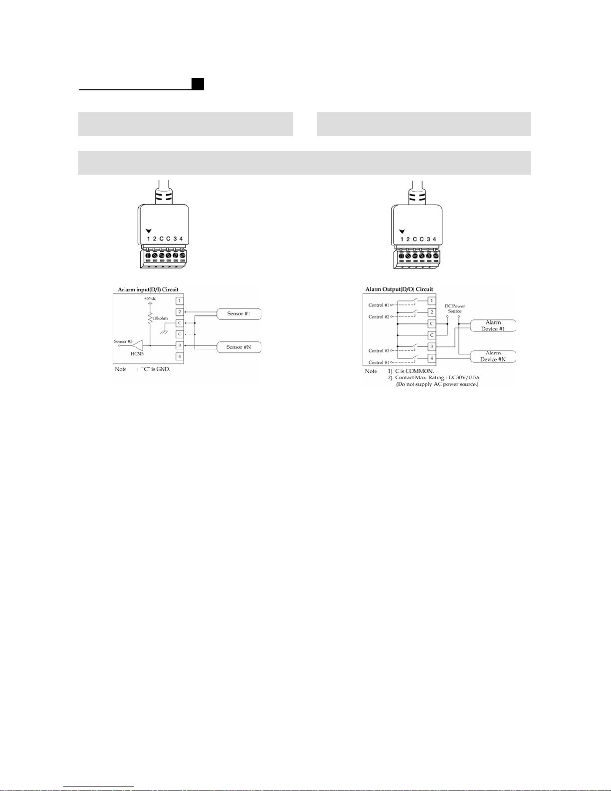
6.1 Sensor Installation 6.1 D/O Installation (Alarm)
MP5909/6916/8916
48
Page 49
OPERATION MANUAL
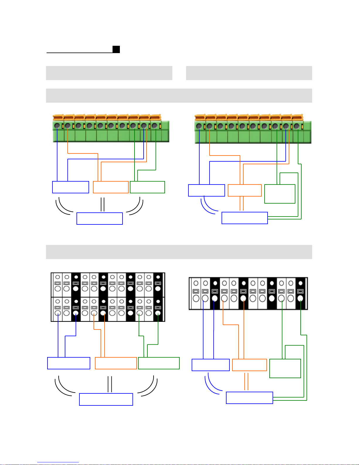
6.1 Sensor Installation 6.1 D/O Installation (Alarm)
TOPS 5909/6916/8916
12 3 4 5 6 78 GND
sensor-1 sensor-2 sensor-3
power supply
TOPS 5216
1 2 GND 3 4 GND 5 6 GND 7 8 GND
123456 78 COM
(-)
alarm siren warning
light
(-)
(+)
1 2 COM 3 4 COM 5 6 COM 7 8 COM
(+) (-)
power supply
(+)
GND
9 10 11 12 13 14 15 16
sensor-1 sensor-2 sensor-3
49
GND GND GND
power supply
alarm siren warning
light
(-)
(+)
(+) (-)
(+)
power supply
Page 50
OPERATION MANUAL
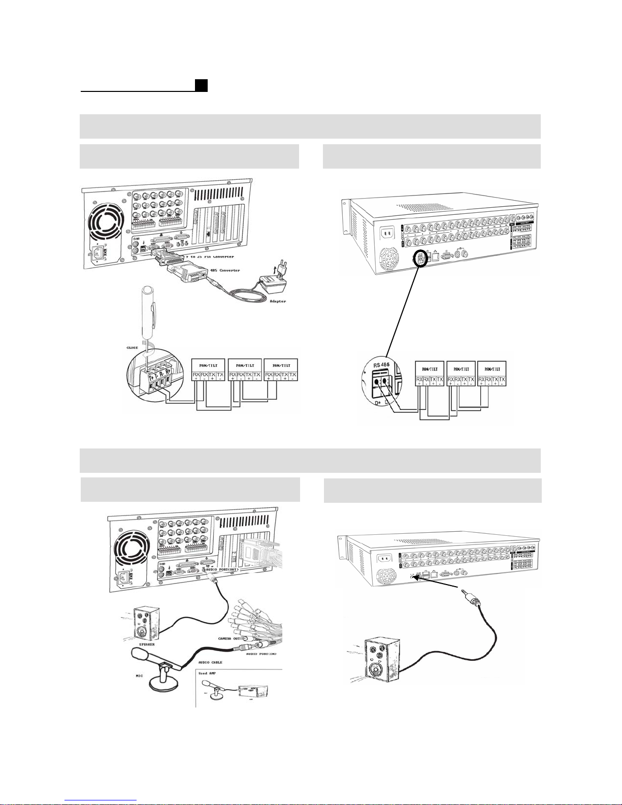
6.2 PAN/TILT Installation
TOPS 5909/6916/8916
TOPS 5216
Audio Installation
TOPS 5909/6916/8916
50
TOPS 5216
Page 51

OPERATION MANUAL
7. CLINET
CONNECTION
7.1 IP Connection
7.2 PDNS Connection
51
Page 52
OPERATION MANUAL
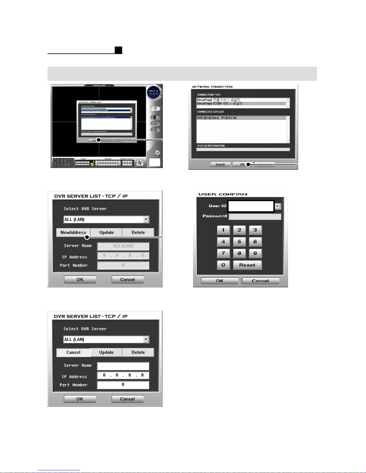
7.1 IP Connection
①
①
① Press “Find” or “Search” button
② Press “New Address” button
④ Press “OK” button
Administrator
②
⑤ Choose a “USER ID”
⑥ Select the P/W for the User ID
Default P/W is “0”.
⑦ Press “OK” button
③ Type Server name, IP address
52
Page 53
OPERATION MANUAL
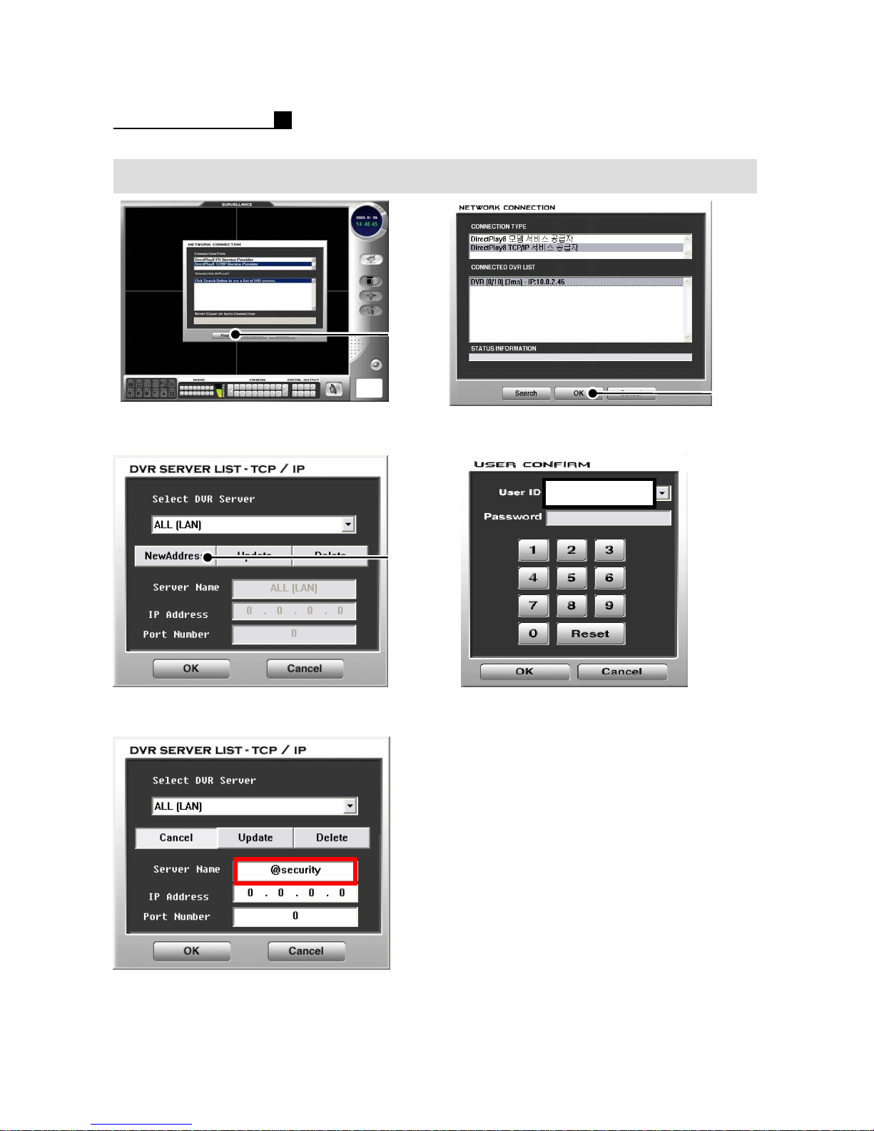
7.2 PDNS Connection
①
①
① Press “Find” or “Search” button
② Press “New Address” button
④ Press “OK” button
Administrator
②
⑤ Choose a “USER ID”
⑥ Select the P/W for the User ID
Default P/W is “0”.
⑦ Press “OK” button
③ Type Server name like the above
Ex) @security
53
Note:
PDNS Setting on DVR should be done to
Use PDNS on Client Connection.
Refer to the Page32 for PDNS Setting
on DVR
Note:
Type “@”with DVR ID into Sever Name.
Page 54

OPERATION MANUAL
8. CLIENT
SURVEILLANCE
8.1 Surveillance
54
Page 55
OPERATION MANUAL
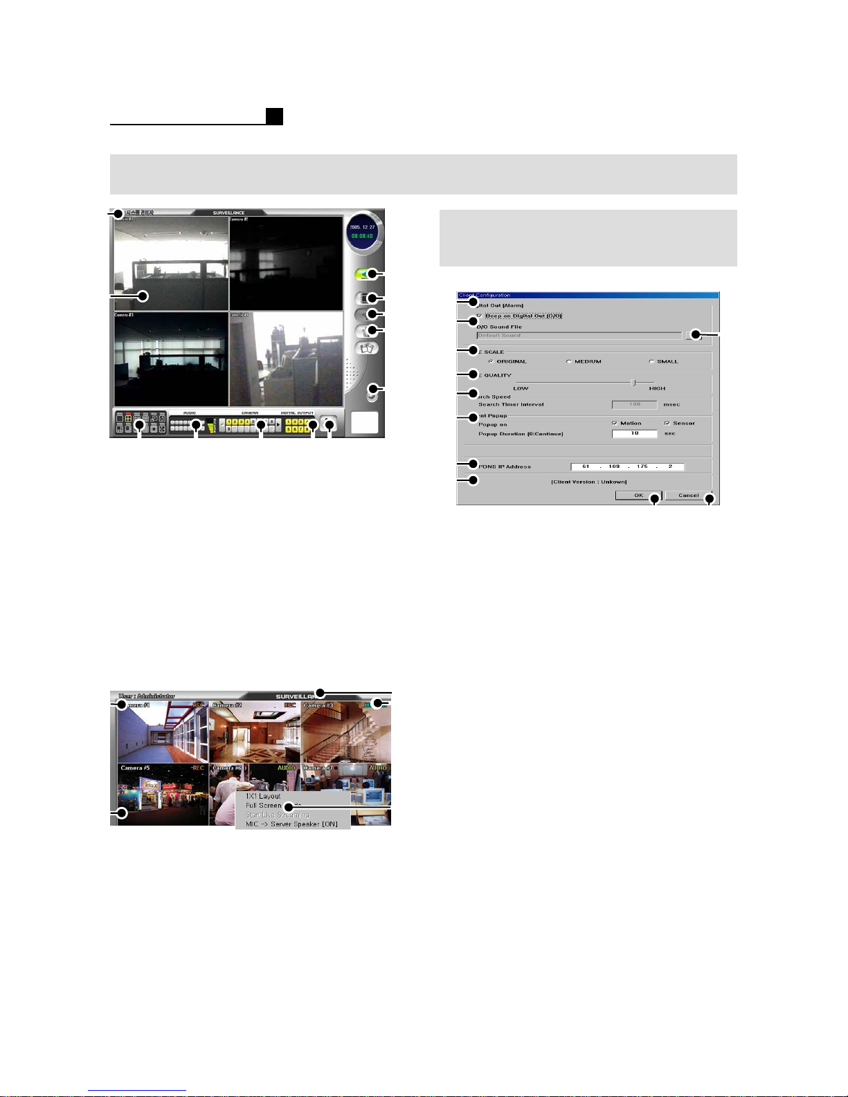
8.1 SURVEILLANCE
①
②
⑧
⑨
⑩
⑪
SPEED SETUP
(CLIENT CONFIGURATION)
①
②
③
④
③④ ⑤⑥
① User level
② Network Live View
③ Screen Division
④ Audio Selection
⑤ Camera Selection
⑥ D/O (Alarm Out) Control
⑦ Network Speed Control
⑧ Connect / Disconnect
⑨ Search Mode (Client Configuration)
⑩Pan/Tilt
⑪ Setup Mode
⑫Exit
①
Audio
②
⑦
⑫
③
④
⑤
⑤
⑥
⑦
⑧
⑨
⑩⑪
① Beep On/Off when Alarm
② Show the directory of sound file
③ Select the sound file
④ Select image size for transmission
⑤ Adjust image quality for transmission
⑥ Search Time interval to receive next
image from DVR
⑦ Event Pop up Selection
⑧PDNS IP Address
⑨Save & Exit
⑩Cancel
Note:
Live Scale: Original, Medium, Small
Original: Recorded Resolution on DVR
Medium: 320*240
Small:160*120
① Camera Name
②Audio Record
③ Show current mode
④ Show recording status
⑤Pop up Menu
- Choose one CH and right mouse click
55
Live Quality: Image Quality
If you want faster transmission from DVR
to Client. We recommend you to
set live scale “Small” and Image
quality “Low”.
It will be faster than before but the image
quality is not good.
Note:
Live Scale is not available on ME DVR.
Page 56

OPERATION MANUAL
9. CLIENT
SEARCH
9.1 Search
9.2 Detail Search
56
Page 57
OPERATION MANUAL
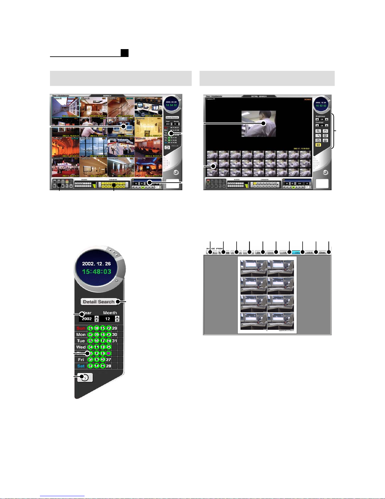
9.1 SEARCH 9.2 DETAIL SEARCH
①
②③
① Playback Image
② Screen Division
③ Camera Selection
④Calendar
⑤ Playback Control
④
④
⑤
①
③
②
① Playback Image
②Show continuous image
③Detail Search Menu
Zoom, Pan, AVI, JPG, BMP, Print
① ② ③ ④ ⑤ ⑥ ⑦ ⑧ ⑨ ⑩
①
②
③
① Select Year / Month
② Show date with recorded data in circle
③ Daylight Search
④ JPG.BMP, AVI Save, Print. Color
Note:
JPG.BMP, AVI save is not available on
some models.
57
①Print
② Print Setup
③Show previous image
④Show next image
⑤Zoom In
⑥Zoom Out
⑦ Preview 1X2 layout
⑧ Preview 2X4 layout
⑨ Preview 4X8 layout
⑩Close
Page 58

OPERATION MANUAL
10. CLIENT
PAN/TILT
10.1 PAN/TILT
10.2 Preset
58
Page 59
OPERATION MANUAL
PAN/TILT Preset
①
②
③
④
⑤
⑥
⑦
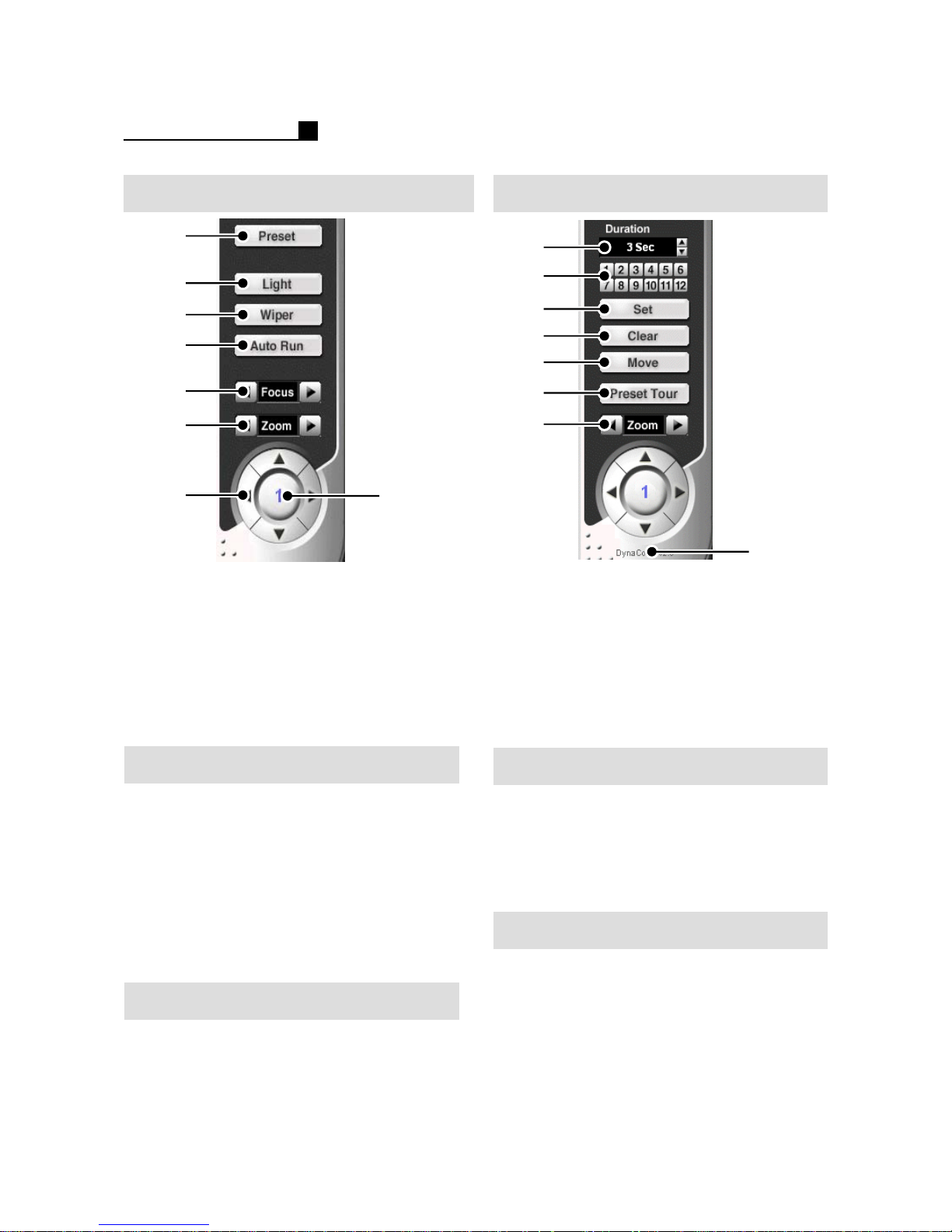
① Go to Preset setting
② Light On/Off or Camera Menu
③ Wiper On/Off
④Auto Run
⑤Focus
⑥Zoom In/Out
⑦Pan/Tilt Direction
⑧Show a selected camera
①
②
③
④
⑤
⑥
⑦
⑧
⑧
① Preset Duration
②Preset No.
③Preset Set
④Preset Clear
⑤Preset Move
⑥Preset Tour
⑦Zoom In/Out
⑧ Show Pan/Tilt Protocol
Preset Setup
① Select a camera on Live mode
② Press “Preset” button
③ Press “Set” button ON
④ Set direction and zoom for preset
⑤ Select a No. from 1~12.
⑥ Press “Set” button OFF
Note:
Camera should support “Preset” function
for Preset Setup.
PRESET TOUR
① Select a camera on Live mode
② Press “Preset” button
③ Press “Preset Tour” button ON
Move a camera according to the saved
Preset No. from 1~12
59
Clear Preset Setup
① Select a camera on Live mode
② Press “Preset” button
③ Press “Clear” button ON
④ Select a No. from 1~12
⑤ Press “Clear” button OFF
PRESET MOVE
① Select a camera on Live mode
② Press “Preset” button
③ Press “Move” button ON
④ Select a No. from 1~12
 Loading...