

Page 1
TopRCModel-USA.com
Page 2
第 2 页,共 17 页
Page 3
第 3 页,共 17 页
Page 4
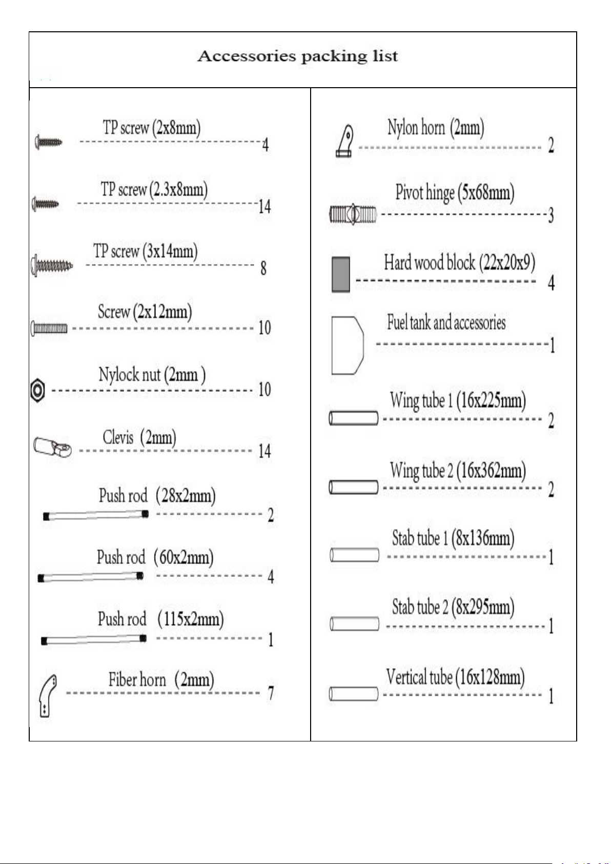
Accessory part lists for wing installation.
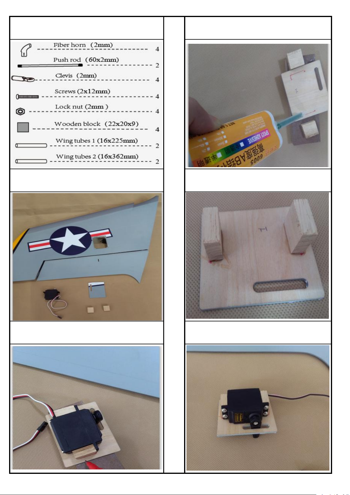
3. Epoxy the wood block to the servo tray base on the
mark line.
1. Ready for assemble the wing servos.
4. Epoxy the wood block to the servo tray tightly.
2. Put the wood block to appropriate position base on the
servo tray, mark out with red.
5. Assemble the servo to the servo tray with screws.
第 4 页,共 17 页
Page 5
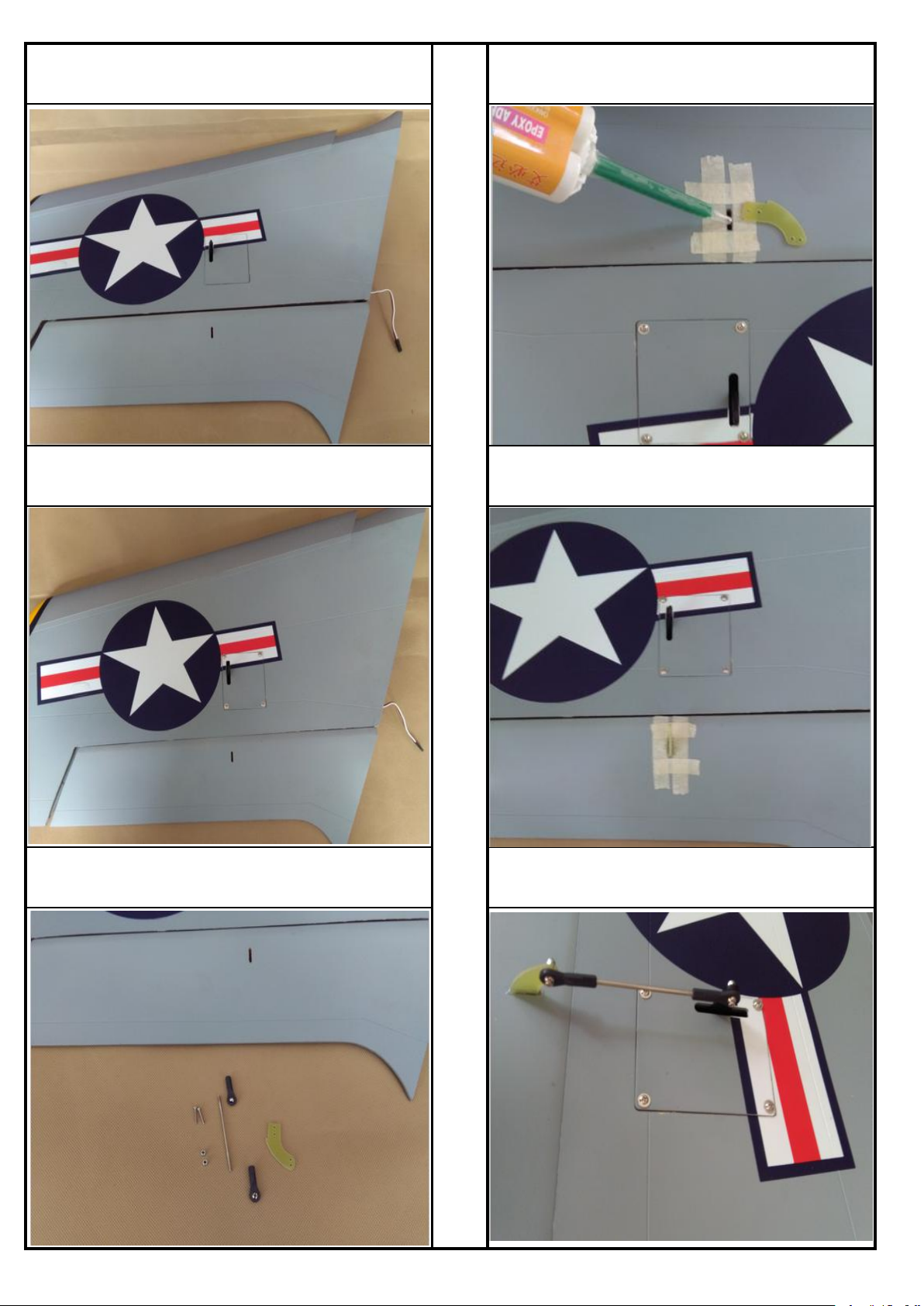
6. Assemble the servo to the wing
9. Before glue the arm to the slot, put masking tape
around the slot to keep clean.
7. Drag the servo line out of the wing.
10. Glue the arm to the slot and wait it dry.
8. Prepare to assemble the push rod arm.
11.Connect the arm of the flap and servo arm with push
rod.
第 5 页,共 17 页
Page 6
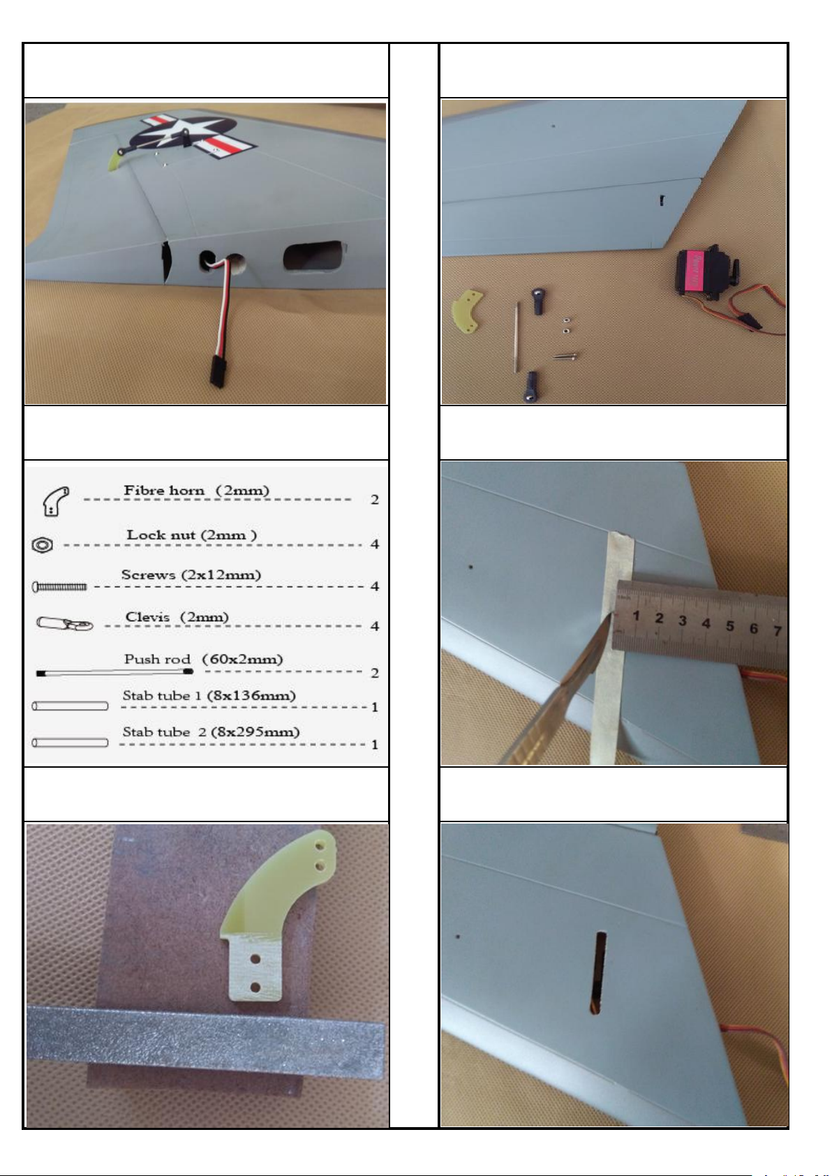
12.The scketch map of the servo for the wing assembly
finished.
14.Prepare the parts for assembly the stab servo.
Accessories part list for the stabilizer installation.
15.Measure the deepth and mark out where the servo
would location.
13.Sanding the fiber horn.
16.Trim a lot for the stab servo arm.
第 6 页,共 17 页
Page 7
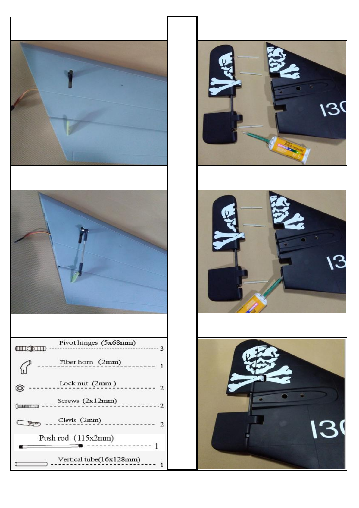
17.Glue the horn to the elevator and assemble the servo to
the stabilizer.
19.Apply instand type AB glue to the slots in the rudder.
18.Connect the arm of servo to the horn with push rod.
20.Apply instand type AB glue to the slots in vertical fin.
Accessories part lists for the rudder installation.
21.Assemble the rudder to the vertical fin and make sure
it can move freely.
第 7 页,共 17 页
Page 8
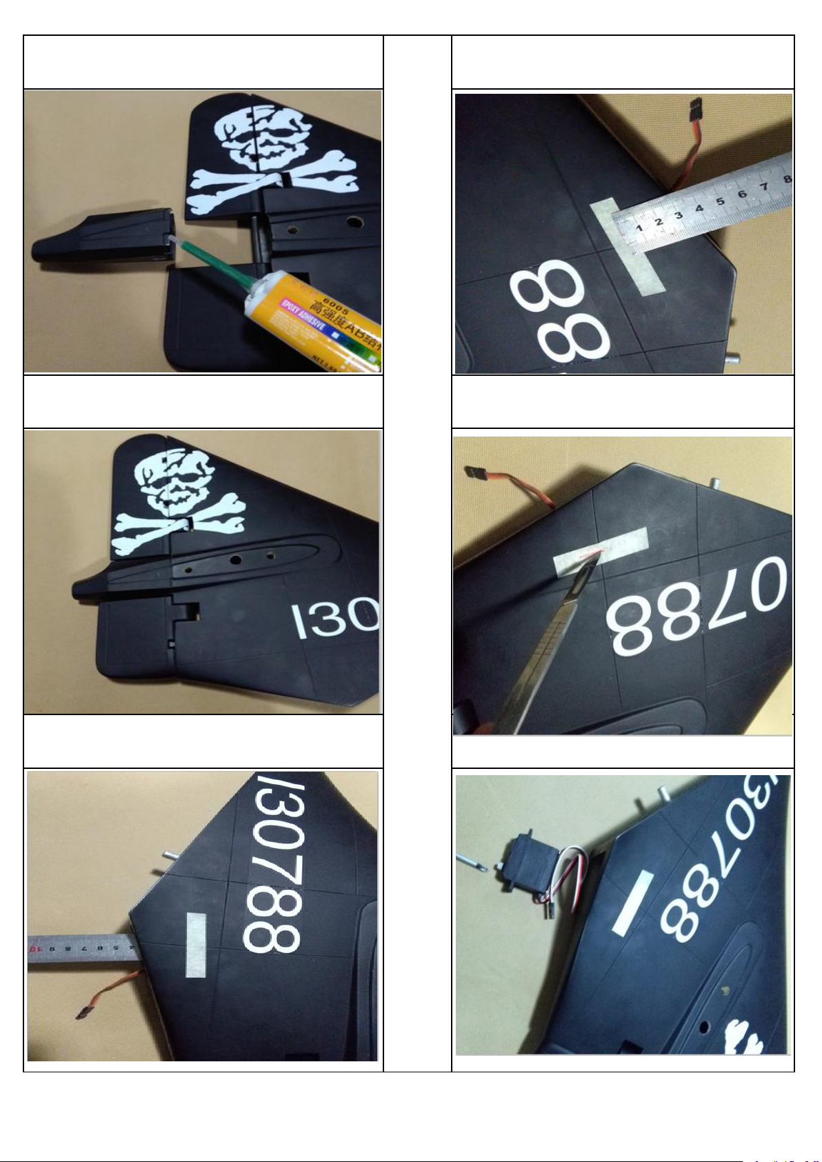
22.Apply instand type AB glue to the slots in the tail cone. 25.Mark it out at the outer side of the vertical.
23.Assemble the tail cone to the vertical fine tightly.
26.Trim a slot for the servo arm.
24.Measure the deepth of the rudder servo position.
27.Assemble the servo into the vertical fin with screw
driver.
第 8 页,共 17 页
Page 9
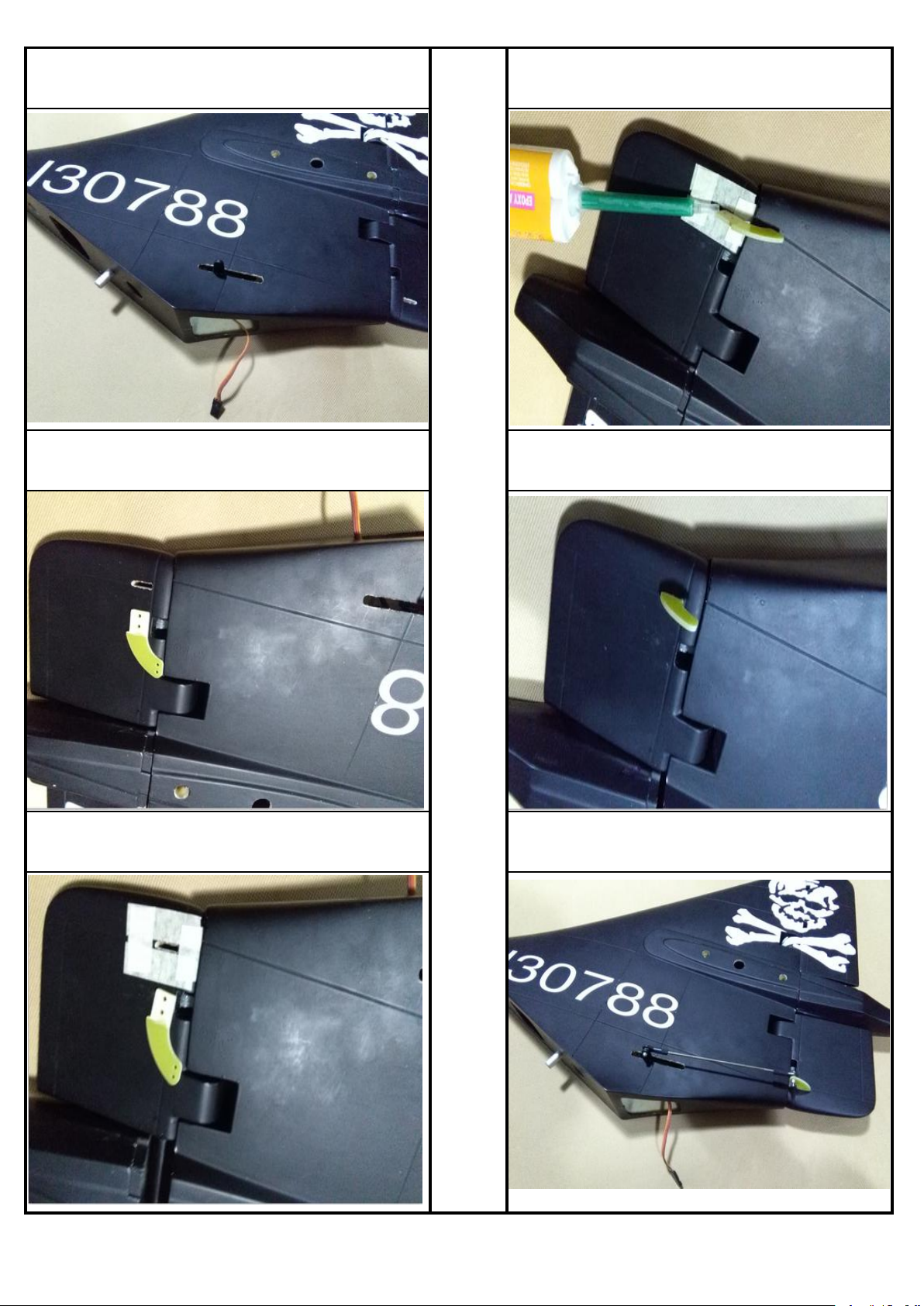
28.The sketch map after the servo of rudder assembly. 31.Glue the fiber horn to the slot tightly.
29. Trim a slot at the appropriate position in the rudder.
32.Remove the masking tape after the glue dried.
30.Put masking tape around the slot to keep the plane body
clean after work done.
33.Connect the servo arm to the rudder fiber horn .
第 9 页,共 17 页
Page 10
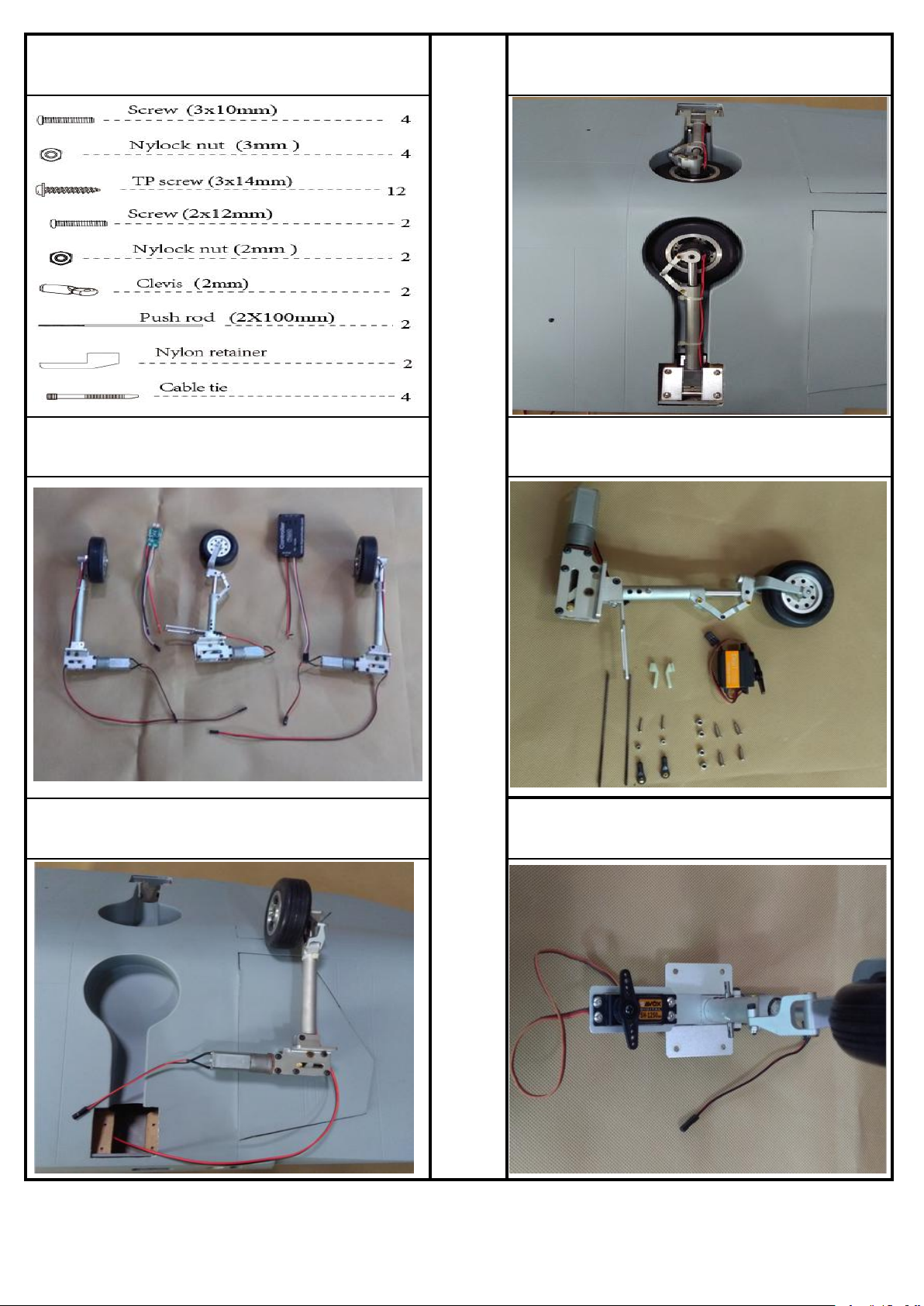
Accessory part lists for retract installation(Optional and
need purchased separately).
36.The sketch map after the main retracts assembled
completely.
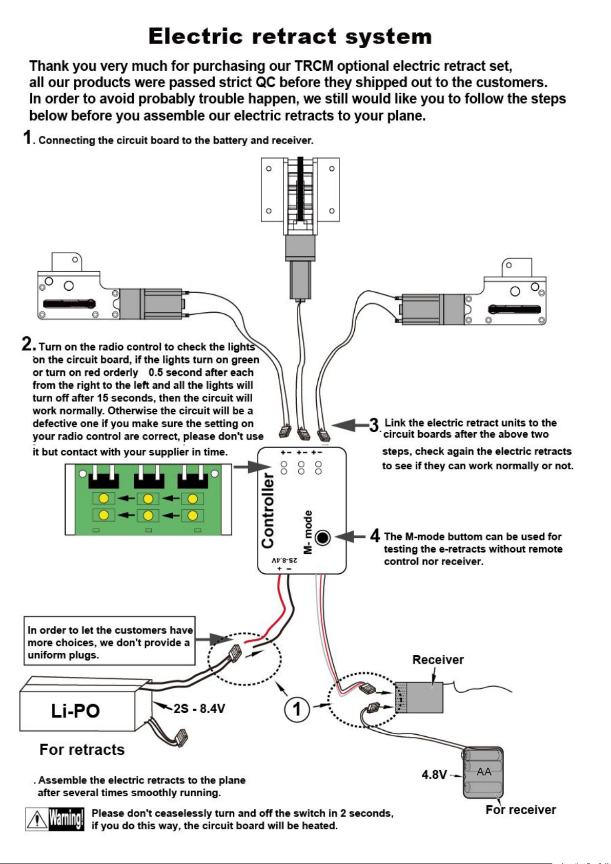
34.The sketch map of the electric retract system (Optional
and need purchased separately)
37.The sketch map of the nose gear and nose gear servo
parts.
35.Assemble the retract to the fuselage with screws.
38.Assemble the nose servo to the nose gear.
第 10 页,共 17 页
Page 11
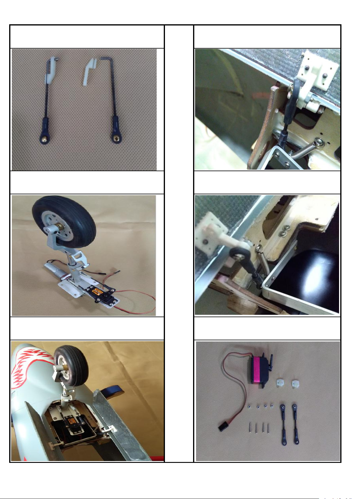
39. Bending the push rod to a propriate angle and assemble
them to the retainers .
42.Connect the clevis to the hatch hinge with screws and
nuts.
40.Assemble the nose gear completely.
43.Connect the clevis to the hatch hinge with screws and
nuts.
41.Assemble the nose gear to the fuselage with screws.
44.The servo parts for the air brake.
TopRCModel-USA.com
Page 12
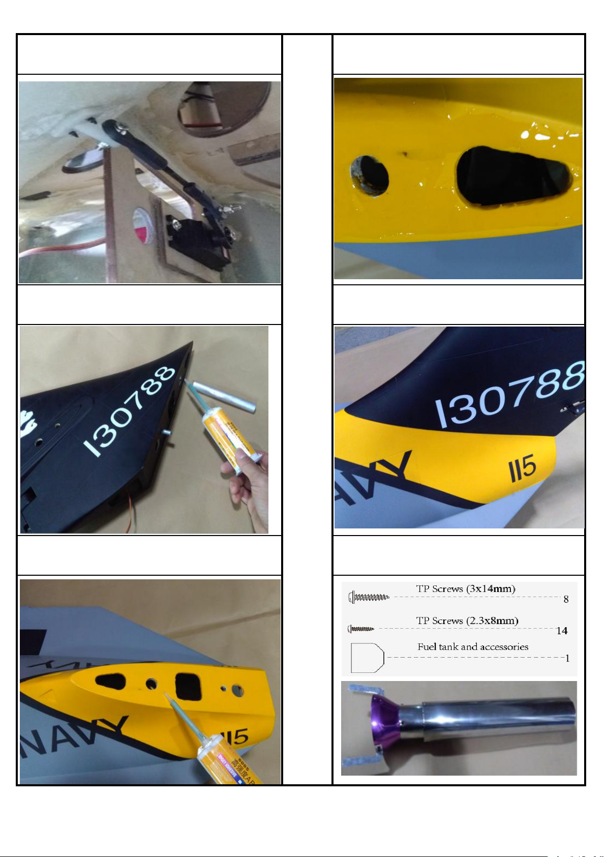
45.Assemble the nylon horn to the air brake inner side,
assemble the air brake servo to appropriate position in the
fuselage, connect the horn to the servo arm with push rod.
48.Put the fin bolt into the vertical fin.
46.Glue the tube to the vertical fin tightly.
49.Glue the vertical tail parts to the main fuselage tightly.
47.Offer the glue to the surface of the vertical tail section.
Accessory part lists for fuel tank installation.
第 12 页,共 17 页
Page 13
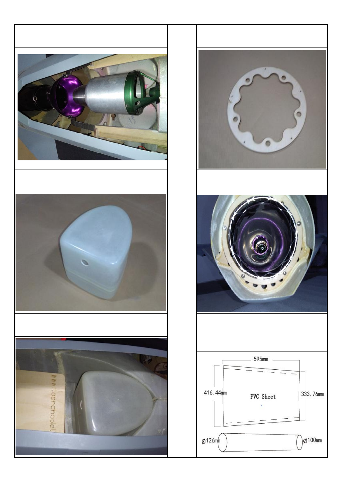
50.Assemble the turbine and tail pipe to the fuselage. 53.Prepare the tail pipe mount.
51.Fuel tank ready.
54.Fix the tail pipe to the tail pipe mount.
52.Fix the fuel tank to the fuselage.
EDF installation steps for reference (All the devices
and accessories need purchased by customer
himself) First prepare a 0.6mm PVC Sheet, cut the
sizes as the picture below and glue them up.
TopRCModel-USA.com
Page 14
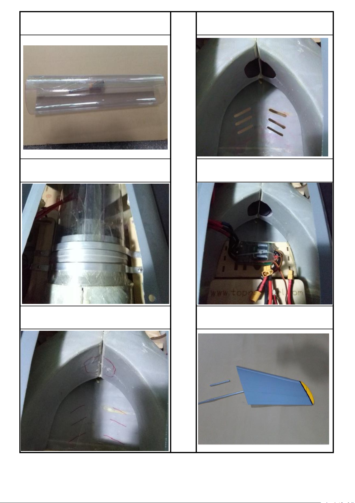
55.The sketch map when the PVC sheet glue up. 58.The sketch map when after the position hollowed
56. Seal the PVC tube to the EDF and assemble them to
the air intake.
59.The sketch map after the ESC and battery
installation.
57. Mark out the position in the air intake and fuselage
where there need to be hollowed.
60.Prepare the parts for assemble the stab.
TopRCModel-USA.com
Page 15
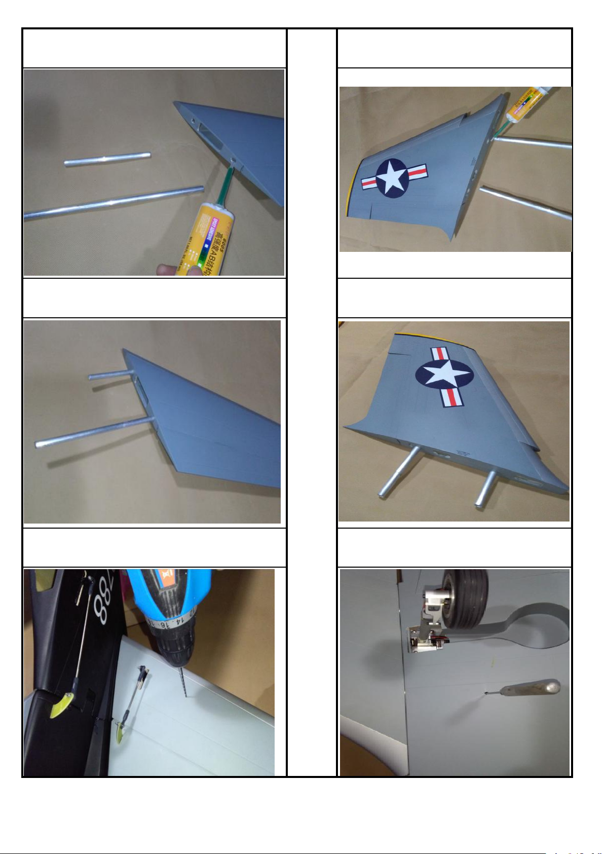
61.Add some glue to the holes of stab. 64.Add some glue to the holes of wing.
62.Fix the stab tube to the holes tightly.
65.Fix the wing tube to the holes tightly.
63.Assemble the stab to the fuselage and lock it to the
fuselage with screws.
66.Assemble the wing to the fuselage and lock it to
the fuselage with screws.
TopRCModel-USA.com
Page 16
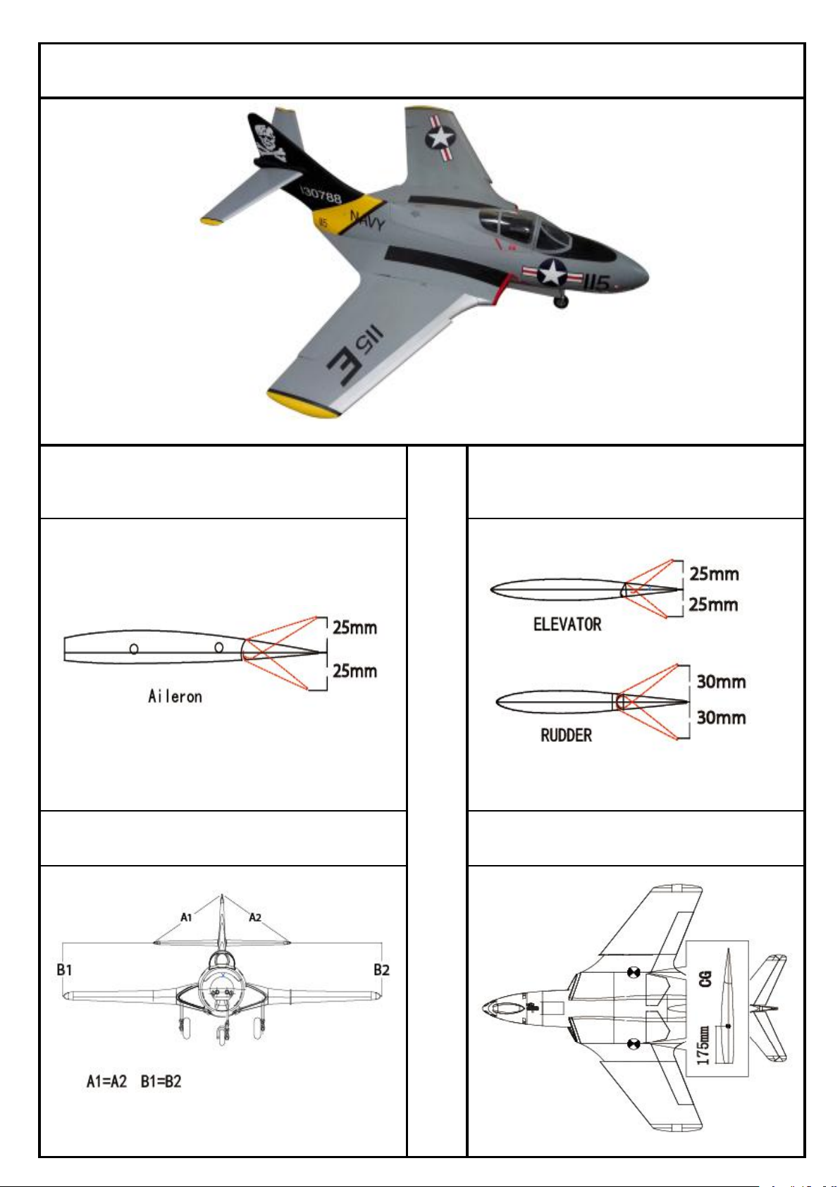
The schetch map once the model completely assembly.
67. Adjust the travel of each control surface to the values in
the diagrams. These values fit general flight
capabilities.Readjust according to your needs and flight
level.
69. Adjust the travel of each control surface to the
values in the diagrams. These values fit general flight
capabilities.Readjust according to your needs and
flight level.
68.Check all the datas well. make sure all sections glue
tightly. Otherwise if coming off during flights, you'll lose
control of your airplane which leads to accidents!
70.C.G: Never fly before checking the CG's required
position. Never fly the model without well balancing.
Page 17
TopRCModel-USA.com
 Loading...