

Page 1
AGE 14+
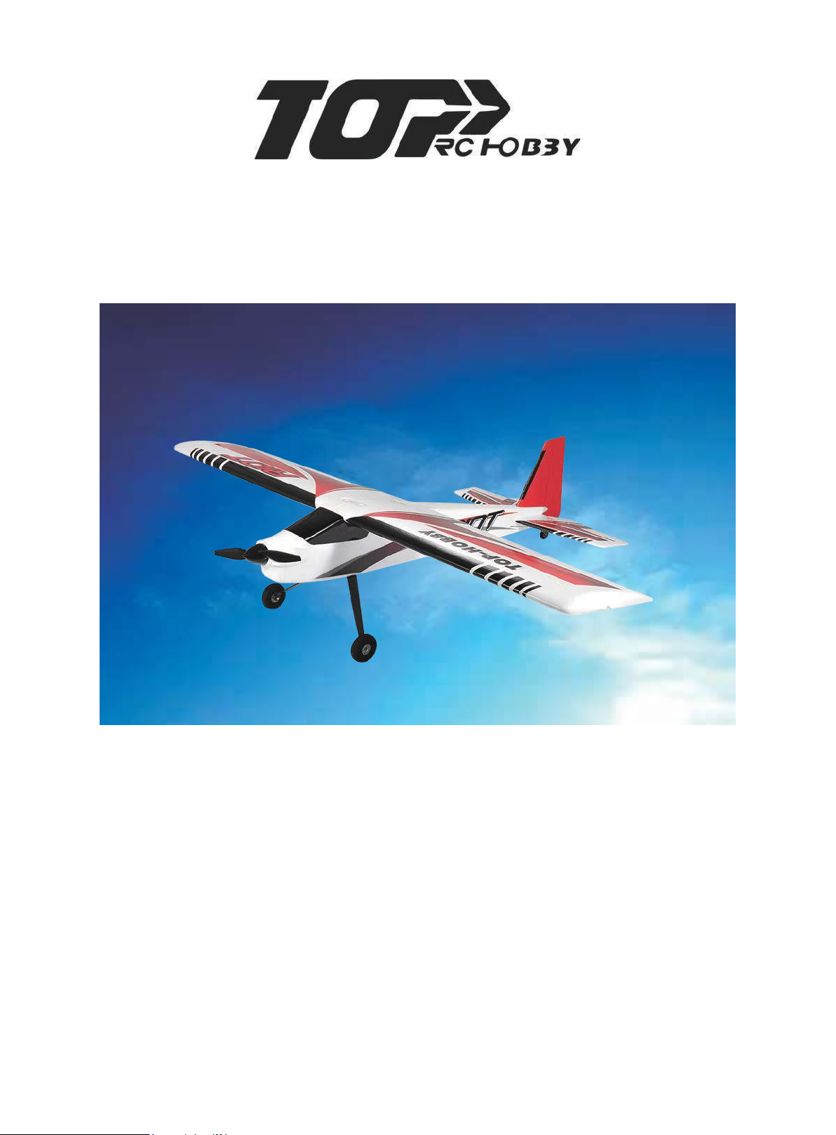
RIOT
R/C AEROBATIC SPORTS AIRCRAFT
ASSEMBLY AND INSTRUCTION MANUAL
www.toprchobby.com
Page 2

Warning
This radio controlled model is not a toy. It requires skill to fly and is not recommended for use by
beginners without assistance from an experienced model pilot. It should not be operated by
children without the supervision of a suitably experienced adult. TOP RC HOBBY reserves the
right to modify the specification of this model at any time.
Safety Precautions
1. Do not attempt to repair or modify this aircraft with non-factory parts.
2. Never fly this model over roads, railway lines, near to power lines, airports, do not fly this
model in excessively strong winds, in the rain, or thunderstorms.
3. Do not fly or launch the model towards people.
4. Keep hands and face away from rotating propeller at all times.
S. We strongly recommend that all fixings and fasteners used in the construction of this model
are checked regularly for integrity. Failure to do so could cause a crash, injury to yourself or
others around you.
6. We only recommend the use of 2.4GHz radio equipment with this model.
Disclaimer
1. This radio controlled model is not a toy. Used incorrectly it is capable of inflicting serious
injury to persons or damage to property. The owner/pilot assumes all responsibility for any
damage to persons or property resulting from the use of this product.
2. The manufacturer and distributor decline all responsibility for any liability arising from use of
this product.
3. It is very important that you follow all instructions for assembling and setting up of this model.
Failure to do so could result In a loss of control and possibly a crash.
“EPOFLEXY”
“EPOFLEXY” is a very tough and durable material perfect for the manufacture of model aircraft.
When using screwed fixings with “EPOFLEXY” components it is important to tighten the screws
sufficiently to provide a firm fixing.
Excess tightening could result in the foam material becoming compressed, possibly damaging
or distorting the part. Take care to ensure that all screws are tightened sufficiently to provide a
firm fixing, but do-not over tighten. We recommend that all fixings are checked regularly for
security and safety purposes.
Page 3

Overview
Thank-you for purchasing this radio controlled model aircraft. The RIOT offers a stunning
combination of terrific looks and sensational flight performance. Manufactured from
“EPOFLEXY” it is extremely robust, however, in the event of a “less than perfect” arrival, we
supply a range of spares to get you flying again in the shortest time. It is capable of a wide
range of amazing aerobatic manoeuvres to thrill the experienced pilot, but with reduced control
throws it provides a solid and predictable flight performance, perfect for the sports flyer.
We are certain you will enjoy your new model, please take the time to read this manual
thoroughly and understand its contents completely prior to commencing assembly.
Key Features
Powerful Brushless Motor
40A Brushless Electronic Speed Controller
Efficient 2 Blade Propeller
Pre-installed servos
“Live” Control Surface Hinging
Durable “EPOFLEXY” Construction
Steerable Tail Wheel
Superb Flight Performance
High Brightness LED Lighting System
Specification
Wingspan: 1400mm
Length: 1130mm
Weight: 1480g
Wing Loading: 40.3g/dm2
Motor: 3720-KV880 Out-Runner Brushless
ESC: 40A Brushless
Servos: 9g*2+17g*2
Battery Required: 2200 - 2400mAh 11.lv Li-Po (Not Included)
Recommended Battery: 2200mAh 11.1V 20C
Page 4
Assembly instructions
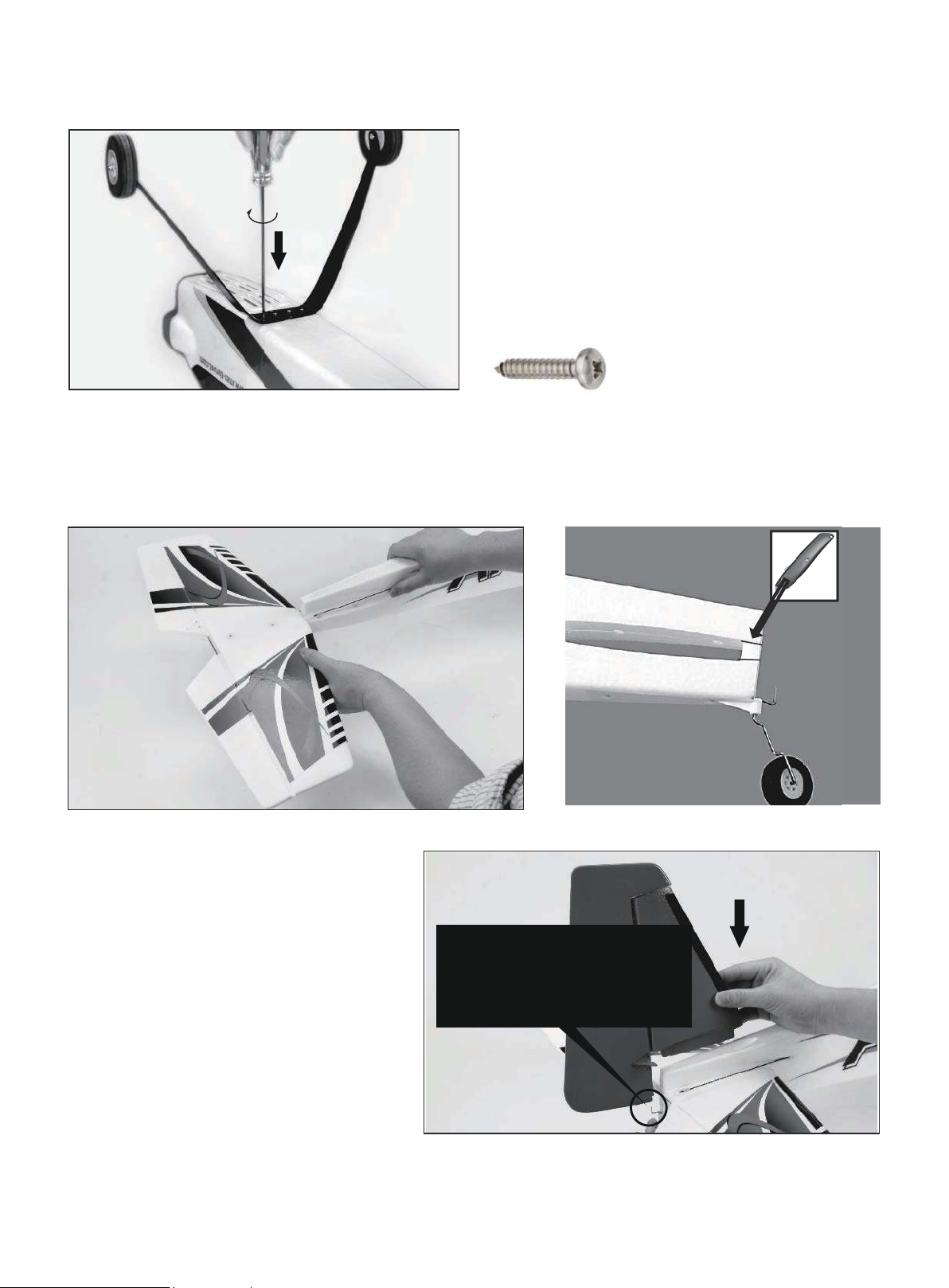
1. Undercarriage
Fix the undercarriage in position with the four 2.6 x
12mm self-tapping screws as shown, (image A). If the
screws become excessively tight whilst fixing, simply
back them off a turn or two, and then continue.
Note: The undercarriage legs are angled towards
the front of the fuselage.
4 x Screw 2.6 x 12mm
2. Horizontal Tail-Plane
Remove the moulded tab at the end of the fuselage with a sharp knife. Slide the horizontal tail- plane into the
fuselage slot as shown, (image B). Make certain that the holes in the tail-plane lineup with the corresponding
fuselage holes. If desired, a small amount of foam glue can be used for maximum security.
3. Vertical Fin & Rudder
Install the vertical fin and rudder assembly
into the slot in the fuselage. Please make
certain that the tail-wheel control wire is
located correctly in the rudder slot as shown,
(image C).
If desired, a small amount of foam glue can
be used for maximum security.
Note:Tail wheel wire needs to
be inserted the plastic hole of
the rudder.
Page 5
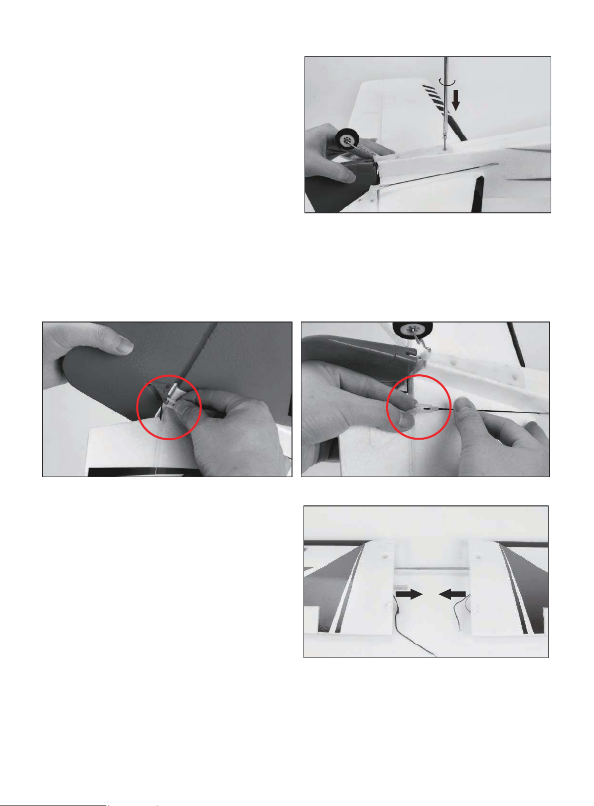
4. Tail-Plane Fixing
Fix the horizontal tail-plane and vertical fin in position
with the two 2.6 x 35mm screws provided, (imageD).
The screws must be tightened sufficiently to securely
fix the parts in position, however be careful not to
over-tighten the screws.
2xScrew2.6x35mm
5. Tail Control Horns
Connect the rudder and elevator snap-links to their respective control horns as shown in images E&F.
Minor adjustment to obtain perfect neutral positions of the control surfaces can be achieved by rotating the
plastic link on the threaded portion of the control push-rod.
Make certain the plastic link is securely “snapped” closed when connected to the control horn.
6. Wing Assembly
Locate the 500mm aluminium wing joining spar and
slide into the round aperture of one wing panel up to
the centre locating collar. Locate the small plywood
wing locking plate and insert into the rectangular
aperture behind the main wing spar, (image G). Slide
the remaining wing panel onto the exposed portion
of the aluminium spar. The plywood locking plate will
ensure perfect alignment of the two wing halves. Be
certain that all wires are routed correctly via the
moulded slots and do not foul the joint between the
wing roots. If desired, a small amount of foam glue
can be used for maximum security.
Page 6
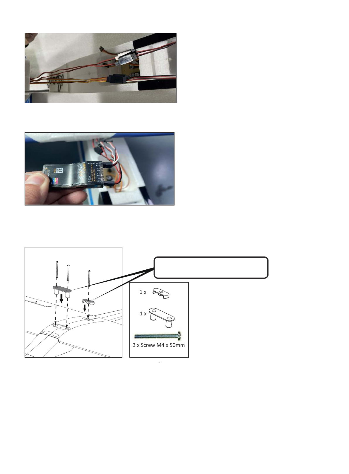
Please connect the 3-Pin wire leads for Aileron
from the wings to the 3-Pin Y lead provided,
and connect the 2-Pin LED wire leads from the
wing to the 2-Pin Y lead provided. Pay
attention to the polarity of this connection.
Please plug the 3-Pin Aileron Y lead to the
Aileron channel of your receiver. And plug the 2Pin LED Y lead to any other channel of the
Receiver except for Aileron, Elevator, Throttle,
Rudder channels. Please pay attention to the
polarity of the connection.
7. Wing Fixings
Note: The plastic connectors are
angled for the wing camber.
Insert the front and rear plastic connectors into
the wing, (image J). They are angled to pro-
vide a perfect fit. Make certain you have them
located correctly! The wing can now be
trial-fixed in position onto the fuselage using
the 3 x M4 x 50mm screws provided.
Page 7
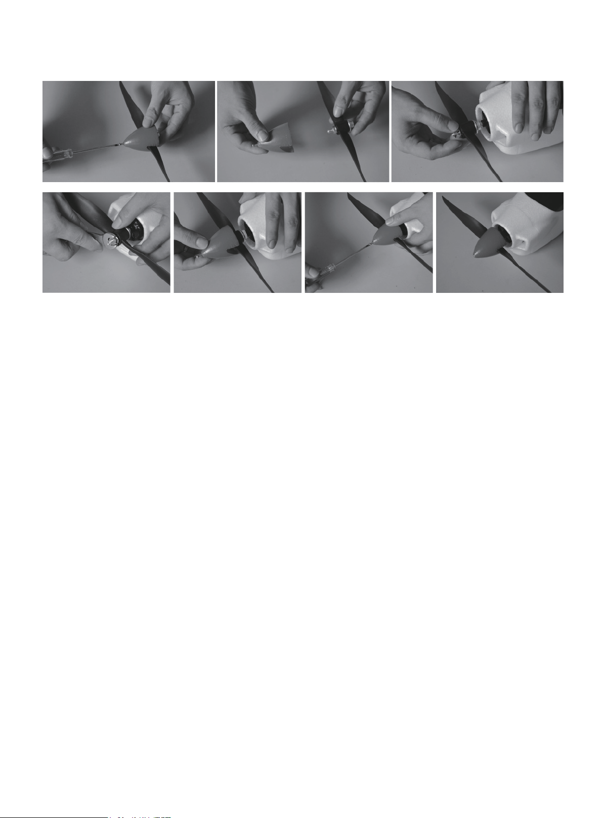
8. Propeller & Spinner
1. Please take off the propeller set from the package. Disassemble the spinner by screw driver.
2. Please install the assembled propeller to the motor shaft.
3. Lock the propeller by wrench.
4. Assemble the spinner.
5. Lock the spinner by the screw driver.
6. Assembly of propeller is finished.
Securely tightening the nut will clamp the adaptor to the motor shaft and fix the propeller in position. Note: Use
of excessive force will cause damage to the aluminium adaptor.
Attach the front section of the plastic spinner and secure with the two screws provided.
Note: It is essential that the propeller is securely fixed. Failure to do so could result in
serious injury.
9. Receiver Installation
Connect the speed controller to the throttle channel of your receiver, (not included). This wire is easily
identified, it is the only one that is routed from the front of the model.
Connect the rudder and elevator servos to the corresponding channel outputs of the receiver and connect the
plug from the aileron “Y” lead to the aileron channel output. There is a moulded recess in this compartment
which is sufficient to accommodate most popular 2.4GHz receivers; however there is ample room elsewhere to
locate yours if it does not.
We recommend that it should be securely positioned with self-adhesive “Velcro”.
You must adhere to the receiver manufacturer recommendations regarding positioning and aerial routing.
Page 8
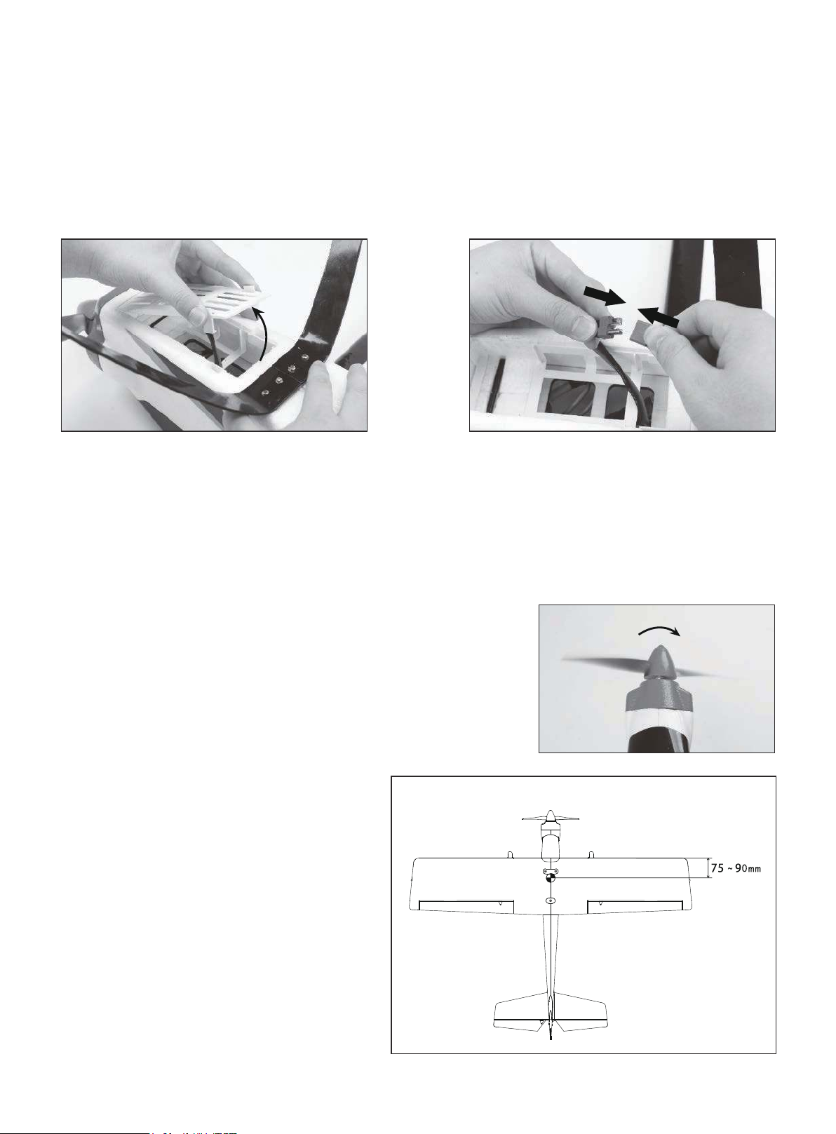
10. Battery Installation
The battery compartment is accessed by gently squeezing the two raised white tags and lifting the rear of the
front hinged cover, (image M). Your flight battery, (not-included) can easily be installed and connected to the
factory fitted “T” style connector, (image N). Make certain the battery and cover are both secure before flight,
the battery compartment has been made bigger to except larger batteries if required, if your battery is loose in
the compartment please use some foam / sponge packing to keep it in place.
11. Control Surfaces
Check that all control surfaces are centred and responding correctly to transmitter inputs. Adjustments can be
made to control surface centres by carefully rotating the plastic control horns on the threaded portion of the
metal control rods. Use the servo reversing function on your transmitter for any control that is not responding
in the correct sense to control inputs. Make certain that all plastic links are securely “snapped” closed and that
all control surface hinges are secure. Use a small amount of foam glue if any hinges are not firmly attached.
12. Propeller Rotation
Double-check that the propeller is securely fixed and it is rotating in
the correct direction, (image 0).
13. Centre of Gravity
It is vital that you check that the centre of
gravity is correct. Failure to do so could result
in a complete loss of control. We recommend
the balance point of the model, complete with
battery, should be 75 -90mm back from the
leading edge of the wing for initial flights,
(image P). Very experienced pilots may wish to
move the balance point further back after initial
flight testing.
Page 9
14. Control Surface Deflections
We make the following recommendations for control surface deflections. Experienced pilots may wish to
increase these movements after initial flight testing.
Ailerons: 10mm each way.
Elevator: 10mm each way.
Rudder: 12mm each way.
We hope you enjoy many happy and safe flights with your
new TOP RC HOBBY RIOT model aircraft.
Check-out other aircraft in the TOP RC HOBBY range at your
local model dealer, or by visiting www.toprchobby.com
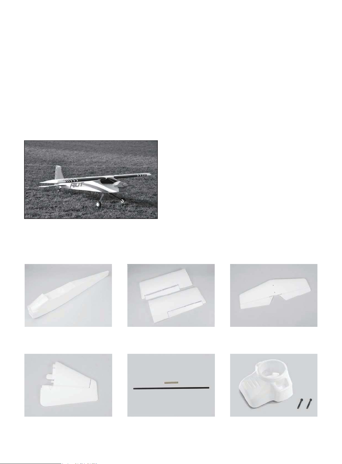
Spare parts list
A full range of spare parts is available for the Riot.Please contact your model dealer or visit
www.toprchobby.com for further details
NO: top04201
Fuselage
NO: top04202
Main wing set
NO: top04203
Horizontal wing
NO: top04204
Rudder
NO: top04205
Wing connection rod
NO: top04206
Cowl
Page 10
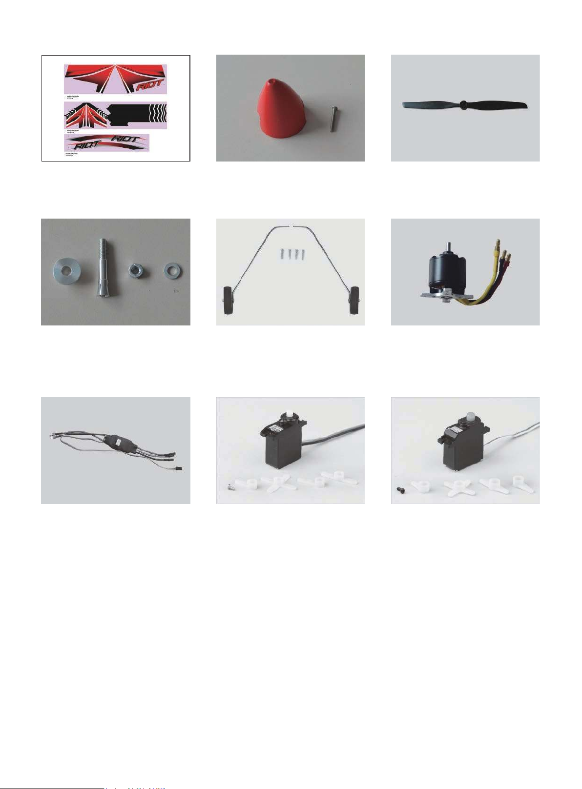
NO: top04207
Sticker(Red)
NO: top04208
Spinner
NO: top04209
Propeller(12 x 8)
NO: top04210
Propeller adaptor
NO: top04213
ESC 40A brushless
NO: top04211
Main landing gear
NO: top04214
Servo(9g,extension cable
length 435mm)
NO: top04212
Motor 3720-880KV
outer runner brushless
NO: top04215
Servo(17g,extension cable
length 180mm)
Page 11
RIOT
www.toprchobby.com
Tel: 0086-(0)755-27908315
Fax: 0086-(0)755-27908325
Made in China
 Loading...