

Page 1
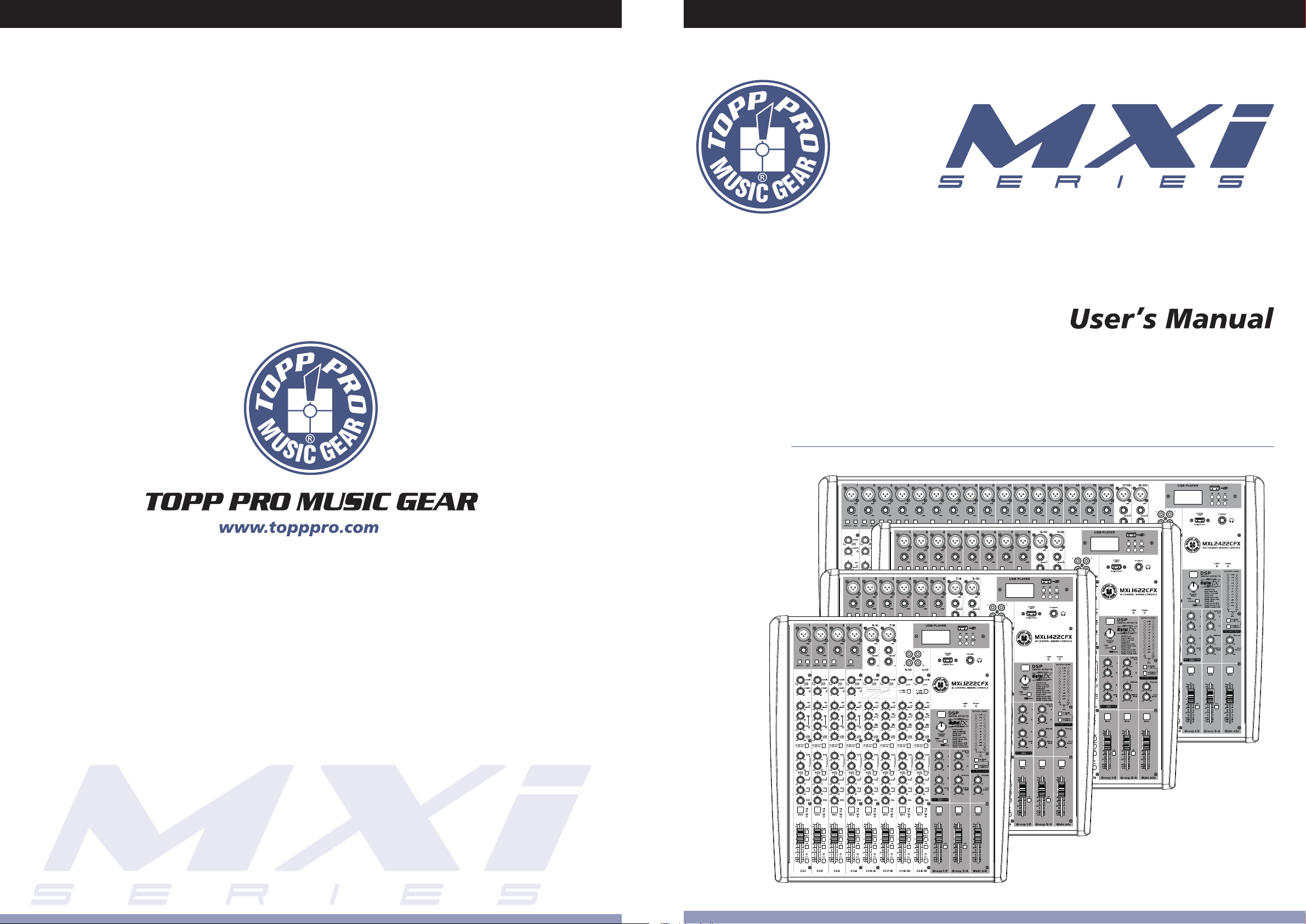
12 / 14 / 16 / 24 CHANNELS MIXING CONSOLE
NF05046-1.3
Page 2
Page 3
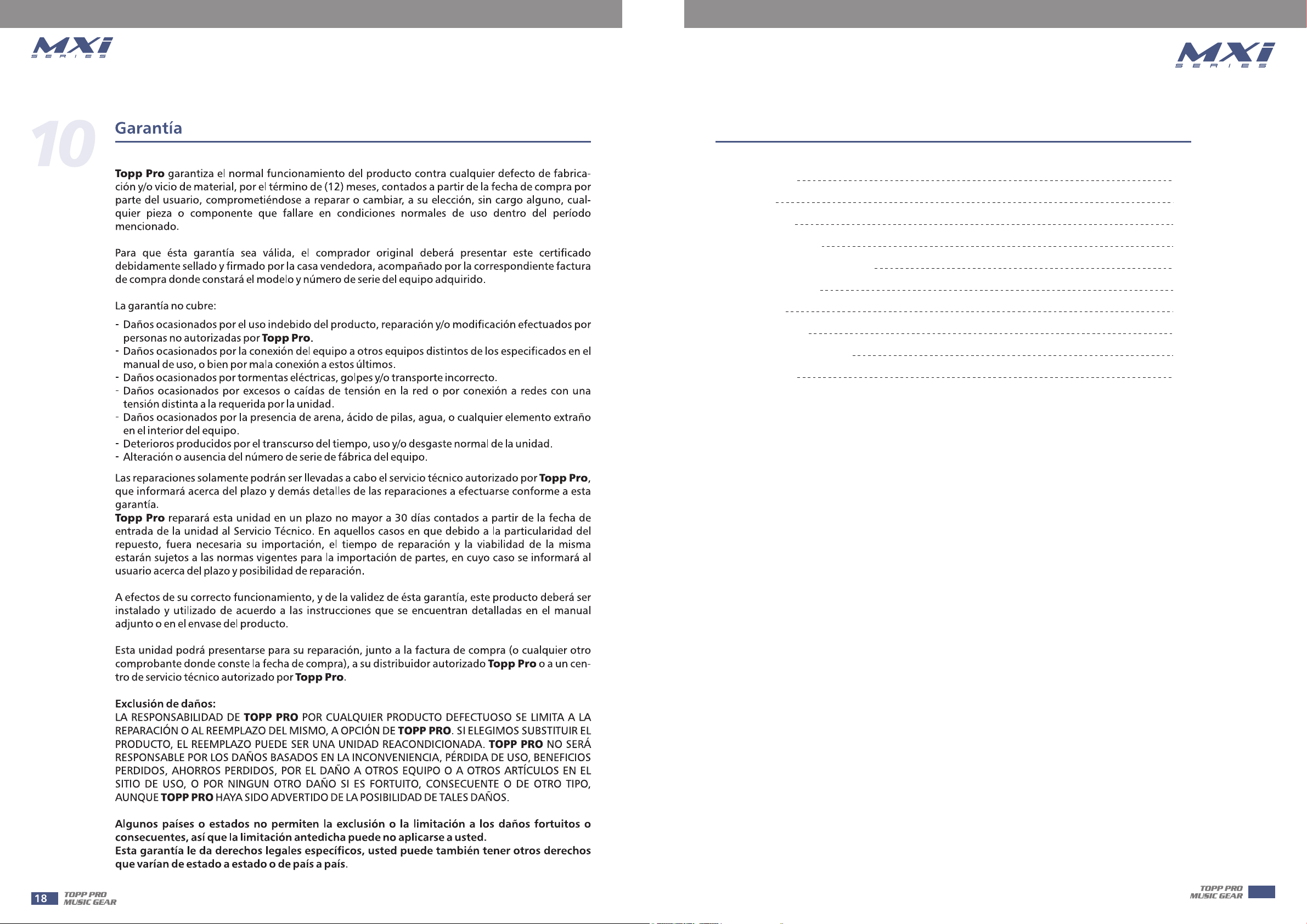
Table of Contents
1. Introduction
2. Features
3. Usefull Data
4. Control Elements
5. Installation And Connection
6. Hookup Diagram
7. Preset List
8. Block Diagram
9. Technical Specifications
10. Guarantee
MXi.1222CFX, MXi.1422CFX, MXi.1622CFX and MXi.2422CFX are Mixing Consoles for
professional use. They can be used in following electromagnetic environment: residential,
commercial and light industrial, urban outdoors. It is not intended for rack mounting.
4
4
4
5
13
14
15
16
17
18
This device complies with Part 15 of the FCC Rules. Operation is subject to the following two
conditions: (1) this device may not cause harmful interference, and (2) this device must accept
any interference received, including interference that may cause undesired operation.
FCC Statement:
"This equipment has been tested and found to comply with the limits for a Class B digital device,
pursuant to part 15 of the FCC Rules. These limits are designed to provide reasonable protection
against harmful interference in a residential installation. This equipment generates, uses and can
radiate radio frequency energy and, if not installed and used in accordance with the instructions,
may cause harmful interference to radio communications. However, there is no guarantee that
interference will not occur in a particular installation. If this equipment does cause harmful
interference to radio or television reception, which can be determined by turning the equipment
off and on, the user is encouraged to try to correct the interference by one or more of the
following measures:
—Reorient or relocate the receiving antenna.
—Increase the separation between the equipment and receiver.
—Connect the equipment into an outlet on a circuit different from that to which the receiver is
connected.
—Consult the dealer or an experienced radio/TV technician for help."
3
Page 4
Introduction
Thank you choosing for purchasing 12 / 14 / 16 / 24 Channel Mixing Console. This is a professional
compact mixer to give you great quality and better reliability than ever before you will get the
smooth, accurate more natural and open sound from this apparatus, and it is really ideal for gigs
,recording and fixed PA installations.
The 12 / 14 / 16 / 24 channel Mixing Console is packed with features that can not be found in
other consoles of its size: 4 / 6 / 8 / 16 mono which can provided with ultra low noise microphone
pre amplifiers and Phantom Power at +48 Volt; 4 stereo input channels; 3-band EQ with
sweepable MID on mono inputs;4-band EQ on stereo inputs, 4 auxiliary control, highly accurate
12-segment bar graph meters and 2-track inputs assignable to main mix ,control room/phone
output etc...
This unit is very easy to operate but we advise you to go through each section of this manual
carefully. In this way you will get the best out of your Mixing Console.
Features
• Ultra-low noise discrete MIC Preamps with +48V Phantom Power.
• 4 / 6 / 8 / 16 MIC Input Channels with XLRs and balanced Line Inputs.
• 4 / 6 / 8 Compressors control and 6 / 8 Insert I/O.
• Low Cut for each MIC Input.
• 2 Stereo Input Channels with mono XLRs Input and TRS Jacks;
2 Stereo Input Channels with RCA Jacks.
• 3-band EQ with sweepable MID and Peak LEDs on each Mono channels. 4-band EQ and
Peak LEDs on Stereo channels.
• AUX 1 & AUX 2 Send POST/PRE per channel for monitoring or external effects.
AUX 3 & DFX Send POST Fader for internal effects or monitoring.
• PFL/Mute function for each channels, 60mm Fader for level control.
• GR1/2, GR3/4 and Main L-R bus assign for each channel.
• Balanced XLR & TRS outputs for Main Mix.
• Built in 24-bit DSP effect with 100 presets.
• Assembled MP3 Player.
• Internal switch-mode power supply for maximum flexibility 100-240V.
• With USB port, record from MAIN OUT and play to CH9/10 & CH11/12 & CH13/14 & CH21/22.
Usefull Data
Please write your serial number here for future reference.
4
(T1.6A AC250V para 24 canales)
(40 watts para 24 canales)
Page 5
Control Elements
The following features will be applied to 12 channels,14 channels,16 channels and 24 channels.
In case where different features need to be described for each other, the unit 12 channels and 14
channels will be descried first, followed by the unit 16 channels and 24 channels feature in
brackets.
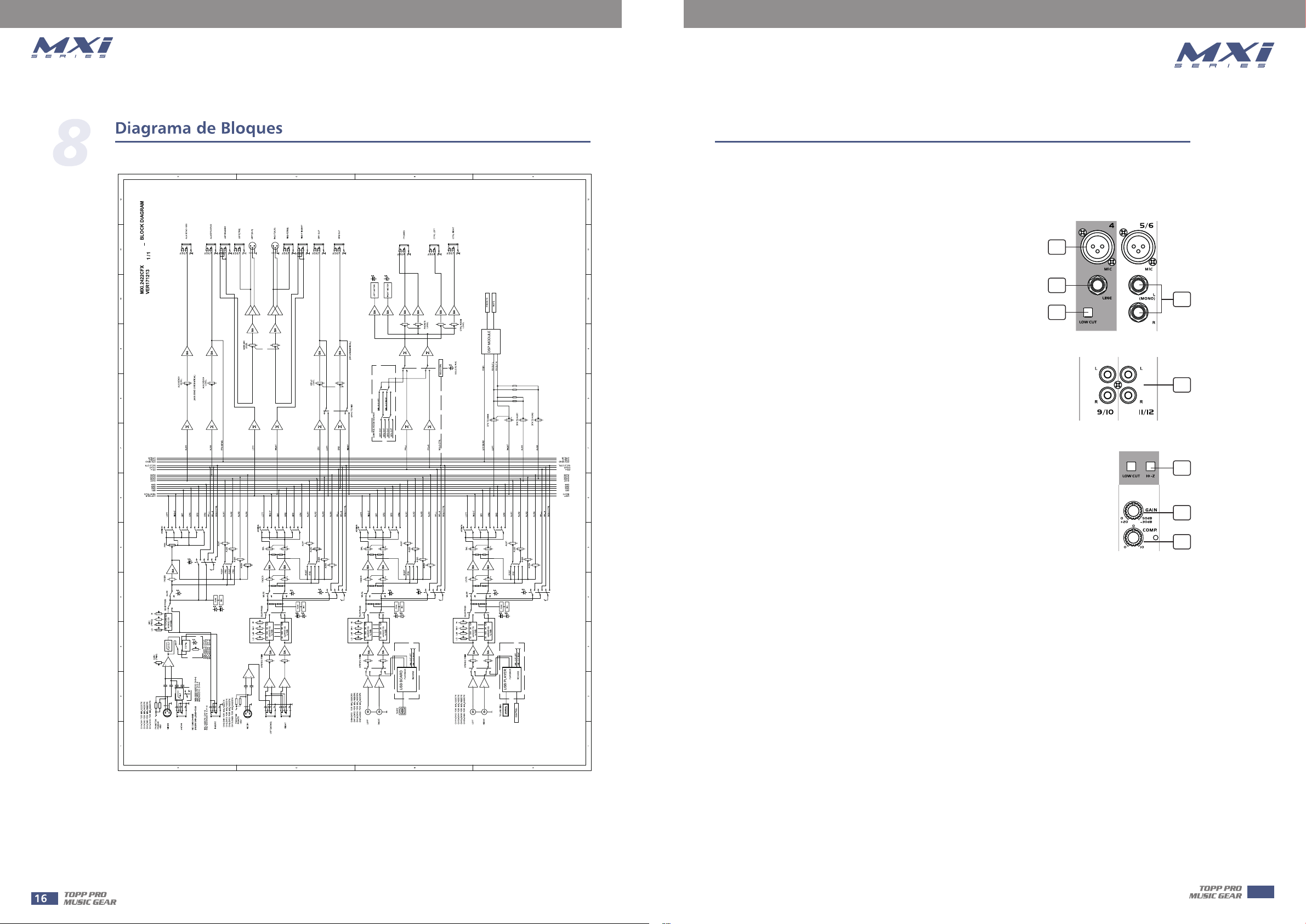
1. MIC INPUT JACKS ( CH 1 to 7/8 for 12 channels or CH 1 to
9/10 for 14 channels or CH 1 to 11/12 for 16 channels or CH 1
to 19/20 for 24 channels)
These are balanced XLR-type microphone input jacks
2. LINE INPUT JACKS ( CH 1 to 4 for 12 channels or CH 1 to 6
for 14 channels or CH 1 to 8 for 16 channels or CH 1 to 16 for
24 channels )
These are balanced TRS phone-jack line inputs.
You can connect either balanced or unbalanced phone plugs to
these jacks.
3. LINE INPUT JACKS ( CH 5/6 to 7/8 for 12 channels or CH 7/8
to 9/10 for 14 channels or CH 9/10 to 11/12 for 16 channels or
CH 17/18 to 19/20 for 24 channels )
They are organized in stereo pair and provided with 1/4" TRS
sockets. It is used to connect the stereo device, plug both the left
input and the right input. Using the left input if connect a mono
input signal to the stereo channel, the output signal will appear
on both sides.
4. LOW CUT
By pressing this button you will activate a 75Hz low frequency filter with a slope of 18dB per
octave. You can use this facility to reduce the hum noise infected by the mains power supply, or
the stage rumble while using a microphone.
1
2
3
4
5
6
7
8
4
5. RCA INPUT JACKS ( CH 9/10 to 11/12 for 12 channels or 11/12 to 13/14 for 14 channels or
CH 13/14 to 15/16 for 16 channels or CH 21/22 to 23/24 for 24 channels)
They are organized in stereo pair and provided with RCA sockets. It is used to connect the stereo
device, plug both the left input and the right input.
6. HI-Z
To change to a high impedance input, push the appropriate hi-z switch.
7. GAIN CONTROL
Adjusts the input signal level. To achieve the best balance between S / N and dynamic range,
adjust the level so that the peak LED indicator lights occasionally only on the highest input
transients. For each channel the MIC input adjustment range of the Gain is 0 to 50dB and the
sensitivity of line input is +20 to -30dB.
8. COMP CONTROL
Adjust the amount of compression applied to the channel. Turn the knob to the right to increase
the compression ration and the output gain will automatically adjusted. The result is smoother,
more even dynamics because louder signals are attenuated which the overall level is boosted.
5
Page 6
Control Elements
4
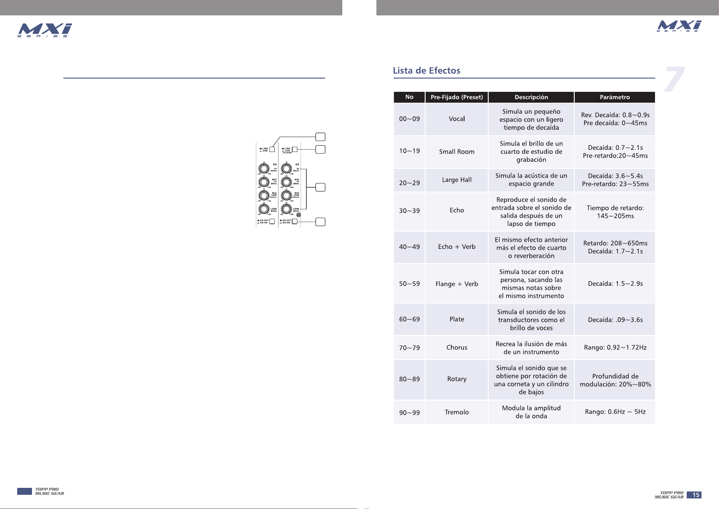
9. LINE/USB
By pressing this button, it will switch to the USB mode, then the USB signal can be sent to this
channel; by releasing this button, the LINE IN inputs signal will send to the line input channels.
10. LINE/USB PLAYER
by pressing this button, it will switch to the USB PLAYER mode,
then the signal of USB PLAYER module sent to this channel;
11. EQUALISER CONTROLS
There are 3-band EQ with sweepable MID on all mono input
channel 1-4/1-6/1-8/1-16: HI, MID and LOW band. There are
4-band fixed frequency EQ on the stereo channel
5-12/7-14/9-16/17-24: HI, HI- MID, MID-LOW and LOW band. All
bands provide up to 15 dB of boost or cut.
--HI
If you turn this control up, you will boost all the frequencies above
12 kHz (shelving filter). You will add transparency to vocals and
guitar and also make cymbals crispier. Turn the control down to
cut all frequencies above 12 kHz In such way, you can reduce
sibilances of human voice or reduce the hiss of a Tape player.
9
10
11
12
--MID
This is a peaking filter and it will boost/cut frequencies from 100 Hz to 8 kHz depending on the
position of the MID freq control. This control will affect especially upper male and lower female
vocal ranges and also the harmonics of most musical instruments.
--HI-MID
This control gives you up to 15 dB boost or cut at 3 kHz. It is useful for controlling voice. It can
accurately polish your performance via adjusting this knob.
--MID-LOW
This control gives you up to 15 dB boost or cut at 500 Hz.
--LOW
If you turn this control up, you will boost all frequencies below 80 Hz. You will give more punch
to bass drum and bass guitar and make the vocalist more "macho". Turn it down, you will cut all
the frequencies below 80 Hz. In this way, you can avoid low frequency vibrations and resonance
thus preserving the life of your woofers.
12. EQ SWITCH
This switch allows the user to use the EQ Section in signal path. Of course it can be used to make
A/B comparisons between equalized signal and not equalized signal.
It also can be used to apply equalization at a certain point of the show, excluding it when it's not
necessary.
6
Page 7
Control Elements
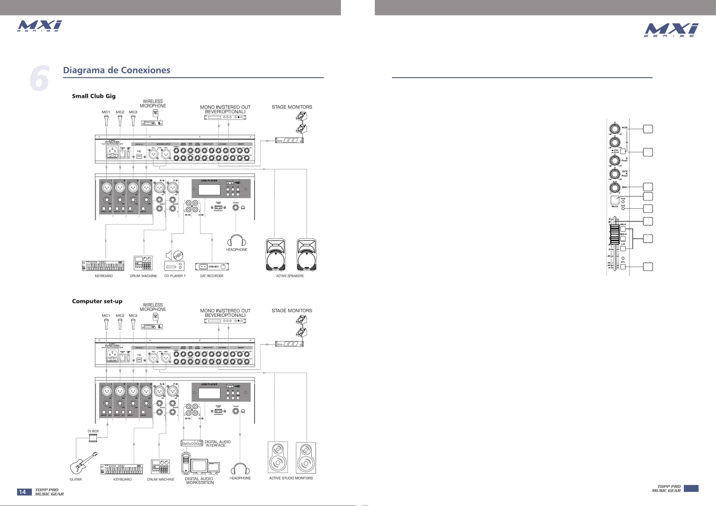
13. AUX SEND CONTROLS
These four controls are used to adjust the level of the respective signal sent to AUX bus and
their adjustable range is from -∞ to +10 dB .
14. PRE/POST
AUX1 and AUX2 can be switched to PRE/POST-FADER via the PRE/POST
button, so, generally, they can be used for monitor application and effects
& sound processors input. AUX3 and AUX4 are configured as POST-Faders.
15. PAN / BAL CONTROL.
The PAN control determines the stereo positioning of the channel signal on
the stereo L and R buses.The BAL control knob sets the balance between
left and right channels. Signal input through the stereo L/R bus.
16. MUTE
Each channel is equipped with the MUTE button, pressing this button is
equal to turning the fader down, which can mute the corresponding
channel output except for the PRE AUX sends, channel INSERT send and
PFL, and the MUTE LED will illuminate.
17. SIG/CLIP
Indicate that the channel's incoming audio signal is with in an optimal
range.
13
14
15
16
17
18
19
20
4
18. CHANNEL LEVEL
This fader will adjust the overall level of this channel and set the amount of signal sent to the
main output.
19. GR1-2/GR 3-4/L-R
Each channel provides three push-buttons: GR1-2, GR3-4, L-R . The three buttons can be
considered as signal assignment switches. Pressing the GR1-2 will assign the channel signal to
GROUP1-2, you can depend on the PAN switch to adjust the amount of channel signal sent to the
GR1versus GR2, when turns the PAN to completely left, then the signal can be only controlled
by GROUP1 and viceversa. In the same way, pressing the GR3-4 or L-R will assign the channel
signal to GROUP3-4 or MAIN MIX L-R, and will also be affected by PAN.
20. PFL
Each channel is equipped with the PFL button, pressing this button which the corresponding
signal send will be routed to CTRL ROOM/PHONES outputs and METER display.
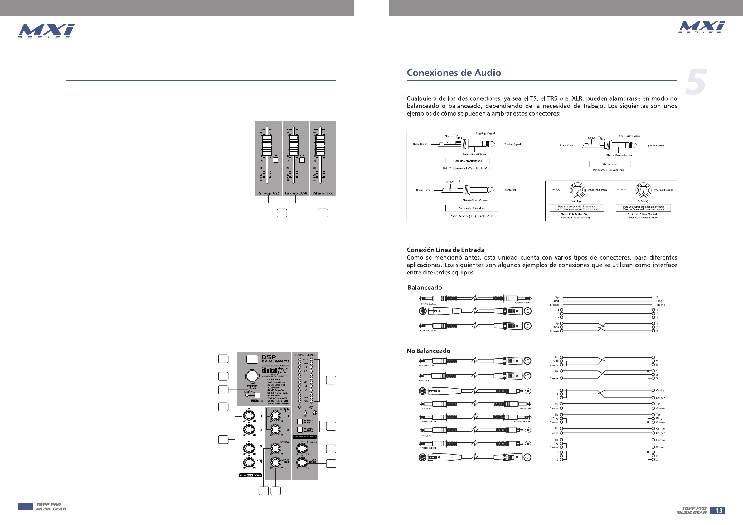
21. GROUPS LEVEL
These faders are used to control the levels of the signal send to the GROUPS OUT, the
adjustable range goes from -∞ to +10 dB. Any channel that is assigned to the groups, not muted
and not turned down will be assigned to the GROUPS OUT.
7
Page 8
Control Elements
4
22. MAIN MIX LEVEL
This fader is used to set the amount of signal sent to the main mix output.
23. DIGITAL EFFECTS
It displays the selected preset.
24. PROGRAM(PUSH)
Adjust this knob to select the right effect you wish to perform.
There are totally 100 options for you: Echo, Vocal, Plate and
versatile two-effect combination.
When you are satisfied the right preset, please push this knob
to store this preset you want.
25. DFX/MUTE
Disables the internal effects processor; in this case the red
"PEAK" LED will be lit permanently.
26. DFX TO AUX SEND1/2
The both rotary knobs assign the DFX signals to their respective AUX SEND outputs.
27. AUX SEND CONTROLS
These four controls are used to determine the master AUX SEND levels, which can be varied from
-∞to +10 dB. When the external effect units which have no input gain control were connected to
mixer, you can get a further +10 dB gain available from these Aux Send outputs.
As to the AUX4, it can also provide the lovable level adjustment for the internal effect signal.
21 22
28. DFX OUT
These control is used to determine the internal DSP module levels and DFX sends output, which
can be varied from -∞ to +10dB
29. DFX TO MAIN
This control is used to assign the signal from FX to
MAIN MIX output.
30. OUTPUT LEVEL
This stereo 12 segments LED meter will be
indicate the level of overall output signal.
31. MAIN/GR
If you release the MAIN/GR button, the signal will
be cone from the MAIN MIX output, it will not be
affected by pressing both GR1/2 and GR3/4
button. When you push down the MAIN GR
button and press both GR1/2 and GR3/4 at the
same time, the signal will be come from the GR3/4
output. When you release the GR1/2 and GR3/4,
the signal will be come from the GR1/2 output.
23
24
25
26
27
30
31
32
33
28 29
8
Page 9
Control Elements
12/14/16/24
32. PHONES CONTROL
This control is used to adjust the signal present at the Phones output, which can be varied from
-∞ to +10 dB.
33. CONTROL ROOM CONTROL
This control is used to adjust the signal present at the control room output, which can be varied
from -∞ to +10 dB.
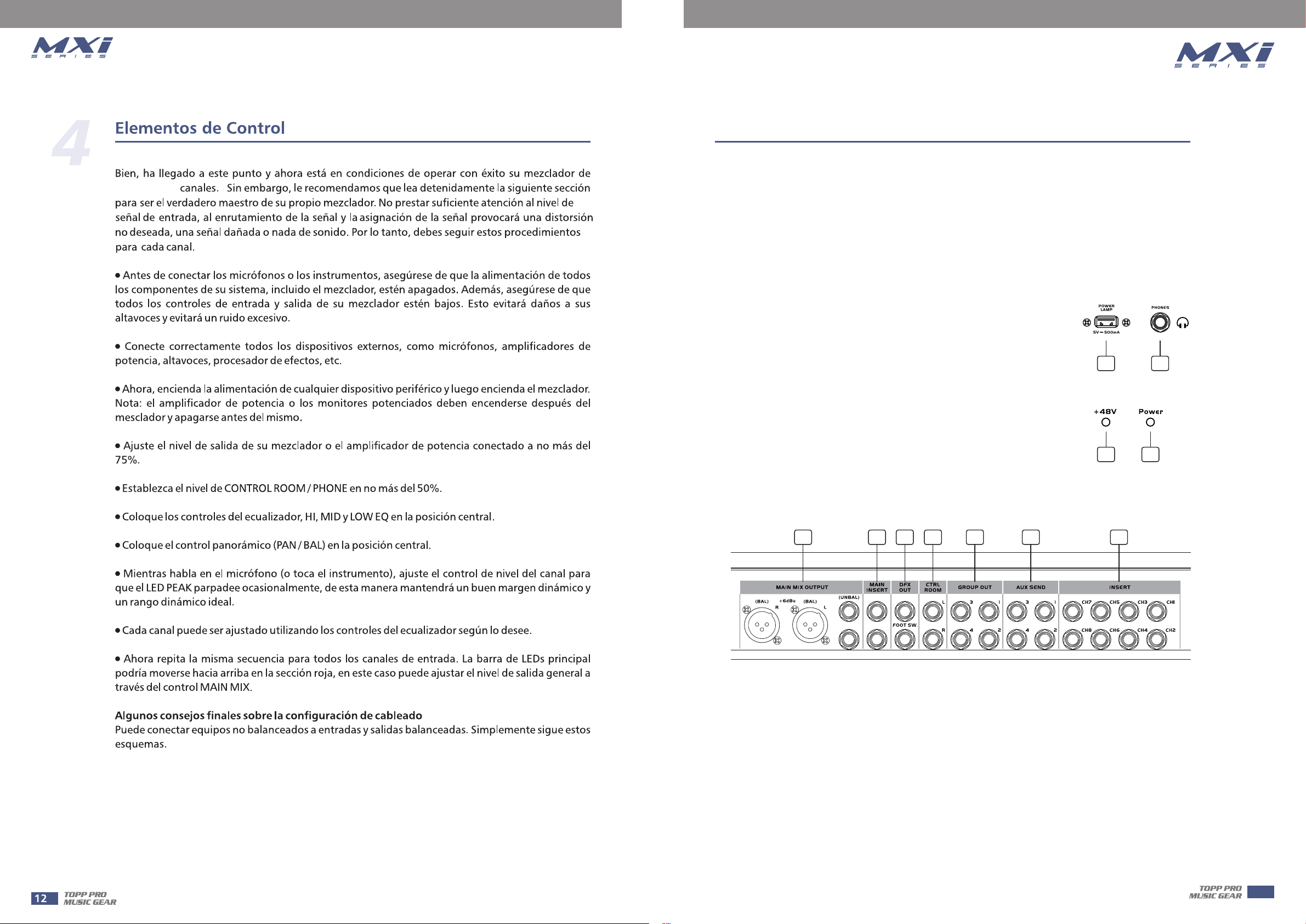
34. POWER LAMP socket
This lovable LAMP is very convenient for your operation, it is located
in the top right corner of the front panel, and provides the 5V socket
that can drive standard USB-type lamp.
35. PHONES
This socket will be used to send out the mix signal to a pair of
headphones.
36. PWR LED
This LED indicates when the power is on in your mixer.
37. +48V LED
This LED indicates when the phantom power is switched on.
34 35
37 36
4
38 39 40 41 42 43 44
38. MAIN MIX OUTPUT
These stereo outputs are supplied with both the XLR and 1/4" phone jacks and it is controlled by
the Main Mix Level.
39. MAIN INSERT
These two 1/4" phone jacks are stereo insert points and used to connect processors such as
compressors, equalisers etc.. When insert a external processor into the jack, the Main stereo
signal will be taken out after the main bus and returned into the MAIN MIX output before the
MAIN MIX fader.
9
Page 10
Control Elements
4
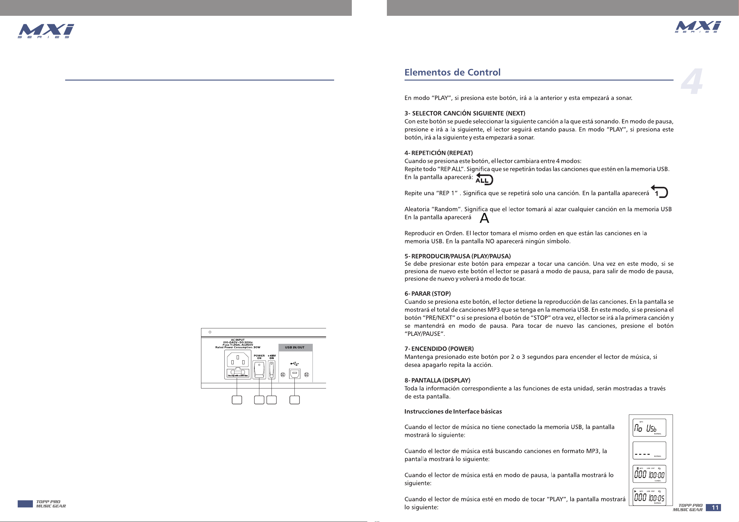
40. DFX OUT
This 1/4" sockets are used to send the signal from DFX mix buses to external devices.
FOOTSW.
This socket is used to connect external footswitch for your convenient operation, it has the same
function as DFX MUTE button.
41. CTRL-ROOM
These 1/4" phone sockets will be used to send the signal to studio monitor speakers or to a second
set of PA.
42. GROUP OUT
These 1/4" TRS jack are used to send out the signal from the GROUP 1/4 mix bus to external
devices.
43. AUX SENDS
These 1/4" phone sockets are used to send out the signal from the AUX bus to external devices
such as effects.
44. INSERT
This is where you connect external sound processors such as compressor-limiter, equalizers, etc..
45. AC Inlet with FUSE Holder
Use it to connect your mixer to the main AC with the supplied AC cord. Please check the voltage
available in your country and how the voltage for your miser is configured before attempting to
connect your mixer to the main AC.
46. POWER Switch
This switch is used to turn the main
power on and off.
47. +48 Volt Phantom Power Switch
It is available only to the XLR MIC sockets.
Never plug in a microphone when phantom
power is already on. Before turning
phantom power on, make sure that all
faders are totally down. In this way, you will
protect your stage monitors and main
loudspeakers.
48. USB PORT
This USB port is used to connect the unit to PC with a transmission line. When it is in RECORD
mode, it can connect with the MAIN MIX output; in the PLAYBACK mode, it can connect with the
last stereo channel 9/10 or channel 11/12 or channel 13/14 or channel 21/22.
45 46 47 48
10
Page 11
Control Elements
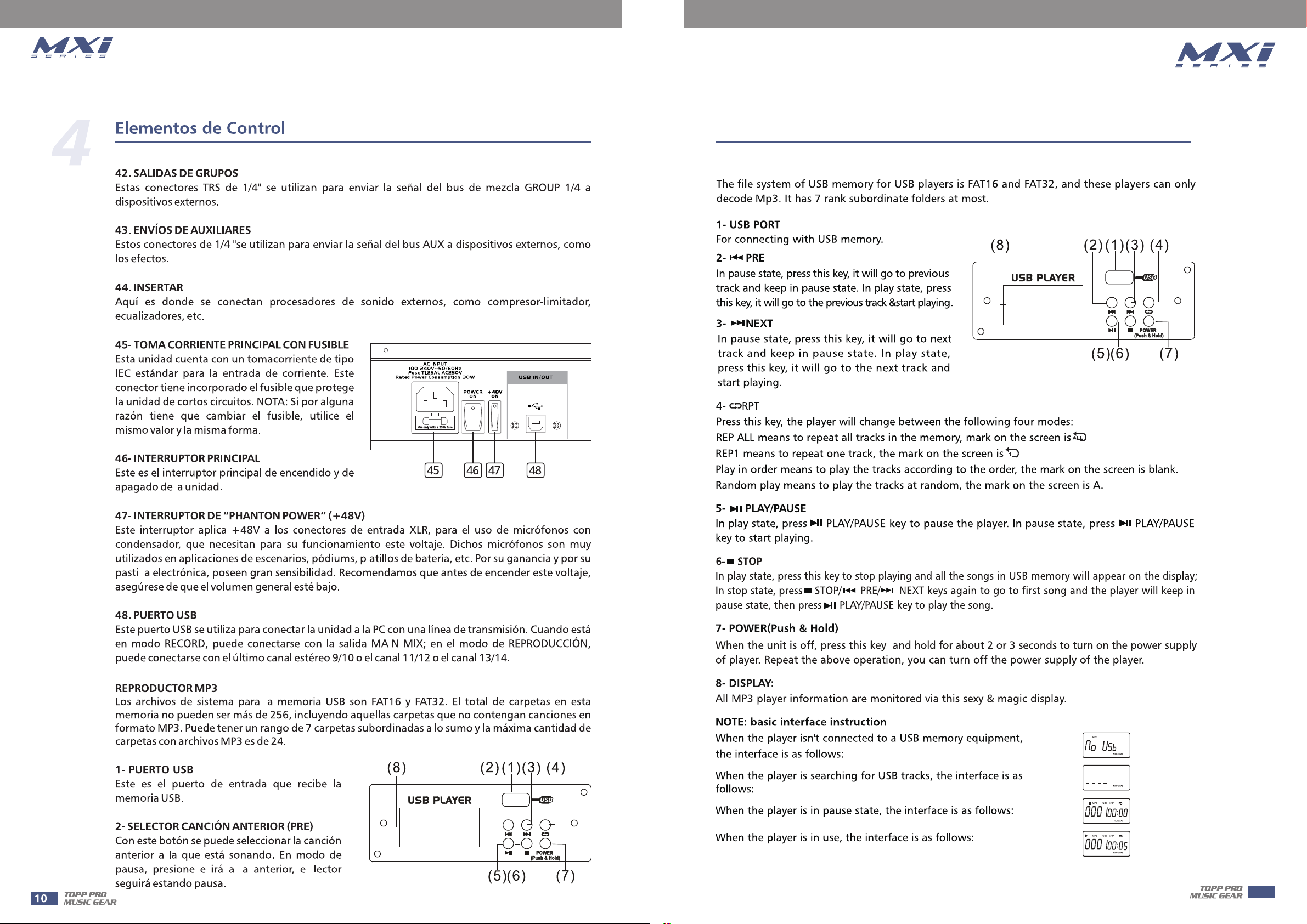
MP3 PLAYER
4
11
Page 12
Control Elements
4
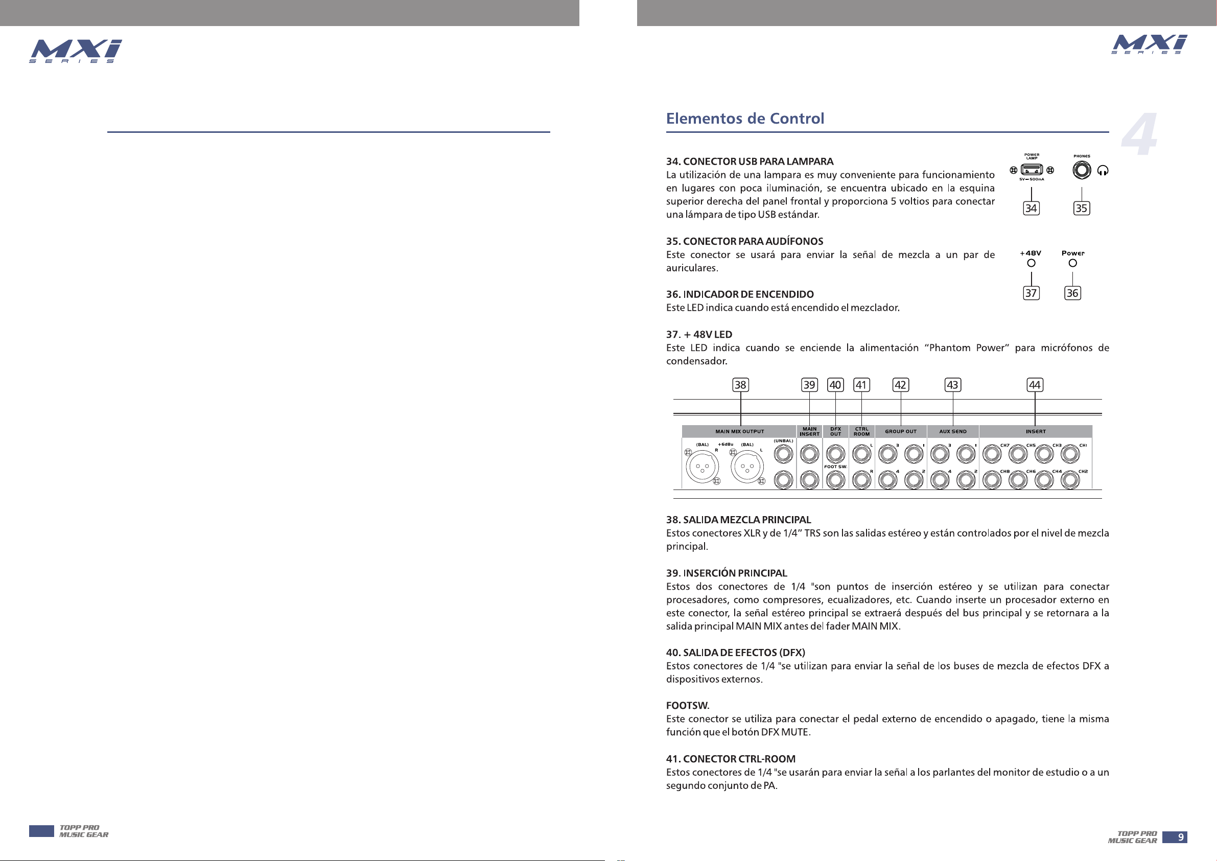
Ok, you have got to this point and you are now in the position to successfully operate your 12 /
14 / 16 / 24 Channel Mixing Console. However, we advise you to read carefully the following
section to be the real master of your own mixer. Not paying enough attention to the input signal
level, to the routing of the signal and the assignment of the signal will result in unwanted
distortion, a corrupted signal or no sound at all. So you should follow these procedures for every
single channel:
• Before connecting MICs or instruments, make sure that the power of all your systems
components including the mixer is turned off. Also, make sure that all input and output
controls of your mixer are turned down. This will avoid damage to your speakers and avoid
excessive noise.
• Properly connect all external devices such as MICs, power amplifiers, speakers, effect processor
etc.
• Now, turn on the power of any peripheral devices, then power up the mixer.
Note: the power amplifier or powered monitors shall be turned on after the mixer and turned off
before the mixer.
• Set the output level of your mixer or the connected power amplifier at no more than 75%.
• Set the CONTROL ROOM/PHONE level at no more than 50%.
• Position HI, MID and LOW EQ controls on middle position.
• Position panoramic (PAN/BAL) control on center position.
• While speaking into the MIC (or playing the instrument ), adjust the channel Level control so
that the PEAK LED will blink occasionally, in this way you will maintain good headroom and
idea dynamic range.
• You can shape the tone of each channel by adjusting the equalizer controls as desired.
• Now repeat the same sequence for all input channels. The main LED could move up into the red
section, in this case yo can adjust the overall output level through the MAIN MIX control.
Some Final Tips on Wiring Configuration
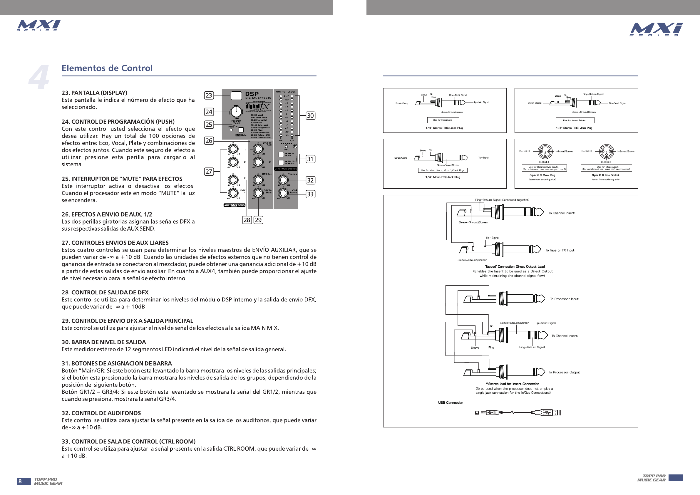
You can connect unbalanced equipment to balanced inputs and outputs. Simply follow these
schematics.
12
Page 13
Installation And Connection
5
13
Page 14
6
Hookup Diagram
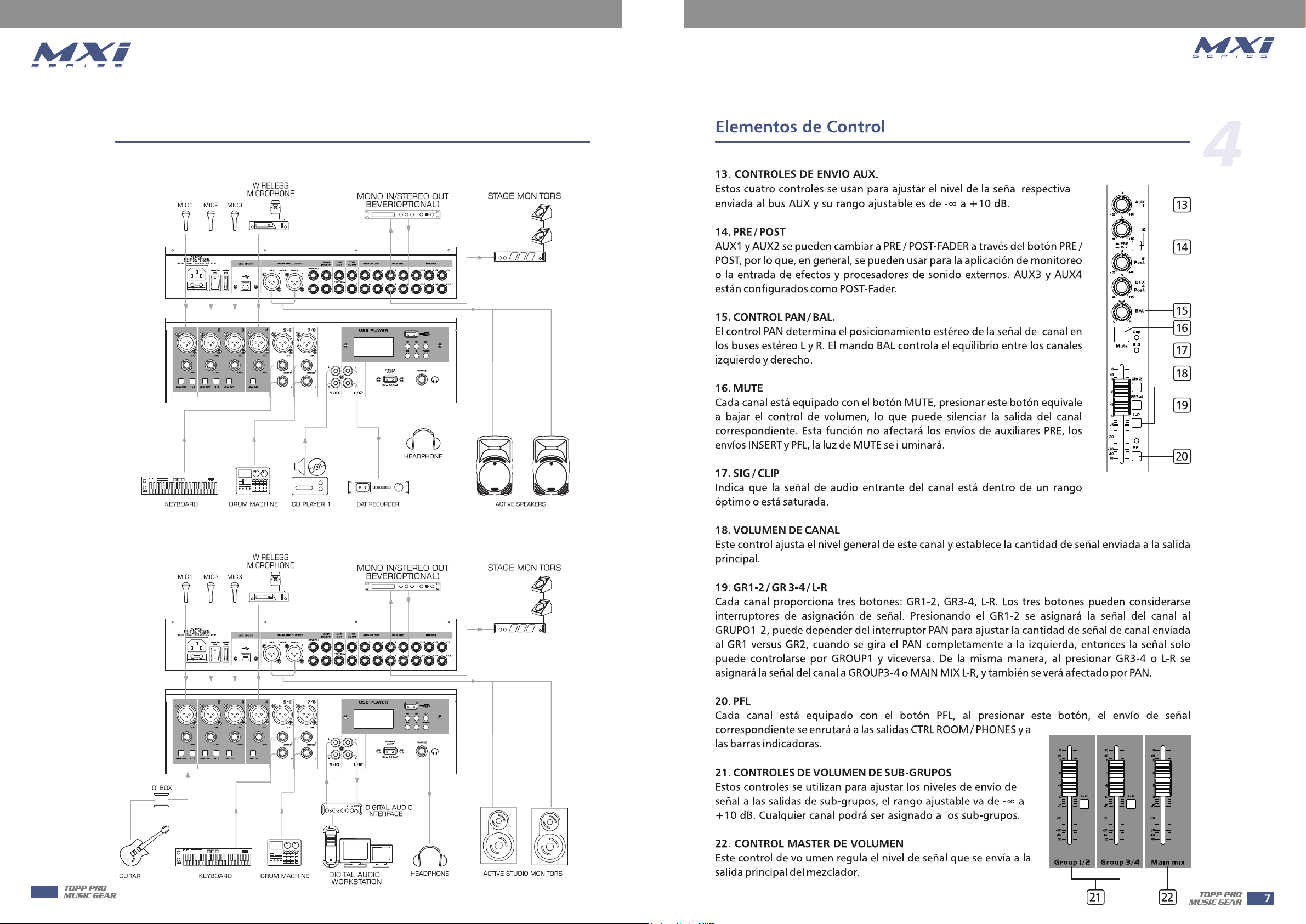
Small Club Gig
Computer set-up
14
Page 15
/1-8/1-16.
/9-16/17-24
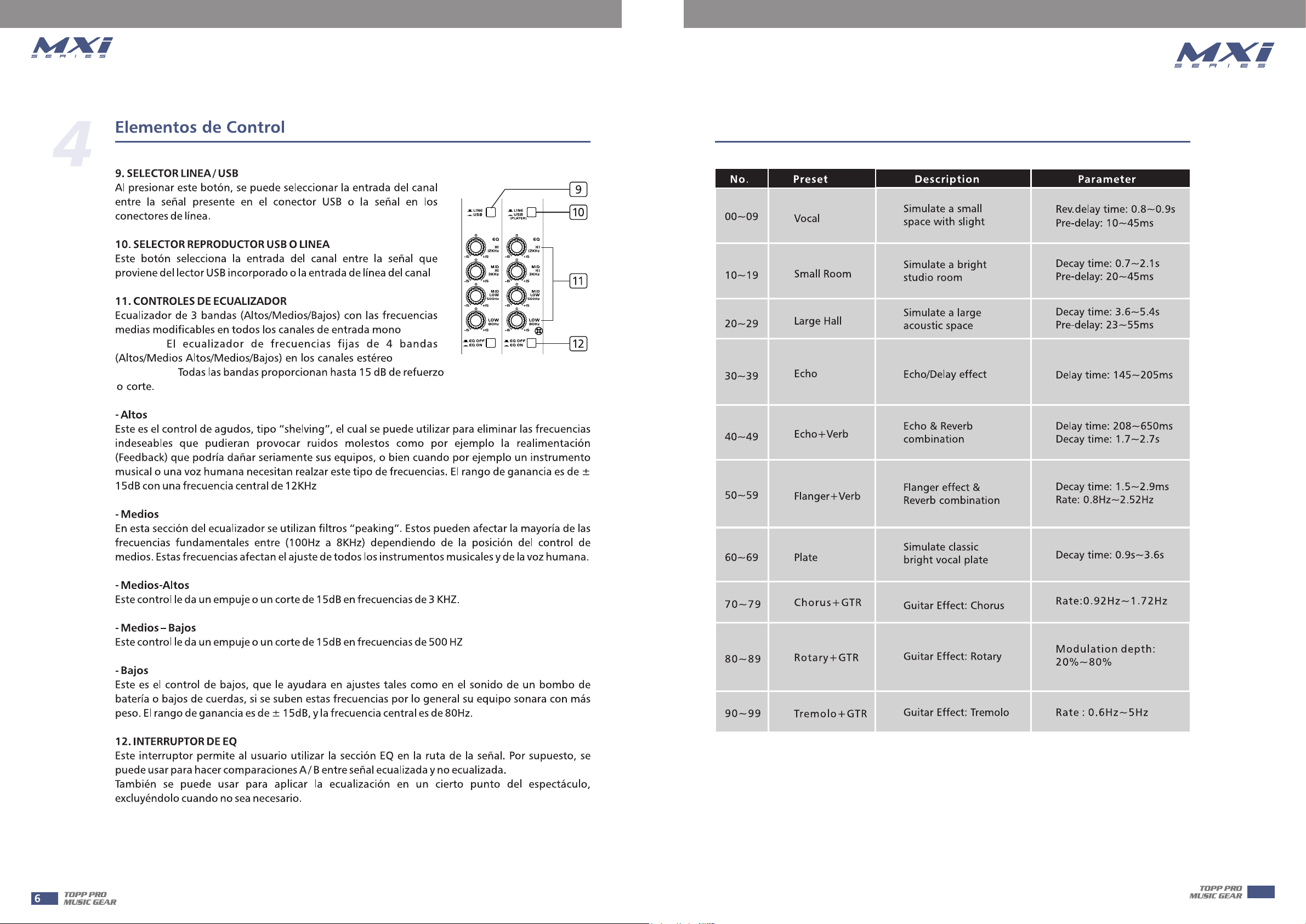
Preset List
7
1-4/1-6
5-12/7-14
15
Page 16
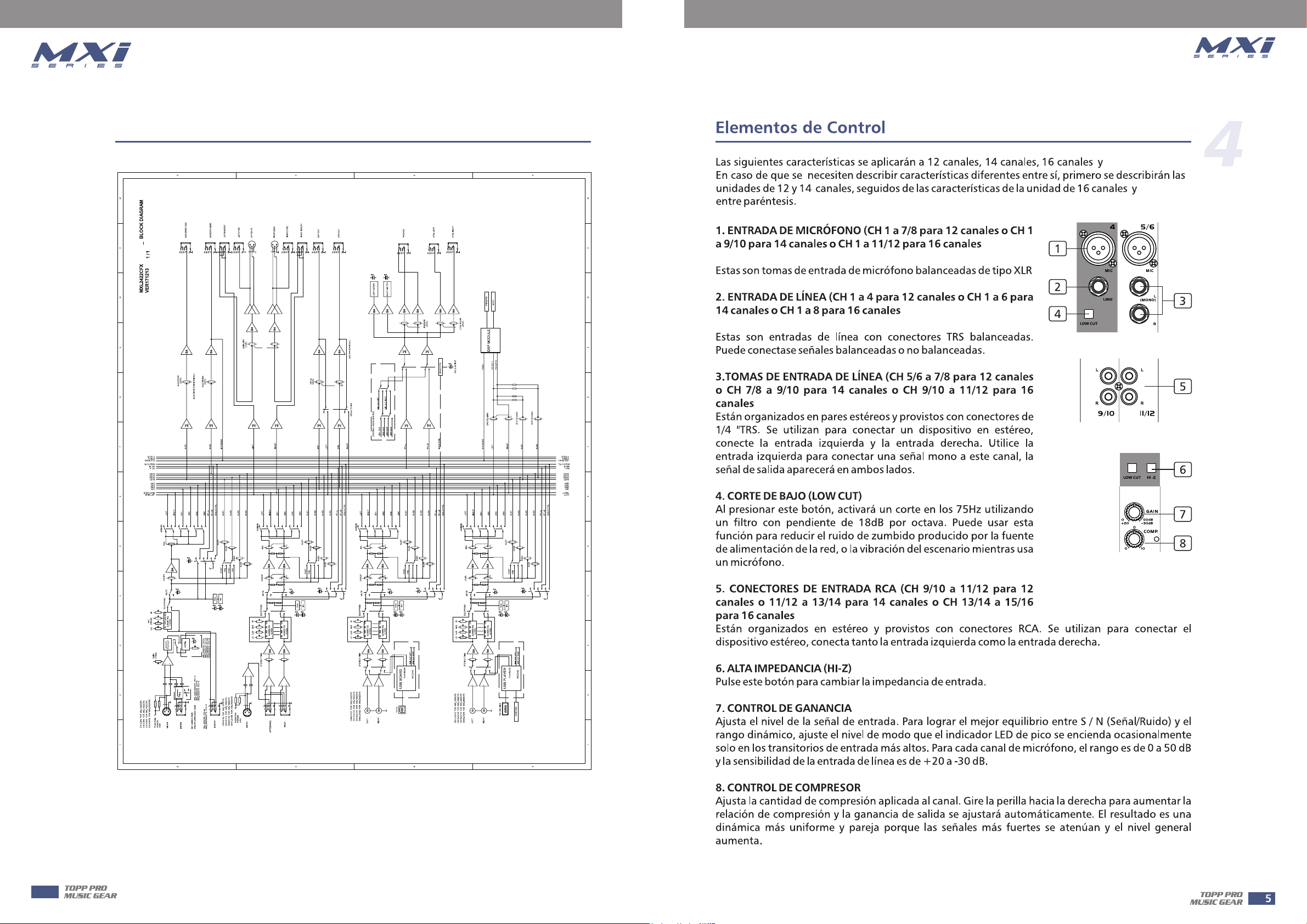
Block Diagram
8
24 canales.
24 canales
o CH 1 a
19/20 para 24 canales)
o CH 1 a 16 para 24
canales)
o CH 17/18 a 19/20 para 24 canales)
16
o CH 21/22 a 23/24 para 24 canales)
Page 17
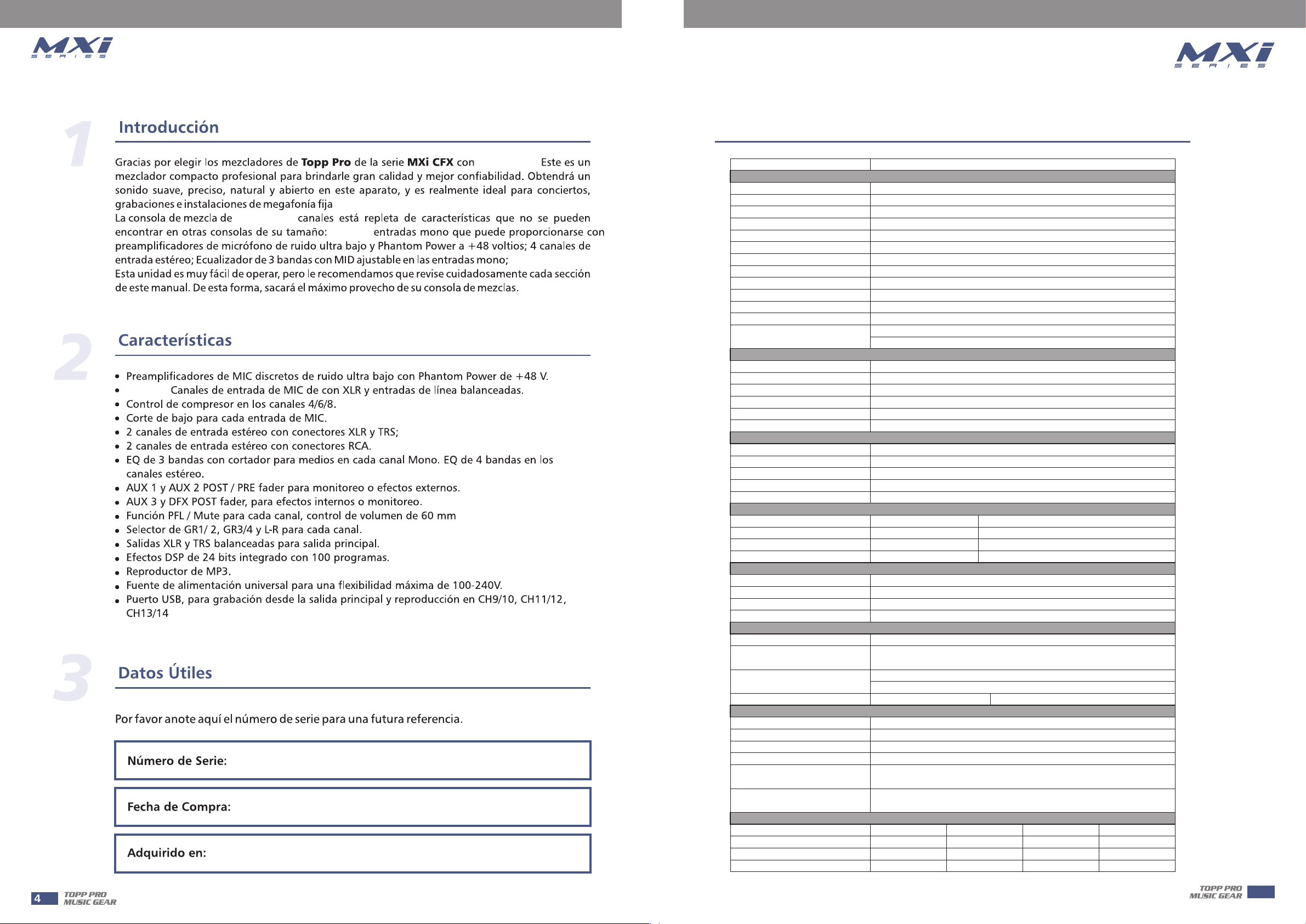
Technical Specifications
4/6/8/16
y CH21/22.
12/14/16/24
4/6/8/16
12/14/16/24.
MODEL :
Mono channels
Microphone input
Frequency response
Distortion(THD+N)
Gain range
Max. Input
LOW CUT
SNR
Phantom power
Line input
Frequency response
Distortion(THD+N)
Sensitivity range
COMPRESSOR
Stereo input channels
Mic input
Line input
Frequency response
Distortion(THD+N)
Sensitivity range
SNR
RCA input channels
RCA input
Frequency response
Distortion(THD+N)
Sensitivity range
SNR
Channels EQ
High
Mid
Low
Impedances
Microphone input
All other input
Tape out
All other out
DSP section (options)
A/D and D/A converters
Type of effects
Controls
FOOT-SW
Main mix section
Max. MAIN MIX output
AUX range
Fader range
PHONES/CONTROL-ROOM range
Hum & Noise
Crosstalk
Power supply
Main voltage
Fuse
Rated power consumption
12 / 14 / 16 / 24 channel mixing console
XLR with balanced
10Hz to 55KHz,+/-3dB
<0.03% at +0dB ,22Hz~22KHz A-weighted
0dB to 50dB
+21 dB
75Hz
<-100dBr A-weighted
+48V with switch control
1/4” TRS with balanced
10Hz to 55KHz,+/-3dB
<0.03% at +0dB ,22Hz~22KHz A-weighted
+20dB~ -30dB
GAIN:0~9dB
THRESHOLD:20dB--->5dB
XLR with balanced
1/4' TRS with balanced
10Hz to 55KHz,+/-3dB
<0.03% at +0dB ,22Hz~22KHz A-weighted
+20dBu~ -30dBu
<-100dBr A-weighted
RCA with un-balanced
10Hz to 55KHz,+/-3dB
<0.03% at +0dB ,22Hz~22KHz A-weighted
+20dBu~ -30dBu
<-100dBr A-weighted
Mono Channel
+/-15dB @12KHz
+/-15dB @100KHz -8KHz
+/-15dB @80Hz
1.8K Ω
10KΩ or greater
1KΩ
120Ω
24bit
Vocal, Small Room, Large Hall, Echo, Echo+Verb, Flange+Verb,
Plate, Chorus+GTR, Rotary+GTR, Tremolo+GTR
100 position preset selector(10 preseter * 10 variation)
Mute switch & Foot-switching with LED indicator
TIP:FX
+26dBu XLR balanced (+20dBu un-balanced)
OFF to +10dB
OFF to +10dB
OFF to +10dB
<-80dB @ 20Hz~22KHz A-weighted, 1 channel & MAIN
level:0dB, the other: Minimum
<-80dB @0dB 20Hz~22KHz A-weighted,MAIN level:0dB,
the other :minimum,
12 channels
100-240V~ 50/60Hz
T1.25A AC250V
30W
14 channels 16 channels
100-240V~ 50/60Hz
T1.25A AC250V
30W
Stereo Channel
+/-15dB @12KHz
+/-15dB @3KHz or +/-15dB @500Hz
+/-15dB @80Hz
SLEEV: GND
100-240V~ 50/60Hz
T1.25A AC250V
30W
9
24 channels
100-240V~ 50/60Hz
T1.6A AC250V
40W
17
Page 18
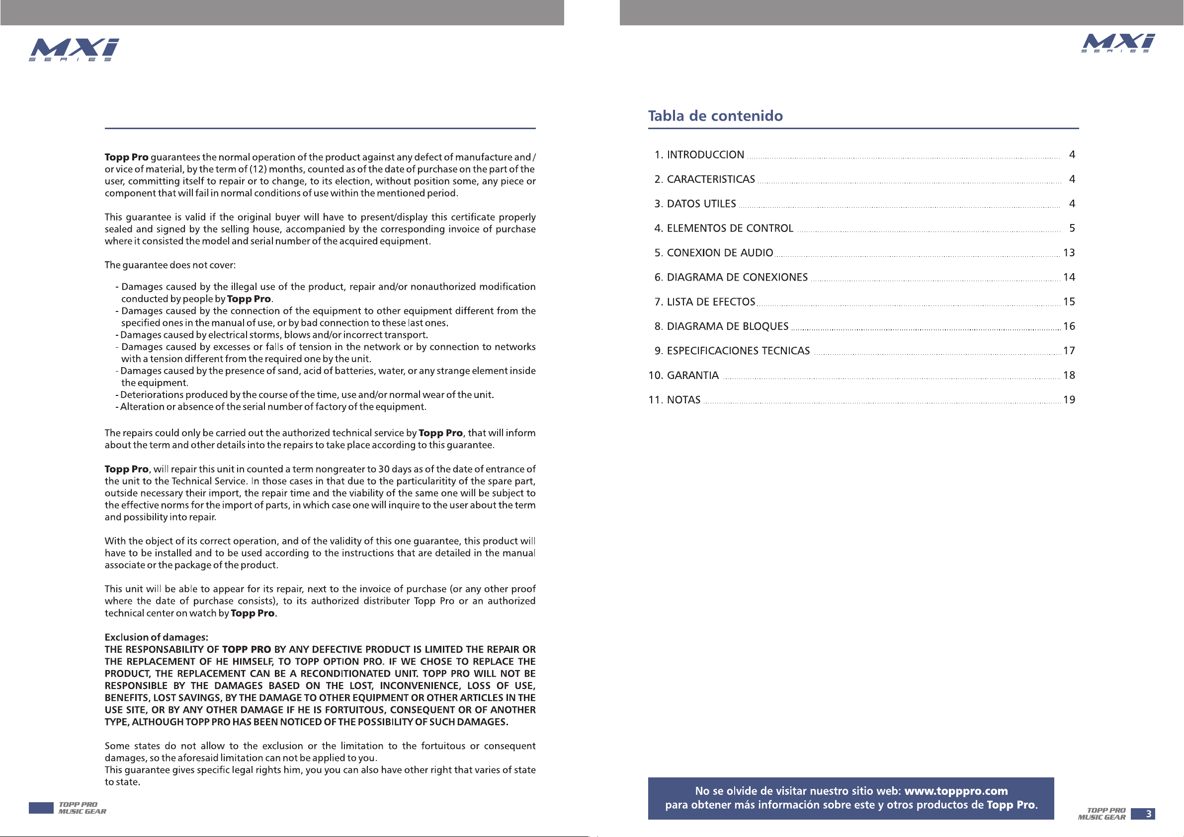
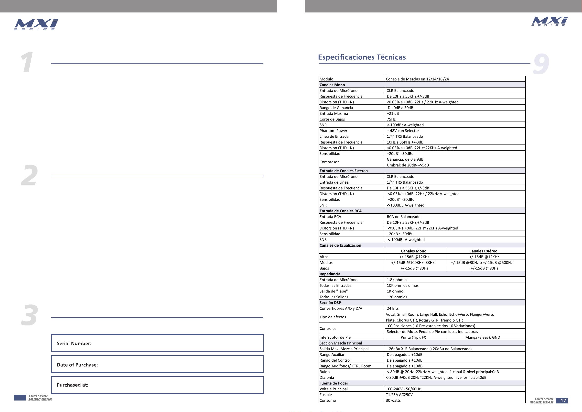
10
Guarantee
18
Page 19
Notes
11
19
Page 20
16/24
Page 21
20
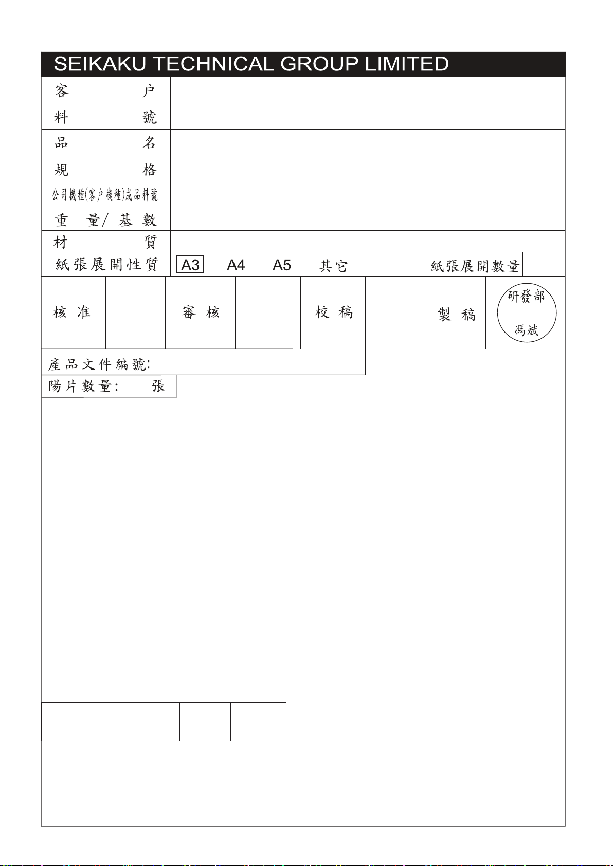
TOPP PRO
NF05046
說明書-英西文
MXi.12 14 16 24 CHANNELS_V1.3
MXi.1222CFX
0.1kg/1
銅板紙
10pcs
2018.02.25
修改紀錄 版本 更改者 日期
依工程師要求增加FCC語句在 2P頁面 1.3 馮斌 2018.02.25
變更單號: QHFBE004-20180200005
 Loading...