

Toppro T2208 User Manual
16 mic preamplifiers with dedicated trim control
T2208
Volume
2

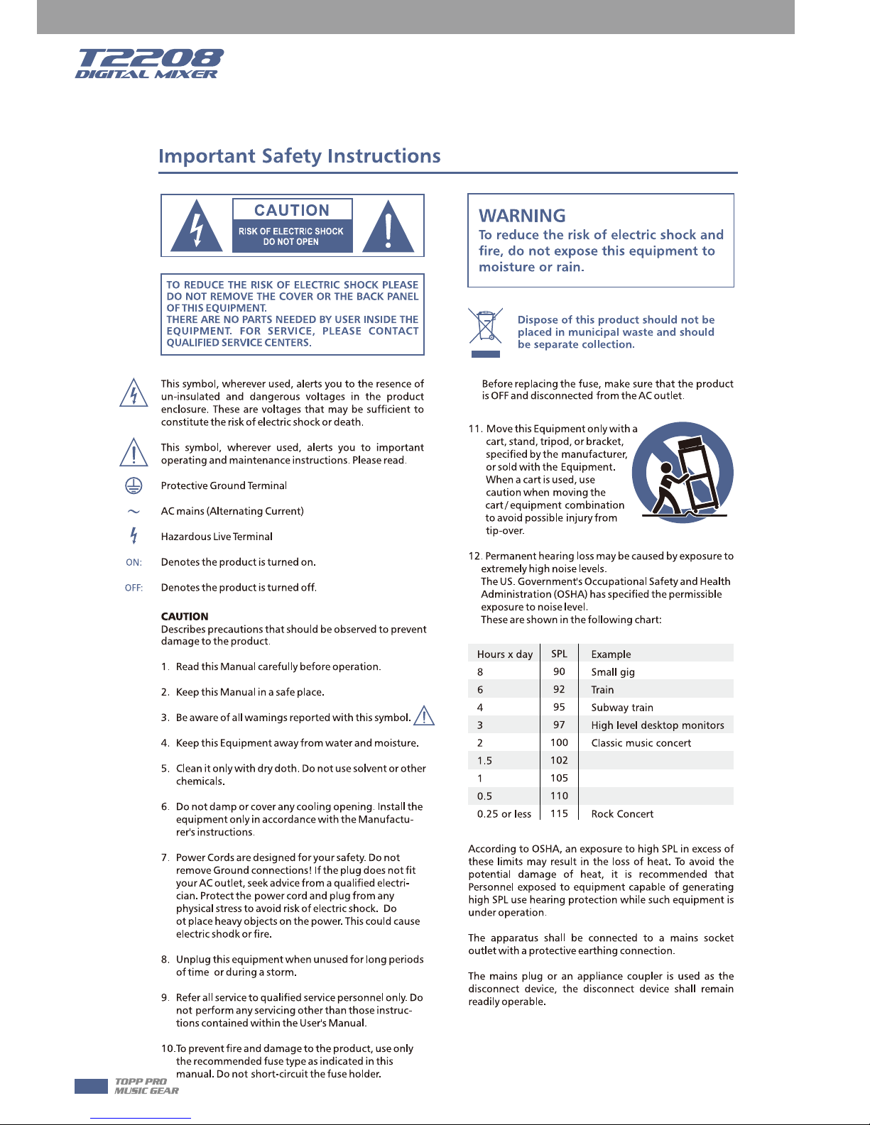
Important Safety Instructions
* T2208, are mixers for professional use. They can be used in following electromagnetic
environment: residential, commercial and light industrial, urban outdoors.
They are the apparatus not intended for rack mounting.
* The peak inrush currents equal to 8.33 A.
*This device complies with part 15 of the FCC Rules. Operation is subject to the following two
conditions: (1)this device may not cause harmful interference, and (2)this device must accept any
interference received, including interference that may cause undesired operation. Changes or
modifications not expressly approved by the party responsible for compliance could void the
user's authority to operate the equipment.
NOTE: This equipment has been tested and found to comply with the limits for a Class B digital
device, pursuant to Part 15 of the FCC Rules. These limits are designed to provide reasonable
protection against harmful interference in a residential installation. This equipment generates,
uses and can radiate radio frequency energy and, if not installed and used in accordance with the
instructions, may cause harmful interference to radio communications. However, there is no
guarantee that interference will not occur in a particular installation. If this equipment does cause
harmful interference to radio or television reception, which can be determined by turning the
equipment off and on, the user is encouraged to try to correct the interference by one or more of
the following measures:
-- Reorient or relocate the receiving antenna.
-- Increase the separation between the equipment and receiver.
-- Connect the equipment into an outlet on a circuit different from that to which the receiver is
connected.
-- Consult the dealer or an experienced radio/TV technician for help.
3
Index
1
2
3
4
5
6
7
8
9
10
11
12
13
14
15
16
19
35
36
37
17
21
22
23 24
28 29 30
31
32
32 33
26 27
25
18
32
34
20
32
Page7: 1. Select button
Page8: 5. Mixer/Long Faders button
Page9: 6. Meters button
Page10: 8. Gate/Comp button
Page11: 10. FX1-2 button
Page12: 12. 48V Phantom button
Page13: 14. DCA button
Page14: 16. Assign to Main button
Page15: 23. Mute button
Page16: 28. FX1/FX2 send
Page17: 35. Control Room knob
Page18: 39. Line inputs 17-20
4. LED meters
9. EQ button
13. System/Routing button
15. DCA1-6 buttons
22. Link button
27. FX1-2 select buttons
34. Parameter Adjust knob
38. Combo Jack
50. Optional module
11.Digital In/Out button
7. Assign/Channel button
38
39
40
41
42
43 44
45
46
47
48
49
50
4
Table of contents
1 Introduction
2 Summary of features
3 Useful data
4 Software Update
5 Control
5.1 Function Buttons and Knobs
7 Hookup Diagram
5.2 Rear Panel
6.1 Mixer interface
6.2 Long Faders interface
6.3 Assign interface
6.4 Channel interface
6.5 Gate interface
6.6 COMP interface
6.7 PEQ interface
6.9 FX1-2 interface
6.10 Digital Input interface
6.1 1 Digital Output interface
6.12 DCA Set interface
6.1 3 Meters interface
6.1 4 Routing interface
6.1 5 System interface
6.1 6 Load interface
6.1 7 Copy interface
6.1 8 Save interface
6.8 GEQ interface
6 DSP Control
6
6
6
7
7
7--17
44
17--18
19
21
22
25
26
28
29
31
32
34
35
35
37
38
39
41
42
43
19
8 Technical information
9 Block Diagram
10 Guarantee
11 Notes
45
46
47
49
5

Introduction
Thank you for purchasing the TOPP PRO T2208 digital mixer. With 20 line-level inputs, 16
microphone preamplifiers and playback engine; processing with 31-band GEQ, compressor, gate,
delay, polarity; DSP effects; aux buses; subgroups; sensitive LED metering; load/save/copy mixer
setting; remote control, USB in and more, the T2208 helps you creating a wonderful show. It is
easy to operate though it has powerful function.
We suggest that you use this manual to familiarize yourself with the features and applications for
your T2208 before using.
- 16 microphone preamplifiers with dedicated trim control
- 20 line-level inputs
- 8 Aux sends
- 2 internal FX
- 1 stereo main out
- All channels Control Room outputs
- 2 headphones output
- USB Stereo recording
- 100mm precision motor fader
- 7 inch color LCD touch screen for graphical view and setup
- 24-bit/48KHz sampling rate
- Program, save, load & copy functions
- Digital noise gate
- Digital compressor/limiter
- Digital 4-band full parametric EQ
- PAN
- Phase reverse
- Time delay
- 6 DCA for Digital Control Audio or MUTE
- Lock and unlock function
- Change the password
- Remote Control: Ethernet or USB
- iPad App T2208 editor for wireless control
- Expand socket for option module: Multi-track USB audio recording module or CobraNet
module or Dante module etc
Summary of Features
Usefull Data
Please write your serial number here for future reference.
6
2
1
3
Software Update
Control
We will always update the T2208 software, please download the latest version from below sites:
www.topppro.com
Since function of T2208 will also change when you update the software, this manual can help
you familiar with the basic function, for the precision, please refer to the real T2208 digital mixer.
Note: When you update the firmware, all the parameters you had saved in the mixer may be
destroyed.
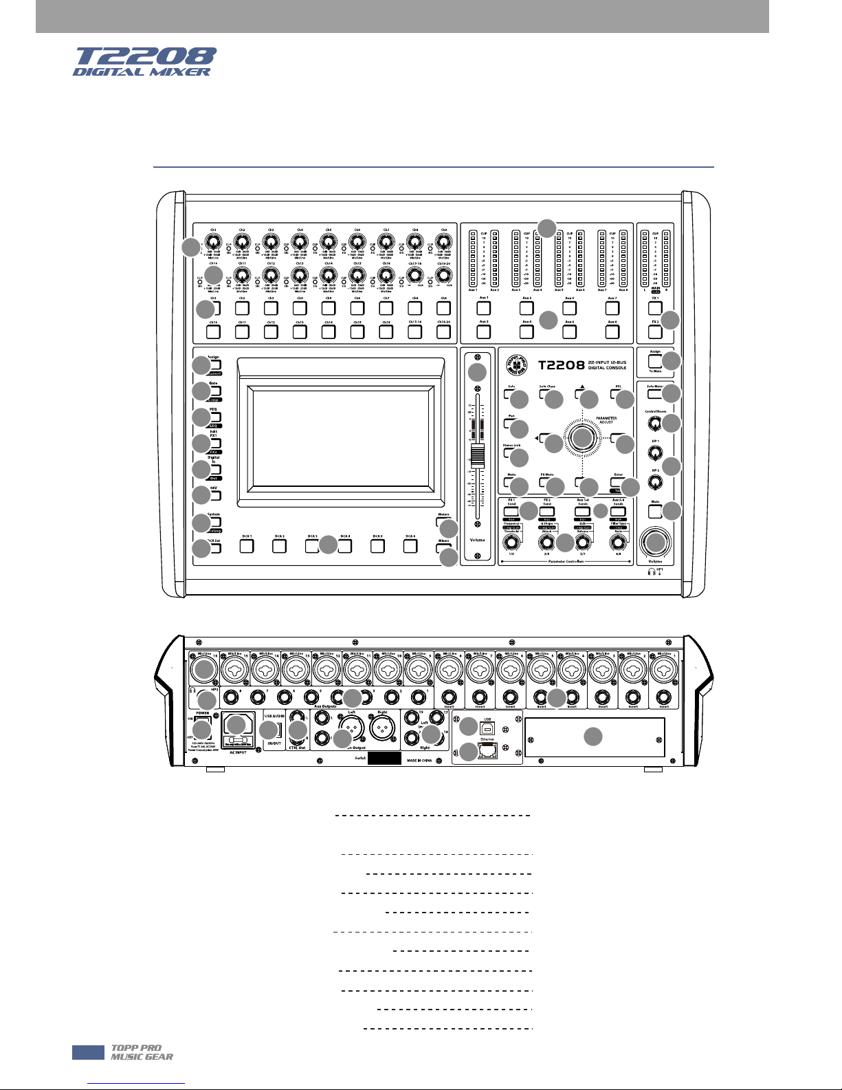
1. Main input channel select buttons
There are 18 select buttons Ch1-20 as you can see on the panel.
Press this button will route its channel to add DSP setting and assign its output. It will illuminate
as has been pressed and enabled. In DCA window, you can select group channels by this button.
2. Main input channel knobs
˙The knob Ch1-16 control the gain level of the channel's input.
Note: It is very important to properly set the level of the input gain to minimize noise and avoid
overload distortion.
˙The knob Ch17-20 control input level of the channels.
3. Main input signal clip indication
These LEDs beside input channel knobs indicate the input level of Channel1-20.
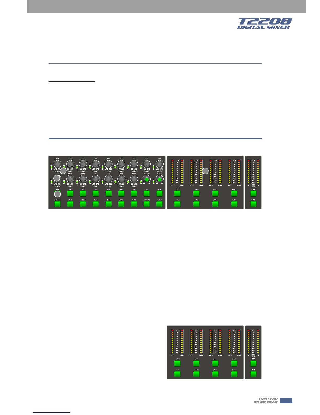
4. LED meters
The LED meters show the signal status, including the output level.
˙AUX1-8 & Main
Indicate the output level of AUX1-8 & Main. Please
be aware only AUX1-8 and Main button engaged
can light the corresponding meters.
˙AUX1-8 button
When the buttons are off, the meters above them
won’t light, while illuminated can light the meters.
˙Main/FX1/FX2/Solo meters
Indicate the input level of Main/FX1/FX2/Solo. Please be aware only FX1/FX2 or Solo meter button
engaged can light the corresponding meters.
5.1 Function buttons and knobs
1
2
4
3
7
4
5
Control
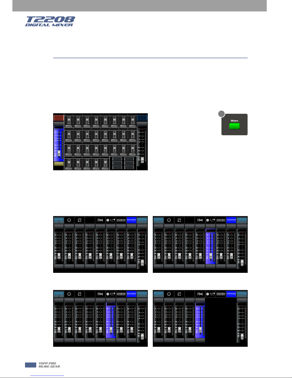
5. Mixer/Long Faders button
Press this button twice, it will switch between Mixer and Long Faders function.
˙Mixer
Press this button, you will see mixer page on LCD screen, where you can control all the input and
output channels’ level, solo and mute, as well as DCA group level control, the window is as
below.
For the detail operation, please refer to the introduction in section 6.
˙Long Faders
Press this button again, you will see Long Faders page on LCD screen, where you can control all
the input and output channels’ level, solo, mute, pan and rename the channel, as below pictures
show.
For the detail operation, please refer to the introduction in section 5.
Name
Main
-10. 5dB
0000000
0
0000
0 0
0000000
0
0
0
-10dB
-10dB
-10dB
-10dB
-10dB
-10dB
-10dB
-10dB
-10dB
-10dB
-10dB
-10dB
000
-10dB -10dB -10dB
000
-10dB -1 0dB -10dB
-10dB
-10dB
-10dB
-10dB
-10dB
-10dB
-10dB
-10dB
-10dB
-10dB
-10dB
DCA
Mute Mute
Name
Main
-10. 5dB
Name
-10. 5dB
CH01
Solo
Long Fader
DCA 1 DCA 2
DCA 3 DCA 4
DCA 5 DCA 6
Ch11Ch10Ch09
Aux5 Aux6
Aux7 Aux8
Aux1
Aux3
Aux4Aux2
FX1 FX2
Ch19-20
Ch12 Ch15Ch14Ch13
Ch02 Ch08Ch07Ch06Ch05Ch04Ch 03
Ch16
Ch01
USBCh17-18
SoloSolo Solo Solo Solo Solo Solo Solo
MuteMut e Mute Mute M ute Mute Mut e Mu te Mu te
Main
Main
-10. 5dB -10.5 dB -10.5d B -10.5dB -10. 5dB-10. 5dB-10. 5dB-10. 5dB
CH01 CH0 2 CH03 CH0 4 CH05 CH 06 CH07
-10. 5dB
CH08
CH01 CH0 2 CH03 CH0 4 CH05 CH 06 CH07 CH 08
Bank Select
Left
Bank Select
Right
Long
Faders
All Faders
DCA
Assign
Channel
Gate
Comp
PEQ
GEQ
FX 1
FX 2
Routing
System
EQ
SoloSolo Solo Solo Solo Solo Solo Solo
MuteMut e Mute Mut e M ute Mute Mute Mut e Mut e
Main
Main
-10. 5dB -10.5 dB -10.5d B -10.5dB -10. 5dB-10. 5dB-10. 5dB-10. 5dB
CH09 CH1 0 CH11 CH1 2 CH13 CH 14 CH15
-10. 5dB
CH16
CH09 CH1 0 CH11 CH1 2 CH13 CH 14 CH15 CH 16
Bank Select
Left
Bank Select
Right
Long
Faders
All Faders
DCA
Assign
Channel
Gate
Comp
PEQ
GEQ
FX 1
FX 2
Routing
System
EQ
SoloSolo Solo Solo Solo
MuteMut e Mute Mut e M ute Mute
Main
Main
-10. 5dB -10.5 dB -10.5d B -10.5dB -10. 5dB-10. 5dB
CH17 -18 CH19 -20 FX1 FX 2 USB
CH17 -18 CH19 -20 FX1 FX 2 USB
Bank Select
Left
Bank Select
Right
Long
Faders
All Faders
DCA
Assign
Channel
Gate
Comp
PEQ
GEQ
FX 1
FX 2
Routing
System
EQ
SoloSolo Solo Solo Solo Solo Solo Solo
MuteMut e Mute Mut e M ute Mute Mute Mut e Mut e
Main
Main
-10. 5dB -10.5 dB -10.5d B -10.5dB -10. 5dB-10. 5dB-10. 5dB-10. 5dB
AUX1 AUX2 AUX3 AUX4 SUB 1 SUB2 SUB3
-10. 5dB
SUB4
AUX1 AUX2 AUX3 AUX4 SUB 1 SUB2 SUB3 SUB4
Bank Select
Left
Bank Select
Right
Long
Faders
All Faders
DCA
Assign
Channel
Gate
Comp
PEQ
GEQ
FX 1
FX 2
Routing
System
EQ
- Page of input channel 1-8 - Page of input channel 9-16
Mixer Page
-Page of output channel AUX1-4/AUX5-8 - Page of input channel17-20/FX1-2/USB
5
8
5
Control
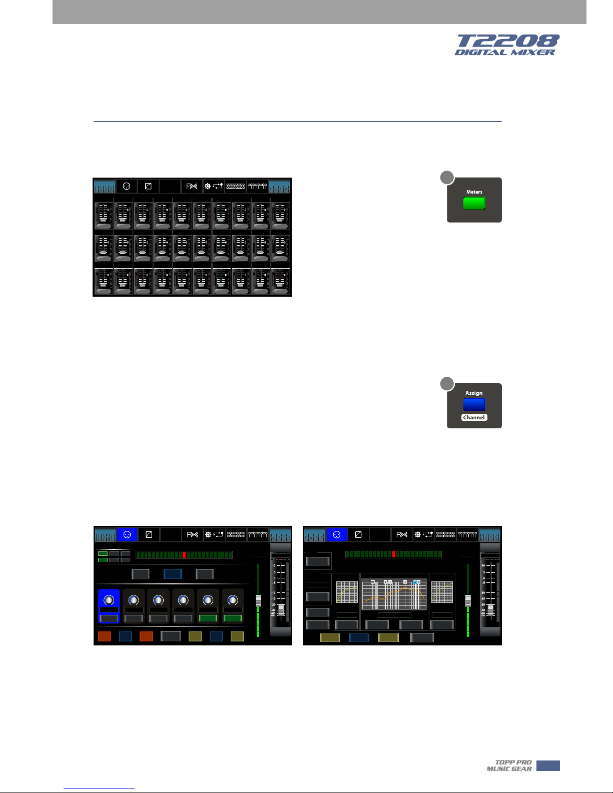
6. Meters button
Press this button to enter meters check page, as below picture show, for the details, please refer
to corresponding introduction in section 6.
7. Assign/Channel button
Press this button twice, it will switch between Assign and Channel function.
˙Assign
Press this button to enter assign page, signal from a selected input channel can
be assigned to Main, AUX1-4, AUX5-8 and FX1-2. The window is as below.
For the detail operation, please refer to introduction in section 6.
˙Channel
Press this button again, you will see Channel page on LCD screen. It gives you a preview of other
function such as Polarity, Delay, Link, Assign, Gate, EQ, Compressor etc.
You can also adjust corresponding parameters that show on the screen. But for Gate here, you
can only adjust threshold; For Compressor, you can only adjust threshold; For EQ, you can adjust
nothing here.
For the detail operation, please refer to introduction in section 6.
Meters Page
Bank Select
Left
Bank Select
Right
Long
Faders
All Faders
DCA
Assign
Channel
Gate
Comp
PEQ
GEQ
FX 1
FX 2
Routing
System
EQ
Sig
Lim
Ch01
OFF
Sig
Lim
Ch02
OFF
Sig
Lim
Ch03
OFF
Sig
Lim
Ch04
OFF
Sig
Lim
Ch05
OFF
Sig
Lim
Ch06
OFF
Sig
Lim
Ch07
OFF
Sig
Lim
Ch08
OFF
Sig
Lim
Ch09
OFF
Sig
Lim
Ch10
OFF
Sig
Lim
Ch11
OFF
Sig
Lim
Ch12
OFF
Sig
Lim
Ch13
OFF
Sig
Lim
Ch14
OFF
Sig
Lim
Ch15
OFF
Sig
Lim
Ch16
OFF
Sig
Lim
AUX1
OFF
Sig
Lim
AUX2
OFF
Sig
Lim
AUX3
OFF
Sig
Lim
AUX4
OFF
Sig
Lim
AUX5
OFF
Sig
Lim
AUX6
OFF
Sig
Lim
AUX7
OFF
Sig
Lim
AUX8
OFF
Sig
Lim
Ch17-18
OFF
Sig
Lim
Ch19-20
OFF
Sig
Lim
FX1
OFF
Sig
Lim
FX2
OFF
Sig
Lim
USB
OFF
Sig
Lim
Main
OFF
Assign Page Channel Page
Solo
Mute
CH08
-10. 5dB
CH08
Assign
FX1
AUX2 AUX4AUX1
FX2
AUX3
-10. 5dB -1 0.5dB -10.5dB -10.5d B -10. 5dB -1 0.5dB
Sends
PRE PRE PRE PRE
Load
Save
DCA Assign
DCA 1 DCA 2 DCA 3
DCA 4 DCA 5 DCA 6
POST PO ST
Select
Channel
Left
Right
Pan
Parameter
Aux 1
-10.5dB
48V
Phase
AUX1-4
Main
AUX5-8
Link
Copy
Channel
Bank Select
Left
Bank Select
Right
Long
Faders
All Faders
DCA
Assign
Channel
Gate
Comp
PEQ
GEQ
FX 1
FX 2
Routing
System
EQ
Solo
Mute
CH08
Parameter
Aux 1
-10.5dB
Delay Time
0.0m S
Polarity
INV.
Delay
Link
Main
Gate
Threshold Threshold
EQ
Compressor
0.0d B 0.0d B
Rock Drums
ON
ON
Flat EQ
ON
Load
Save
Left
Right
Pan
Select
Channel
Copy
Channel
-10. 5dB
CH08
Bank Select
Left
Bank Select
Right
Long
Faders
All Faders
DCA
Assign
Channel
Gate
Comp
PEQ
GEQ
FX 1
FX 2
Routing
System
EQ
6
7
9
5
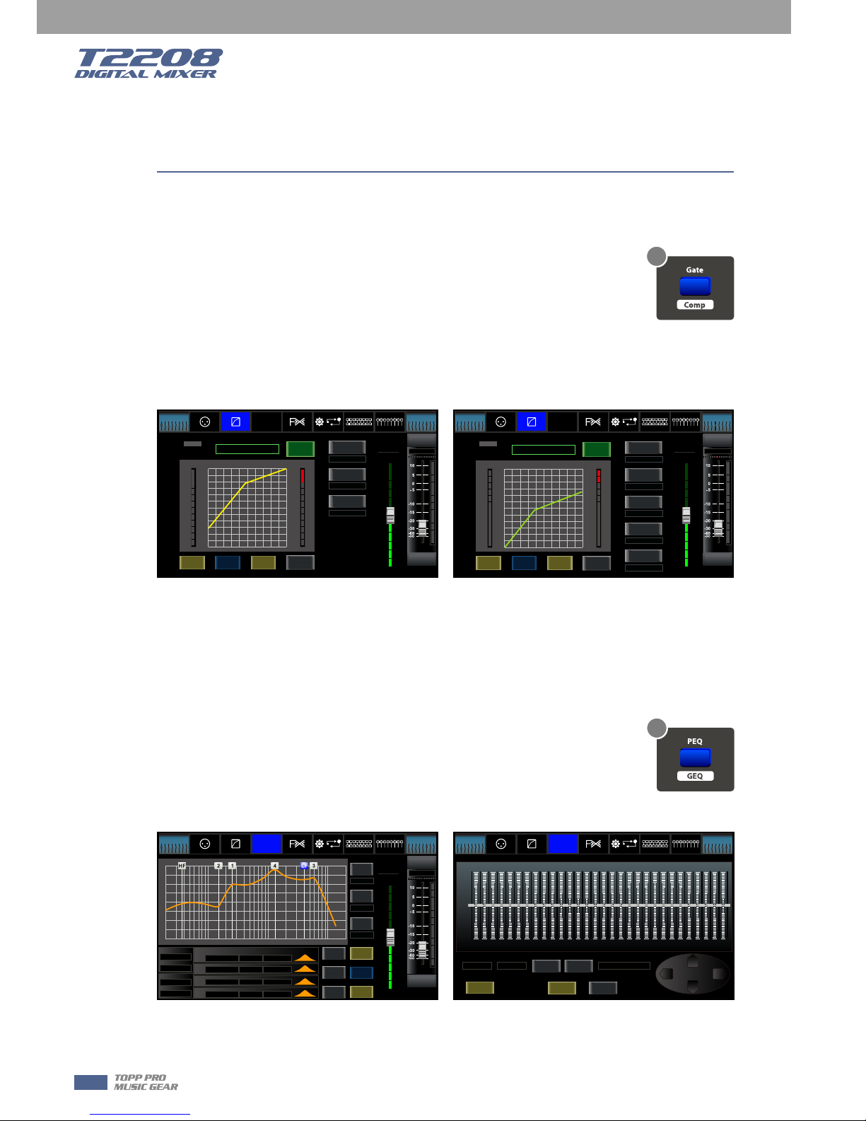
9. EQ button
Press this button twice, it will switch between PEQ and GEQ function.
˙PEQ
An equalizer is a filter that allows you to adjust the level of frequency in the range of 20Hz-20KHz.
The window is as below.
For the detail operation, please refer to introduction in section 6.
˙GEQ
In GEQ page you can set the 31-band EQ. The window is as below.
For the detail operation, please refer to introduction in section 6.
Control
8. Gate/Comp button
Press this button twice, it will switch between Gate and COMP function.
˙Gate
Noise gate attenuates signals that below the threshold and allows signals to pass
through only when they are above a threshold setting. The window is as below.
For the detail operation, please refer to introduction in section 6.
˙COMP
A compressor reduces the level of an audio signal if its amplitude exceeds a certain threshold. The
window is as below.
For the detail operation, please refer to introduction in section 6.
Gate Page Comp Page
Solo
Mute
CH08
Parameter
Aux 1
-10.5dB
1.0KHz
Frequency
3.0
Q
-2.0dB
Gain
Load
Save
OFF
Flat EQ
HPF
LPF
Frequency
Frequency
Type
Type
Q Gain Type
EQ1
Frequency
EQ2
EQ3
EQ4
200H z
200H z
BW24
BW24
200H z
1.0K Hz
5.0K Hz
10.0 KHz
3.0
3.0
3.0
3.0
0.0d B
0.0d B
0.0d B
0.0d B
+24
+18
+12
+6
0 dB
-12
-24
-18
-6
20Hz 50 100 200 500 1K 2K 5K 10K 20K
Select
Channel
Copy
Channel
-10. 5dB
CH08
Bank Select
Left
Bank Select
Right
Long
Faders
All Faders
DCA
Assign
Channel
Gate
Comp
PEQ
GEQ
FX 1
FX 2
Routing
System
EQ
PEQ Page GEQ Page
Load
1 2 3 4 5 6 7 8 9 10 11 12 13 14 15 16 17
0(dB)
-6
-12
-18
-24
18 19 20 21 22 23 24 25 26 27 28 29 3 0 31
20
25 40 63 100 160 250 400 630
31.5 50 80 125 200 315 500 800 1.25K 12.5K2K
20K
3.15K 5K 8K
1K 1.6K 2.5K 4K 6.3K 10K 16K
+24
+18
+12
+6
Up
Down
Left Right
Frequency
Gain
200H z 0.0d B
Save
Defa ult
ON
Flat EQ
Main
Select
Channel
Bank Select
Left
Bank Select
Right
Long
Faders
All Faders
DCA
Assign
Channel
Gate
Comp
PEQ
GEQ
FX 1
FX 2
Routing
System
EQ
8
9
Solo
Mute
CH08
Parameter
Aux 1
-10.5dB
Level LIMIT
(dB)
16
12
7
3
-1
-5
-10
-14
-18
-22
-26
-30
(dB)
4
8
13
17
21
25
30
34
38
42
46
50
CLIP
10
7
4
2
0
-2
-4
-7
-10
-20
-30
Thresh old
Releas e
Attack
50mS
100mS
0.0dB
Save
Load
Gate
ON
Default
Select
Channel
Copy
Channel
-10. 5dB
CH08
Bank Select
Left
Bank Select
Right
Long
Faders
All Faders
DCA
Assign
Channel
Gate
Comp
PEQ
GEQ
FX 1
FX 2
Routing
System
EQ
Solo
Mute
CH08
Parameter
Aux 1
-10.5dB
Level LIMIT
(dB)
16
12
7
3
-1
-5
-10
-14
-18
-22
-26
-30
(dB)
4
8
13
17
21
25
30
34
38
42
46
50
CLIP
10
7
4
2
0
-2
-4
-7
-10
-20
-30
Thresh old
Comp Gai n
Comp Rat io
Releas e
Attack
50mS
100mS
1:1
0.0dB
0.0dB
Save
Load
Comp
ON
Default
Select
Channel
Copy
Channel
-10. 5dB
CH08
Bank Select
Left
Bank Select
Right
Long
Faders
All Faders
DCA
Assign
Channel
Gate
Comp
PEQ
GEQ
FX 1
FX 2
Routing
System
EQ
10
5
Control
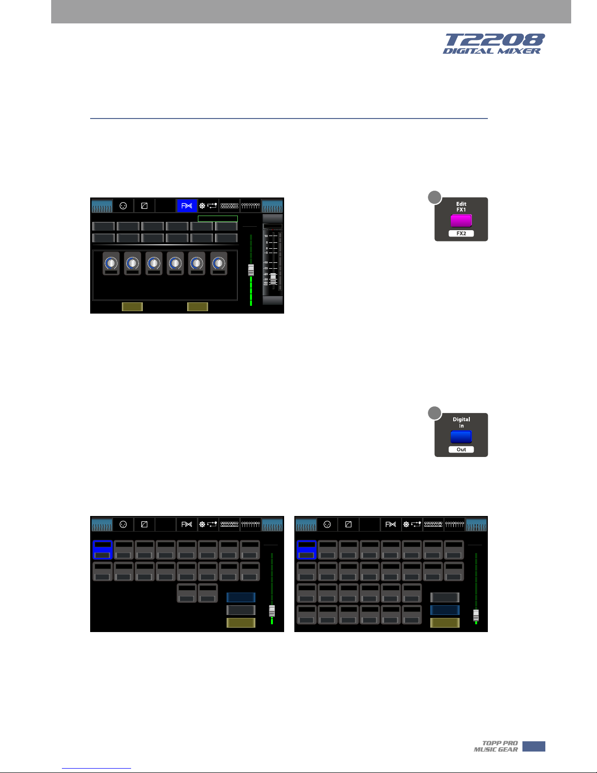
10. FX1-2 button
Press this button twice, it will switch between FX1 and FX2 function.
This page can show and editor the setting of internal effects. Each of the FX owns 12 program
effects. The window is as below.
For the detail operation, please refer to introduction in section 6.
11. Digital In/Out button
Press this button twice, it will switch between Digital In and Digital Out function.
This button engages and disengages the digital channel when you have an optional input/output
module inserted.
˙Digital In
The button will illuminate to indicate that current channel has been selected as
digital input. The window is as below.
For the detail operation, please refer to introduction in section 6.
˙Digital Out
The button will illuminate to indicate that current channel has been selected as digital output.
The window is as below.
For the detail operation, please refer to introduction in section 6.
When the button illuminated, please pay attention to which channel is Digital Input and which
channel is Digital Output during operation.
Solo
Mute
CH08
Parameter
Delay
-10.5dB
Effe ct Type:
Param eters :
Load
Save
Tremolo
ChorusRev
Hall
Flanger
St Delay
Flanger Rev
Room
Chorus
Plate
DelayRev
Delay
StDelayRev
Attack
Decay
Hi Damp
Efx Out
Dry Out Dry O ut
0 0 0 0 0 0
-10. 5dB
CH08
Bank Select
Left
Bank Select
Right
Long
Faders
All Faders
DCA
Assign
Channel
Gate
Comp
PEQ
GEQ
FX 1
FX 2
Routing
System
EQ
FX1-2 Page
Digital In Page Digital Out Page
Parameter
CH01
-25.0dB
CH01
-25.0dB
CH09
0.0dB
AUX1
0.0dB
AUX5
0.0dB 0.0dB 0.0dB0.0dB
CH10
0.0dB
0.0dB
CH16
0.0dB
CH11
0.0dB
CH12
0.0dB
CH13
0.0dB
CH14
0.0dB
CH15
0.0dB
CH02
0.0dB
CH03
0.0dB
CH04
0.0dB
CH05
0.0dB
CH06
0.0dB
CH07
0.0dB
CH08
0.0dB
AUX2
0.0dB 0.0dB
AUX3 AUX4
AUX6 AUX7 AUX8
0.0dB
CH17-18
0.0dB 0.0dB
Main SOLO
0.0dB
CH19-20
Digital Output
Bank Select
Left
Bank Select
Right
Long
Faders
All Faders
DCA
Assign
Channel
Gate
Comp
PEQ
GEQ
FX 1
FX 2
Routing
System
EQ
OFF
OFF
OFF
OFF OFF OFF OFF OFF OFF
OFF OFF OFF OFF OFF
OFF OFF OFF OFF OFF OFF OFF
OFF OFF OFF OFF OFF OFF OFF
Digital Input
Channel Mapping
Parameter
CH01
-20.0dB
CH01
-20.0dB
CH09 CH10 CH16CH11 CH12 CH13 CH14 CH15
CH02
-20.0dB
CH03
-20.0dB
CH04
-20.0dB
CH05
-20.0dB
CH06
-20.0dB
CH07
-20.0dB
CH08
-20.0dB
-20.0dB -20.0dB -20.0dB - 20.0dB -20.0dB - 20.0dB -20.0dB - 20.0dB
-20.0dB
CH17-18
-20.0dB
CH19-20
Bank Select
Left
Bank Select
Right
Long
Faders
All Faders
DCA
Assign
Channel
Gate
Comp
PEQ
GEQ
FX 1
FX 2
Routing
System
EQ
OFF
OFF
OFF OFF
OFF OFF OFF OFF OFF OFF OFF
OFF OFF OFF OFF OFF OFF OFF
Channel Mapping
Digital Output
Digital Input
10
11
11
5
Control
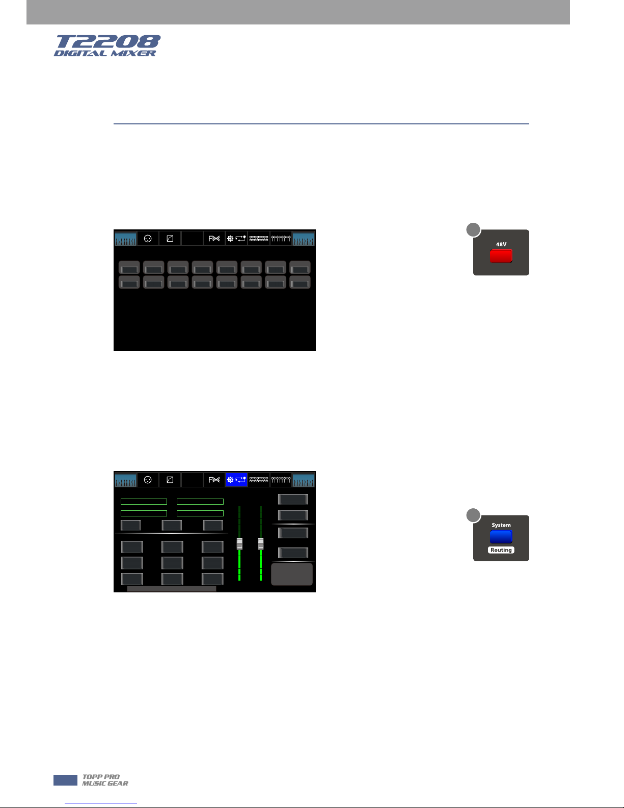
12. 48V Phantom button
Every microphone input equips with an individual phantom power which is controlled by the 48V
phantom power button. When you want to turn on phantom power of some channel, the screen
will show warning to ask you and make sure. It will illuminate when phantom power is activated.
Please notice that only the condenser microphone needs phantom power.
Note: Please do not supply phantom power to any device which do not need phantom power
otherwise the device and T2208 may be damaged.
13. System/Routing button
Press this button twice, it will switch between System and Routing function.
˙System
Press this button to go to System page, as well as show and edit parameters of the system, as
below picture show.
For the detail operation, please refer to the introduction in section 6.
˙Routing
Press this button again, user can select one or several channels in below windows to assign the
signal to corresponding outputs.
For the detail operation, please refer to introduction in section 6.
48V Page
System Page
Bank Select
Left
Bank Select
Right
Long
Faders
All Faders
DCA
Assign
Channel
Gate
Comp
PEQ
GEQ
FX 1
FX 2
Routing
System
EQ
Ch01
DC48V
Ch08Ch02 Ch03 Ch04 C h05 Ch06 Ch07
Ch09 Ch16Ch10 Ch11 Ch1 2 Ch13 Ch 14 Ch15
OFF
OFF
OFF
OFF
OFF
OFF
OFF
OFF
OFF
OFF
OFF
OFF
OFF
OFF
OFF
OFF
Sele cted Ch annel
FX1 FX2
Shor tcut To
Mete rs
Digital
Brightness Adjus t
LCD
Knob
Load
Copy
Save
Default Page Setting
All Faders
Lock
Mixe r
48V
DCA
Routing
GEQ
Password
Setting
Fader
Calibration
Bank Select
Left
Bank Select
Right
Long
Faders
All Faders
DCA
Assign
Channel
Gate
Comp
PEQ
GEQ
FX 1
FX 2
Routing
System
EQ
Default Setting
Lock Matrix
Install Matrix
T1DSP_Firmwa re_1_V1.0
T1DSP_Firmwa re_2_V1.0
T3MCU_Firmwa re_1_V1.0
T0MCU_Firmwa re_2_V1.0
Curr ent Sce ne
Default
Default
Device Name: T2208
Default
Default
12
13
12
5
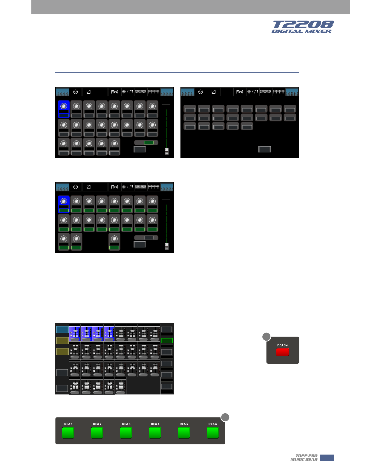
14. DCA button
Digital Control Audio(DCA) can realize group assignment. DCA volume control will always leave
the same ratio between the channel fader levels, independent of the volume control.
Press this button, it will flash until some channels have been selected, then press it again to save
the settings and turn off the button. The corresponding window is as below picture show.
For the detail operation, please refer to introduction in section 5.
15. DCA1-6 buttons
Press these buttons to select which channels you want to be assigned to the group.
DCA Page
Control
- Page of routing input channels to AUX1
(the same with AUX2-8)
- Page of routing input channels to MAIN
- Page of routing input channels to FX1
(the same with FX2)
Main
Select
Bank Select
Left
Bank Select
Right
Long
Faders
All Faders
DCA
Assign
Channel
Gate
Comp
PEQ
GEQ
FX 1
FX 2
Routing
System
EQ
Ch01 Ch08Ch02 Ch 03 Ch04 C h05 Ch06 Ch07
Ch09 Ch16Ch10 Ch11 Ch1 2 Ch13 Ch 14 Ch15
USBCh17-18 Ch19-20 F X1 FX2
OFF OFF OFF OFF OFF OFF OFF OFF
OFF OFF OFF OFF OFF
OFF OFF OFF OFF OFF
OFF OFF OFF
Parameter
CH01
OFF
CH17 -18
CH01 CH08CH02 CH03 C H04 CH 05 CH0 6 CH0 7
CH09 CH16CH10 CH11 C H12 CH 13 CH 14 CH 15
CH19 -20 FX1
PRE P RE
PRE
PRE
FX2
PRE
PRE
PRE
PRE
PRE
USB
PRE
PRE
PRE
PRE
PRE
PRE
PREPRE
PRE
PRE
PRE
All:
AUX1
Select
PRE
Bank Select
Left
Bank Select
Right
Long
Faders
All Faders
DCA
Assign
Channel
Gate
Comp
PEQ
GEQ
FX 1
FX 2
Routing
System
EQ
POST
OFF OFF O FF O FF OF F OFF OFF OFF
OFF OFF O FF O FF OF F
OFF OFF O FF O FF OF F
OFF OFF OFF
Parameter
CH01
OFF
CH17 -18
CH01 CH08CH02 CH03 C H04 CH 05 CH0 6 CH0 7
CH09 CH16CH10 CH11 C H12 CH 13 CH 14 CH 15
CH19 -20
USB
All:
FX1
Select
Bank Select
Left
Bank Select
Right
Long
Faders
All Faders
DCA
Assign
Channel
Gate
Comp
PEQ
GEQ
FX 1
FX 2
Routing
System
EQ
OFF OFF O FF O FF OF F OFF OFF OFF
OFF OFF O FF O FF OF F
OFF OFF OFF
OFF OFF OFF
POST POST POST POST POST P OST POST POST
POST POST POST POST POST P OST POST POST
POST POST POST
PRE
0000
0
000
0
0000000
0
0
-10dB
-10dB
-10dB
-10dB
-10dB
-10dB-10dB -1 0dB -10dB
-10dB
-10dB
-10dB
-10dB
-10dB
-10dB
-10dB
-10dB
Back
To
MIXER
Back
To
Previous
System
Drums
Back Vocals
Aux & Fx
no name
no name
no name
DCA A SSIGN W INDOW
0
-10dB0-10dB0-10dB-10dB
00
0
-10dB
000
-10dB -1 0dB -10dB
0
-10dB
000
-10dB -1 0dB -10dB
Select DCA Group 1 to 6
Highlight/Assign Channels to DCA Group
Click "DCA Set" to Confirm!
DCA2
DCA1
DCA3
DCA4
DCA5
DCA6
DCA Set
DCA Clear
Ch08Ch 07Ch06Ch05
Ch16Ch 15Ch14Ch13Ch12Ch11Ch10C h09
Ch02 Ch0 3 Ch04Ch01
Aux6 Aux7 Aux8Aux1
CH17-18
Aux5Aux3 Aux4Aux2
USBFX1 FX2Ch19-20
14
15
13
5
Control
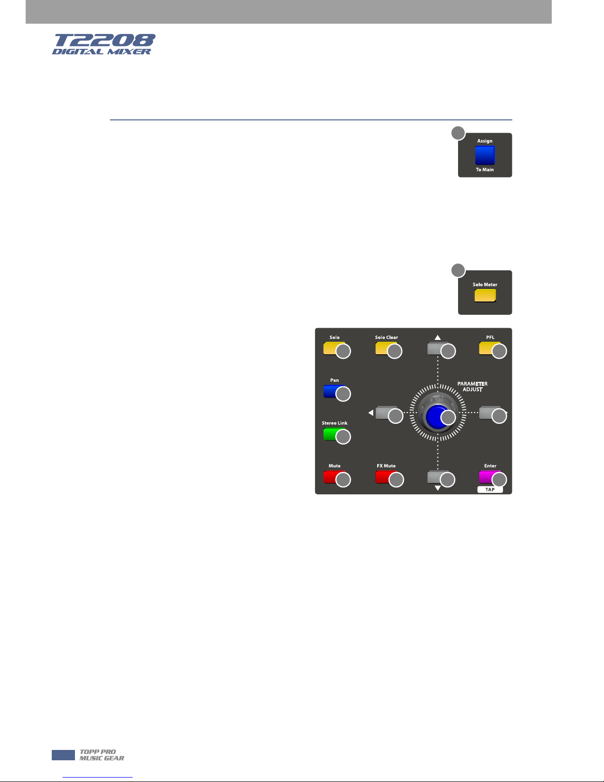
16. Assign to Main button
Press the input channel button, then press this button, can quickly assign the
input channel to main.
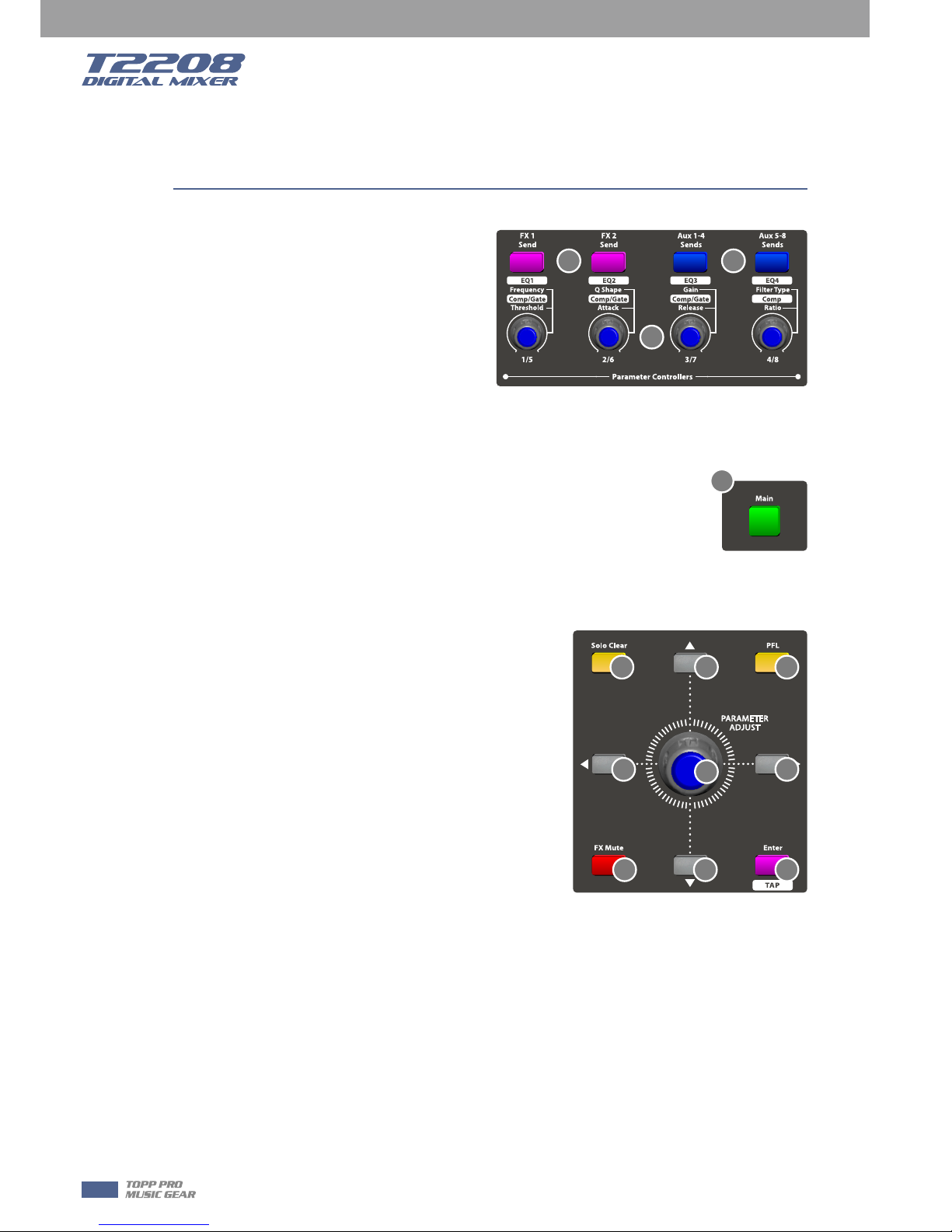
17. Solo button
Press this button will send its channels or buses to the control room outputs. It will illuminate as
has been pressed and enabled.
18. Solo clear button
Press this button to clear the solo function for all of the soloed buses or channels.
19. Solo Meter button
When the button is off, meters above it indicate input level of main, while
illuminated indicate input level of Solo.
20. PFL button
The default setting for the Solo bus is
After-Fader Listen (AFL); by pressing PFL,
Pre-Fader Listening is enabled. In either mode,
press Solo on any channel or bus to route that
channel to the Solo bus and has no effect on
the main.
21. Pan button
Press this button to select the Pan function,
then rotate Parameter Adjust encoder to
control signal level from left to right for the
selected input or output bus. If you have
adjusted a channel pan, please just touch 2
times on the screen and make it back to the
centre position.
The LCD display shows the setting in real time. If two channels have been linked as stereo pair,
the LCD display will automatically change to stereo pan.
22. Link button
Input channels, aux buses, can be linked as a stereo pair. It will illuminate if the stereo link button
has been pressed and enabled. The stereo pairs are predefined and cannot be changed. They are
as follows:
Channels 1 and 2 Channels 13 and 14
Channels 3 and 4 Channels 15 and 16
Channels 5 and 6 Aux 1 and Aux 2
Channels 7 and 8 Aux 3 and Aux 4
Channels 9 and 10 Aux 5 and Aux 6
Channels 11 and 12 Aux 7 and Aux 8
A stereo link can be enabled when either channel in the pair is selected by pressing the Link
button. When the Link button is illuminated which indicates the Stereo Link function enabled, all
DSP setting, solo status and main assignments are passed to the other channel in the pair.
16
19
17 18
21
22
23 24 32
32 32
32
34
20
33
14
5

˙Link & DCA: After link, the channels can also be grouped to DCA as stereo channel, but not able
to cancel the link in DCA. On the contrary, if the channel has been grouped to DCA, it can not link
at all, but its paired channel can link.
For example, channel 5 is linked with channel 6, then both channel 5 and 6 can be grouped to
DCA. But if channel 5 has been grouped to DCA first, it can not link to channel 6, but channel 6
can link to channel 5.
˙Link & Routing: The two linked channels can route as stereo channel, while routed channels can
also link later.
Please note that this is a nondestructive passing, the other channel's previous setting will be
restored after the Link button is disengaged. For example, when Channel 6 has been selected,
then press Stereo Link button, all of Channel 6's setting will be copied onto Channel 5. The
Channel 5's own setting will restore after the Link button has been disengaged.
23. Mute button
Press this button will mute selected channel and all of its assigned
outputs. It will illuminate when the button has been pressed and
enabled.
24. FX Mute button
This button is for FX function, when press it, effects of FX1-2 will be mute synchronously, which
is similar to MUTE button.
25. Motor Fader
There is only one motor fader to control all digital Channel’s level, including 20 main
input channels, 1 USB in, 8 AUX outputs, FX1-2 and 1 Main output channel.
26. AUX1-8 select buttons
This button function is similar to input channel select buttons.
Press this button will route its channel to add DSP setting and assign its output. It will
illuminate as has been pressed and enabled. In DCA window, you can select group
channels by this button.
27. FX1-2 select buttons
This button function is also similar to input channel select buttons and AUX1-4 select
buttons. For the details, please refer to point 22 or 1.
Control
Volume
23 24
25
26 27
15
5
Control
28. FX1/FX2 send
Press the input channel and then press this
button, can assign the channel to use FX1/FX2
effects. And the default level is mute, so you
should tune the knob below the button to take
effects.
29. Aux1-4/Aux5-8 sends
Press the input channel and then press this
button, can assign the channel to use
AUX1-4/5-8. And the default assigned level is mute, so you should tune the knob below the
button to take effects.
30. Main button
The selected channel can be assigned to Main Outputs by pressing the
corresponding button.
The main 20 inputs, USB In, and FX1-2 can be assigned to any or all of the Aux
Sends and the main outputs.
The 8 aux sends cannot be assigned to the main outputs.
31. AUX1-4/5-8 Output Level Control knobs
These knobs here control the output level for AUX1-4/5-8.
32. UP &Left & Down & Right button
These buttons move the cursor around the display page,
or select and delete parameters and options. Sometimes,
Up button function is the same as Left button, while
Down button function is the same as Right button. But in
GEQ, Up and Down adjust gain level, while Left and Right
adjust frequency.
As the function of this button will be a little bit different
in different function, please notice the notes that are
shown on the screen when operating.
33. Enter(TAP) button
This button can activate as two types of function.
˙Enter: Confirm the edited parameter values.
When there is a confirmation message jump out on the screen, press Enter button to answer
“yes”.
˙TAP: In the FX1 and FX2 page, it will switch to TAP function, you can use this button to enter a
delay time in tempo with the music being played.
As the function of this button will be a little bit different in different function, please notice the
notes that are shown on the screen when operating.
34. Parameter Adjust knob
This Encoder adjusts the parameter values of selected control that are shown on the LCD display.
Turning it clockwise increases the value and counterclockwise decreases the value.
As the function of this button will be a little bit different in different function, please notice the
notes that are shown on the screen when operating.
18
24 32
32 32
32
34
20
33
28 29
31
30
16
5
 Loading...