

PUBLIC ADDRESS
AMPLIFIER
User's Manual
MPA SERIES
NF03384-2.0
PA SERIES

TABLE OF CONTENTS
INTRODUCTION
01
CONTROL ELEMENT
02
BACK GROUND MUSIC MODULE DESCRIPTION
04
08
BLOCK DIAGRAM
SPECIFICATION
09
CONNECTION DESCRIPTION
10
PUBLIC ADDRESS AMPLIFIER
11
PUBLIC ADDRESS AMPLIFIER
Cassette recorder
Horn speaker
CD player
AM/FM tuner
GND
Mains
Speaker
CONNECTION DESCRIPTION
110-120V~ 220-240V~
POWERCONSUMPTION: 600W
DC
a24V 20A
-
+
25V
4
COM
110-120V~50/60HzFUSE:T12AL 250V
220-240V~50/60HzFUSE:T6.3AL 250V
Sound column
CLASS 2 WIRING
24V
Battery
10
SAFETY RELATED SYMBOLS
Unplug this apparatus during lightning
storms or when unused for long periods
of time.
External Connection
Microphone stand
The symbol is used to indicate that
some hazardous live terminals are
Microphone
involved within this apparatus, even
under the normal operating conditions.
The symbol is used in the service
documentation to indicate that specific
component shall be only replaced by
the component specified in that
Documentation for safety reasons.
Protective grounding terminal.
Alternating current /voltage.
Hazardous live terminal .
8
Phantom
INPUT2
Line MicLine Mic
Phantom
24V
24V
MUTE
SEN.
INPUT1
HOTCOMGND
++
600
TEL.INPUT
TEL.
LEVELLEVEL
LINEOUT
AUX
CLASS 2 WIRING
COMCOMCOM Z1 Z2 Z3 Z4
SINGLEZONE: 120W(MAX)
SINGLE ZONE: 120W(MAX)
TOTALZONE: 240W(MAX)
TOTALZONE:
INPUT4
240W(MAX)
INPUT3
--
1W
PREOUT
AMPIN
100V70V
Line Mic
Line Mic
Phantom
Phantom
24V
24V
ON: Denotes the apparatus turns on.
OFF: Denotes the apparatus turns off, because of using the single pole switch, be sure
to unplug the AC power to prevent any
electric shock before you proceed your
Speaker Tel.signal
service.
WARNING: Describes precautions that
should be observed to prevent the danger
The external wiring connected to the output
hazardous live terminals requires installation
by an instructed person, or the use of readymade leads or cords.
Do not Remove any Cover
There are maybe some areas with high
voltages inside, to reduce the risk of electric
shock, do not remove any cover if the power
supply is connected.
The cover should be removed by the qualified
personnel only.
No user serviceable parts inside.
Fuse
To prevent a fire, make sure to use fuses
with specified standard (current, voltage,
type). Do not use a different fuse or short
circuit the fuse holder.
Before replacing the fuse, turn OFF the
apparatus and disconnected the power
source.
of injury or death to the user.
Protective Grounding
Disposing of this product should
not be placed in municipal waste
and should be separate collection.
Before turning the product ON, make sure that
it is connected to Ground. This is to prevent the
risk of electric shock. Never cut internal or
external Ground wires. Likewise, never remove
Ground wiring from the Protective Ground
Terminal.
Never cut off the internal or external protective grounding wire or disconnect the
wiring of protective grounding terminal.
The apparatus shall be connected to a mains
socket outlet with a protective earthing
connection.
Equalizer
Power amplifier
CAUTION: Describes precautions that
should be observed to prevent danger of the
apparatus.
WARNING
Power Supply
Ensure the source voltage matches the
voltage of the power supply before turning
ON the apparatus.

PUBLIC ADDRESS AMPLIFIER
Operating Conditions
This apparatus shall not be exposed to
dripping or splashing and that no objects
filled with liquids, such as vases, shall be
placed on this apparatus.
To reduce the risk of fire or electric shock,
do not expose this apparatus to rain or
moisture.
Do not use this apparatus near water.
Install in accordance with the manufacture-r's
instructions. Do not install near any heat
sources such as radiators, heat registers,
stoves, or other apparatus (including amplifiers) that produce heat. Do not block
any ventilation openings.
No naked flame sources, such as lighted
candles, should be placed on the apparatus.
IMPORTANT SAFETY INSTRUCTIONS
Read these instructions.
Follow all instructions.
Keep these instructions.
Heed all warnings.
Only use attachments/accessories spec-
ified by the manufacturer.
Power Cord and Plug
Do not defeat the safety purpose of the
polarized or grounding type plug.
The mains plug is used as the disconnect device,
the disconnect device shall remain readily
operable.
A polarized plug has two blades with
one wider than the other. A grounding
type plug has two blades and a third
grounding prong. The wide blade or the
third prong are provided for your safety.
If the provided plug does not fit into your
outlet, consult an electrician for replacement of the obsolete outlet.
Protect the power cord from being walked on or pinched particularly at plugs,
convenience receptacles, and the point
where they exit from the apparatus.
Cleaning
When the apparatus needs a cleaning, you
can blow off dust from the apparatus with
a blower or clean with rag etc.
Don't use solvents such as benzol, alcohol,
or other fluids with very strong volatility and
flammability for cleaning the apparatus body.
Clean only with dry cloth.
Servicing
Refer all servicing to qualified personnel. To
reduce the risk of electric shock, do not
perform any servicing other than that
contained in the operating instructions unless
you are qualified to do so .
Servicing is required when the apparatus has
been damaged in any way , such as power
supply cord or plug is damaged , liquid has
been spilled or objects have fallen into the
apparatus, the apparatus has been exposed
to rain or moisture , does not operate
normally, or has been dropped.
RMS output
Frequency response
T.H.D.
S/N Ratio
Power consumption
Input/Sensitivity
Output
Zone out
Controls
BGM module
Dimensions(WxDxH)
Weight
TECHNICAL SPECIFICATIONS
AC:120W/ 240W; DC:88W/165W
80Hz-16kHz( 3dB)
1%
MIC: 65dB
Phantom: 65dB
Line: 75dB
AUX: 80dB
110-120V~/220-240V~ 50/60Hz/600W ;DC 24V: 161W/312W
Mic : -52dBV balanced
Phantom : -52dBV / 24V balanced
Line : -10dBV unbalanced
Aux : -6dBV unbalanced
AMP IN : 0dBV unbalanced;
TEL IN : -10dBV balanced
COM , 4 , 25V ,70V , 100V
Z1 Z4 : 100V
4 Input volume controls; 1 Aux volume controls
2 Treble/Bass controls; 1 Master volume control
4 Zone out volume controls;5 Zone out selector switch(units with"S")
3 REC selector switch(models of recording functions)
MP3 PLAYER
MP3 PLAYER+RECORDING
CD-201
MON/TEL
ECHO
420 260 88mm(MPA series)
420 330 88mm(PA series)
10.2kgs(MPA series 120W); 11.0kgs(MPA series 240W)
11.8kgs(PA series 120W); 12.8kgs(PA series 240W)
9

PUBLIC ADDRESS AMPLIFIER
BLOCK DIAGRAM
INTRODUCTION
There are many models of MPA and PA series which have 120W&240W in power. They are
professionally designed for schools, department stores and shopping centres.
More kinds of protection for the new series: such as overload , short-circuits of output
overheat; and you can use it safely and freely. We also design a fan to protect the power
amplifier. The two new series have many acoustic modules, such as MP3 player and recording ,
CD-201, ECHO , telephone paging and monitor for option.
Each input volume can be controlled with the corresponding individual input volume control,
and can be adjusted by means of a master volume and individual bass and treble tone controls.
Emergency operation can be made of DC power source 24V, even when AC power fail. They
have good performance and supply the excellent quality of sound . Besides , users can operate
easily.
Notes: letter"M" means having built-in MP3 player; "R" means having recording function;"S"
means having zone paging, "RS" means MP3 player & recording + zone paging, "2" means
CD-201,And MP3 player has USB interface&SD/ MMC cards or has only USB interface for
customer to choose.
Features:
1. Output: RMS 120W;240W
2. 2 Tones (BASS/TREBLE);5 Input volume controls; 1 MASTER;
3. There are various modules like CD/TURNER/MP3/ECHO/TEL. for option.
4. MP3 player and recording; SD/USB interface
5. MONITOR function; Recording select function;
6. Impedance output is 4 ; constant voltage output is 25V,70V, 100V; output level display
7. 4 MIC (XLR) inputs; MIC/LINE/PHANTOM exchange SW;1 AUX (RCA) INPUT
8. PRE output and AMP input and Line out;
9. 4 ZONE paging with individual volume control and 1 ALL control of zone paging.
Note: The units of ECHO function have three MIC inputs.
8
1

PUBLIC ADDRESS AMPLIFIER
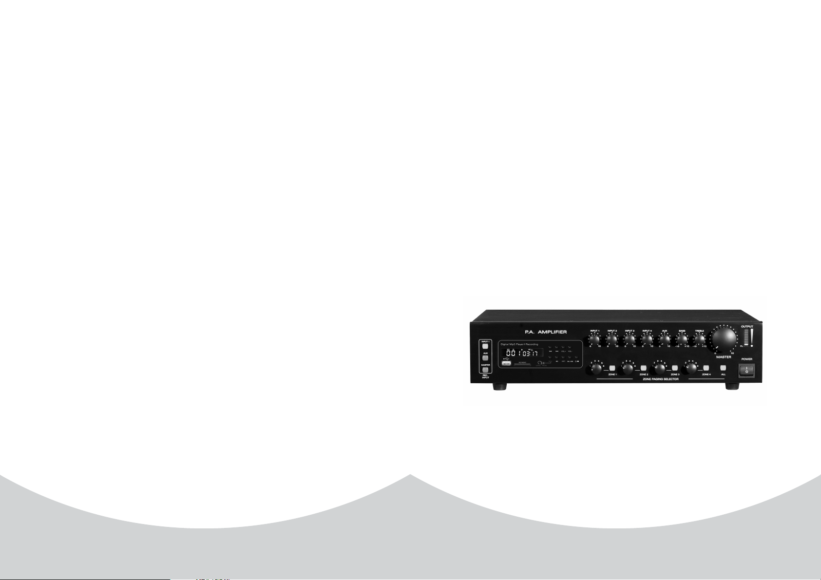
CONTROL ELEMENTS
Take MPA series(120W with MP3 player & recording + zone paging + ECHO) for an
example.
ZONE 3ZONE 3
(2)(3)(6)
OUTPUT
MASTER
ALL
P.L
100
POWER
-10-10 +10+10-10-10 +10+10
TREBLEBASSECHOAUX
ZONE 4ZONE 4
(1)
INPUT 3
INPUT 3
(5) (4) (11)(10)
0 100 100 100 100 10
ZONE PAGING SELECTORZONE PAGING SELECTOR
(9)
1. FRONT PANEL
INPUT 1
INPUT 1
Digital Mp3 Player Recording+Digital Mp3 Player Recording+
MP3 USB
AUX
MASTER
REC.
REC.
INPUT
INPUT
(8)
SD/MMC
P.A. AMPLIFIERP. A . AMPLIFIER
VOL+ VOL-
REC
LEVEL
RPT
PEAK
(7)
INPUT 2INPUT 2INPUT 1INPUT 1
3 3 3 3
4 4 4 4
/
SD/USB
2 2 2 2
5 5 5 5
6 6 6 6
1 1 1 1
ZONE 1ZONE 1 ZONE 2ZONE 2
(1) POWER SWITCH
Themainpowercanbeswitchedonoroffwithit.
(2) TREBLE
Use the knob to control the high frequency at the range of 10dB.Turn clockwise to boost
and counterclockwise to attenuate the treble response. Tone is flat at centre.
(3) BASS
Use the knob to control the low frequency at the range of 10dB.Turn clockwise to boost
and counterclockwise to attenuate the treble response. Tone is flat at centre.
(4) MASTER
This knob is used to adjust the overall gain of the unit.
(5)AUXVOLknob
The knobs are used to adjust the gain of AUX. Adjust clockwise to increase the volume while
adjust counterclockwise to decrease the volume .
(6) INPUT 1-3 VOL Knobs
The knobs are used to adjust the gain of input1-3 respectively. Adjust clockwise to increase the
volume while adjust counter-clockwise to decrease the volume.
1) Switch on the equipment and start the player by pressing the (E) key.
2) The player will activate and the display will light up, indicating whether there is already a
compact disc in the drive or not.
3) Press the key again to close the drive. The display will show the total number of tracks.
4) The first track starts to play out automatically.
If this does not happen, press(I).
*.mp3 files
As already described for audio CDs, the *.mp3 files will start to play automatically one the CD
has been inserted into the CD drive or after inserting a USB key in the socket provided for it
(M). With the drive at a standstill, the display will show the number of folders present on the
disk and the total number of tracks.
To switch from the CD mode to the USB mode and vice versa, press (H).
NOTE:
To stop playing, press(N) once. If you press (D) the disk will be ejected, whether the
player if off or is playing.
Description of the functions
A) REPEAT and RANDOM functions
These functions allow one or more tracks to repeated as required or random selection of the
tracktobeplayed.
To switch from one mode to another simply press (G).
Three symbols are associated with this mode:
.REP
To repeat the track selected.
.ALL
To repeat all the tracks.
.RAN
To play out the tracks in
random order.
B) Normal playing
This is the standard operating mode,
that is to say, playing the tracks in the
pre-defined order. Press (I) to start
playing track 1.
(7) MP3 MODULE
Regarding its function and operation, please see the BGM module description in detail.
Note: MP3 player, recording, CD-201 are assembled to different units of the series.
(8) REC SELECTOR
In the status of recording, press INPUT1 to record the sound source of INPUT1, press AUX to
record sound source of AUX, press MASTER to control all inputs. Only units with recording
function have these control keys.
(9) ZONE PAGING SELECTOR
2
7

PUBLIC ADDRESS AMPLIFIER
3.CD-201
USING THE CD/MP3 PLAYER
DESCRIPTION OF THE CONTROLS
Key for switching on player.
This key enables the CD drive to be opened/closed.If it is pressed with
the player at a standstill or while it is playing,the disc will be ejected from
the drive.
Volume adjustment.
Next track.
Last track.
Pressed one with the player at a standstill or paused, the disc will be
played or resumed. Pressed once with the player running, it will pause
the playing untill the key is pressed agin.
By pressing this key, you will be able to repeat the track that has just been
selected, the whole sequence or random order.
By pressing this key, the disc playing will be stopped.
By pressing this key, you will be able to switch from
the CD mode to the USB mode and vice versa.
There are four zone paging controls and one mains zone paging control. Press ZONE1-4 keys,
the output terminals in front panel have respective output. And rotate the four knobs to control
the volume by adjusting clockwise to boost the volume and adjusting counterclockwise to
attenuate the volume. W he four zone paging controls work
hen the "all" key is switched on , t
simultaneously and the volume is at the maximum value .
(10) ECHO FUNCTION
(11) Output level indicator and power LED.
It is used to control ECHO.
2. REAR PANEL
(21) (24) (25) (26) (28)
110-120V~ 220-240V~
POWERCONSUMPTION: 600W
GND
110-120V~50/60HzFUSE:T12AL 250V
220-240V~50/60HzFUSE:T6.3AL 250V
(14)(13)(12)
(12) FAN
It is used to blow off heat and cool when
the temperature rises during operation.
(13) GND
It is ground connection.
(14) AC JACK
This connector is meant for connection
of the supplied main cord. Do not insert
the power cord into this unit until
voltage has been correctly set.
(15) DC INPUT
It is used for DC power supply for 24V.
You should pay attention to the polarity.
(16) OUTPUT TERMINALS
Connections for low impedance 4
speakers; connections for constant
voltage 25V,70V or 100V speakers.
(17) AMP INPUT/PRE OUT
Jacks AMP IN and PRE OUT to insert
an audio unit for signal processing.
ZONE OUTPUT TERMINALS(18)
There are 4 zone output terminals
which are controlled by key (9).
(19) MUSIC ON HOLD VOL
It is used to monitor volume of black
ground music and AUX.
LINEOUT
AUX
CLASS 2 WIRING
COMCOMCOM Z1 Z2 Z3 Z4
SINGLEZONE: 120W(MAX)
SINGLE ZONE: 120W(MAX)
TOTALZONE: 240W(MAX)
TOTALZONE:
INPUT4
240W(MAX)
PREOUT
DC
a24V 20A
-
+
4
COM
CLASS 2 WIRING
AMPIN
100V70V
25V
Line Mic
Phantom
24V
(15) (16) (17) (18) (19) (20) (22) (23)
(20) MUSIC ON HOLD OUTPUT
It is connected to monitor the signal
of AUX input.
(21) POWER SELECT SWITCH
There are two voltages to choose:
110-120V~ and 220-230V~.
TELEPHONE PAGING(22)
It is connected with telephone.
TELEPHONE LEVEL(23)
It controls the level of telephone input.
(24) LINE OUT
It is connected to recorder and pass on
mixed signal.
(25) AUX IN
It is used for AUX input.
(26) INPUT1-4
They are used for both balanced and
unbalanced inputs.
(27) MIC/PHANTOM/LINE SELECT SWITCH
It is turned to left for MIC, middle for
PHANTOM, and right for LINE.
(28) MUTE/SEN
With MIC 1or TEL paging working, all
other input signals are muted.
Line Mic
Phantom
24V
INPUT3
(27)
--
8
1W
Phantom
INPUT2
Line MicLine Mic
Phantom
24V
++
TEL.INPUT
600
INPUT1
24V
MUTE
SEN.
HOTCOMGND
TEL.
LEVELLEVEL
6
3

PUBLIC ADDRESS AMPLIFIER
BACK GROUND MUSIC MODULE DESCRIPTION
1.MP3 PLAYER+RECORDING
Digital MP3 Player Recording+Digital MP3 Player Recording+
MP3 USB
SD/MMC
a
SD/MMC
b
c
DISPLAY
LEVEL
d
e
REC
f
g
RPT
SD/USB
h
i
j
k
/
VOL-
VOL+
l
m
USB interface
SD/MMC hole
Display operation status of MP3.
Control the volume of recording.
After power on, press REC and prepare to record. Then select the
save way with the USB/SD button .Press REC again. If "REC" lights
about 3~4 times, record begins. During record, do not do other
operations until press "STOP" to stop. If "Err" appears, press
"STOP" to stop recording
IfthemodelisconnectedtoUSBorSDclip,itcanmakeaselective
play automatically after powered on. And it plays the USB
equipment prior. When the model is in waiting status, it plays
automatically after inserting USB save equipment or SD clip. When
it is in a stop or pause, begin to play after pressing PLAY/PAUSE.
After press REP, you can select the below four repeat mode:
Play in order: no picture displays; Repeat single: REP 1;
Repeat all: REP ALL; Random play: REP.
Select save device with the key USB/SD.
Hold POWER button for 3 seconds.When the display of mold lights,
it means that the model is powered on. Hold the button for 3 seconds
again. When the display of model goes out, it means it is powered
off. Start to search playable equipments after powering on.
Press VOL- to decrease the volume and press VOL+ to
increase the volume. Factory default :10.
In the status of play or pause, the model plays next song or previous
one when press or , and the status has no change. It plays
the next file or previous file when hold or for about 2
seconds, and the status is as before. When the current file is
recording one, "FrE" appears in the display.
LEVEL
PEAK
REC
VOL+ VOL -
SD/USB
RPT
2.MP3 PLAYER(with USB, SD/MMC cards)
g
i
VOL+ RPT SD USBSD USB
c
/
SD/MMC
e
a
USB CONNECTOR
b
SD/MMC CARD
CONNECTOR
c
d
e
f
g
h
i
j
k
a
DISPLAY
VOL-
VOL+
RPT
/
SD/USB
b
Insert USB player
Insert SD/MMC Card
Display the status of USB playing
Play the next title
Play the last title
Press this key to decrease the sound level.
Press this key to increase the sound level.
Press this key to start to play
Press this key to repeat the title
Press this key to switch the power or stop the title
Press this key to select the SD Card or USB Player
VOL- /
d
f
/
k
j
h
4
5
 Loading...