

Page 1
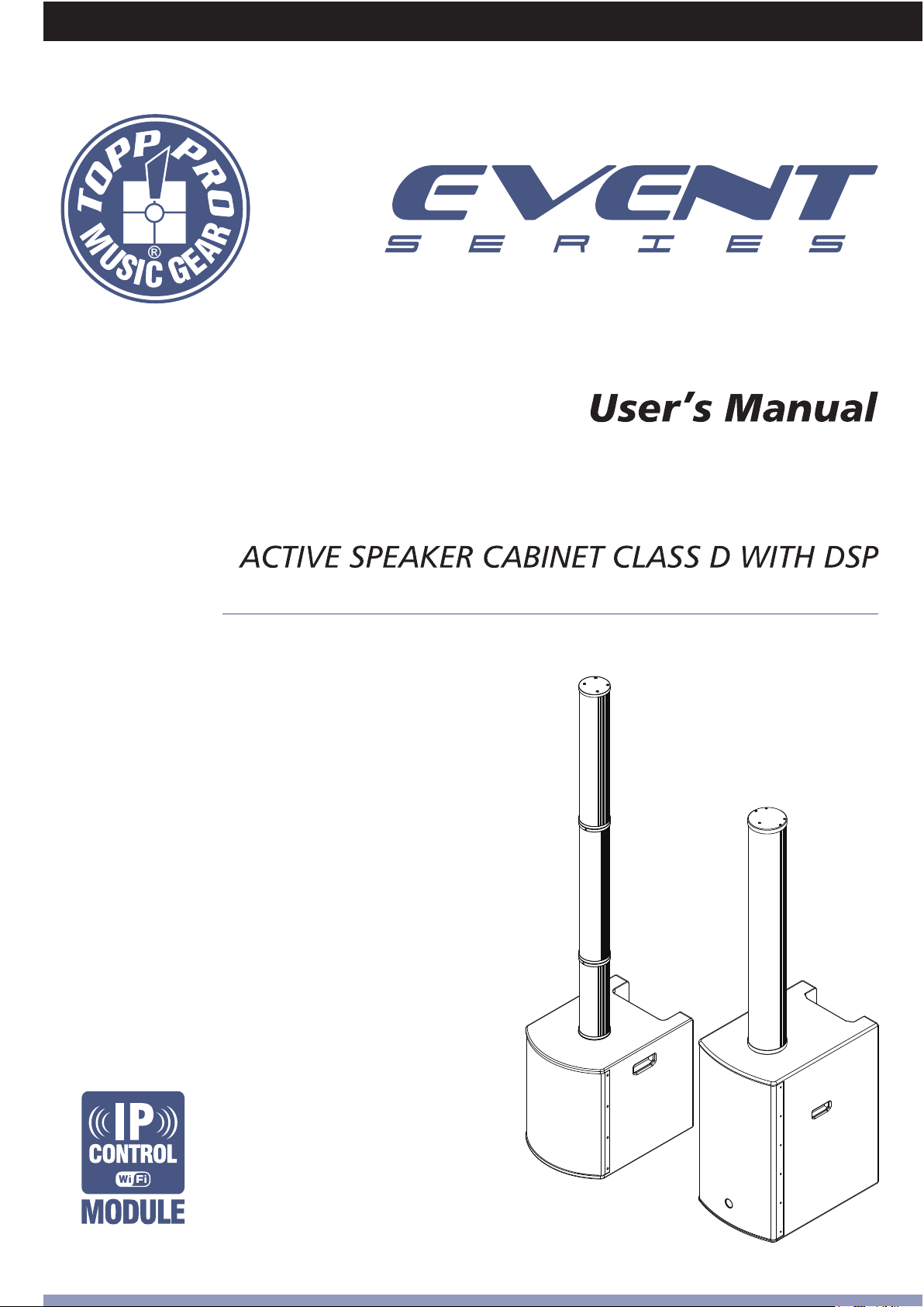
EVENT 2K SYSTEM / EVENT 4K SYSTEM
Page 2
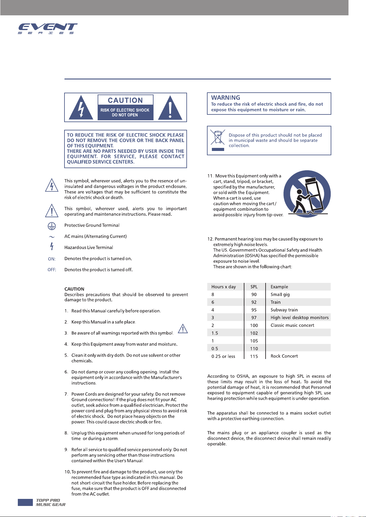
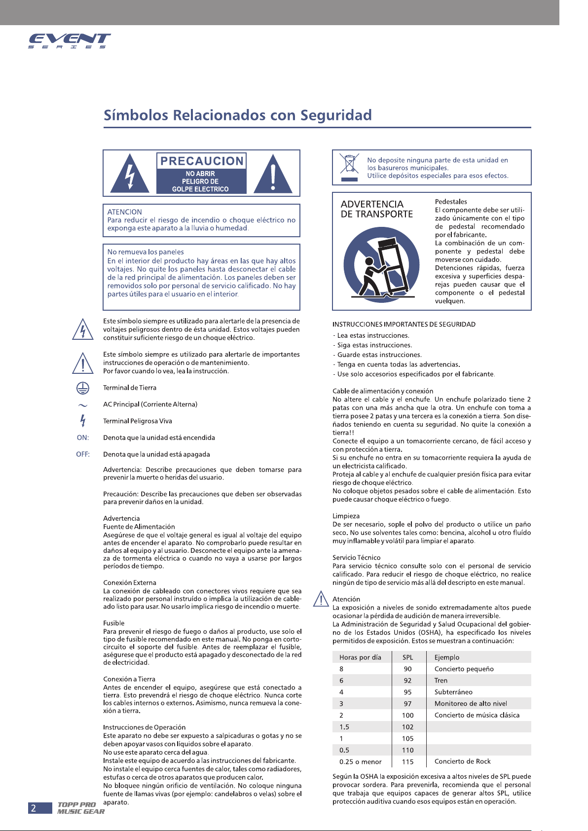
Important Safety Instructions
2
Page 3
Table of Contents
1. INTRODUCTION
2. INSTALLATION TIPS
3. USEFULL DATA
4. QUICK START
5. CONNECT MANNER
6. BACK PANEL DESCRIPTION
7. DSP CONTROL
7. CONNECTION PLATE SYSTEM
8. WIRE CONNECTIONS
9. TECHNICAL SPECIFICATIONS
10. DSP SOFTWARE CONNECTION / IP CONTROL INSTRUCTION
10. GUARANTEE
4
4
4
5
6
8
9
13
15
16
18
19
3
Page 4
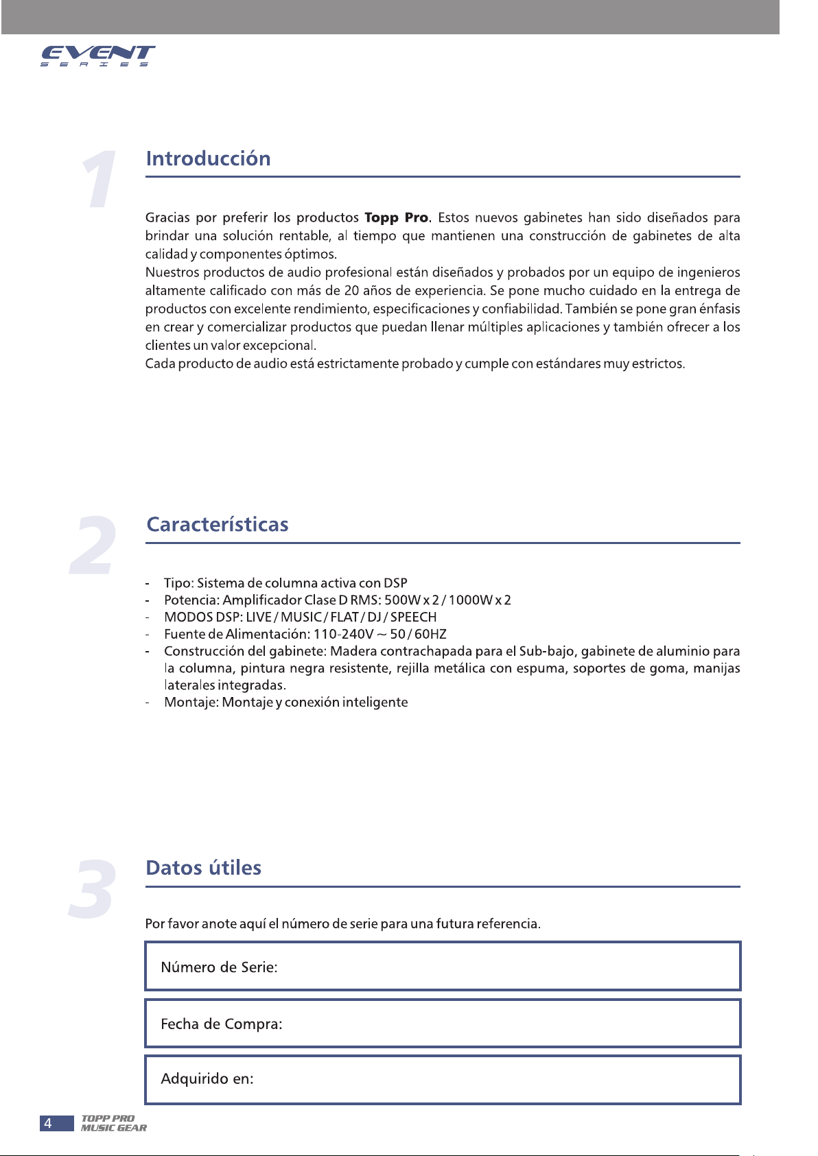
Introduction
1
2
The new cabinets have been designed to provide a cost effective high grade solution while maintainig high
quality cabinet construction and optimum components.
Our Professional Audio Products are designed and tested by a highly qualified engineering team with more
than 20 years of experience. Great care is placed in delivering products with excellent performance,
specifications and dependable reliability. Also great emphasis is placed in creating and bringing to market
products that can fill multiple applications and also offer customers exceptional value.
Every audio product is strictly tested and complied to very strict standards.
Features
- System Type: Active column system with DSP / controls
- Power Rating: Class D RMS:500W*2 / 1000W*2
- DSP MODES: LIVE / MUSIC / FLAT / DJ / SPEECH
- Power Supply: 110-240V ~50/60HZ
- Enclosure Construction: Plywood Cabinet for SUB, Aluminium Cabinet forolumn, Resistant black paint,
metal grille with foam, Rubber feet, integrated side handles
- Mounting: Smart Mounting and Connection
3
4
Page 5
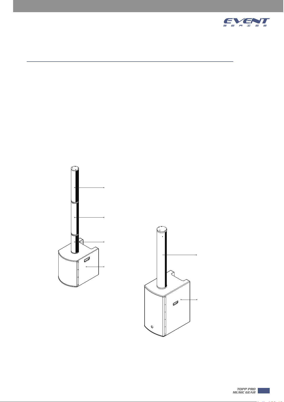
Quick Start
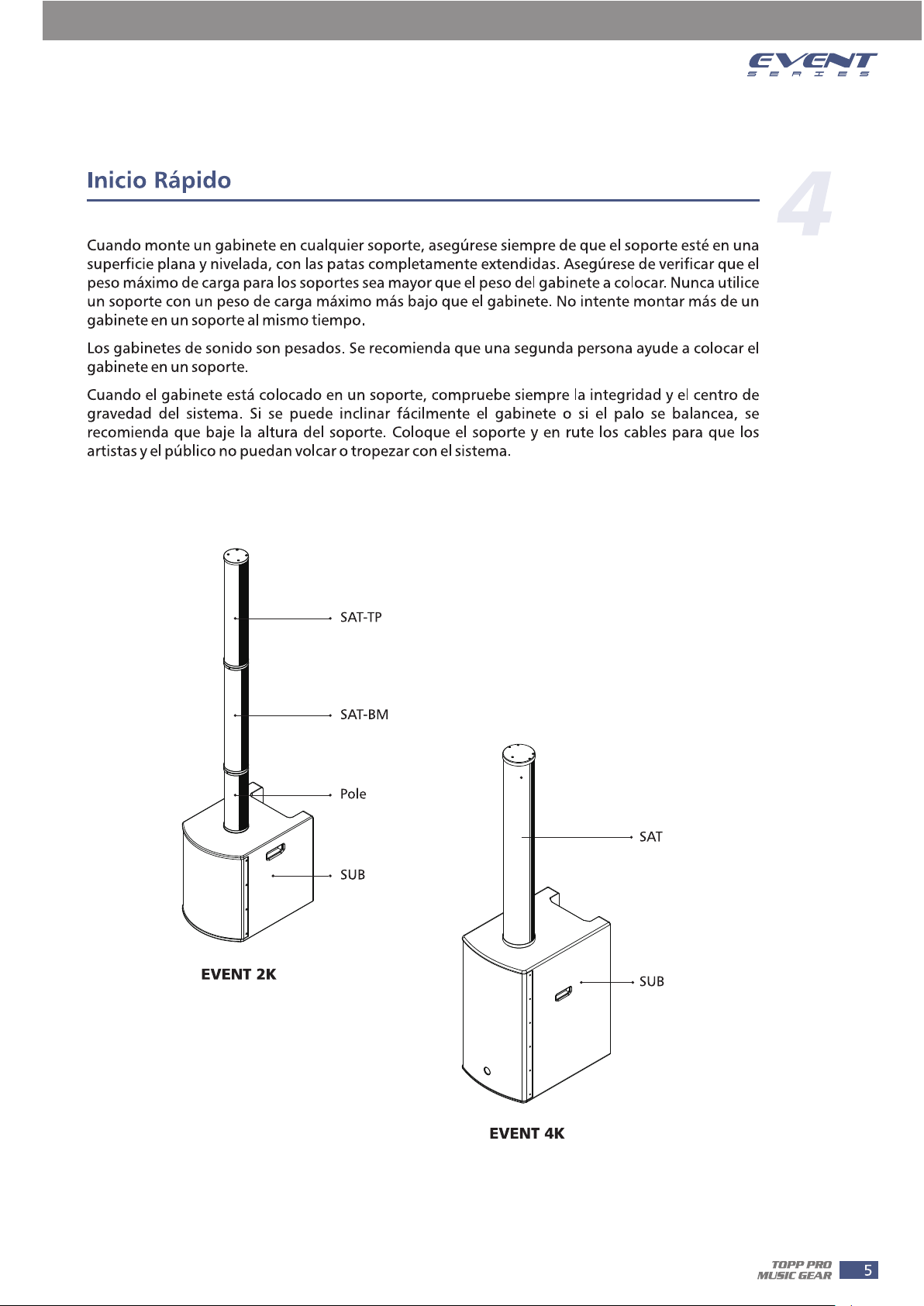
When mounting a speaker onto any stand, always ensure that the stand is on a flat, level sur-face, with the
legs fully extended. Be sure to check that the maximum load weight for the stands is greater than the weight
of the ARRAY SYSTEMS loudspeaker. Never use a stand with a maximum load weight lower than the speaker.
Do not attempt to mout more than one speaker on a stand at one time.
The ARRAY SYSTEMS loudspeakers are heavy. It is recommended that a second person to help place the
cabinet on a stand.
When the speaker is placed on a stand, always check the integrity and center of gravity of the system If the
speaker can be tipped easily, or the pole is swaying, it is recommended that you lower the height of the
stand. Position the stand and route cables so that the performers and the audience cannot tip over or trip
on the system.
SAT-TP
4
EVENT 2K
SAT-BM
Pole
SAT
SUB
SUB
EVENT 4K
5
Page 6
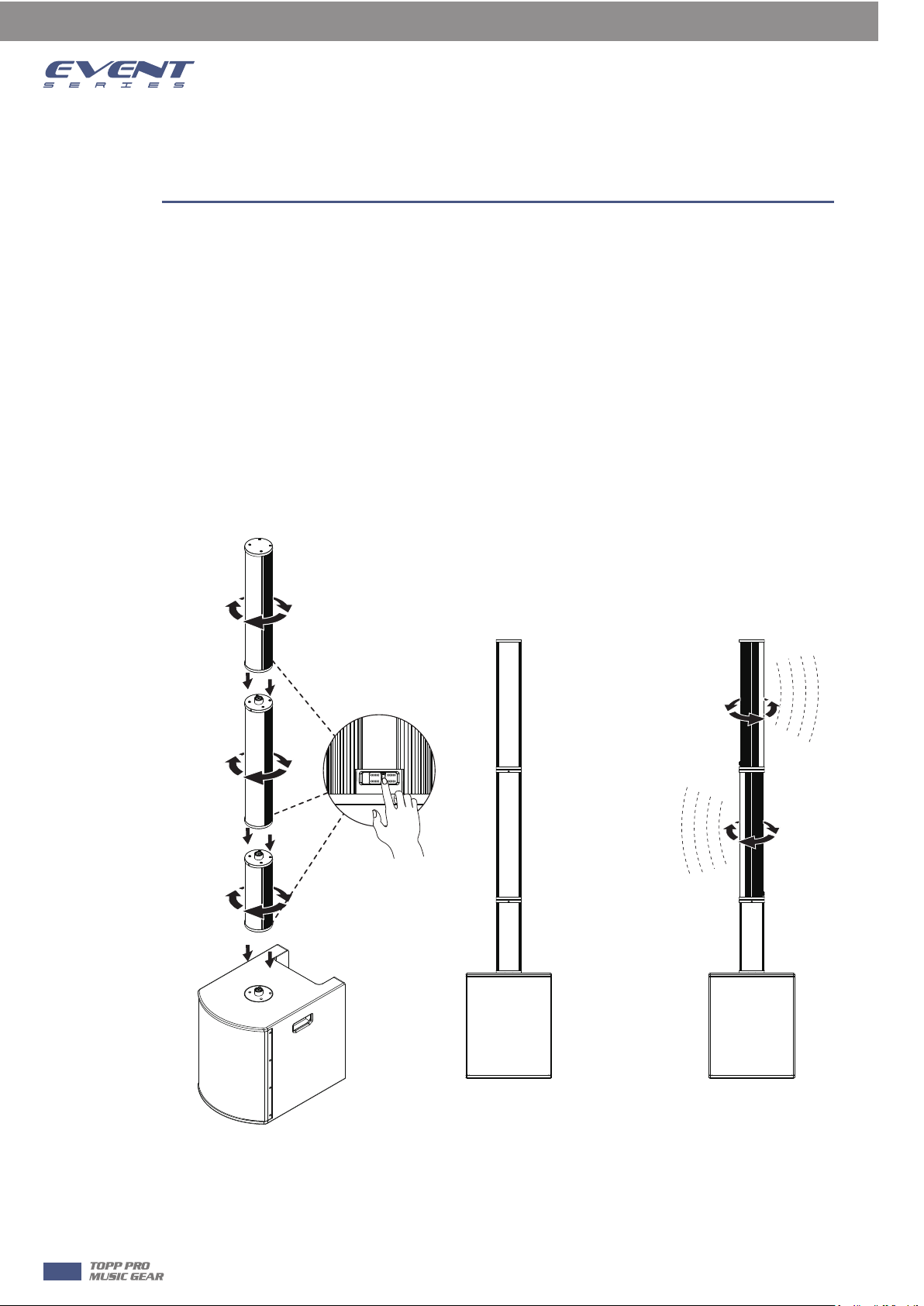
Connect Manner
UNLOCKLOCK
5
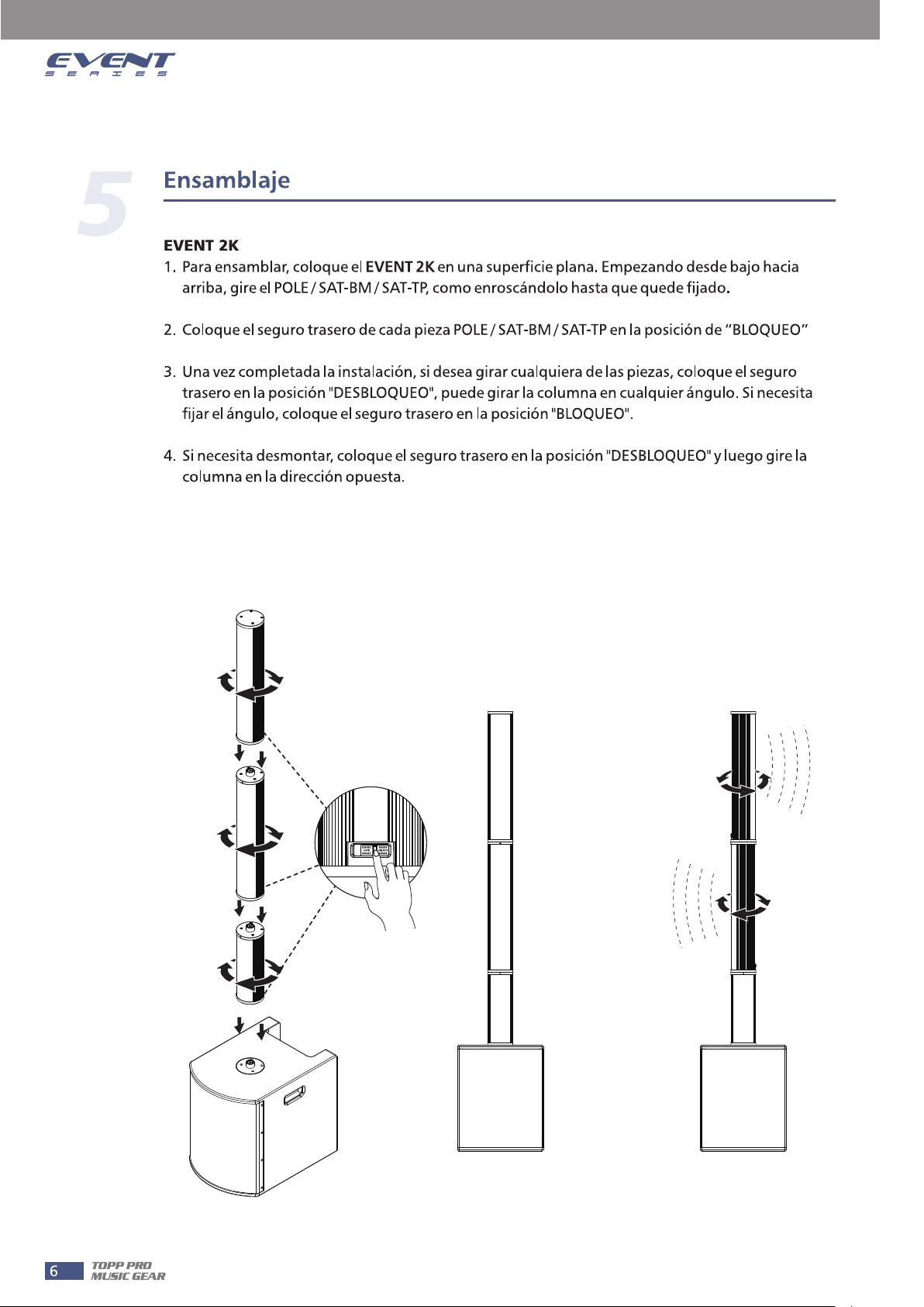
EVENT 2K
1. Turn the POLE/SAT-BM/SAT-TP back control switch to “LOCK” position.
2. Place the EVENT 2K on a flat surface and rotate the POLE/SAT-BM/SAT-TP from low to high into the bottom
threaded bracket until it is tight.
3. After the installation is completed, if you choose to turn the control switch to the “UNLOCK” position, you
can rotate the column to any angle. If you need to fix the angle, turn the control switch to the “LOCK”
position.
4. If you need to disassemble, turn the control switch to the “LOCK” position, and then rotate the column in
the opposite direction.
6
Page 7
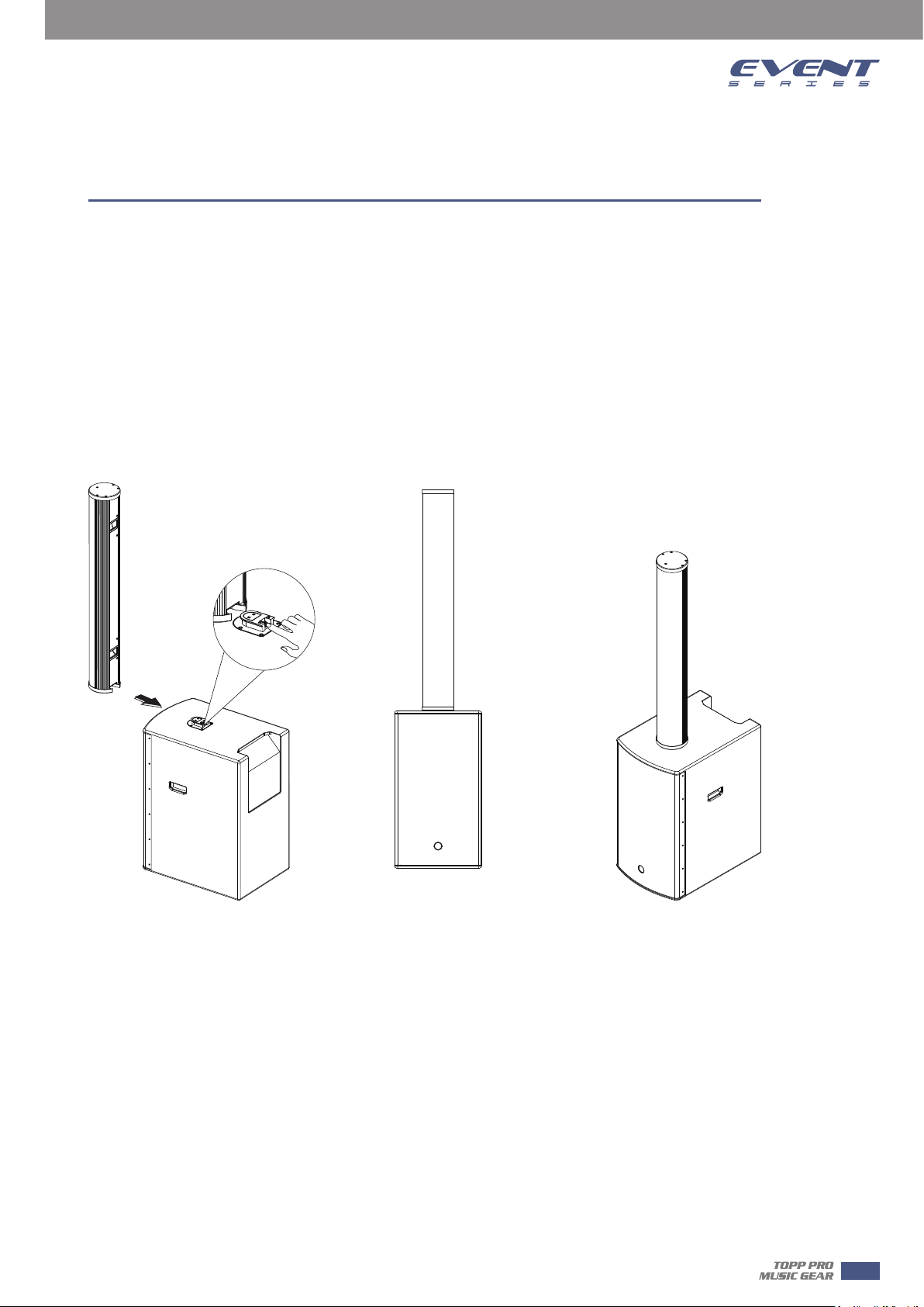
Connect Manner
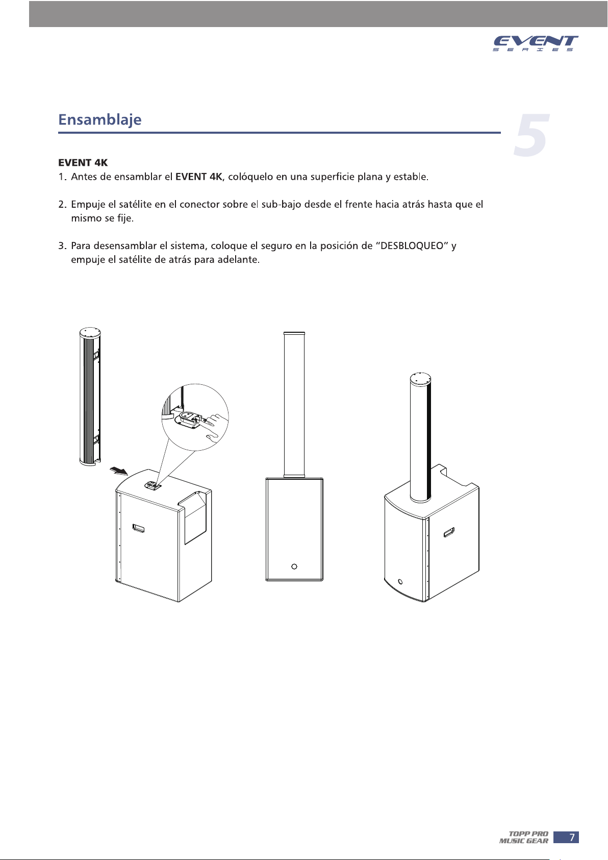
EVENT 4K
1. Place the EVENT 4K SUB on a flat surface.
2. Push the SAT from front to back into the SUB connector until it is tight.
3. After the installation is completed, if you need to disassemble, press the “LOCK” button of the SUB
connector and push the SAT forward slowly.
5
7
Page 8
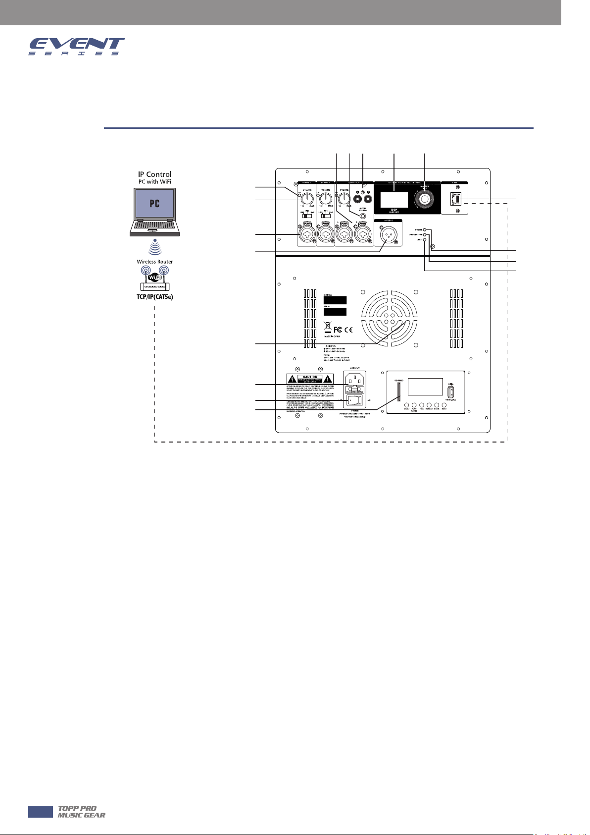
Back Panel Description
6
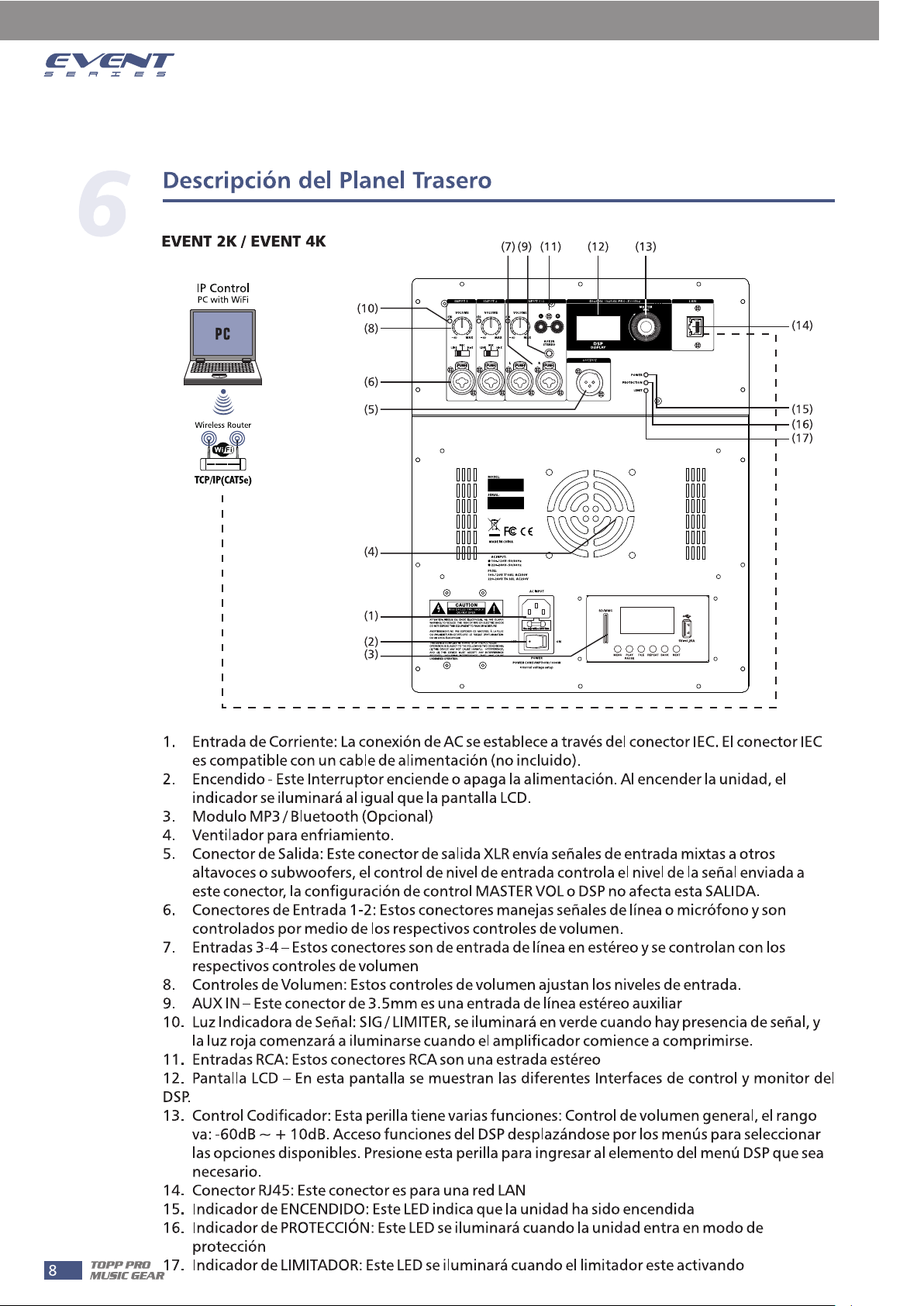
EVENT 2K / EVENT 4K
(10)
(8)
(6)
(5)
(4)
(1)
(2)
(3)
(9)
(7) (11) (12) (13)
(14)
(15)
(16)
(17)
1. AC INPUT-The AC connection is established via the IEC connector. The IEC connector is compatible with
a lockout power cord (not included).
2. POWER - AC switch for turning the power on or off. When POWER is turned on,the power led lights up
and LCD screen lights up.
3. MP3/BT PLAYER for option.
4. Convection fan.
5. OUTPUT - The XLR output sends mixed input signals to other speakers or subwoof
the level of signal sent to the OUTPUT, The MASTER VOL or DSP control settings do not affect the
OUTPUT.
6. INPUT1 / INPUT2 - FOR line\ MIC or HI-Z input level control is available for INPUT 1/2
7. INPUT3/4 - FOR line stereo input level control is available for INPUT 3/4
8. RCA INPUTS- FOR line stereo input level control is available for INPUT 3/4
9. VOLUME- Input level is
10. AUX IN - Line input level control is available for stereo
11. SIG / LIMITER signal light, it will light green when there is signal, and the red light will start to ligh when
the amplifier starts to compress.
12. LCD - DSP Control and monitoring interface
13. MASTER VOL - Total volume adjustment ,range: -60dB ~ +10dB. DSP-Scroll thro
select the available options. Press the MASTER VOL knob to enter the DSP menu item.
14. IP CONTROL - By connecting to the router, the computer can connect to the router and use the software
(CS PRO) to adjust user presets.
15. POWER indicators - the POWER LED will lihg up when turn on.
16. PROTECTION indicators - the PROTECTION LED will lihg up when an exception occurred in DSP
17. LIMITER indicators - the LIMITER LED will lihg up when the amplifier starts to compress
used to adjust the level control of the level of a signal input.
ers, Input level controls
ugh the menus and
8
Page 9
DSP Control
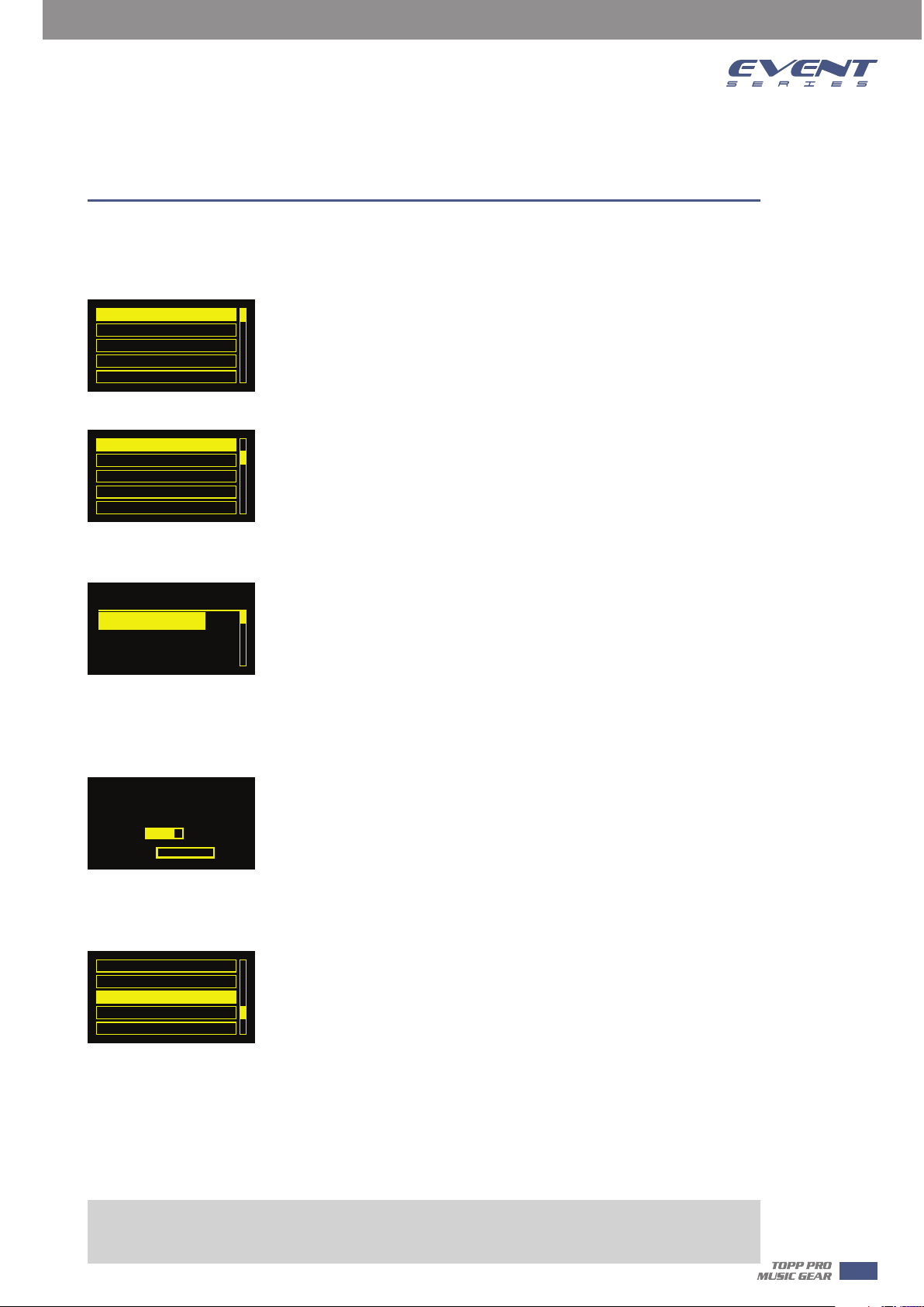
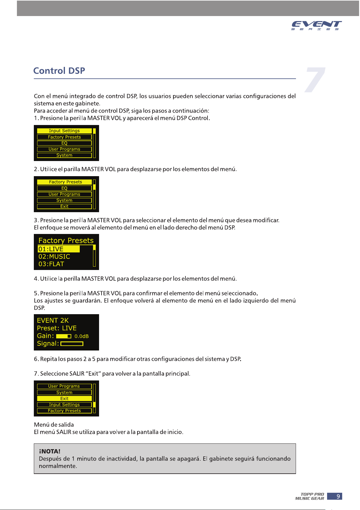
With the integrated DSP control menu, users can select multiple DSP system settings on the speaker.
To access the DSP Control menu, follow below steps:
1. Press the MASTER VOL knob and the DSP Control menu will appear.
Input Settings
Factory Presets
EQ
User Programs
System
2. Use the MASTER VOL knob to scroll through the menu items.
Factory Presets
EQ
User Programs
System
Exit
3. Press the MASTER VOL knob to select the menu item you want to modify.
The focus will move to the menu item on the right side of the DSP menu.
Factory Presets
01:LIVE
02:MUSIC
03:FLAT
7
4. Use the MASTER VOL knob to scroll through the menu items.
5. Press the MASTER VOL knob to confirm the selected menu item.
The settings will be saved. The focus will return to the menu item on the left side of the DSP menu.
EVENT 2K
Preset: LIVE
Gain:
0.0dB
Signal:
6. Repeat steps 2 through 5 to modify other DSP and system settings.
7. Select EXIT to return to the main screen.
User Programs
System
Exit
Input Settings
Factory Presets
Full range speaker DSP control menu
Full range speaker DSP control menu options are available for speakers.
EXIT menu
The EXIT menu is used to return to the home screen.
NOTE!
After 1 minutes of inactivity, the display will turn off. The speaker works properly.
9
Page 10
7
DSP Control
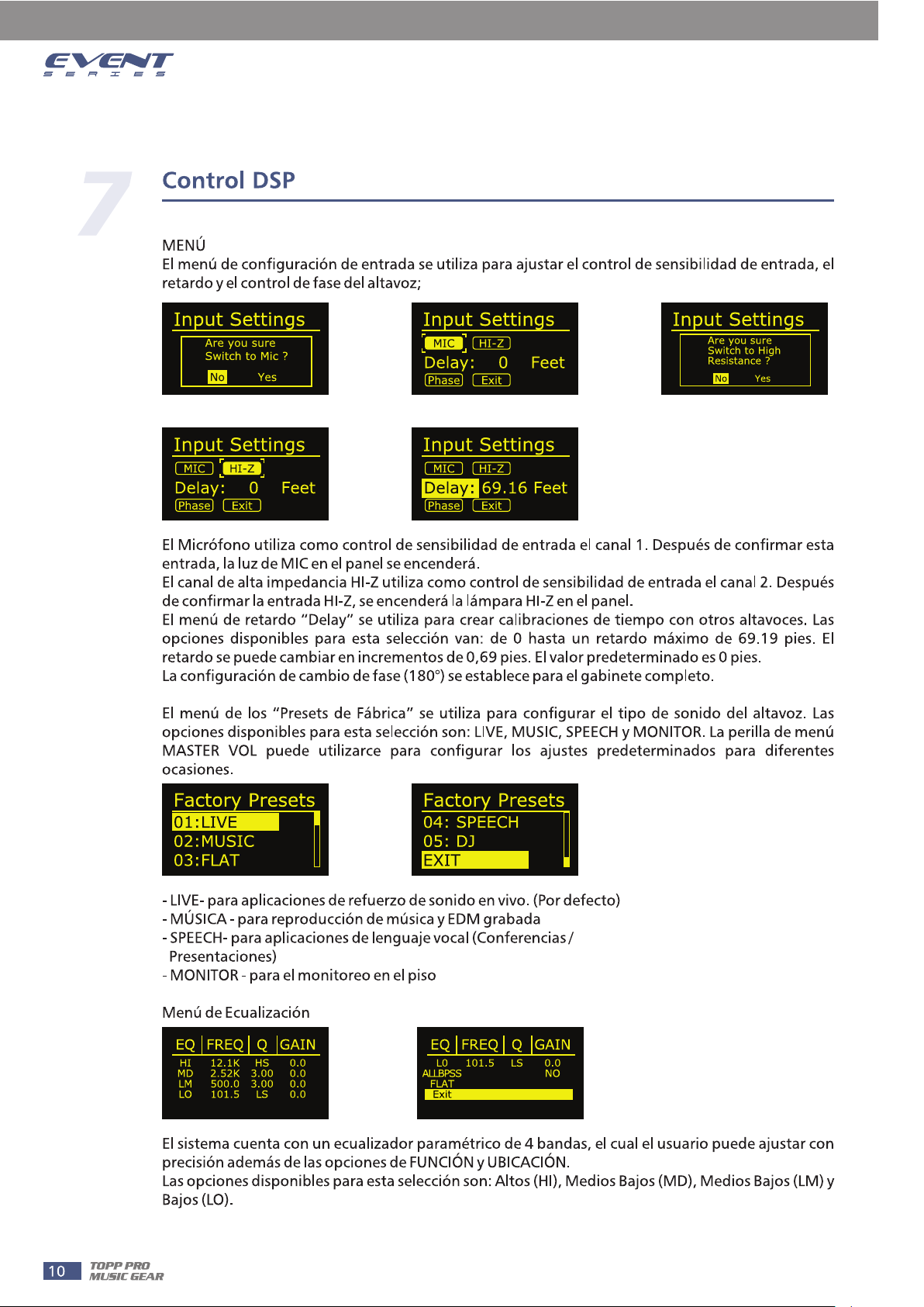
MENU
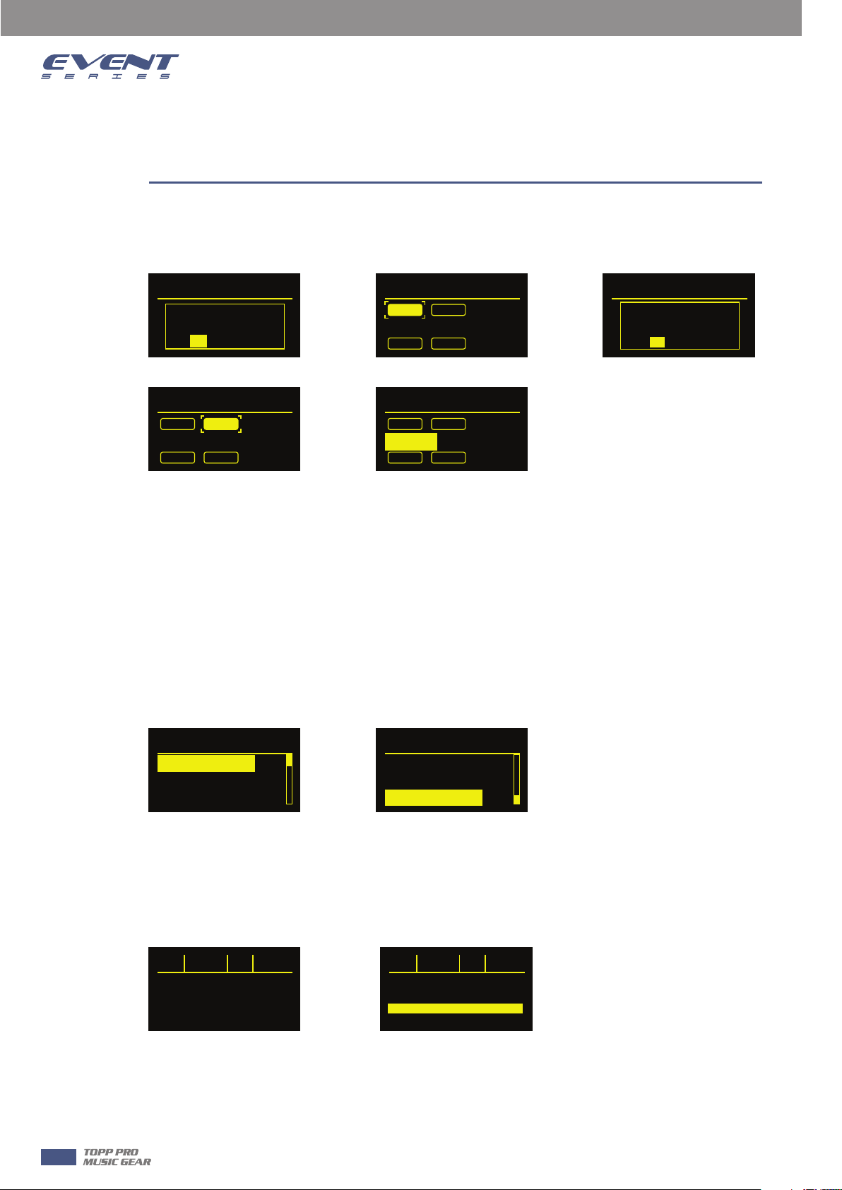
The Input Settings menu is used to configure the speaker's input sensitivity control and Delay and Phase
control;
Input Settings
Are you sure
Switch to Mic ?
No
Yes
Input Settings
MIC
Delay: 0 Feet
Phase Exit
HI-Z
Input Settings
Are you sure
Switch to High
Resistance ?
YesNo
Input Settings
MIC HI-Z
Delay: 0 Feet
Phase Exit
The MIC is used as the Input 1 input sensitivity control. After confirming the MIC input, the MIC light on the
panel will light up.
HI-Z is used as the input 2 input sensitivity control. After confirming the HI-Z input, the HI-Z lamp on the
panel will light up.
The Delay menu is used to create time calibrations with other speakers. The options available for this
selection are: 0 or a maximum delay of 69.19 Feet. The delay can be changed in increments of 0.69 Feet. The
default is 0 Feet.
Phase setting is set for the entire loudspeaker system;
The Factory Presets menu is used to configure the type of sound that the speaker sends. The options
available for this selection are: LIVE, MUSIC, SPEECH, and MONITOR. The MASTER VOL menu button can be
used to configure the presets for different occasions.
Factory Presets
01:LIVE
02:MUSIC
03:FLAT
Input Settings
MIC HI-Z
Delay: 69.16 Feet
Phase Exit
Factory Presets
04: SPEECH
05: DJ
EXIT
10
- LIVE- for live sound reinforcement applications. (Defaults)
- MUSIC - for recording music playback and EDM applications.
- SPEECH- for vocal language applications.
- MONITOR - for ground monitoring
EQ menu
EQ FREQ Q GAIN
0.0
HS
12.1K
HI
2.52K
MD
500.0
LM
101.5
LO
The EQ menu is a 4-band EQ (equalizer) that the user can fine tune in addition to FUNCTION and LOCATION.
The options available for this selection are: HI, MD, LM, and LO.
3.00
3.00
LS
0.0
0.0
0.0
EQ FREQ Q GAIN
101.5 LS 0.0
L0
ALLBPSS
FLAT
Exit
NO
Page 11
DSP Control
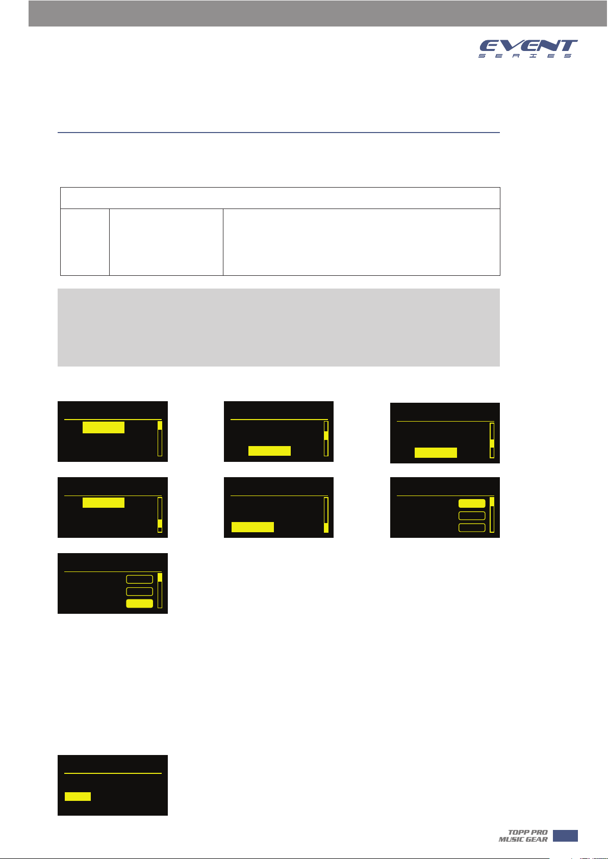
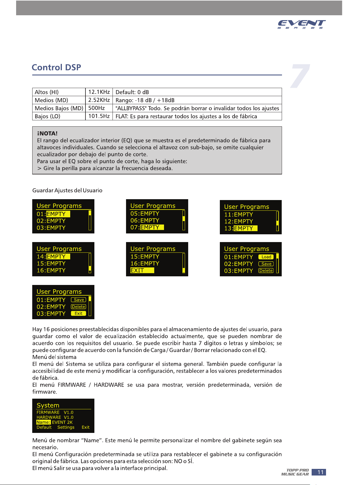
The EQ menu is a 4-band EQ (equalizer) that the user can fine tune in addition to FUNCTION and LOCATION.
The options available for this selection are: HI, MD, LM, and LO.
Back
7
HI
MD
LM
LO
NOTE!
The indoor equalizer (EQ) range shown is the factory default range for individual speakers. When the
woofer is selected, any EQ below the crossover point is bypassed.
To use EQ above the crossover point, do the following:
> Rotate the button to reach the desired frequency.
User Programs user save settings
User Programs
01:EMPTY
02:EMPTY
03:EMPTY
User Programs
14:EMPTY
15:EMPTY
16:EMPTY
12.1K
2.52K
500.0
101.5
Default: 0 decibels
Range: -18 decibels – +18 decibels
ALLBYPASS will be deleted, invalidating all set EQs.
FLAT is to restore all the adjusted EQ to factory settings.
User Programs
05:EMPTY
06:EMPTY
07:EMPTY
User Programs
15:EMPTY
16:EMPTY
EXIT
User Programs
11:EMPTY
12:EMPTY
13:EMPTY
User Programs
01:EMPTY
02:EMPTY
03:EMPTY
Load
Save
Delete
User Programs
01:EMPTY
02:EMPTY
03:EMPTY
There are 16 presets available for user storage, stored as the currently set EQ value, which can be named
according to user requirements. It can be written in 7-digit English or letters and symbols; it can be set
according to the load/Save/Delete related EQ.
System menu
The System menu is used to configure the system. You can also configure the accessibility of this menu and
modify the settings, reset to factory defaults.
The FIRMWARE / HARDWARE menu is used to display, preset version, firmware version.
Save
Delete
Exit
System
FIRMWARE V1.0
HARDWARE V1.0
Name: EVENT 2K
Default Settings Exit
11
Page 12
7
DSP Control
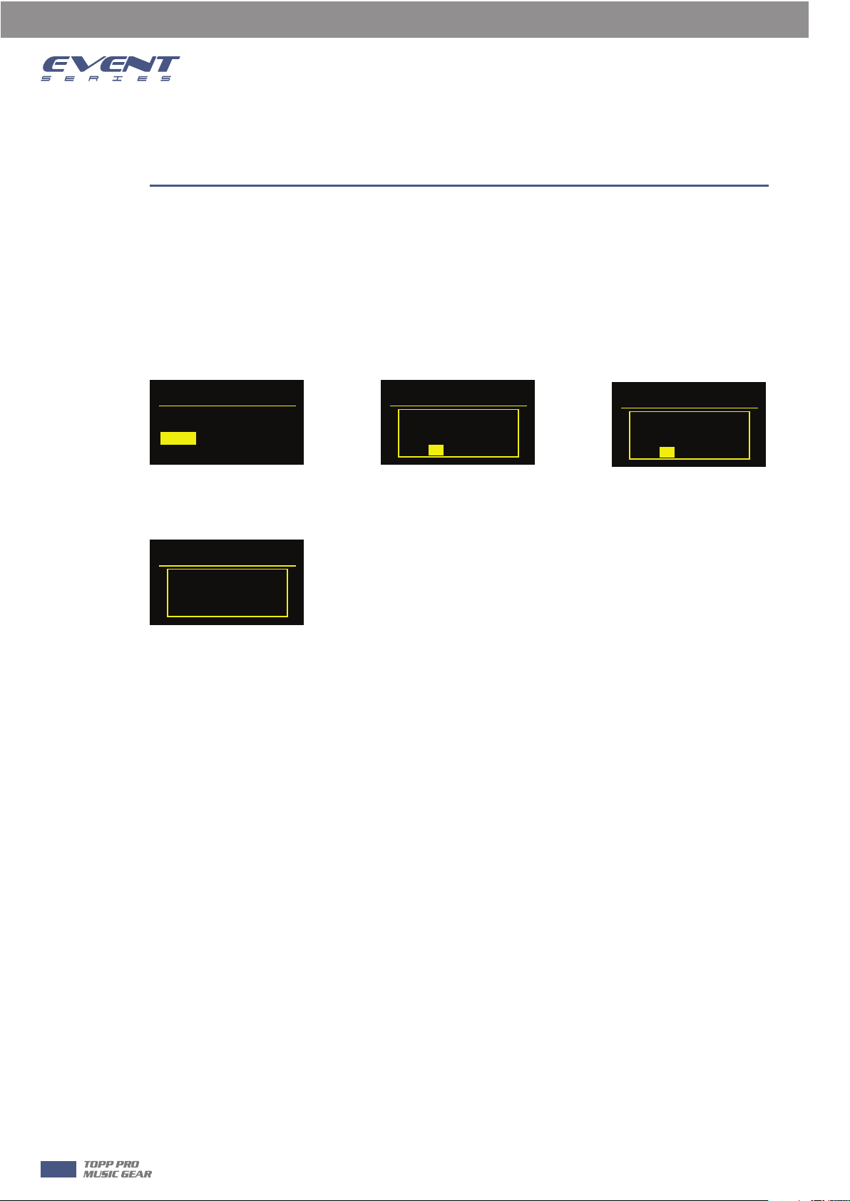
The Name menu is the name of the current speaker. This menu allows you to customize the name of the
speaker as needed.
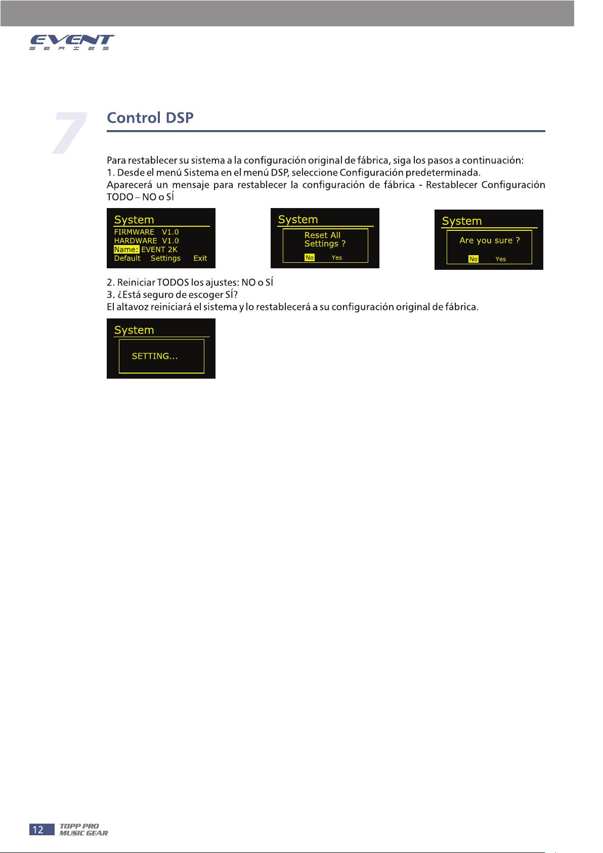
The Default Settings menu is used to reset the speakers to their original factory settings. The options for this
selection are: NO or YES.
The Exit menu is used to return to the main interface.
To reset your system to original factory settings, follow below steps:
1. From the System menu in the DSP menu, select Default Settings.
A message prompt to restore the factory settings will appear - Reset ALL Setting - YES.
System
FIRMWARE V1.0
HARDWARE V1.0
Name: EVENT 2K
Default Settings Exit
2. Reset ALL Setting select YES
3. Are you sure choose YES
The speaker will reboot the system and reset the system to its original factory settings.
System
SETTING...
System
System
Reset All
Settings ?
YesNo
Are you sure ?
YesNo
12
Page 13
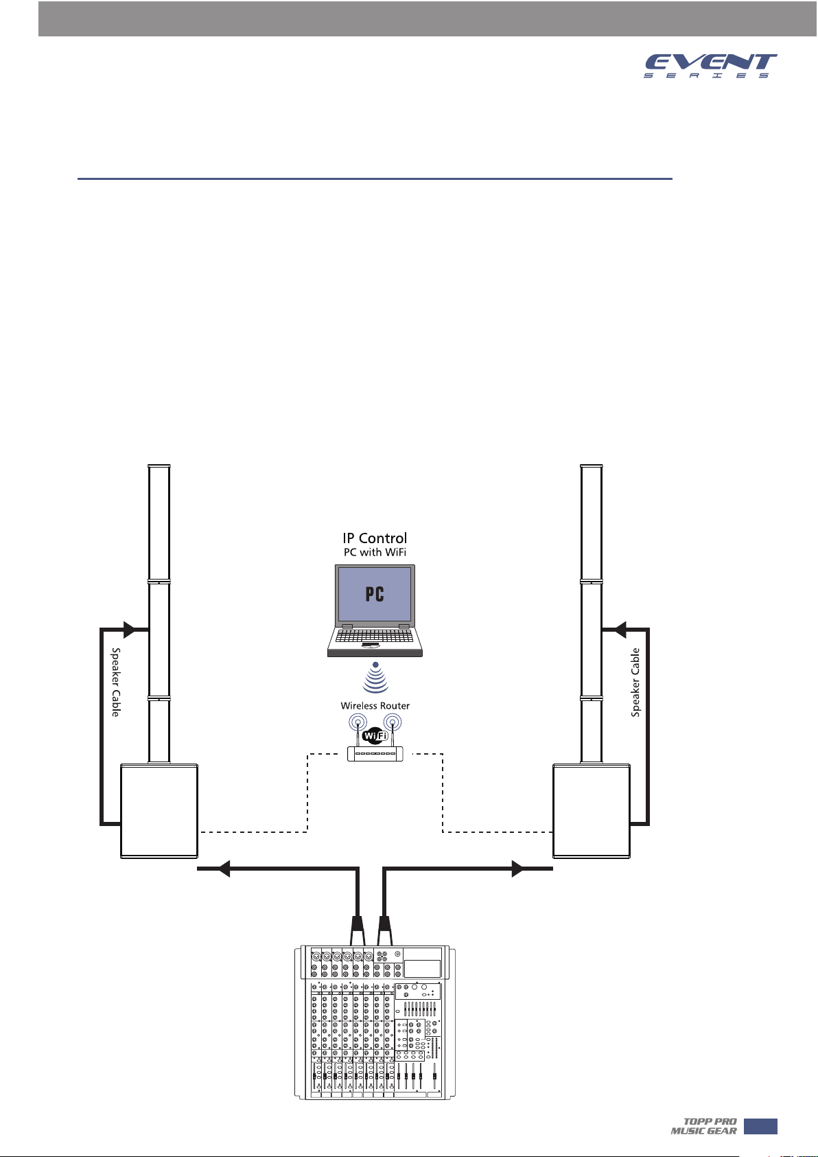
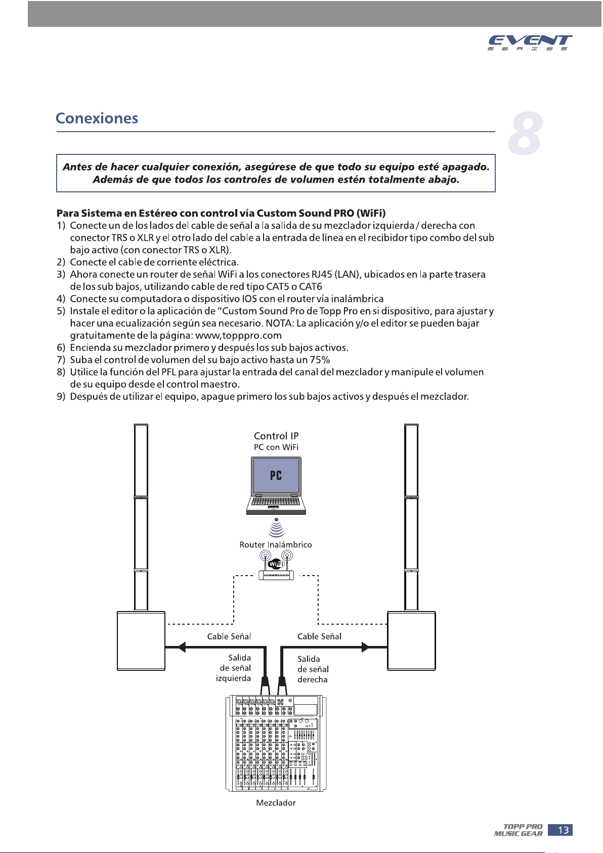
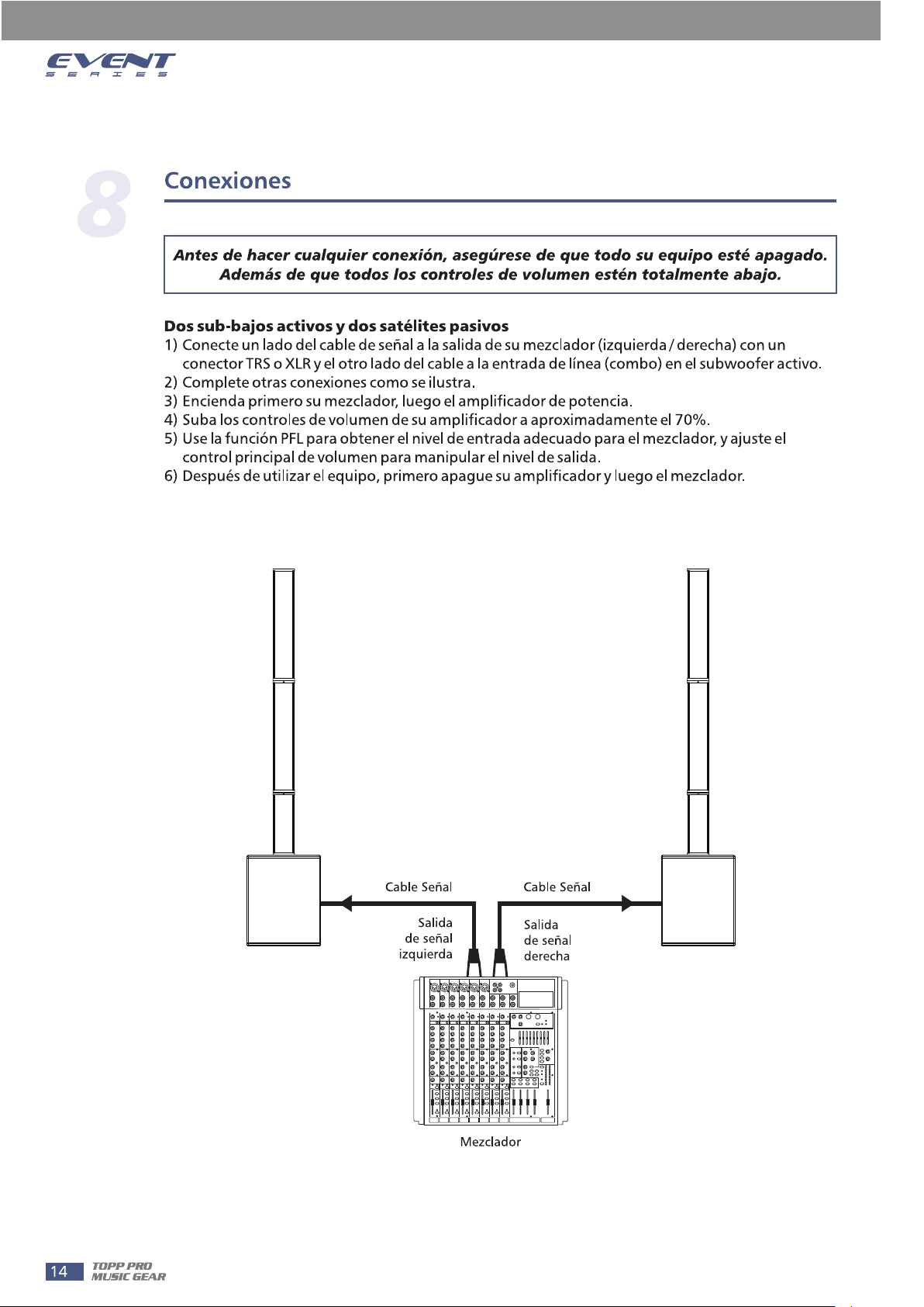
Connection Plate System
Make your initial connections with all the equipment powered off, and ensure that all the main
volume controls are turned completely down.
Two Active Subwoofers & Two Passive Satellite Speakers
1) Connect one side of the signal cable to the output of your mixer (left / right) with a TRS or
XLR connector and the other side of the cable to the line input (combo) in the active
subwoofer (with a TRS to XLR connector). Then connect the speakon cable from the output
of power in the Subwoofer to the satellites input.
2) Complete other connections as illustrated.
3) Turn on your mixer first, then the stereo power amplifier.
4) Turn up the volume controls of your amplifier to about70%.
5) Use PFL function to get the proper input level for the mixer, and adjust the Mian Mix Level
control to manipulate the output level.
6) After using, turn off your stereo power amplifier first, then the mixer.
8
Signal Cable
Left
Main Mix
Output
Signal Cable
Right
Main Mix
Output
Mixer
13
Page 14
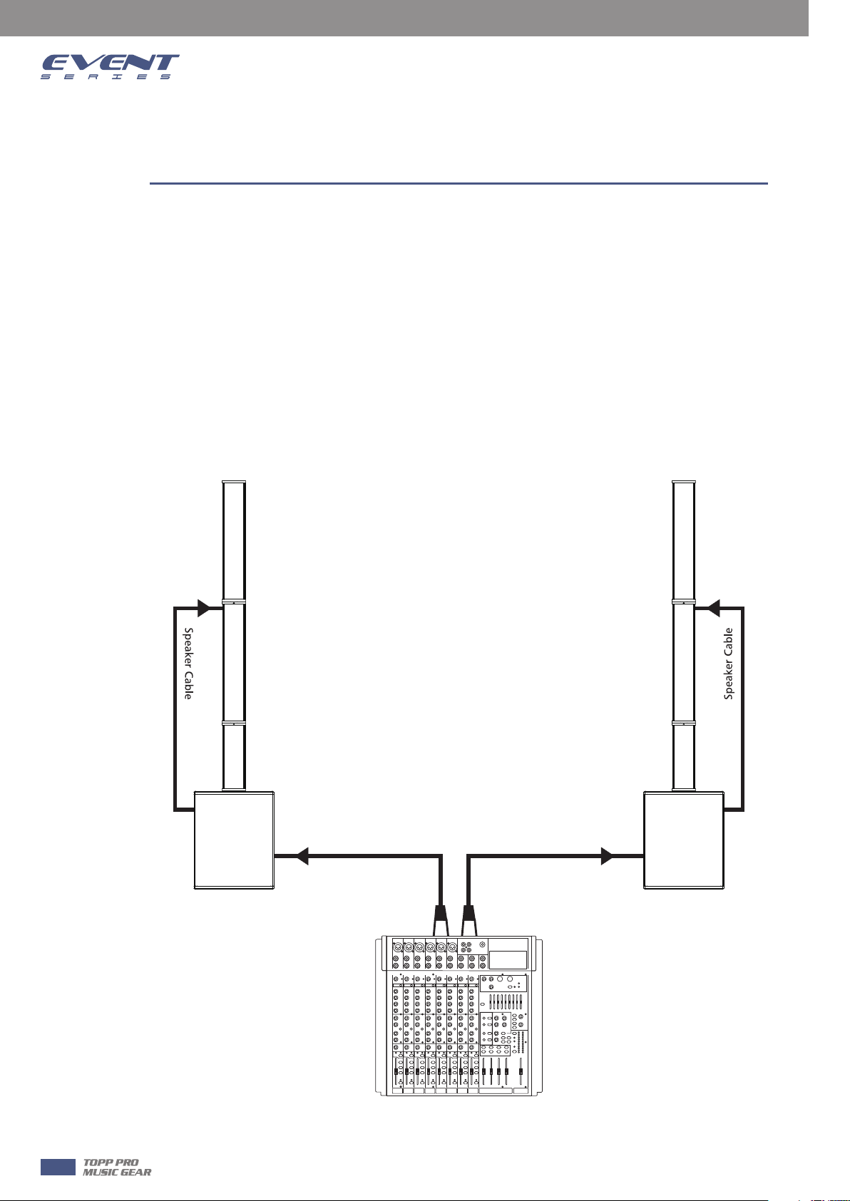
Connection Plate System
8
Make your initial connections with all the equipment powered off, and ensure that all the
main volume controls are turned completely down.
1) Connect one side of the signal cable at your audio mixer into output left / right (with
Stereo-Jack or XLR) and the other side of the cable into the line input (Stereo-Jack) of your active
speaker cabinet.
2) Connect the power cord to mains.
3) Turn on your mixer first, then the active speaker cabinets.
4) Turn up the volume control of the active speaker cabinets.
5) Use PFL function to get the proper input level for the mixer, and adjust the Main Mix Level
control to manipulate the output level.
6) After using, turn off your stereo power amplifier first, then the mixer.
14
Signal Cable
Left
Main Mix
Output
Signal Cable
Right
Main Mix
Output
Mixer
Page 15
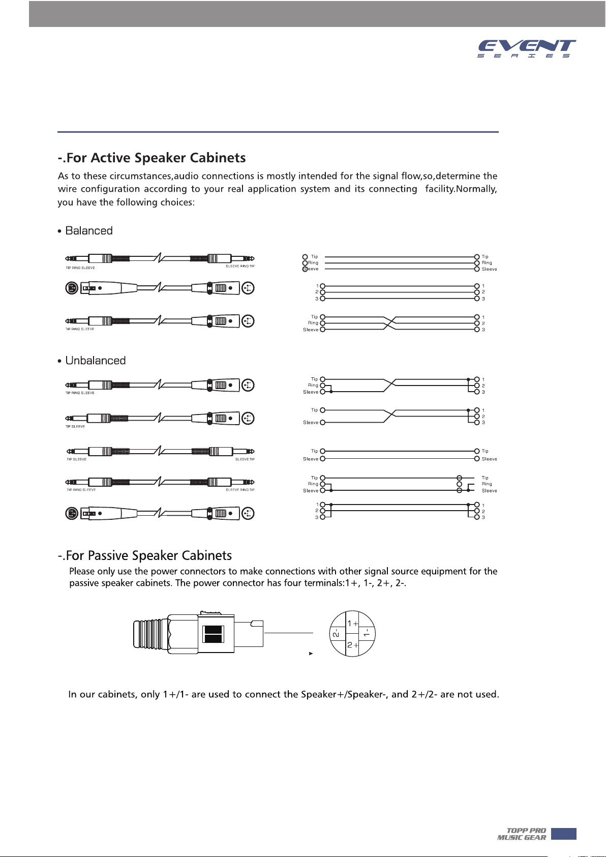
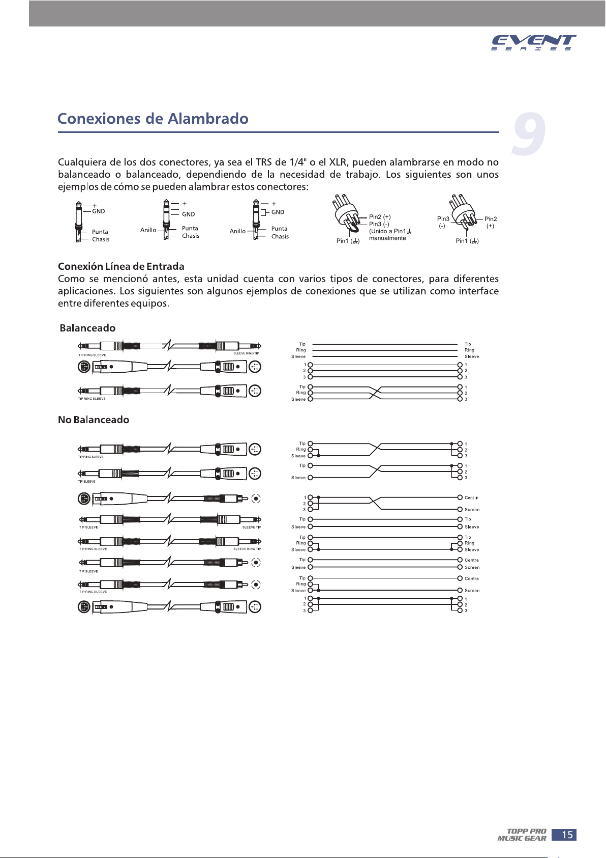
Wire Connections
9
15
Page 16
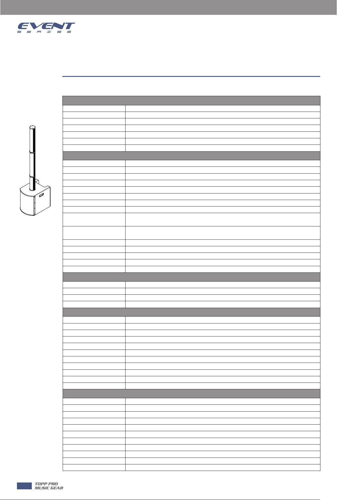
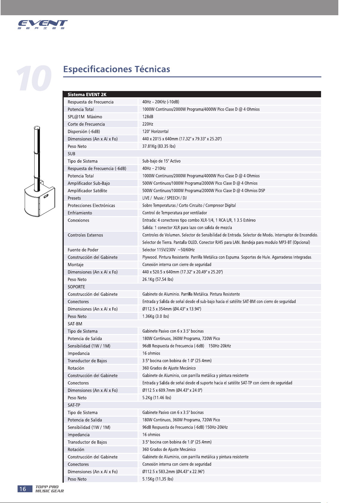
Technical Specifications
10
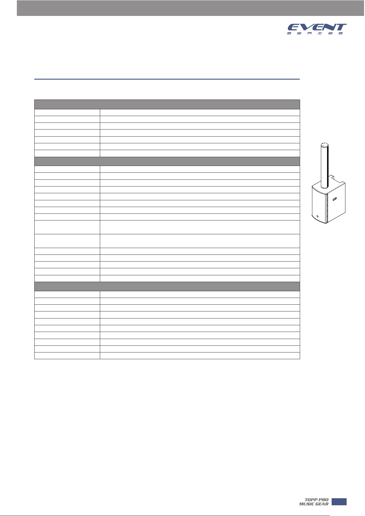
EVENT 2K SYSTEM: SUB+POLE+SAT-BM+SAT-TP
EVENT 2K System
Frequency Response
Total Amplifier Power
Maximum SPL@1M 128dB
Crossover Frequency
Dispersion(-6dB)
Dimensions(WxHxD) 440 x 2015 x 640mm (17.32'' x 79.33'' x 25.20'')
Net Weight 37.81Kg (83.35 Ibs)
SUB
System Type 15" Acve Subwoofer Speaker Cabinet
Frequency Response(-6dB)
Total Amplifier Power
Amplifier, Subwoofer
Amplifier, Satellite
DSP Presets Modes
Electronic Protec�ons Over heat Protecon/Short Circuit Protecon/Digital Compressor
Cooling Temperature-controlled fan
Connec�ons Input: 4 x Combo-XLR&1/4”, 1
External Controls
Power Supply 115V/230V ~50/60Hz Switchable
Enclosure Construc�on
Moun�ng Smart Mounng and Connecon
Dimensions(WxHxD) 440 x 520.5 x 640mm (17.32'' x 20.49'' x 25.20'')
Net Weight 26.1Kg (57.54 Ibs)
Pole
Enclosure Construc�on
Connector
Dimensions(WxHxD)
Net Weight
SAT-BM
Syste
m Type
Output Power
Sensi�vity (1W/1M)
Frequency Response(-6dB)
Impedance
Transducer Low
Rota�on
Enclosure Construc�on
Connector
Dimensions(WxHxD)
Net Weight
SAT-TP
System Type
Output Power
Sensi�vity (1W/1M)
Frequency Response(-6dB)
Impedance
Transducer Low
Rota�on
Enclosure Construc�on
Connector
Dimensions(WxHxD)
Net Weight
40Hz – 20KHz (-10dB)
1000W Connuous/2000W Program/4000W Peak Class D @ 4 Ohms
220Hz
120°Horizontal
40Hz – 210Hz
1000W C
500W Connuous/1000W Program/2000W Peak Class D @ 4 Ohms
500W Connuous/1000W Program/2000W Peak Class D @ 4 Ohms
LIVE / Music /FLAT / SPEECH / DJ
Output: 1 x XLR Thru&Mixout
Volume Control/Switch for Input sens/Swch for mode selector/Power ON with Green LED/
Limiter with Red LED/Ground Li/OLED DSP Display and Control /IP Control/MP3 and BT(opon)
Plywood Cabinet, Resistant Black Paint, Metal Grille with Foam, Rubber Feet, Integrated side handles
Aluminium Cabinet, Metal Grille, Resistant Paint
2 x Electronic Adapter - 1 x Input Connector for Sub & Another with Input Connector for Satellite
112.5 x 354mm(4.43'' x 13.94'')
1.36Kg (3.0 Ibs)
6 x 3.5" Passive Speaker System
180W Connuous, 360W Program, 720W Peak
96dB
150Hz-20kHz
16 ohms
3.5'' Woofer , 1.0'' (25.4mm) Voice Coil
360 Degree Mechanical Adjustment
Aluminium Cabinet, Metal Grille, Resistant Paint
2 x Electronic Adapter - 1 x Input Connector for AX Pole & Another with Input Connector for AXV62TP
112.5 x 609.7mm(4.43'' x 24.0'')
5.2Kg (11.46 Ibs)
6 x 3.5" Passive Speaker System
180W Connuous, 360W Program, 720W Peak
96dB
150Hz-20kHz
16 ohms
3.5'' Woofer , 1.0'' (25.4mm) Voice Coil
360 Degree Mechanical Adjustment
Alum
2 Pin smart connecon
112.5 x 583.2mm(4.43'' x 22.96'')
5.15Kg (11.35 Ibs)
onnuous/2000W Program/4000W Peak Class D @ 4 Ohms
x RCA In L&R, 1 x 3.5 Stereo Jack,
inium Cabinet, Metal Grille, Resistant Paint
16
Page 17
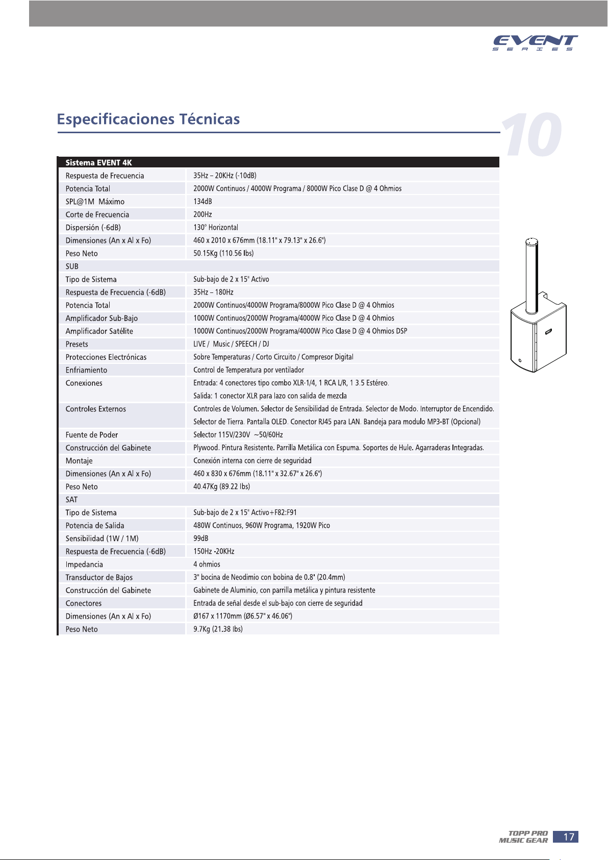
Technical Specifications
EVENT 4K SYSTEM: SUB+SAT
EVENT 4K SYSTEM
Frequency Response
Total Amplifier Power
Maximum SPL@1M 134dB
Crossover Frequency
Dispersion(-6dB)
Dimensions(WxHxD) 460 x 2010 x 676mm (18.11'' x 79.13'' x 26.6'')
Net Weight 50.15Kg (110.56 Ibs)
SUB
System Type 2 x 15" Acve Subwoofer Speaker Cabinet
Frequency Response(-6dB)
Total Amplifier Power
Amplifier, Subwoofer
Amplifier, Satellite
DSP Presets Modes
Electronic Protec�ons Over heat Protecon/Short Circuit Protecon/Digital Compressor
Cooling Temperature-controlled fan
Connec�ons Input: 4 x Combo-XLR
External Controls
Power Supply 115V/230V ~50/60Hz Switchable
Enclosure Construc�on
Moun�ng Smart Mounng and Connecon
Dimensions(WxHxD) 460 x 830 x 676mm (18.11'' x 32.67'' x 26.6'')
Net Weight 40.47Kg (89.22 Ibs)
SAT
System Type
Output Power
Sensi�vity (1W/1M)
Frequency Response(-6dB)
Impedance
Transducer Low
Enclosure Con
Connector
Dimensions(WxHxD)
Net Weight
struc�on
35Hz – 20KHz (-10dB)
2000W Connuous / 4000W Program / 8000W Peak Class D @ 4 Ohms
200Hz
130°Horizontal
35Hz – 180Hz
2000 W C
1000 W Connuous / 2000W Program/4000W Peak Class D @ 4 Ohms
1000 W Connuous / 2000W Program/4000W Peak Class D @ 4 Ohms
LIVE / Music / SPEECH / DJ
Output: 1 x XLR Thru&Mixout
Volume Control/Switch for Input sens/Swch for mode selector/Power ON with Green LED/Limiter
with Red LED/Ground Li/OLED DSP Display and Control /IP Control/MP3 and BT(opon)
Plywood Cabinet, Resistant Black Paint, Metal Grille with Foam, Rubber Feet, Integrated side handles
24*3" Passive Speaker System
480W Connuous, 960W Program, 1920W Peak
99dB
150Hz-20kHz
4 ohms
3'' Neodymium Fullrange Speaker, 0.8'' (20.4mm) Voice Coil
Aluminium Cabinet, Metal Grille, Resistant Paint
2 Pin smart connecon
167 x 1170mm(6.57'' x 46.06'')
9.7Kg (21.38 Ibs)
onnuous / 4000W Program/8000W Peak Class D @ 4 Ohms
&1/4”, 1 x RCA In L&R, 1 x 3.5 Stereo Jack,
10
17
Page 18
DSP software connection / IP Control instruction
11
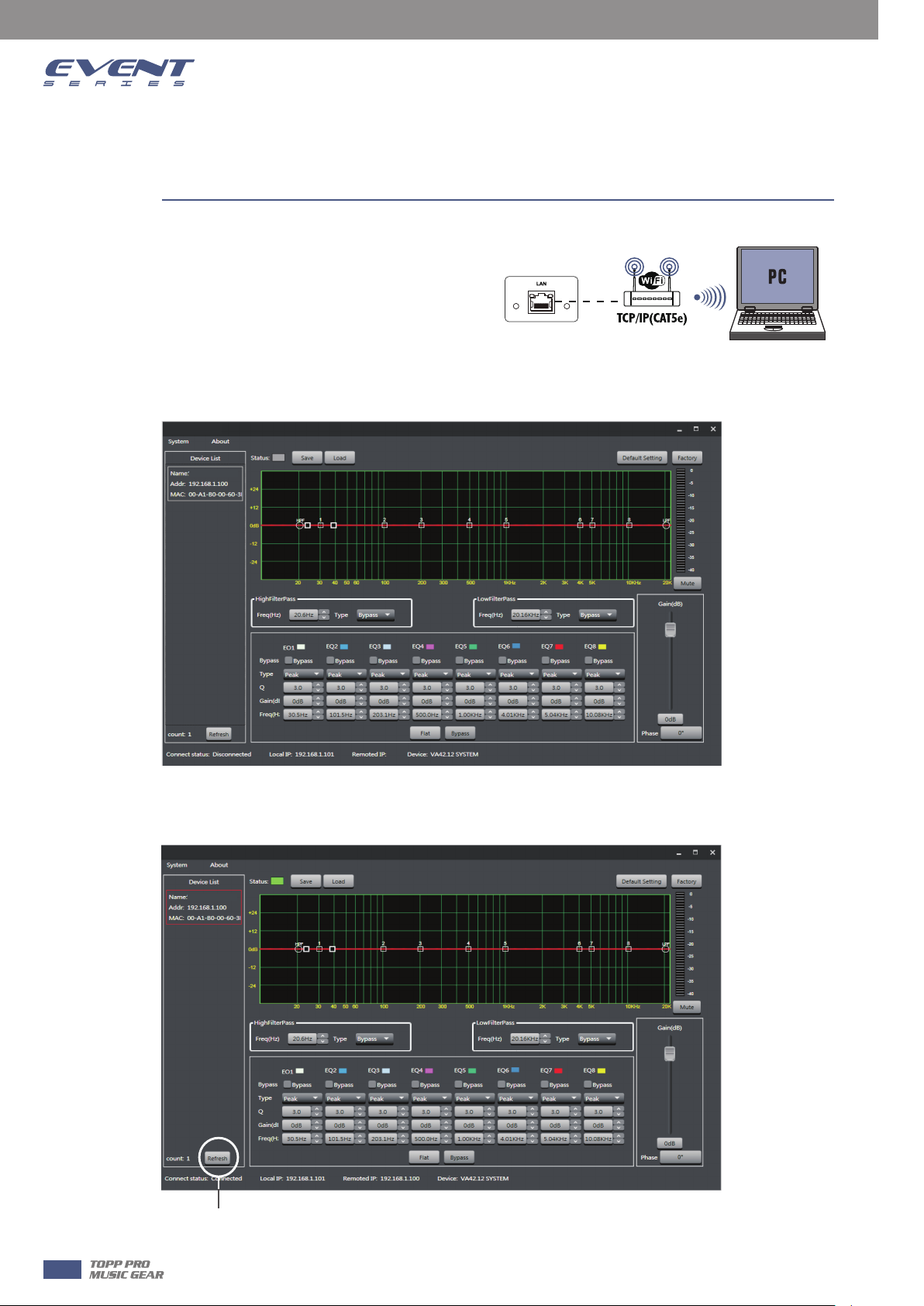
1. List of required materials
Computer(window system7-10)*1
Router*1
Network cable *1
CS PRO_1.09 software*1
EVENT 2K / EVENT 4K SYSTEM *1PCS
2. Connect the router to the module network port and turn on the power.
3. Make the computer connect to the router and open software “CS PRO_V1.0.9”
EVENT 2K
5. Click the “Refresh”,and Click the “Device List” that appears. After the connection is OK, you
can make initial debugging on this user page.
EVENT 2K
Click
18
Page 19
12
19
Page 20

Page 21
Page 22
Page 23
Page 24
Page 25
Page 26
Page 27
Page 28
Page 29
Page 30
Page 31
Page 32
Page 33
Page 34
Page 35
Page 36
Page 37
Page 38
Page 39

 Loading...