

Topp Music Gear TXO-234 MK II User Manual

2-way/3-way stereo /4-way mono
USER's MANUAL
ACTIVE CROSSOVER
TXO-234 MK II
SAFETY RELATED SYMBOLS
CAUTION
RISK OF ELECTRIC SHOCK
DO NOT OPEN
This symbol, wherever used, alerts
you to the presence of un-insulated
and dangerous voltages within the
product enclosure. These are voltages
that may be sufficient to constitute the
risk of electric shock or death.
WARNING
Describes precautions that should be
observed to prevent the possibility of
death or injury to the user.
Describes precautions that should be
observed to prevent damage to the
product.
CAUTION
Operating Conditions
Always install in accordance with the
manufacturer's instructions.
This symbol, wherever used, alerts
you to important operating and maintenance instructions. Please read.
Protective Ground Terminal
AC mains (Alternating Current)
Hazardous Live Terminal
ON:
OFF:
Denotes the product is turned on.
Denotes the product is turned off.
WARNING
Power Supply
Ensure that the mains source voltage (AC
outlet) matches the voltage rating of the
product. Failure to do so could result in
damage to the product and possibly the user.
External Connection
Do not Remove any Covers
Fuse
To prevent fire and damage to the
product, use only the recommended
fuse type as indicated in this manual.
Do not short-circuit the fuse holder.
Before replacing the fuse, make sure
that the product is OFF and disconnected
from the AC outlet.
Always use proper ready-made insulated
mains cabling (power cord). Failure to do
so could result in shock/death or fire. If
in doubt, seek advice, from a registered
electrician.
Within the product are areas where high
voltages may present. To reduce the risk
of electric shock do not remove any
covers unless the AC mains power cord
is removed.
Covers should be removed by qualified
service personnel only.
No user serviceable parts inside.
Unplug the product before electrical storms
occur and when unused for long periods of
time to reduce the risk of electric shock or
fire.
Protective Ground
Before turning the product ON, make sure
that it is connected to Ground. This is to
prevent the risk of electric shock.
Never cut internal or external Ground wires.
Likewise, never remove Ground wiring
from the Protective Ground Terminal.
Disposing of this product should
not be placed in municipal waste
and should be separate collection.
1111
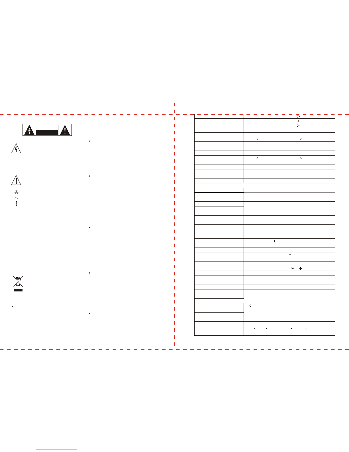
CONTROLS
Xover Frequency
Delay
Input
Gain
Threshold
POWER SUPPLY
Mains Voltages
Power Consumption
Fuse
Mains Connection
PHYSICAL
Dimensions
Net Weight
CD Horn
Limiter
Rear Panel
Xover Frequency
Mode
LF Sum
CROSSOVER
Filter Type
Stereo Mode Frequencies
Low/High
Low/Mid
Mid/High
Mono Mode Frequencies
Low/Low-Mid
Low-Mid/High-Mid
High-Mid/High
FUNCTION SWITCHES
Front Panel
Phase Invert
Low Cut
Mute
ON=Channel 1 6dB louder / Channel 2: the
Corrects CD horn frequency response above
3.5 kHz
Activates the limiter function for all outputs
Multiplies crossover frequency range by 10
Selects stereo/mono and 2/3/4-way operation
Selects normal stereo or mono-summed low
frequency operation
High to High-Mid:
High-Mid to Low-Mid:
Low-Mid to Low:
95 dB
95 dB
92 dB
Linkwitz-Riley, 24 dB/Octave, state-variable
44 to 930 Hz
44 to 930 Hz
440 Hz to 9.3 kHz
44 to 930 Hz
440 Hz to 9.3 kHz
440 Hz to 9.3 kHz
1
10
1
10
440 Hz to 9.3 kHz
440 Hz to 9.3 kHz
440 Hz to 9.3 kHz
Activates 25 Hz Butterworth, 12 dB/Octave
high-pass filter
Mutes the individual output
Inverts the phase at the individual output
Controls the input gain (- to +12 dB)
Controls the crossover frequency
Controls the delay at the low output (0 to 2 msec.)
U.K./Australia
Europe
General Export Model
95-120V: 500mA 250VAC
Controls the output gain (- to 6 dB)
Controls the threshold of the limiter ( 6 dB to OFF)
USA/Canada
230 V~, 50 Hz
95-120 V~, 210-240 V~, 50-60 Hz
17W
210-240V: T250mAL 250VAC
Standard IEC receptacle
3 kg(6.61 lb)
483 194.5 44mm/19(W)" 7.7(D)" 1.7(H)"
same as before
120 V~, 60 Hz
240 V~, 50 Hz
Non-use Periods:
Object and Liquid Entry:
Damage Requiring Service:
Servicing:
The user should not attempt to service the appliance beyond that is describedin the
Instructions.All other servicing should be referred to qualifield service personnel.
The power cord of the appliance should be unplugged from the outlet when left unused
for a long period of time.
Care should be taken so that objects do not fall and liquids are not spilled into the enclosure
through openings.
The appliance should be serviced by qualified service personnel when:
-The power supply cord or the plug has been damaged; or
-Objects have fallen,or liquid has been spilled into the appliance; or
-The appliance has been exposed to rain; or
-The appliance dose not appear to operate normally or exhibits a marked change in
performance; or
-The appliance has been dropped, or the enclosure damaged.
Operating
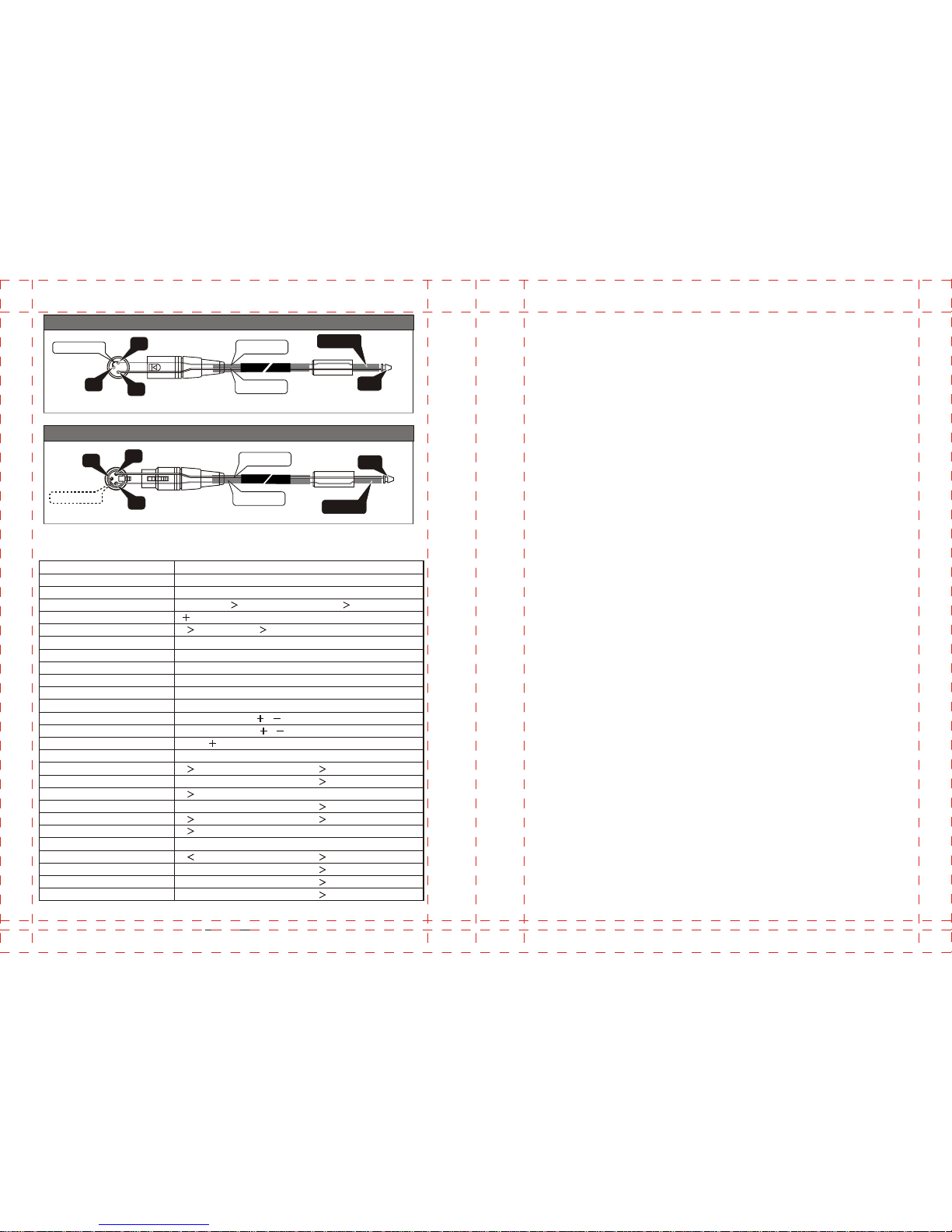
SPECIFICATIONS
XLR-F-JACK unbalanced link
1
2
3
LINK 3 to 1
GROUND
SIGNAL
SLEEVE
TIP
XLR-M-JACK unbalanced link
LINK 3 to 1
1
2
3
GROUND
SIGNAL
TIP
SLEEVE
1010
Bandwidth
20 Hz to 20 kHz, 0/ 0.5 dB
+5 Hz to -90 kHz, 0/ 3 dB
Ref.: 4 dBu, 20 Hz to 20 kHz, unweighted
Stereo Mode:
93 dB
94 dB
95 dB
94 dB
90 dB
106 dB, unweighted
Frequency Response
Dynamic Range
High Output
High-Mid Output
Mid Output
Low-Mid Output
Low Output
Signal to Noise Ratio
93 dB
88 dB
Mono Mode:
PERFORMANCE
INPUT
XLR
Electronically servo-balanced, RF filtered
Balanced 50k Ohms, unbalanced 25k Ohms
22 dBu typical, balanced or unbalanced
40 dB, typically 55 dB at 1 kHz
OUTPUT
Connectors
Electronically servo-balanced, RF filtered
Balanced 60 Ohms, unbalanced 30 Ohms
+20 dBm balanced/unbalanced
Connectors
Type
Impedance
Impedance
Max. Output Level
Type
XLR
Max. Input level
CMRR
Limiter Off
0.04%
High to Low:
High to Mid:
Mid to Low:
Interchannel Crosstalk
THD & Noise
Limiter On
93 dB
94 dB
95 dB
0.5
 Loading...