

Topp Music Gear TPS BETA1152A, TPS BETA1152, TPS BETA2152, TPS BETA15 SUB, TPS BETA2152A User Manual
...
PRO-CONCERT LEVEL PASSIVE / ACTIVE AUDIO ENCLOSURES
User’s Manual
TPS BETA1152/1152A TPS BETA2152/2152A
TPS BETA15/18/218 SUB TPS BETA15A/18A SUB
l
l
Safety Related Symbols
Protective Ground
Before turning the unit ON, make sure that it is
connected to Ground. This is to prevent the risk of
electric shock.
Never cut internal or external Ground wires. Like wise,
never remove Ground wiring from the Protective
Ground Terminal.
Operating Conditions
Always install in accordance with the manufacturer's
instructions.
To avoid the risk of electric shock and damage, do not
subject this product to any liquid/rain or moisture.
Do not use this product when in close proximity to
water.
Do not install this product near any direct heat source.
Do not block areas of ventilation. Failure to do so
could result in fire.
Keep product away from naked flames.
IMPORTANT SAFETY INSTRUCTIONS
Read these instructions
Follow all instructions
Keep these instructions. Do not discard.
Heed all warnings.
Only use attachments / accessories specified by the
manufacturer.
Power Cord and Plug
Do not tamper with the power cord or plug. These are
designed for your safety.
Do not remove Ground connections!
If the plug does not fit your AC out let seek advice
from a qualified electrician.
Protect the power cord and plug from any physical
stress to avoid risk of electric shock.
Do not place heavy objects on the power cord. This
could cause electric shock or fire.
Cleaning
When required, either blow off dust from the product
or use a dry cloth.
Do not use any solvents such as Benzol or Alcohol.
For safety, keep product clean and free from dust.
Servicing
Refer all servicing to qualified service personnel only.
Do not perform any servicing other than those
instructions contained within the User's Manual.
CAUTION
RISK OF ELECTRIC SHOCK
DO NOT OPEN
2
TOPP PRO
MUSIC GEAR
PORTABLE
CART WARNING
Carts and stands - The
component should be used
only with a cart or stand
that is recommended by
the manufacturer.
A component and cart
combination should be
moved with care. Quick
stops, excessive force,
and uneven surfaces may
cause the component and
cart combination to
overturn.
This symbol, wherever used, alerts you to the presence
of un-insulated and dangerous voltages within the
product enclosure. These are voltages that may be
sufficient to constitute the risk of electric shock or
death.
This symbol, wherever used, alerts you to important
operating and maintenance instructions.
Please read.
Protective Ground Terminal
AC mains (Alternating Current)
AC mains (Alternating Current)
Denotes the product is turned on.
Denotes the product is turned off.
WARNING
Describes precautions that should be observed to
prevent the possibility of death or injury to the user.
CAUTION
Describes precautions that should be observed to
prevent damage to the product.
Disposing of this product should not be placed in
municipal waste but rather in a separate collection.
WARNING
Power Supply
Ensure that them a inssource voltage (AC outlet)
matches the voltage rating of the product. Failure to
do so could result in damage to the product and
possibly the user. Unplug the product before electrical
storms occur and when unused for long periods of
time to reduce the risk of electric shock or fire.
External Connection
Always use proper ready-made insulated mains
cabling (power cord). Failure to do so could result in
shock/death or fire. If in doubt, seek advice from a
registered electrician.
Do Not Remove Any Covers
Within the product are areas where high voltages may
present. To reduce the risk of electric shock do not
remove any covers unless the AC mains power cord is
removed. Covers should be removed by qualified
service personnel only.
No user serviceable parts inside.
Fuse
To prevent fire and damage to the product, use only
the recommended fuse type as indicated in this
manual. Do not short-circuit the fuse holder. Before
replacing the fuse, make sure that the product is OFF
and disconnected from the AC outlet.
Table of Contents
1. PROLOGUE
2. INSTALLATION TIPS
3. USEFULL DATA
4. CONNECTING DIAGRAM
For Passive Speaker Cabinet
For Passive Subwoofer & Satellite Speakers
For Active Speaker Cabinet
For Active Subwoofer & Satellite Speakers
5. CONNECTING PLATE
For Passive Series Speaker
For Active Full-range Speaker
For Active Subwoofer Speaker
6. WIRE CONNECTIONS
7. TECHNICAL SPECIFICATIONS
8. BLOCK DIAHGRAM
9. GUARANTEE

3
Table of Contents
Don’t forget to visit our website at www.topppro.com
for more information about this and other Topp Pro products.
4
4
4
5
10
12
13
18
20
1. PROLOGUE
2. INSTALLATION TIPS
3. USEFULL DATA
4. CONNECTING DIAGRAM
For Passive Speaker Cabinet
For Passive Subwoofer & Satellite Speakers
For Active Speaker Cabinet
For Active Subwoofer & Satellite Speakers
5. CONNECTING PLATE
For Passive Series Speaker
For Active Full-range Speaker
For Active Subwoofer Speaker
6. WIRE CONNECTIONS
7. TECHNICAL SPECIFICATIONS
8. BLOCK DIAHGRAM
9. GUARANTEE
TOPP PRO
MUSIC GEAR

Thank you for purchasing TOPP PRO MUSIC GEAR products BETA series speaker cabinet.
The cabinets are all plywood construction with our DURAPRO paint finish. The
components have been matched to offer the highest quality achievable.
The 3" Compression Driver and woofer reinforcement provided an excellent performance.
The BETA series speaker cabinets can be used for all type of applicatio nincluding but not
limit to churches, conferences room, disco and by live performance groups.
We believe with these features combination, the BETA series speaker cabinets not only
looks great, but also provides a perfect performance.
Speakers should be placed in a position that allows for unobstructed sound protection.
In many instances is beneficial for speakers to be elevated on tripod stands to achieve
maximum dispersion and reach.
Use professional advice or service when hanging and installing speakers. Please takes
precautions to secure the speakers to prevent them from falling and hurting someone,
secure the speaker could also prevent you from damaging the cabinet or its
components.
Use quality cables. Using quality cables ensure best possible sound.
For best results of the BETA passive cabinets, you can match the speaker to a good
amplifier that match the wattage and impedance of your speakers. Proper amplification
power result in good quality audio and longer component life. Check out the power
requirement for your cabinet. And match your BETA passive cabinets to a good mixer.
(Please refer to FIG. 1)
In some applications, matching the BETA passive cabinet with BETA subwoofers to
achieve bass reinforcement. (Please refer to FIG. 2 & FIG. 3)
For the BETA active cabinets there are no need amplifier so you can match them with a
good mixer.
Avoid pointing microphone directly at an amplified speaker; doing so could cause feed
back possibly damaging speaker components and your hearing.
(Please refer to FIG. 4 & FIG. 5)
Please write your serial number here for future reference.
4
Introduction
Usefull Tips
Serial Number:
Date of Purchase:
Purchased at:
Usefull Data
1
2
3
l
l
l
l
l
l
l
TOPP PRO
MUSIC GEAR
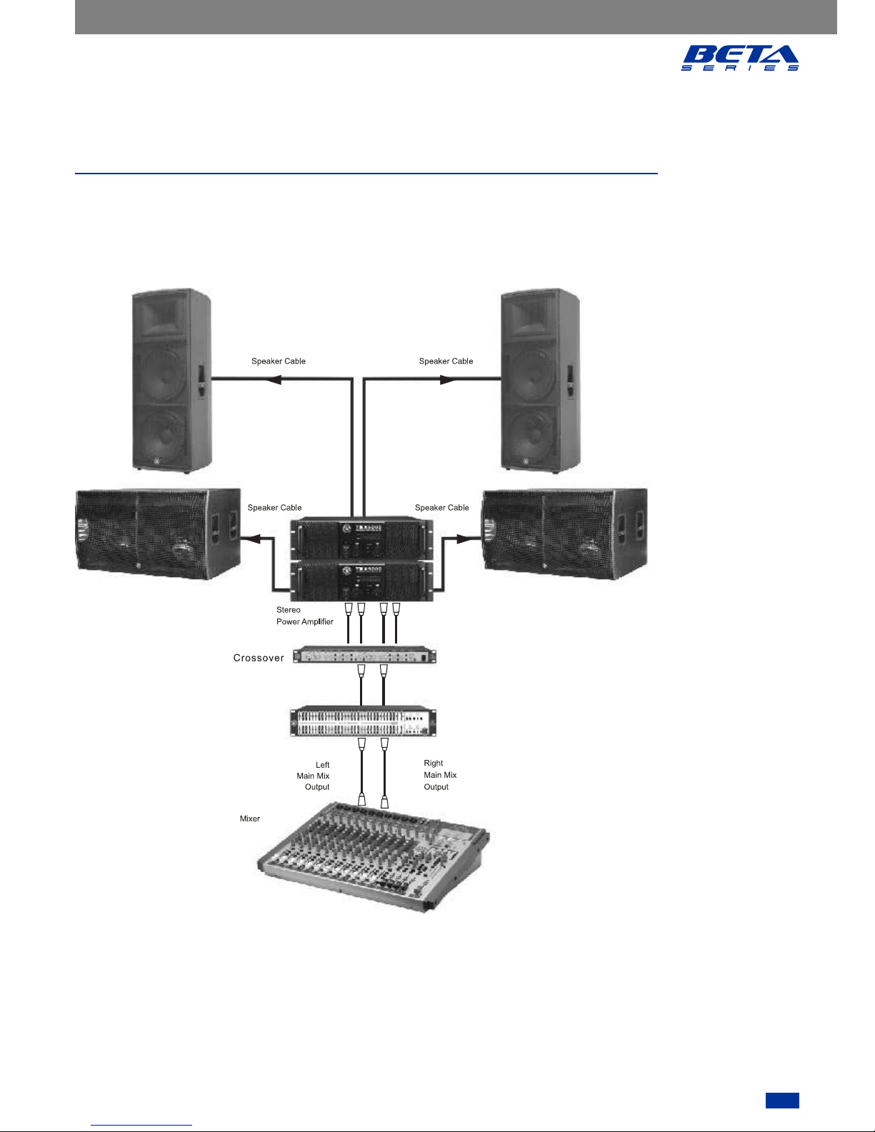
Connecting Diagram
Make your initial connections with all the equipment powered off, and ensure that all the main
volume controls are turned completely down.
For Passive Full-range Speaker Cabinet
1) Connect one side of the speaker cable to the Output CH A / CH B ot Binding Post of your stereo
power amplifier and the other side to the Input socket of your speaker cabinet.
2) Complete other connections as illustrated.
3) Turn on your mixer first, then the stereo power amplifier.
4) Turn up the volume controls of your amplifier to about 70%.
5) Use PFL function to get the proper input level for the mixer, and adjust the Main Mix Level control
to manipulate the output level.
6) After using, turn off your stereo power amplifier first, then the mixer.

5
Connecting Diagram
4
Make your initial connections with all the equipment powered off, and ensure that all the main
volume controls are turned completely down.
For Passive Full-range Speaker Cabinet
1) Connect one side of the speaker cable to the Output CH A / CH B ot Binding Post of your stereo
power amplifier and the other side to the Input socket of your speaker cabinet.
2) Complete other connections as illustrated.
3) Turn on your mixer first, then the stereo power amplifier.
4) Turn up the volume controls of your amplifier to about 70%.
5) Use PFL function to get the proper input level for the mixer, and adjust the Main Mix Level control
to manipulate the output level.
6) After using, turn off your stereo power amplifier first, then the mixer.
TOPP PRO
MUSIC GEAR
TPS BETA 1152 TPS BETA1152
FIG. 1
TPS BE TA 2152 TPS BE TA 2152

46
4
Connecting Diagram
TOPP PRO
MUSIC GEAR
For Passive Satellite Matching with passive Subwoofer Speakers
1) Connect one side of the speaker cable to the Output CH A / CH B ot Binding Post of your stereo
power amplifier and the other side to the Input socket of your subwoofer, do the same
connection on your second power amplifier and the 2-way full-range passive speakers with a
second speaker cable.
2) Complete other connections as illustrated.
3) Turn on your mixer first, then the stereo power amplifier.
4) Turn up the volume controls of your amplifier to about 70%.
5) Use PFL function to get the proper input level for the mixer, and adjust the Main Mix Level control
to manipulate the output level.
6) After using, turn off your stereo power amplifier first, then the mixer.
FIG. 3
Cros so ver
Equa li zer
TPS BETA15 SU B
TPS BETA1152
TPS BETA1152
TPS BETA15 SUB
Connecting Diagram
For Passive Subwoofer & 2-way full range Speakers
57
4
Connecting Diagram
TOPP PRO
MUSIC GEAR
For Passive Subwoofer & 2-way full range Speakers
FIG. 3
Equa li ze r
TPS BETA215 2
TPS BETA215 2
TPS BETA218 S UBTPS BETA218 S UB
 Loading...