

Topp Music Gear TMW-9144R, TMW-9144T, TMW-9144P User Manual
SEIKAKU TECHNICAL GROUP
LIMITED
A3
A4
A5
MAR.20.2006
TOPP PRO
/
TMW-9144R/T/P TOPP PRO_V1.0
0.18Kg/1
105g
PE02260
18
PGBSC001-20050900183,A,1
PHFWA102-20060200034,A,1
NF02448
TMW-9144R/T/P
R
TMW-9144P
User's Manual
WIRELESS MICROPHONE SYSTEM

SAFETY RELATED SYMBOLS
CAUTION
RISK OFELECTRIC SHOCK
DO NOTOPEN
This symbol, wherever used, alerts you to the presence of un-insulated and dangerous voltages within the product enclosure. These are voltages that
may be sufficient to constitute the risk of electric
shock or death.
Protective Ground Terminal
AC mains (Alternating Current)
Hazardous Live Terminal
ON: Denotes the product is turned on.
This symbol, wherever used, alerts you to important operating and maintenance instructions.
Please read.
OFF: Denotes the product is turned off.
WARNING
Describes precautions that should be observed to
prevent the possibility of death or injury to the user.
CAUTION
Describes precautions that should be observed to
prevent damage to the product.
Protective Ground
Operating Conditions
IMPORTANT SAFETY INSTRUCTIONS
Cleaning
Servicing
Power Cord and Plug
the recommended fuse type as indicated in this
manual. Do not short-circuit the fuse holder. Before
replacing the fuse, make sure that the product is
OFF and disconnected from the AC outlet.
Before turning the product ON, make sure that it is
connected to Ground. This is to prevent the risk of
electric shock.
Never cut internal or external Ground wires. Likewise,
never remove Ground wiring from the Protective
Ground Terminal.
Always install in accordance with the manufacturer's
instructions.
To avoid the risk of electric shock and damage, do
not subject this product to any liquid/rain or moisture.
Do not use this product when in close proximity to
water.
Do not install this product near any direct heat source.
Do not block areas of ventilation. Failure to do so
could result in fire.
Keep product away from naked flames.
Read these instructions
Follow all instructions
Keep these instructions. Do not discard.
Heed all warnings.
Only use attachments/accessories specified by the
manufacturer.
Do not tamper with the power cord or plug. These are
designed for your safety.
Do not remove Ground connections!
If the plug does not fit your AC outlet seek advice from
a qualified electrician.
Protect the power cord and plug from any physical
stress to avoid risk of electric shock.
Do not place heavy objects on the power cord. This
could cause electric shock or fire.
When required, either blow off dust from the product
or use a dry cloth.
Do not use any solvents such as Benzol or Alcohol.
For safety, keep product clean and free from dust.
Refer all servicing to qualified service personnel only.
Do not perform any servicing other than those instructions contained within the User's Manual.
Fuse
To prevent fire and damage to the product, use only
No user serviceable parts inside.
Power Supply
Ensure that the mains source voltage (AC outlet)
matches the voltage rating of the product. Failure
to do so could result in damage to the product and
possibly the user.
Unplug the product before electrical storms occur
and when unused for long periods of time to reduce
the risk of electric shock or fire.
External Connection
Always use proper ready-made insulated mains
cabling (power cord). Failure to do so could result
in shock/death or fire. If in doubt, seek advice from
a registered electrician.
Do Not Remove Any Covers
Within the product are areas where high voltages
may present. To reduce the risk of electric shock do
not remove any covers unless the AC mains power
cord is removed.
Covers should be removed by qualified service
personnel only.
WARNING
Disposing of this product should not be
placed in municipal waste and should be
Separate collection.
ENGLISH
1

TABLE OF CONTENTS
1. .. .
2. ...... ......... . ........... .......................................4
3. .... . .. .... .5
4. ... .. ... ... . ......................................8
5.
INTRODUCTION
FEATURES
CONTROL ELEMENTS
OPERATION
TECHNICAL SPECIFICATIONS
ANNEX
. ............................................................................................................................................3
.... . ..................... ............................................................
........ . ............................................................................................................... .
... .. .. ... ..........................................................................................
......................................................................................................................12
6. ..............................................................................................................................................................13
2
1. INTRODUCTION
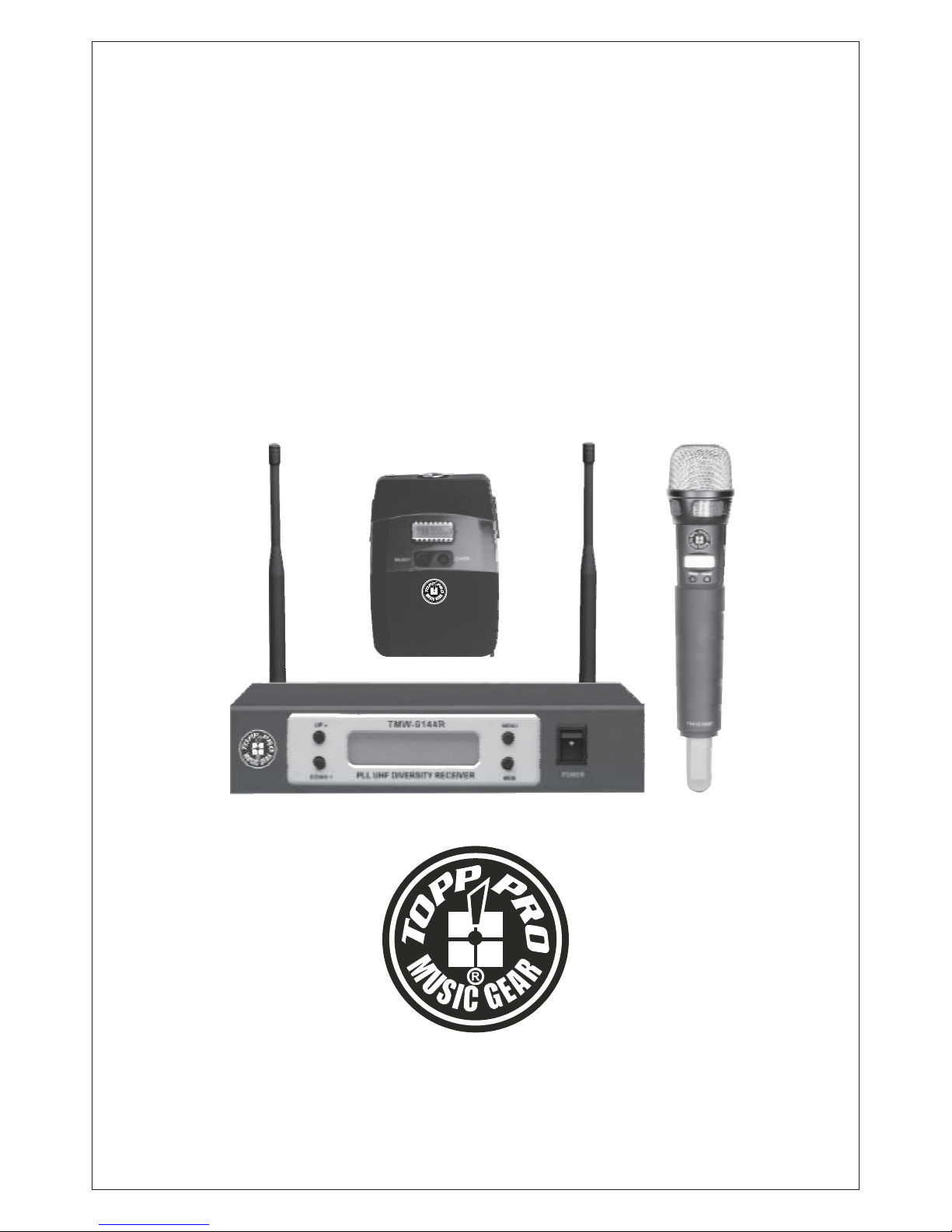
Thanks for purchasing the TOPP PRO wireless microphone system. The TMW-9144R/T/P series is delicately designed
UHF, PLL synthesized system, with two antennas built inside the receiver for smart switching diversity control, the higher
level RF signals may be fed into the system for greater reliability and coverage, therefore, the risks of breakdown and
interference are effectively reduced.
By the Auto Scan function provided by the TMW-9144, PLL UHF Diversity Receiver, the operating frequency of the
transmitter may be automatically searched out and locked by the system. Or, you can manually adjust the channel
of the transmitter to match the receiver in case you know the operating frequency of it.
Generally, the TMW-9144R/T/P series consists of
TMW-9144R, PLL UHF Diversity Receiver.
TMW-9144T, Handheld transmitter.
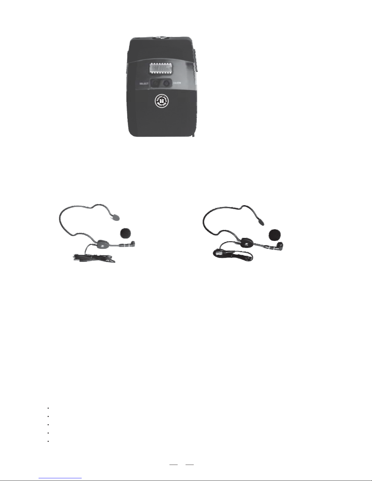
TMW-9144P series, Body Pack transmitter.
TMW-9144R, PLL UHF Diversity Receiver
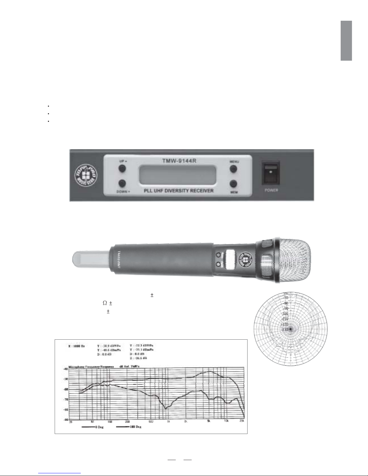
TMW-9144T, Handheld transmitter
Type: Dynamic Mic.
Frequency response: 50Hz~16kHz( 3dB)
Impedance: 300 20% at 1kHz
Sensitivity: -71dB 3dB
Direction: Omni-directional
30
60
90
120
330
300
270
240
210
180
150
3
ENGLISH
R
TMW-9144P
TMW-9144P series, Body Pack transmitter
For the TMW-9144P series, there are several types of clip microphone are please make
sure that the proper microphone has been sound reinforcement system before installation.
included in this product range,
selected for your typical
HM-38, Condenser microphone
Preset impedance: 600ohm;
Freq. response: 80-12KHz;
Sensitivity: -68dB+/-3dB at 1KHz;
Directional: Uni-directional;
Weight: 52g (0.12Ib)
HM-58, Condenser microphone
Preset impedance: 700ohm;
Freq. response: 200-8KHz;
Sensitivity: -65dB at 1KHz;
Directional: Uni-directional;
Weight: 54g (0.12Ib)
Last but not the least, the operating frequency of this wireless system may be varied from 470MHz to900MHz, please refer
to your national EMC regulations to pick out the authorized frequency band (F1 ~ F8, detail please see Annex hereafter) for
your application.
2. FEATURES
TMW-9144R, PLL UHF Diversity Receiver
Friendly interface of front panel LCD status display.
Auto Scan function for easy and convenient operation.
Switching diversity control to receive the RF signal.
Three output levels.
Squelch control.
4
3. CONTROL ELEMENTS
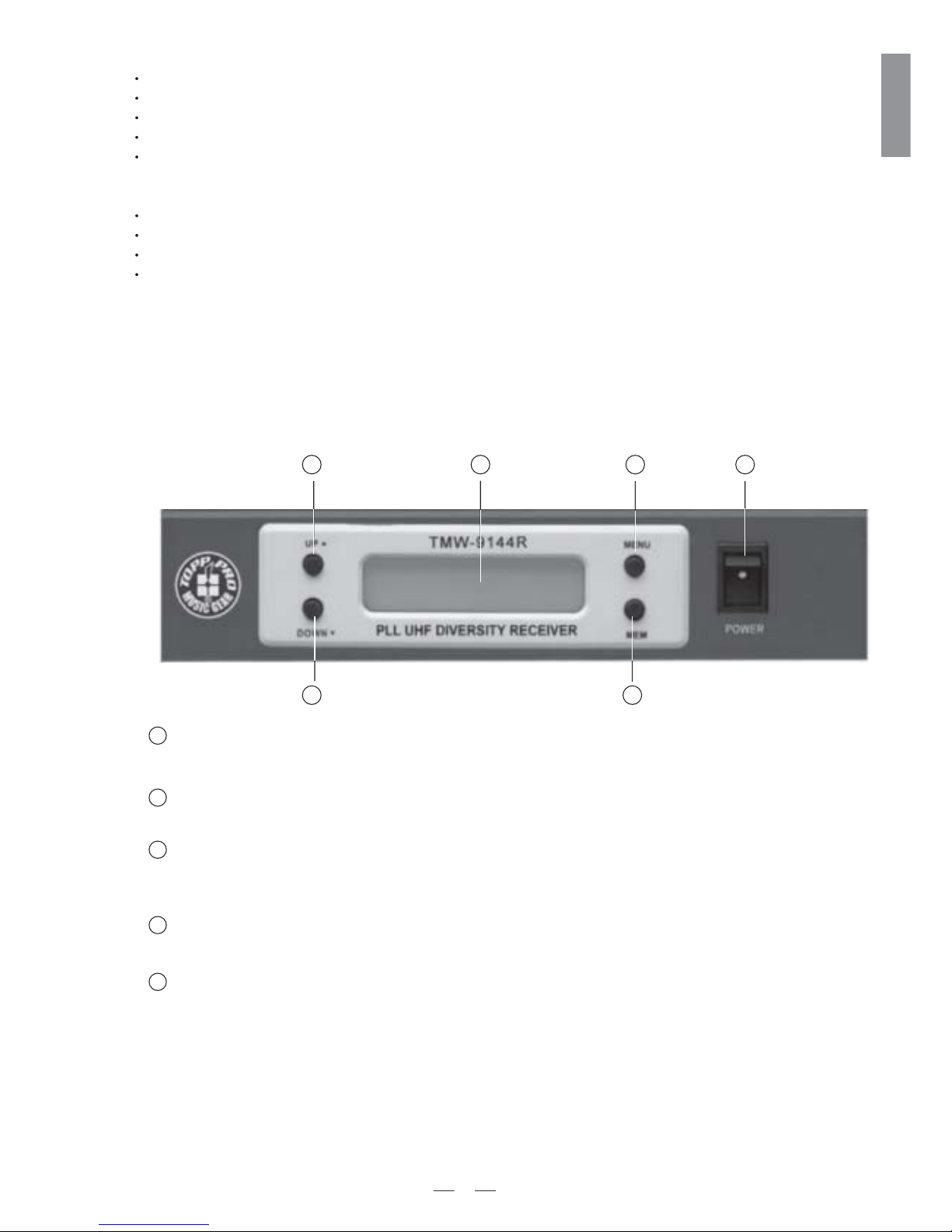
3.1 TMW-9144R, PLL UHF Diversity Receiver
THE FRONT PANEL
Power Switch
It switches on/off TMW-9144R main power.
1
Via this key, you can choose the function you want.
In the menu mode, you can choose the right value via these two keys.
The LCD shows RF/AF signal, remaining battery life of the transmitter, group value, channel value
and the selected frequency.
UP/DOWN key
2
Display
3
Menu key
4
It is equipped with two functions, memo function, and auto scan function.
MEM key
5
Soft touch painting for comfortable use.
Rechargeable battery design.
Three RF output power levels.
Mute function.
Lock function to avoid the misaction during live applications.
Common features
PLL synthesized design.
Consistent operating frequencies to comply with EMC regulations.
Up to 12x12, total 144 channel frequency presets.
Manufactured under ISO9000:2000, ISO/TS16949:2002 quality management system.
TMW-9144T/P transmitters
3 4 1
2
2 5
5
ENGLISH
Antenna Input Socket
Allows you to connect plug-in antennas, remote antennas, or even a complexantenna network.
XLR Audio Output
This is a professional balanced XLR output connector.
Audio Output Jack
This is a professional unbalanced output jack.
It is used to connect an attached adapter.
DC Input
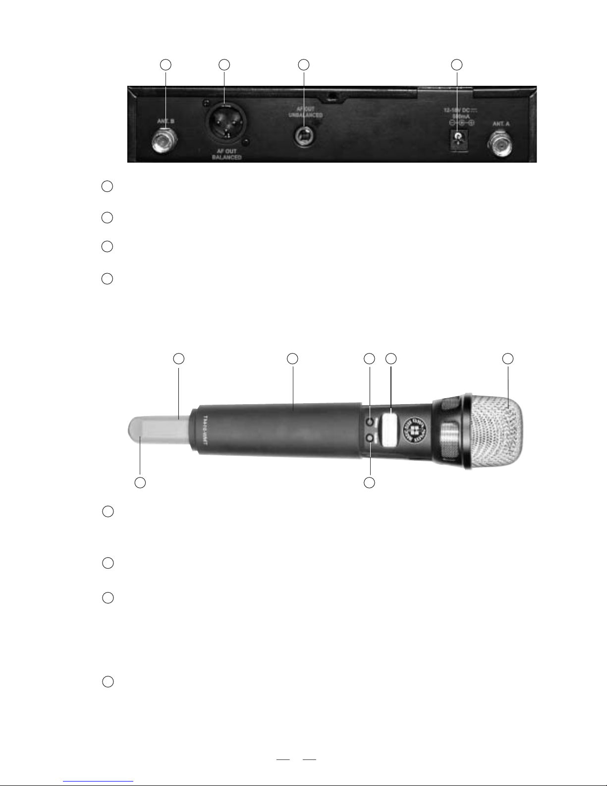
3.2 TMW-9144T, Handheld Transmitter
Extremely rugged spring steel mesh grill to protect the capsule underneath in tough stage or live
performances.
Massive Front Grill
Generally, the LCD displays the current operation status.
Keep pressing this key for a few seconds, the unit is powered on or off. After it is switched on,
touch this key slightly to select the parameter which you want to edit,such as the preset channel,
preset group, PL (RF power level), and Lock/unlock; In this mode, if there is no further operation
in the next few seconds, it will return to the main menu, and the LCD displays again the current
preset frequency in MHz, as well as the battery status.
LCD Display
CH/ON Key
THE REAR PANEL
1 2 3 4
1
2456
37
1
2
3
4
1
2
3
Use this key to edit the parameters in operation mode. Keep pressing this key for a few seconds, the
unit enters into the mute mode, repeat for unmute.
SELECT Key
4
6
R
TMW-9144P
Connect the optional recharger(see fig) with this mini jack for battery recharging.
Please make sure that it has rechargeable batteries inside before plugging in the
recharger with the mini charge jack.
Charge Jack
6
The antenna is integrated into the transmitter body; to get effective RF transmission, never cover the antenna
with hand, etc.
Antenna
7
3
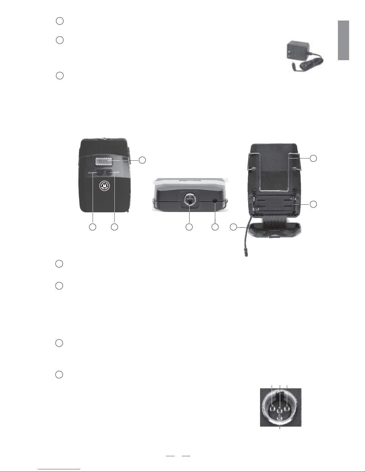
3.3 TMW-9144P series, Body Pack Transmitter
CH/ON Key
Keep pressing this key for a few seconds, the unit will be powered on or off. After it is switched on, touch this
key slightly to select the parameter which you want to edit, such as the preset channel, preset group, PL(RF
power level) and Lock/unlock. In this mode, if there is no further operation in the next few seconds, it will
return to the main menu, and the LCD displays again the current preset frequency in MHz, as well as the
battery status.
SELECT Key
Use this key to edit the parameters in operation mode. Keep pressing this key for a few seconds, the unit will
enter into the mute mode, repeat for unmute.
2
3
1
LCD Display
Generally, the LCD displays the current operation status.
4
Mini 4P connector
This connector is used to connect the unit with the clip microphones,
for example, HM-38 or HM-58 condenser microphones.
The unit may be powered from a dry or rechargeable battery.
Battery Compartment
5
2
1
4
5
7
6
8
314
2
Pin 2, GND
Pin 4, for Dynamic or condenser microphone
7
ENGLISH
Pin 3, Phantom power supply for Condenser microphone
Pin 1, for Guitar, bass and keyboards

Antenna
It is a flexible antenna. To get effective transmission, never cover the antenna hand, clothes, etc during
operation, and always position the transmitter receiver.
with
nearby the
8
Charge Jack
With the rechargeable batteries inside, use the charger (optional accessory, provided by the manufacturer)
to recharge the batteries. For detail operation, please refer to chapter 4.2.3, Battery replacing and charging.
5
Battery Compartment
This unit may be powered from one pair of dry or rechargeable batteries, UM3 size AA 1.5V.
6
Belt clip
It is the detachable belt clip for easy carry during live applications.
7
4. OPERATION
ABCDE
F
G
Fig 1
A: Frequency group.
B: Subchannel.
C: Mute(if the mute function is engaged, the mute label is shown, if not , the label disappears).
D: The selected frequency.
E: Remaining battery life of transmitter.
F: Audio bar graph indicating the receiver audio level.
G: RF bar graph indicating the field strength of the received signal.
4.1 For the TMW-9144R, PLL UHF Diversity Receiver
Auto Scan
When the receiver is powered on, press and hold the MEM key for one second, receiver is in auto scanning.the
The scan function automatically searches the frequency band from start to stop. During the search,receiver's entire
the indicates the frequencies in MHz as they areaudio output is muted and the display scanned. As soon as the
correct frequency is reached, , the value of frequency will be flashing, pressthe scan will be stopped automatically
the MEM key, the information.you can save
Remark: some frequencies should be scanned manually by adjusting UP/DOWN pleasekey, refer to Annex
for details!
Manually Selecting Frequency
Press the MENU button, "GROUP" is flashing, you can choose the right frequency you need via the UP/ DOWNgroup
button, when the frequency group is set, please MEM button to store the information. Press the MENU button twopress
times, is flashing, you can choose the right subchannel you need via the when the"CHANNEL" UP/DOWN button,
subchannel you need is set, please press the MEM button to save it.
8
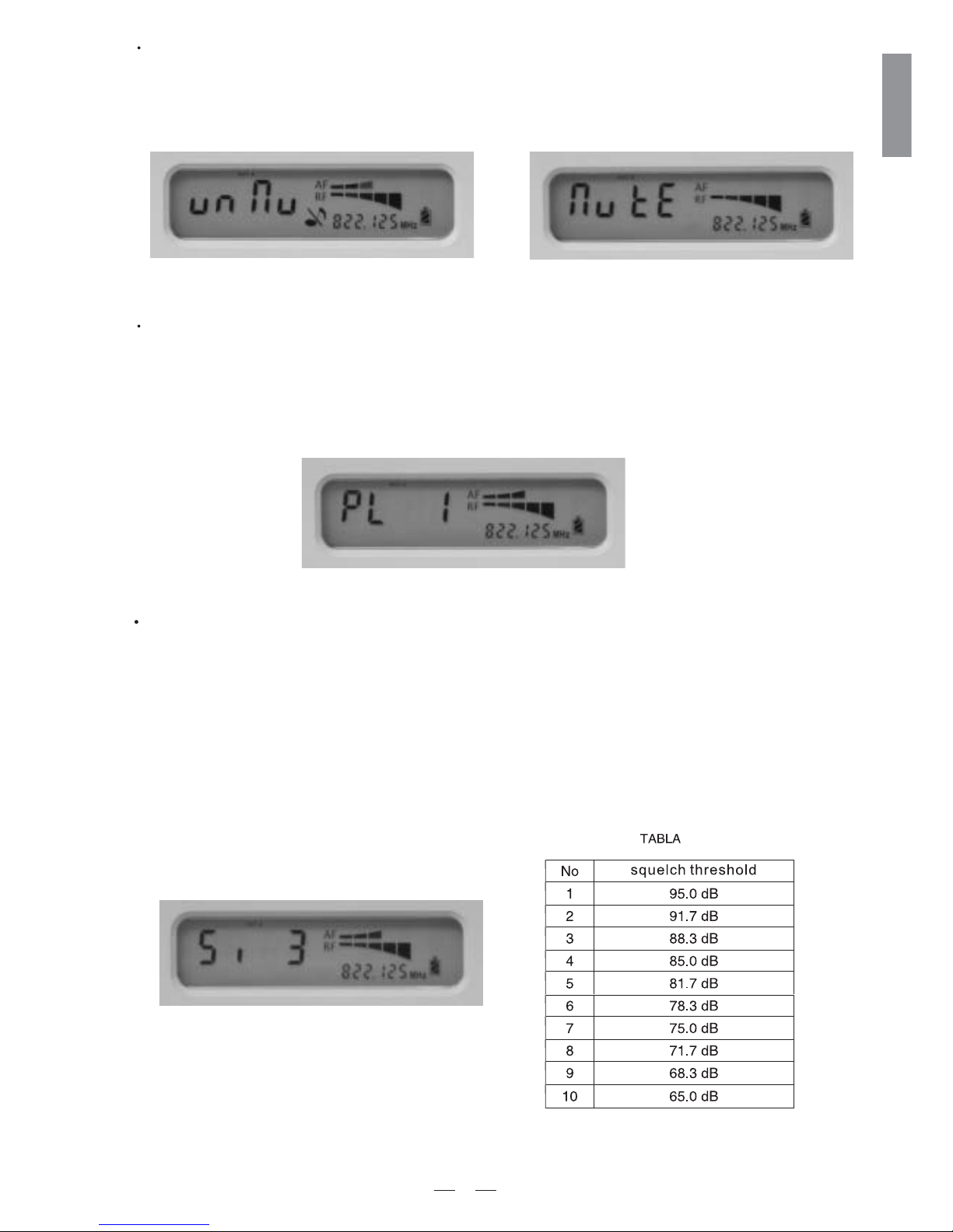
Fig 3 mute function onFig 2 mute function off
Output Level Adjusting
In output level adjusting mode(see fig 4), use the SELECT button to adjust the output level. The output level
has 3 choices, 0 indicates the output level is 500mV, 1 indicates the output level is 300mV, 2 indicates the
output level is 150mV.
Fig 4
Note: the function is only applied to the level of Balanced output.
Squelch Control
Fig 5
Mute Function
In mute mode, use UP/DOWN key to on/off the mute function.(fig 2 mute function off, fig 3: mute function on),:
press the MEM button to keep the information. Note: when the transmitter is muted, no audio signal will be sent
out from the receiver.
9
ENGLISH
The job of a squelch circuit is to reduce audible noise. It eliminates noise during pauses in the audio signal by
muting the receiver every time the audio level drops below a defined threshold. The squelch control on the receiver
sets this threshold. Use the squelch control with care! If the squelch threshold is too high, the squelch will not only
cut out noise but mute quiet audio signals as well because the squelch responds to the detected voltage and cannot
distinguish between wanted signal and noise. Besides that, a too high squelch threshold also decreases the usable
range. In the squelch control mode(fig 5), use the UP/DOWN key to select squelch threshold. In order to achieve
easy operation, the squelch threshold is divided into10 levels,please refer to table.
4.2 For the TMW-9144T/P series transmitters,
4.2.1 Edit The Parameter
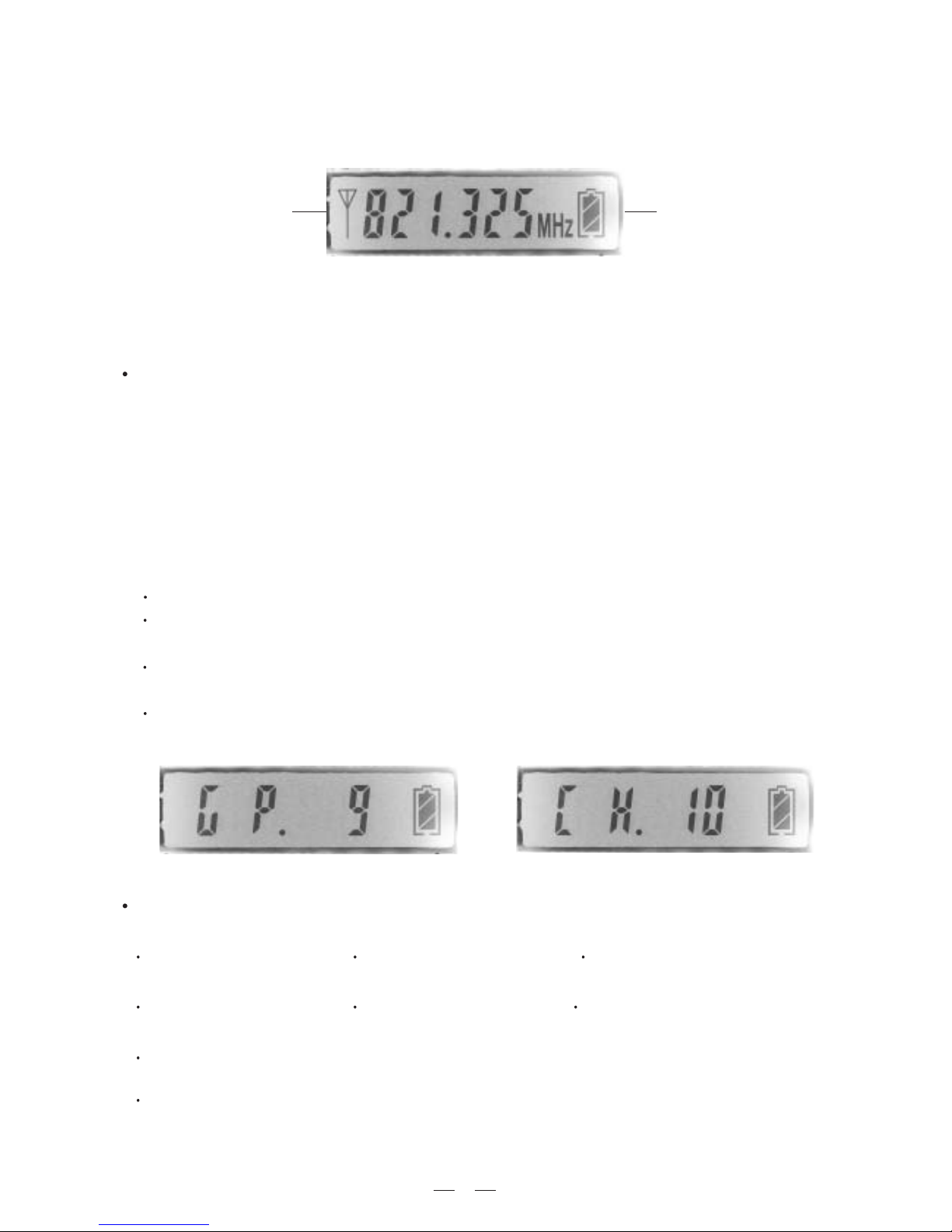
Press and hold the CH/ON key for a few seconds, then the transmitter is powered on. Now, the LCD displays the
current operation status:
Fig 6
Preset frequency Remaining battery life
Fig 7
Fig 8
Frequency select
It is a multi-channels PLL synthesized system. In practice, to effectively avoid the interference from
any lighting equipment, computers, fax machines, etc nearby, it is usually advised to switch to another frequency
to get best performance.
After the transmitter is switched on, touch the CH/ON key slightly to select the parameter which you want to
edit, such as the preset channel, preset group, PL (RF power level), and Lock/unlock.
The frequency range of this system is UHF, 470MHz ~ 900MHz, and it is divided into 8 frequency bands (F1 ~ F8)
according to the country's EMC regulations; For each frequency band, to select the proper frequency preset, please
first pick the right Group, then the Channel; For details please refer to the Annex.specify
For example, in F7 frequency band, if you want to select the frequency preset of 811.125MHz (Group 6, Channel 6),
please follow the below procedure.
Touch the CH/ON key slightly again to select the edited parameter of Group (refer to Fig 7), then use the SELECT
key to specify the proper Group.
Several seconds later after that, the system stores the settings automatically, and LCD display comes back to
the main menu which shows the current operation status.
Turn on the unit first.
Touch the CH/ON key slightly to select the edited parameter of Channel (refer to Fig 8), then use the SELECT
key to specify the proper channel.
RF Output Power Select
Three different RF output power levels are available of TMW-9144T
PL 0, the output power is 5dBm; PL 1, the output power is 10dBm; PL 2, the output power is 15dBm.
But, It's a different from TMW-9144P
PL 0, the output power is 3dBm; PL 1, the output power is 5dBm; PL 2, the output power is 12dBm.
Please follow the below procedure to select the proper RF output power
Touch the CH/ON key slightly to select the edited parameter of PL (refer to Fig 9), then use the SELECT key to specify
the proper RF output Power version.
Several seconds later after that, the system stores the settings automatically, and LCD display comes back to the main
menu which shows the current operation status.
10
 Loading...