

Page 1
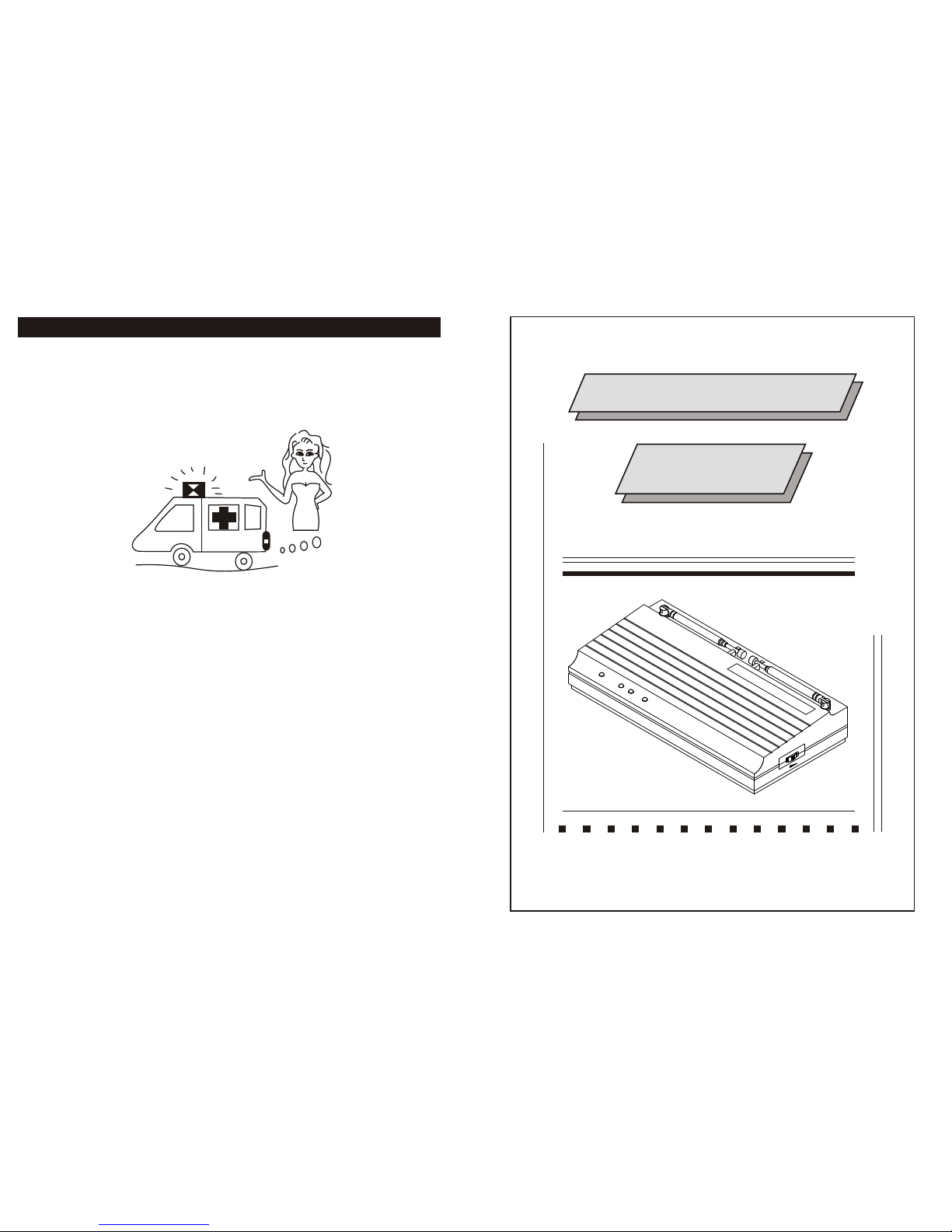
WIRELESS SYSTEM
INSTRUCTION
MANUAL
VOLU
M
E
ON
OF
F
WIRELESS
MIC
. R
E
C
E
IV
ER
PO
W
ER
ON
DIVERS
IT
Y
A-
---
---
--B
AU
DIO
PE
AK
IF YOU ARE NOT TECHNICAL
ENGINEER PLS. DO NOT
MODIFIED OR KNOCK - DOWN
IT.
NOTE
NF03533-1.0
Page 2
Specifications :
Character :
antenna.
LED Indicator (Power , Diversity (A---B) , Peak ) and telescopic
Compact, lightweight,single channel receiver.
from 160-245 MHz
VHF High band frequency by quartz locked controlled. Range
Compression / Expanded circuit for extended dynamic range.
Special circuit design to delete microphone switch ON/OFF noise.
Weight
Dimensions
Power supply
Output connector
Audio output level
( Receiver sensitivity )
Squelch
Receiving mode
Frequency response
S/N Ratio
Dynamic
T.H.D.
Max. deviation
Modulation mode
Frequency stability
Carrier frequency range
Receiving method
With AC/DC adaptor 115/230V 50/60Hz
298.5g
202 98 34 mm
DC 12V ~ 18V 300mA
Unbalance 6.3 mm phone jack
At deviation = 40KHz
Unbalance ,300mV , 10KW load
-65dBm ~ -90dBm Adjust
Noise control Normal=-85dBm
Quartz control fixed frequency
50Hz-15KHz 3dB
>90dB
>100dB
<1%
40KHz,,with limiting compress
FM (F3E)
0.005% /25 C
VHF Hi-Band 160-245MHz
Diversity receiver
1
6
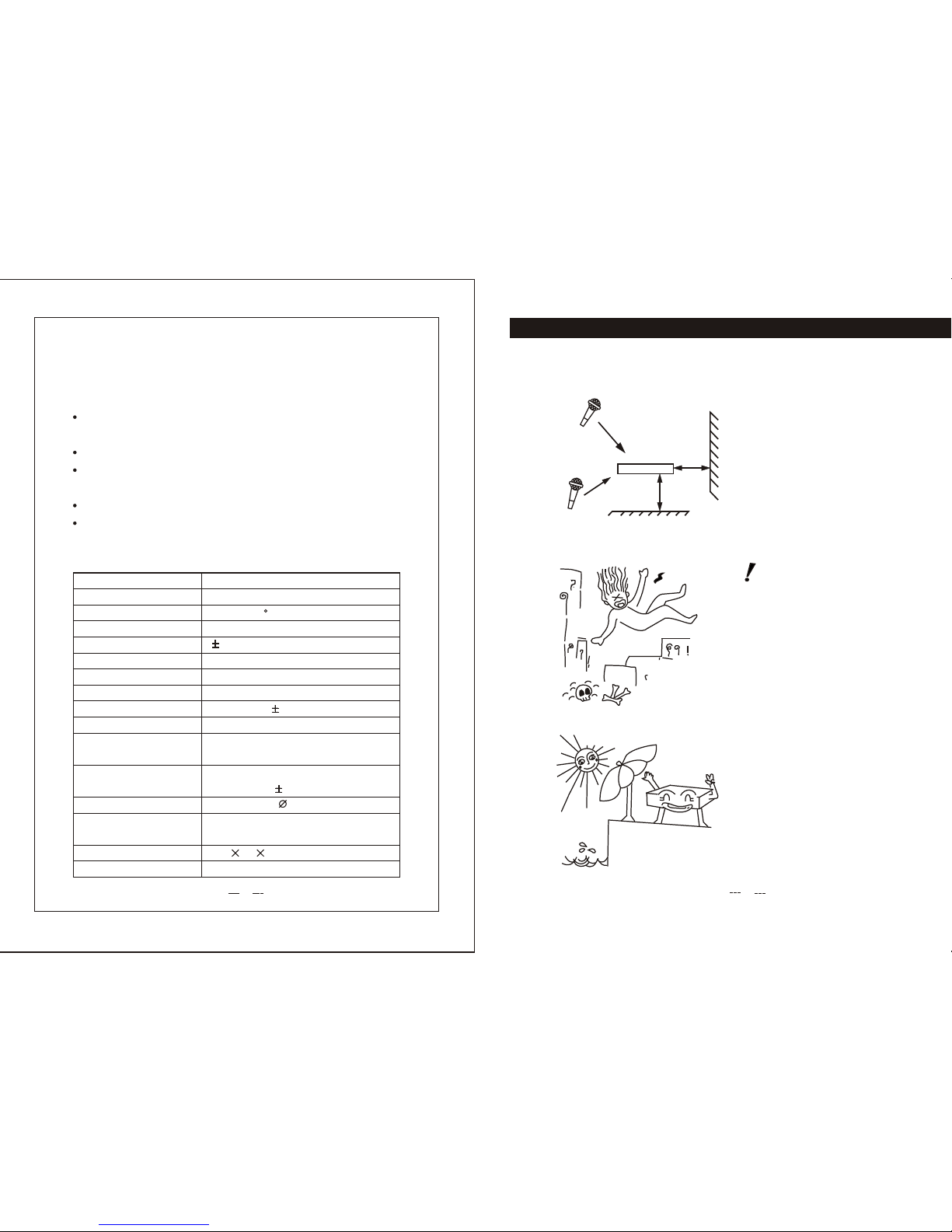
KEEP AWAY RAINING OR
SUN SHINE.
BE CAREFUL, DON'T DROP
OFF THE MICROPHONE TO
FLOOR
THE WIRELESS RECEIVER
LOCATED AT GOOD CONDITION
PLACE.
NOTE
1m
1m
4
0-
6
0
m
RECEPTEUR
RECEPTEUR
1m
HELPHELP
Page 3

NAMES OF PARTS
7. Power Input Connect
6. Audio Output Connector
5. Telescopic Antenna.
4. Power Switch / Volume Control
3. Audio Peak Indicator
2. Mic. ON and Diversity Signal Indicators
1. Power ON Indicator
2
5.
4.
1.
2.
3.
VO
LU
M
E
ON
O
FF
W
IR
E
LES
S
MIC.
R
E
C
E
IVER
PO
W
ER
O
N
DIVE
RSITY
A----
---
----B
AU
DIO
PEAK
DC IN
6.
AUDI
O
OU
T
7.
5
ON
POW
ER
AUDIO
A-----------
B
DIVERSIT
Y
PEAK
W
IRE
L
ESS M
IC
. REC
EIV
E
R
SERIAL
NO.
FREQUEN
CY
N
o.
R 00
026
1
1
94.82
0 Mhz
DC 12V 300
m
A
S
QUELCH
MAX
SENS
.
6. Squelch Control
This control is factory present,
SQ noisy controlled adjustment,
Before you turn-on the transmitter,
Please turn-on the receiver at first. The
receiver already have been jamming by outside
signal. Please adjust SQ control until the jamming
signal has disappeared. (clock-wise)
a. Power ON Indicator:
This red light glows when the
DC supply and power Switch
ON. It indicates that the rece-
iver is on.
b. Reception Indicator:
This indicator does light during
standby. When microphone
signal is received, The green or yellow indicator
light to indicate the reception of microphone.
c. Audio peak Indicator: This red light flickers when the audio
signal from the microphone approaches the overload clipping level.
It is affected by the transmitter gain control setting and the loudness
of your voice.
5. Indicator.
FIG.5
(SQ JUST)
INSTRUCTION MANUAL
Page 4

3
1. Install Antenna
Receivers signals from the transmitter.
Make sure the antenna is fully extended
vertically.
INSTRUCTION MANUAL
2. Audio Output Connector
You can connect an unbalanced
audio cable with a 1/4 inch phone
plug between this connector and
your mixer or amplifier input.
FIG.1
FIG.2
45
45
UN
B
AL
IN
M
IC / AUX IN
PUT
AUD
IO O
UT
DC
IN
4
3. Power Supply Connection
Use DC power supply could switch with
adaptor supply or batter of 12-18V DC.
Connection DC supply , DC plug conn ection with "DC-IN" socket. (See FIG.3)
another plug terminal connection with
battery or power supply.
4. Bouton de Puissance/controle
de Volumen
Tournez le bouton de controle de
marche/arret et augmentez ou
diminuez le volume de debit de
recepteur. Le controle a un effet
sur l'indicateur de pointe sonore.
FIG.3
INSTRUCTION MANUAL
1
2V-18V
DC
IN
AUDIO
OU
T
DC
IN
VOLU
ME
ON
OF
F
FIG.4
 Loading...