

Topp Music Gear Soho FLX series, FLX 3, FLX 5, SOHO S12 FLX User Manual
FLX 3 / FLX 5 / SOHO S12 FLX
SOHO FLX
1. Introduction
2. Installation Tips
3. Usefull Data
4. Quick Start
5. Satellite Layout of The Connector Panel
6. Satellite Back Panel Description
7. Satellite Down Connection
8. Satellite Up Connection
9. Subwoofer Back Panel Description
10. Technical Specifications
11. System Connection Plate
12. Wire Connections
13. Guarantee
14. Notes
4
4
4
5
6
8
11
12
13
14
16
19
20
21
3
Introduction
Thank you for choosing TOPP PRO. The new TOPP PRO ARRAY SERIES cabinets have been
designed to provide a cost effective high grade solution while maintainig high quality cabinet
construction and optimum components.
The array series, can be used for all types of applications including, but not limited to, churches,
conference centers and discos.
The woofer and neodymium driver combination provides excellent performance rivaling those
cabinets costing much more.
Speakers should be placed in a position that allows for unobstructed sound projection. In many
instances it is beneficial for speakers to elevate on tripod stands to achieve maximum dispersion
and reach. Consider TOPP PRO speaker stand or equivalent to raise speakers.
Using quality cables ensure best possible sound. Consider using TOPP PRO 16 or 14 gauge
cables or equivalent.
For best results match the speakers to a good amplifier that matches the wattage and
impedance of your speakers. Proper amplification power results in good quality audio and
longer component life. Check out.
Avoid pointing microphone directly at an amplified speaker otherwise could cause feedback
possible damaging speaker components and your hearing.
Our Professional Audio Products are designed and tested by a highly qualified engineering team
with more than 20 years of experience. Great care is placed in delivering products with excellent
performance, specifications and dependable reliability. Also great emphasis is placed in creating
and bringing to market products that can fill multiple applications and also offer customers
exceptional value.
Installation Tips
Usefull Data
Please write your serial number here for future reference.
4
4
Wall bracket
Satellite
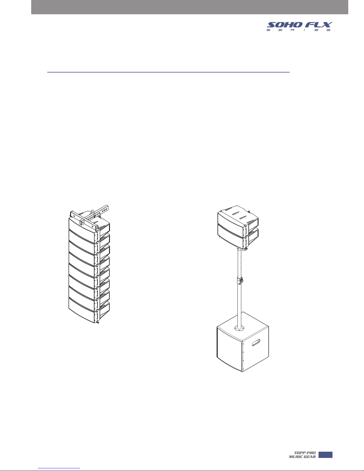
Quick Start
When mounting a speaker onto any stand, always ensure that the stand is on a flat, level
sur-face, with the legs fully extended. Be sure to check that the maximum load weight for the
stands is greater than the weight of the ARRAY SYSTEMS loudspeaker. Never use a stand with a
maximum load weight lower than the speaker. Do not attempt to mout more than one speaker
on a stand at one time.
The ARRAY SYSTEMS loudspeakers are heavy. It is recommended that a second person to help
place the cabinet on a stand.
When the speaker is placed on a stand, always check the integrity and center of gravity of the
system If the speaker can be tipped easily, or the pole is swaying, it is recommended that you
lower the height of the stand. Position the stand and route cables so that the performers and the
audience cannot tip over or trip on the system.
Subwoofer
Pole
Satellite
5
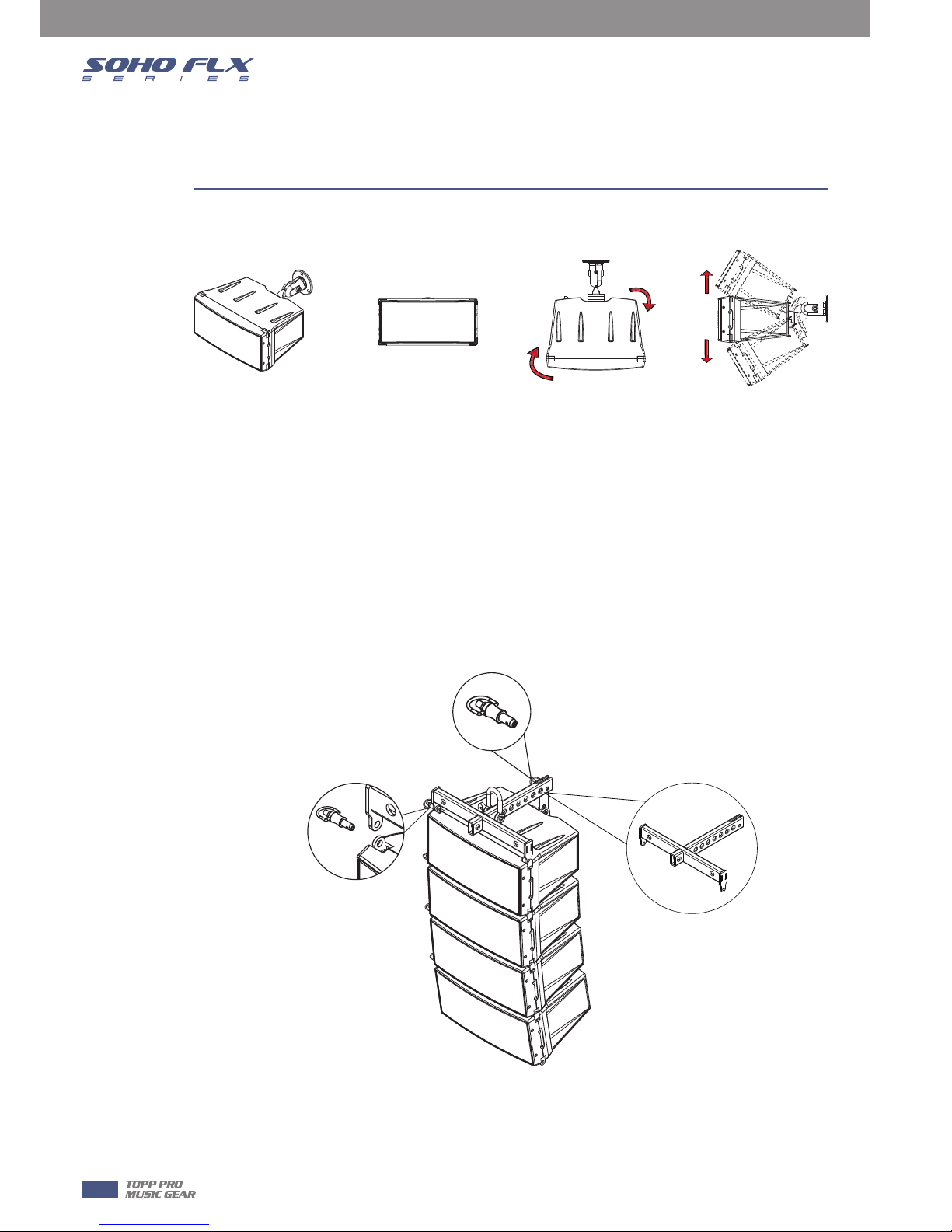
Satellite Layout of The Connector Panel
More module
Versatile mounting options
Compared to many other speaker designs, the satellite Series is remarkably easy to install in
several ways. It can be hung easily with chains, strong wires and cables using the accessory
brackets.
There are also options for hanging with a pre-install rame by itself or configured with a
subwoofer.
There are also other options including ceiling and wall brackets as well as an adapter for use with
a dedicated stand.
One module
The direction of the bracket can be adjusted from any side.
The bracket support wall and leiling mounting with most 8 modules .
The direction and angle can be adjusted from any side.
5
6
5
7
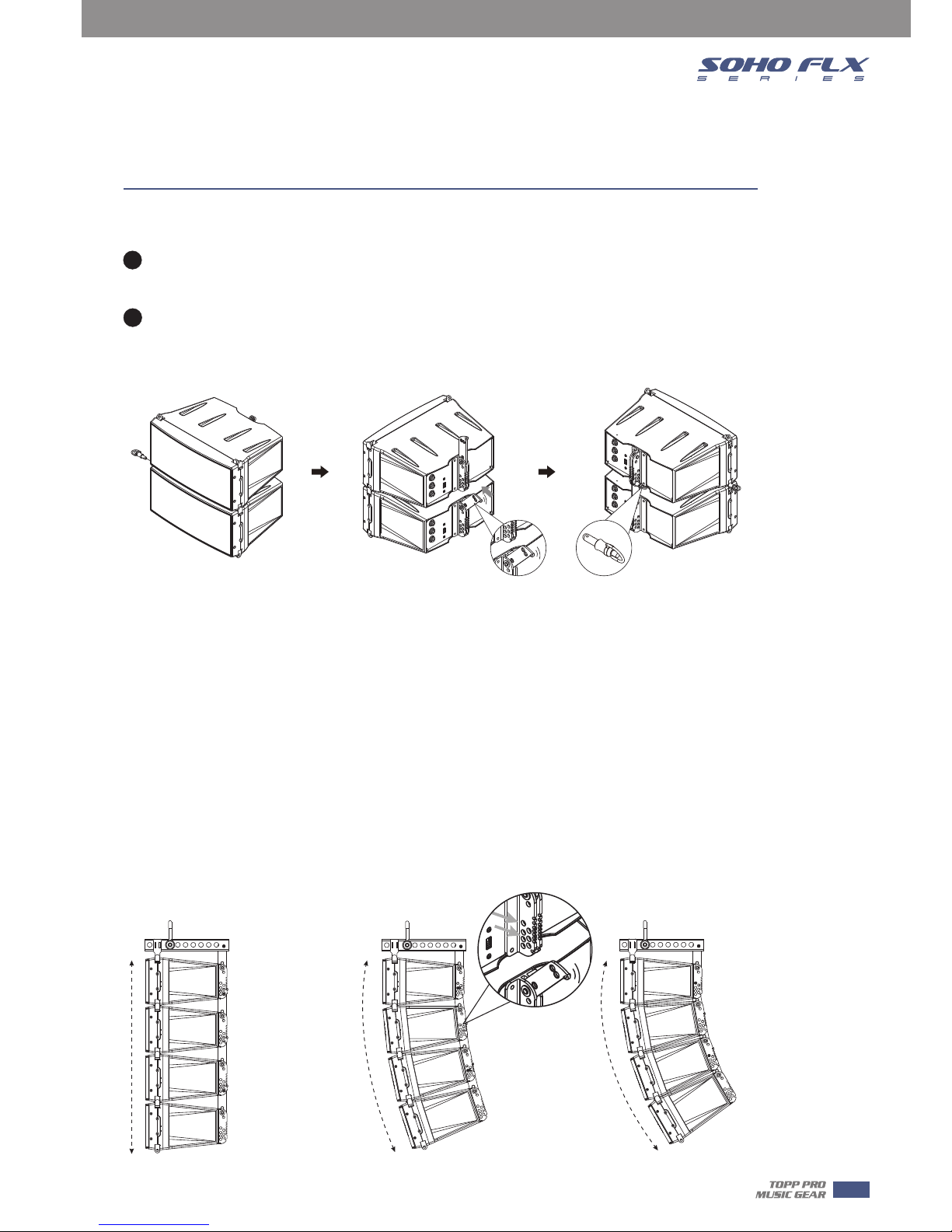
Satellite Layout of The Connector Panel
You can insert each three different holes when connecting the rear bracket. You can obtain
different sound by different angles.
Align two units to make the latch hole in the same line. Insert the latch and lock the screw
tightly.
Adjust the angles of the unit (seven angles: 0° -1.5° -3.0° -4.5° -6.0° -8.0° -10° for FLX 3,nine
angles: 0° -1.5° -3.0° -4.5° -6.0° -7.5° -9.0° -10.5° -12° for FLX 5 can be adjusted), insert the rear
connecting pin into the related slot and put the latch into the hole.
Connect Manner
1
2
Adjustable sound dispersion(for example four pcs)
A system in configured by vertically stacking four speaker modules with a total driver
complement of four woofers and 12 tweeters(four tweeters of FLX 5) positioned along the baffle
surface, this configuration allows the variable directivity control and low-frequency dispersion
control comparable to using a large constant-directivity horn speaker. A choice of seven angles
for FLX 3 / nine angles for FLX 5 can be employed as needed.
For instance, a specific directivity angle, or each module can have its directivity independently set
for a specific coverage requirement. When two or multiple modules are connected to configure
an arc, they effectively function as an immense single speaker controlling directivity for
considerably lower frequencies. As a result, public address functions demonstrate optimal
intelligibility even in environments with long reverb times.
directivity
max angle 40 for FLX 3
max angle 48 for FLX 5
 Loading...