

Topp Music Gear MXi.1222CFX, MXi.1422CFX, MXi.1622CFX User Manual

12 / 14 / 16 CHANNELS MIXING CONSOLE
3
Table of Contents
1. Introduction
2. Features
3. Usefull Data
4. Control Elements
5. Installation And Connection
6. Hookup Diagram
7. Preset List
8. Block Diagram
9. Technical Specifications
10. Guarantee
4
4
4
5
12
15
16
17
18
20
Introduction
Thank you choosing for purchasing 12 / 14 / 16 Channel Mixing Console. This is a professional
compact mixer to give you great quality and better reliability than ever before you will get the
smooth, accurate more natural and open sound from this apparatus, and it is really ideal for gigs
,recording and fixed PA installations.
The 12 / 14 / 16 channel Mixing Console is packed with features that can not be found in other
consoles of its size: 4 / 6 / 8 mono which can provided with ultra low noise microphone pre
amplifiers and Phantom Power at +48 Volt; 4 stereo input channels; 3-band EQ with
sweepable MID on mono inputs;4-band EQ on stereo inputs, 4 auxiliary control, highly accurate
12-segment bar graph meters and 2-track inputs assignable to main mix ,control room/phone
output etc...
This unit is very easy to operate but we advise you to go through each section of this manual
carefully. In this way you will get the best out of your Mixing Console.
Features
Usefull Data
Please write your serial number here for future reference.
4
• Ultra-low noise discrete MIC Preamps with +48V Phantom Power.
• 4 / 6 / 8 MIC Input Channels with XLRs and balanced Line Inputs.
• 4 / 6 /8 Compressors control and 6 / 8 Insert I/O.
• Low Cut for each MIC Input.
• 2 Stereo Input Channels with mono XLRs Input and TRS Jacks;
2 Stereo Input Channels with RCA Jacks.
• 3-band EQ with sweepable MID and Peak LEDs on each Mono channels. 4-band EQ and
Peak LEDs on Stereo channels.
• AUX 1 & AUX 2 Send POST/PRE per channel for monitoring or external effects.
AUX 3 & DFX Send POST Fader for internal effects or monitoring.
• PFL/Mute function for each channels, 60mm Fader for level control.
• GR1/2, GR3/4 and Main L-R bus assign for each channel.
• Balanced XLR & TRS outputs for Main Mix.
• Built in 24-bit DSP effect with 100 presets.
• Assembled MP3 Player.
• Internal switch-mode power supply for maximum flexibility 100-240V.
• With USB port, record from MAIN OUT and play to CH9/10 & CH11/12 & CH13/14.
The following features will be applied to 12 channels,14 channels and 16 channels. In case where
different features need to be described for each other, the unit 12 channels and 14 channels will
be descried first, followed by the unit 16 channels feature in brackets.
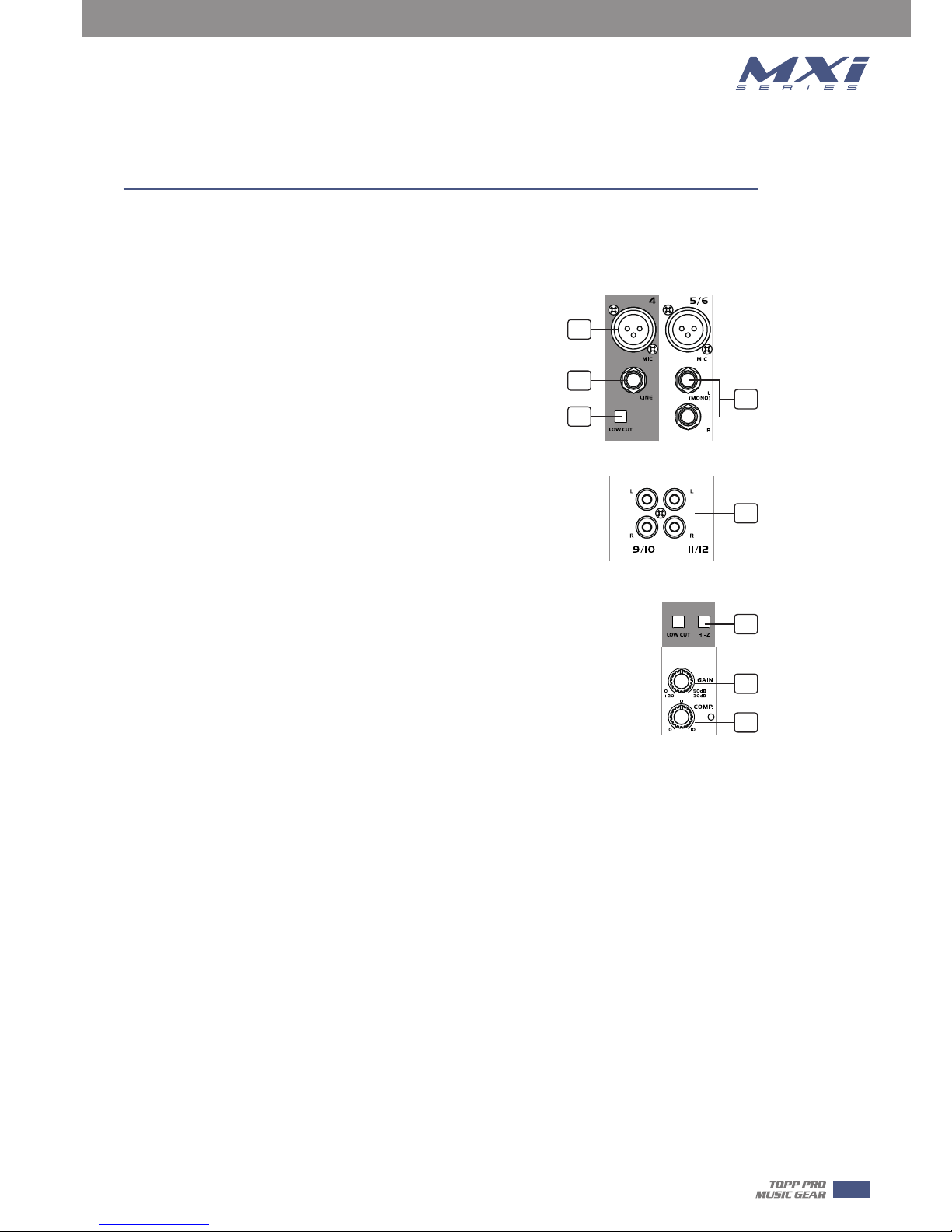
1. MIC INPUT JACKS ( CH 1 to 7/8 for 12 channels or CH 1 to
9/10 for 14 channels or CH 1 to 11/12 for 16 channels )
These are balanced XLR-type microphone input jacks
2. LINE INPUT JACKS ( CH 1 to 4 for 12 channels or CH 1 to 6
for 14 channels or CH 1 to 8 for 16 channels )
These are balanced TRS phone-jack line inputs.
You can connect either balanced or unbalanced phone plugs to
these jacks.
3. LINE INPUT JACKS ( CH 5/6 to 7/8 for 12 channels or CH 7/8
to 9/10 for 14 channels or CH 9/10 to 11/12 for 16 channels )
They are organized in stereo pair and provided with 1/4" TRS
sockets. It is used to connect the stereo device, plug both the left
input and the right input. Using the left input if connect a mono
input signal to the stereo channel, the output signal will appear
on both sides.
4. LOW CUT
By pressing this button you will activate a 75Hz low frequency
filter with a slope of 18dB per octave. You can use this facility to
reduce the hum noise infected by the mains power supply, or the
stage rumble while using a microphone.
5. RCA INPUT JACKS ( CH 9/10 to 11/12 for 12 channels or 11/12 to 13/14 for 14 channels or
CH 13/14 to 15/16 for 16 channels )
They are organized in stereo pair and provided with RCA sockets. It is used to connect the stereo
device, plug both the left input and the right input.
6. HI-Z
To change to a high impedance input, push the appropriate hi-z switch.
7. GAIN CONTROL
Adjusts the input signal level. To achieve the best balance between S / N and dynamic range,
adjust the level so that the peak LED indicator lights occasionally only on the highest input
transients. For each channel the MIC input adjustment range of the Gain is 0 to 50dB and the
sensitivity of line input is +20 to -30dB.
8. COMP CONTROL
Adjust the amount of compression applied to the channel. Turn the knob to the right to increase
the compression ration and the output gain will automatically adjusted. The result is smoother,
more even dynamics because louder signals are attenuated which the overall level is boosted.
5
Control Elements
3
5
6
7
8
1
2
4
4
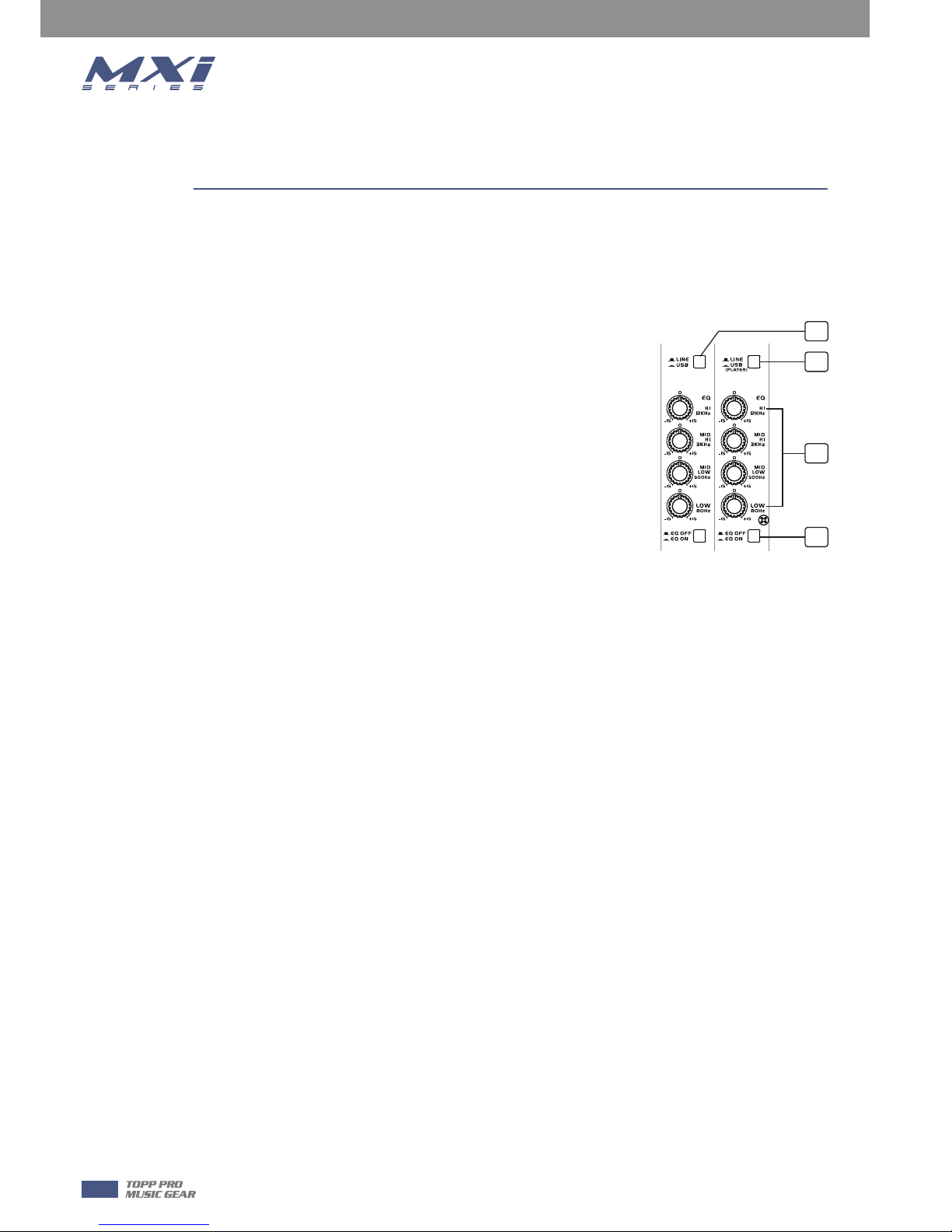
9. LINE/USB
By pressing this button, it will switch to the USB mode, then the USB signal can be sent to this
channel; by releasing this button, the LINE IN inputs signal will send to the line input channels.
10. LINE/USB PLAYER
by pressing this button, it will switch to the USB PLAYER mode,
then the signal of USB PLAYER module sent to this channel;
11. EQUALISER CONTROLS
There are 3-band EQ with sweepable MID on all mono input
channel 1-4/1-6/1-8: HI, MID and LOW band. There are 4-band
fixed frequency EQ on the stereo channel 5-12/7-14/9-16: HI, HI-
MID, MID-LOW and LOW band. All bands provide up to 15 dB of
boost or cut.
--HI
If you turn this control up, you will boost all the frequencies above
12 kHz (shelving filter). You will add transparency to vocals and
guitar and also make cymbals crispier. Turn the control down to
cut all frequencies above 12 kHz In such way, you can reduce
sibilances of human voice or reduce the hiss of a Tape player.
--MID
This is a peaking filter and it will boost/cut frequencies from 100 Hz to 8 kHz depending on the
position of the MID freq control. This control will affect especially upper male and lower female
vocal ranges and also the harmonics of most musical instruments.
--HI-MID
This control gives you up to 15 dB boost or cut at 3 kHz. It is useful for controlling voice. It can
accurately polish your performance via adjusting this knob.
--MID-LOW
This control gives you up to 15 dB boost or cut at 500 Hz.
--LOW
If you turn this control up, you will boost all frequencies below 80 Hz. You will give more punch
to bass drum and bass guitar and make the vocalist more "macho". Turn it down, you will cut all
the frequencies below 80 Hz. In this way, you can avoid low frequency vibrations and resonance
thus preserving the life of your woofers.
12. EQ SWITCH
This switch allows the user to use the EQ Section in signal path. Of course it can be used to make
A/B comparisons between equalized signal and not equalized signal.
It also can be used to apply equalization at a certain point of the show, excluding it when it's not
necessary.
6
Control Elements
10
11
12
9
4
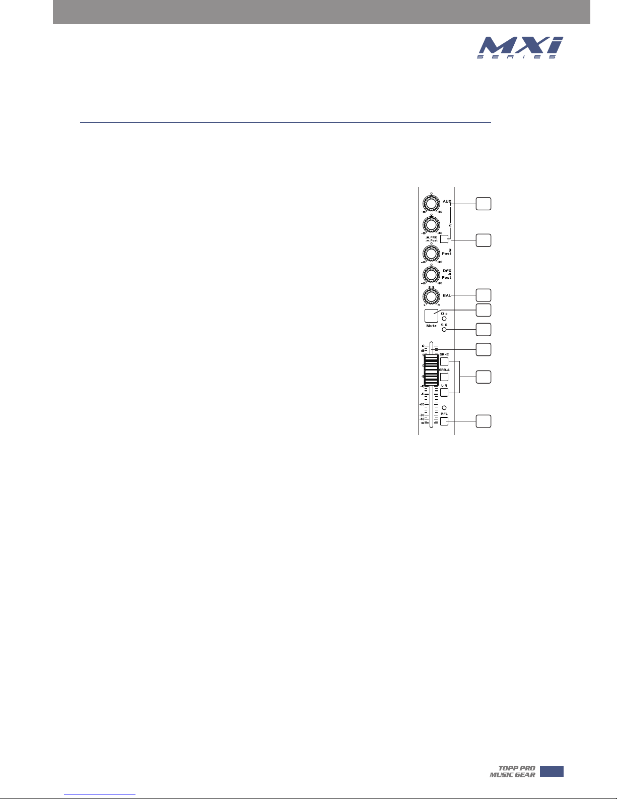
13. AUX SEND CONTROLS
These four controls are used to adjust the level of the respective signal sent to AUX bus and
their adjustable range is from -∞ to +10 dB .
14. PRE/POST
AUX1 and AUX2 can be switched to PRE/POST-FADER via the PRE/POST
button, so, generally, they can be used for monitor application and effects
& sound processors input. AUX3 and AUX4 are configured as POST-Faders.
15. PAN / BAL CONTROL.
The PAN control determines the stereo positioning of the channel signal on
the stereo L and R buses.The BAL control knob sets the balance between
left and right channels. Signal input through the stereo L/R bus.
16. MUTE
Each channel is equipped with the MUTE button, pressing this button is
equal to turning the fader down, which can mute the corresponding
channel output except for the PRE AUX sends, channel INSERT send and
PFL, and the MUTE LED will illuminate.
17. SIG/CLIP
Indicate that the channel's incoming audio signal is with in an optimal
range.
18. CHANNEL LEVEL
This fader will adjust the overall level of this channel and set the amount of signal sent to the
main output.
19. GR1-2/GR 3-4/L-R
Each channel provides three push-buttons: GR1-2, GR3-4, L-R . The three buttons can be
considered as signal assignment switches. Pressing the GR1-2 will assign the channel signal to
GROUP1-2, you can depend on the PAN switch to adjust the amount of channel signal sent to the
GR1versus GR2, when turns the PAN to completely left, then the signal can be only controlled
by GROUP1 and viceversa. In the same way, pressing the GR3-4 or L-R will assign the channel
signal to GROUP3-4 or MAIN MIX L-R, and will also be affected by PAN.
20. PFL
Each channel is equipped with the PFL button, pressing this button which the corresponding
signal send will be routed to CTRL ROOM/PHONES outputs and METER display.
21. GROUPS LEVEL
These faders are used to control the levels of the signal send to the GROUPS OUT, the
adjustable range goes from -∞ to +10 dB. Any channel that is assigned to the groups, not muted
and not turned down will be assigned to the GROUPS OUT.
7
Control Elements
13
14
15
19
16
17
18
20
4
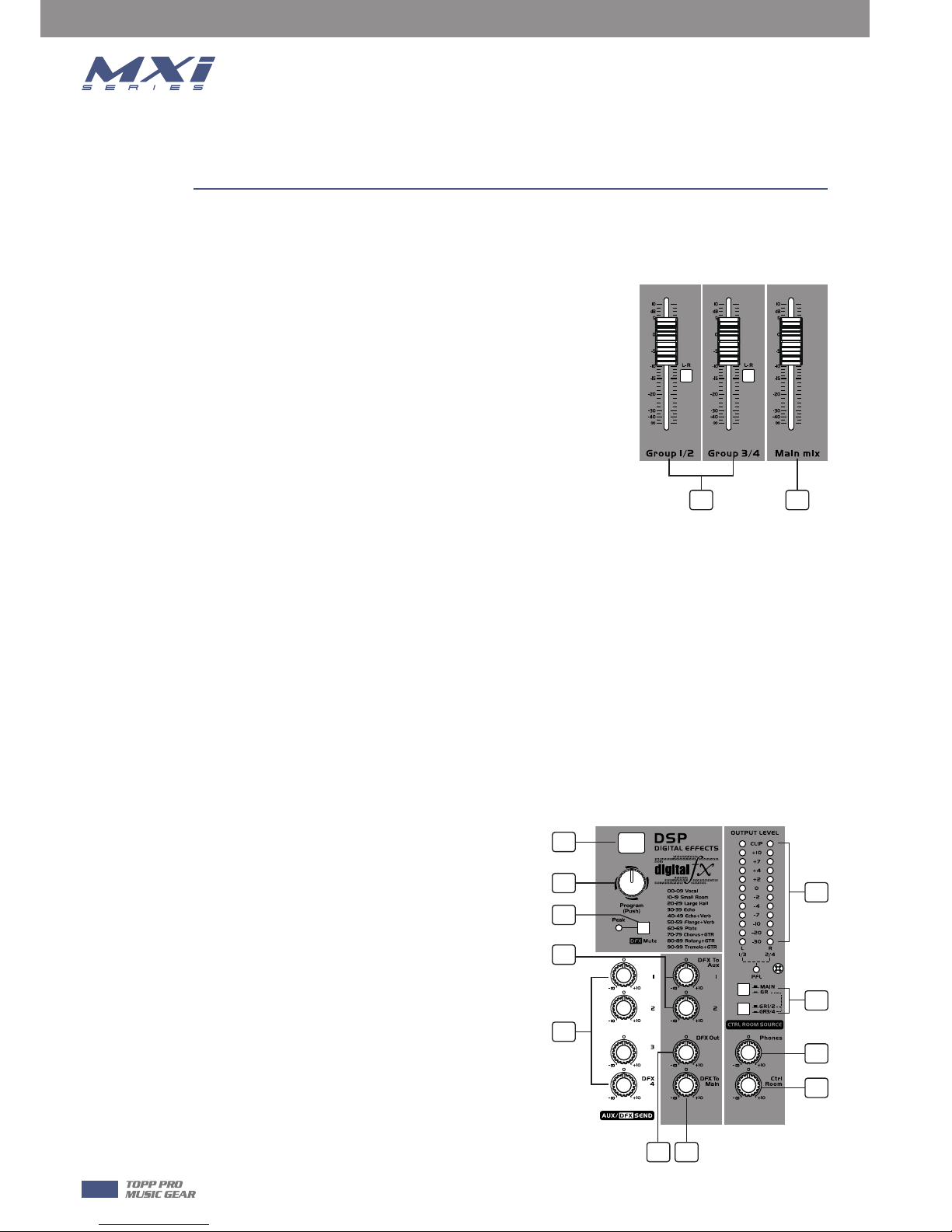
22. MAIN MIX LEVEL
This fader is used to set the amount of signal sent to the main mix output.
23. DIGITAL EFFECTS
It displays the selected preset.
24. PROGRAM(PUSH)
Adjust this knob to select the right effect you wish to perform.
There are totally 100 options for you: Echo, Vocal, Plate and
versatile two-effect combination.
When you are satisfied the right preset, please push this knob
to store this preset you want.
25. DFX/MUTE
Disables the internal effects processor; in this case the red
"PEAK" LED will be lit permanently.
26. DFX TO AUX SEND1/2
The both rotary knobs assign the DFX signals to their respective AUX SEND outputs.
27. AUX SEND CONTROLS
These four controls are used to determine the master AUX SEND levels, which can be varied from
-∞to +10 dB. When the external effect units which have no input gain control were connected to
mixer, you can get a further +10 dB gain available from these Aux Send outputs.
As to the AUX4, it can also provide the lovable level adjustment for the internal effect signal.
28. DFX OUT
These control is used to determine the internal DSP module levels and DFX sends output, which
can be varied from -∞ to +10dB
29. DFX TO MAIN
This control is used to assign the signal from FX to
MAIN MIX output.
30. OUTPUT LEVEL
This stereo 12 segments LED meter will be
indicate the level of overall output signal.
31. MAIN/GR
If you release the MAIN/GR button, the signal will
be cone from the MAIN MIX output, it will not be
affected by pressing both GR1/2 and GR3/4
button. When you push down the MAIN GR
button and press both GR1/2 and GR3/4 at the
same time, the signal will be come from the GR3/4
output. When you release the GR1/2 and GR3/4,
the signal will be come from the GR1/2 output.
Control Elements
21 22
23
24
27
33
32
31
25
28 29
26
30
8
4
 Loading...