

Page 1

Contactless IC Card Reader/Writer
TR63036(E)
User’s Manual
Copyright Toppan Forms Co., Ltd. 2014
Version 0.91
2014-10-08
Toppan Forms Co., Ltd.
FeliCa is a technology developed by Sony Corporation.
FeliCa is a trademark of Sony Corporation.
MIFARE is a trademark of NXP B.V.
I-Code is a trademark of NXP B.V.
All other brands, product names and trademarks are the property of their respective owners.
The TM or ® markings are omitted in this document.
Reproduction in whole or in part is prohibited without the prior written consent of the copyright
owner.
The contents of this document may be altered without prior notice.
Page 2

Revision history
Date Revision Description
Oct/08/2014 0.91 First issue
[TR63036(E)User’sManual]
i
Page 3

Important notice
For use in the United States:
1.Module User Requirements
FCC 15.212(a)(ⅵ)(A)
The host device must contain the following permanent labeling on the exterior
of the host device as follows:
Contains FCC ID: ORKTR63036-E
FCC 15.19(a)(3)
The host device shall bear the following statement in a conspicuous location
on the device:This device complies with part 15 of the FCC Rules. Operation is
subject to the following two conditions: (1) This device may not cause harmful
interference, and (2) this device must accept any interference
received,including interference that may cause undesired operation.
When the device is so small or for such use that it is not practicable to place
the statement specified under paragraph 15.19(a)(3) of this section on it, the
information required by this paragraph shall be placed in a prominent
location in the instruction manual or pamphlet supplied to the user or,
alternatively,shall be placed on the container in which the device is marketed.
2.The user manual of the host device must contain the following paragraph:
FCC 15.21
Caution: Changes or modifications not expressly approved by the party
responsible for compliance could void the user’s authority to operate the
equipment.
FCC15.105(b)
This equipment has been tested and found to comply with the limits for a Class
B digital device, pursuant to part 15 of the FCC Rules. These limits are
designed to provide reasonable protection against harmful interference in a
residential installation. This equipment generates, uses and can radiate
radio frequency energy and,if not installed and used in accordance with the
instructions, may cause harmful interference to radio communications.
However, there is no guarantee that interference will not occur in a particular
installation. If this equipment does cause harmful interference to radio or
[TR63036(E)User’sManual]
ii
Page 4

television reception, which can be determined by turning the equipment off
and on, the user is encouraged to try to correct the interference by one or more
of the following measures:
—Reorient or relocate the receiving antenna.
—Increase the separation between the equipment and receiver.
—Connect the equipment into an outlet on a circuit different from that
to which the receiver is connected.
—Consult the dealer or an experienced radio/TV technician for help.
IMPORTANT NOTE:
ⅰ.That module is limited to OEM installation only.
ⅱ.That OEM integrators is responsible for ensuring that the end-user has no
manual
instructions to remove or install module.
ⅲ .That module is limited to installation in mobile or fixed applications,
according
to Part 2.1091(b)
ⅳ.That separate approval is required for all other operating configurations,
Manual Information to the End User
The OEM integrator has to be aware not to provide information to the end user
regarding
how to install or remove this RF module in the user’s manual of the end product
which
integrates this module. The end user manual shall include required regulatory
information/warning as below.
ⅰ .End-users must be provided with transmitter/antenna installation
requirements
and
operating conditions for satisfying RF exposure compliance.
ⅱ.A separate section should clearly state “FCC RF Exposure requirements:”
ⅲ.Required operating conditions for end users
ⅳ .Antenna/or transmitter installation requirements, where relevant (For
example:
The antenna used with this module must be installed to provide a separation
distance of at least 20cm from all persons, and must not transmit
simultaneously
with any other antenna or transmitter.)
[TR63036(E)User’sManual]
iii
Page 5
For use in the EU:
This device can be used without restrictions in all EU member states and EFTA
countries.
Declaration of Conformity with regard to the R&TTE Directive 1999/5/EC
Hereby, Toppan Forms Co., Ltd., declares that this IC Card
English
Finnish
Dutch
Reader/Writer TR63036(E) is in compliance with the essential
requirements and other relevant provisions of Directive 1999/5/EC.
Toppan Forms Co., Ltd. vakuuttaa täten että IC Card
Reader/Writer TR63036(E) tyyppinen laite on direktiivin
1999/5/EY oleellisten vaatimusten ja sitä koskevien direktiivin
muiden ehtojen mukainen.
Hierbij verklaart Toppan Forms Co., Ltd. dat het toestel IC Card
Reader/Writer TR63036E) in overeenstemming is met de essentiële
eisen en de andere relevante bepalingen van richtlijn 1999/5/EG
Bij deze verklaart Toppan Forms Co., Ltd. dat deze IC Card
Reader/Writer TR63036(E) voldoet aan de essentiële eisen en aan
de overige relevante bepalingen van Richtlijn 1999/5/EC.
Par la présente Toppan Forms Co., Ltd. déclare que l'appareil IC
Card Reader/Writer TR63036(E) est conforme aux exigences
essentielles et aux autres dispositions pertinentes de la directive
1999/5/CE
French
Par la présente, Toppan Forms Co., Ltd. déclare que ce IC Card
Reader/Writer TR63036(E) est conforme aux exigences essentielles
et aux autres dispositions de la directive 1999/5/CE qui lui sont
applicables
Härmed intygar Toppan Forms Co., Ltd. att denna IC Card
Reader/Writer TR63036(E) står I överensstämmelse med de
Swedish
väsentliga egenskapskrav och övriga relevanta bestämmelser som
framgår av direktiv 1999/5/EG.
Undertegnede Toppan Forms Co., Ltd. erklærer herved, at følgende
Danish
udstyr IC Card Reader/Writer TR63036(E) overholder de
væsentlige krav og øvrige relevante krav i direktiv 1999/5/EF
[TR63036(E)User’sManual]
iv
Page 6
Hiermit erklärt Toppan Forms Co., Ltd., dass sich
dieser/diese/dieses IC Card Reader/Writer TR63036(E) in
Übereinstimmung mit den grundlegenden Anforderungen und den
anderen relevanten Vorschriften der Richtlinie 1999/5/EG
German
Greek
Italian
Spanish
befindet". (BMWi)
Hiermit erklärt Toppan Forms Co., Ltd. die Übereinstimmung des
Gerätes IC Card Reader/Writer TR63036(E) mit den
grundlegenden Anforderungen und den anderen relevanten
Festlegungen der Richtlinie 1999/5/EG. (Wien)
ΜΕ ΤΗΝ ΠΑΡΟΥΣΑ Toppan Forms Co., Ltd. ΔΗΛΩΝΕΙ ΟΤΙ IC
Card Reader/Writer TR63036(E) ΣΥΜΜΟΡΦΩΝΕΤΑΙ ΠΡΟΣ ΤΙΣ
ΟΥΣΙΩΔΕΙΣ ΑΠΑΙΤΗΣΕΙΣ ΚΑΙ ΤΙΣ ΛΟΙΠΕΣ ΣΧΕΤΙΚΕΣ
ΔΙΑΤΑΞΕΙΣ ΤΗΣ ΟΔΗΓΙΑΣ 1999/5/ΕΚ
Con la presente Toppan Forms Co., Ltd. dichiara che questo IC
Card Reader/Writer TR63036(E) è conforme ai requisiti essenziali
ed alle altre disposizioni pertinenti stabilite dalla direttiva
1999/5/CE.
Por medio de la presente Toppan Forms Co., Ltd. declara que el IC
Card Reader/Writer TR63036(E) cumple con los requisitos
esenciales y cualesquiera otras disposiciones aplicables o exigibles
Portuguese
de la Directiva 1999/5/CE
Toppan Forms Co., Ltd. declara que este IC Card Reader/Writer
TR63036(E) está conforme com os requisitos essenciais e outras
disposições da Directiva 1999/5/CE.
[TR63036(E)User’sManual]
v
Page 7

For Use in Canada:
Canada, Industry Canada (IC) Notices
This Class B digital apparatus complies with Canadian ICES-003 and RSS-210.
Operation is subject to the following two conditions:
(1) this device may not cause inteference, and
(2) this device must accept any interference, including interference that may
cause undesired operation of the device.
This device complies with Industry Canada licence-exempt RSS standard(s).
Operation is subject to the following two conditions:
(1) this device may not cause interference, and
(2) this device must accept any interference, including interference that may
cause undesired operation of the device.
Under Industry Canada regulations, this radio transmitter may only operate
using an antenna of a type and maximum (or lesser) gain approved for the
transmitter by Industry Canada. To reduce potential radio interference to other
users, the antenna type and its gain should be so chosen that the equivalent
isotropically radiated power (e.i.r.p.) is not more than that necessary for
successful communication.
IMPORTANT NOTE: Radiation Exposure Statement
The available scientific evidence does not show that any health problems are
associated with using low power wireless devices.
There is no proof, however, that these low power wireless devices are absolutely
safe. Low power Wireless devices emit low levels of radio frequency energy (RF)
in the microwave range while being used. Whereas high levels of RF can
produce health effects (by heating tissue), exposure of low-level RF that does
not produce heating effects causes no known adverse health effects. Many
studies of low-level RF exposures have not found any biological effects. Some
studies have suggested that some biological effects might occur, but such
findings have not been confirmed by additional research. This device
(TR63036(E)) has been tested and found to comply with IC radiation exposure
limits set forth for an uncontrolled environment and meets RSS-102 of the IC
radio frequency (RF) Exposure rules.
--------------------------------------------------------------------------------------------------------------
Canada, avis d'Industry Canada (IC)
Cet appareil numérique de classe B est conforme aux normes canadiennes
ICES-003 et RSS-210.
Son fonctionnement est soumis aux deux conditions suivantes:
(1) cet appareil ne doit pas causer d'interférence et
(2) cet appareil doit accepter toute interférence, notamment les interférences
qui peuvent affecter son fonctionnement
[TR63036(E)User’sManual]
vi
Page 8

Le présent appareil est conforme aux CNR d'Industrie Canada applicables aux
appareils radio exempts de licence.
L'exploitation est autorisée aux deux conditions suivantes :
(1) l'appareil ne doit pas produire de brouillage, et
(2) l'utilisateur de l'appareil doit accepter tout brouillage radioélectrique subi,
même si le brouillage est susceptible d'en compromettre le fonctionnement.
Conformément à la réglementation d'Industrie Canada, le présent émetteur
radio peut fonctionner avec une antenne d'un type et d'un gain maximal (ou
inférieur) approuvé pour l'émetteur par Industrie Canada. Dans le but de
réduire les risques de brouillage radioélectrique à l'intention des autres
utilisateurs, il faut choisir le type d'antenne et son gain de sorte que la
puissance isotrope rayonnée équivalente (p.i.r.e.) ne dépasse pas l'intensité
nécessaire à l'établissement d'une communication satisfaisante.
NOTE IMPORTANTE: Déclaration de l'exposition de la radiation
Les connaissances scientifiques dont nous disposons n’ont mis en évidence
aucun problème de santé associé à l’usage des appareils sans fil à faible
puissance. Nous ne sommes cependant pas en mesure de prouver que ces
appareils sans fil à faible puissance sont entièrement sans danger. Les
appareils sans fil à faible puissance émettent une énergie radioélectrique (RF)
très faible dans le spectre des micro-ondes lorsqu’ils sont utilisés. Alors qu’une
dose élevée de RF peut avoir des effets sur la santé (en chauffant les tissus),
l’exposition à de faibles RF qui ne produisent pas de chaleur n’a pas de mauvais
effets connus sur la santé. De nombreuses études ont été menées sur les
expositions aux RF faibles et n’ont découvert aucun effet biologique. Certaines
études ont suggéré qu’il pouvait y avoir certains effets biologiques, mais ces
résultats n’ont pas été confirmés par des recherches supplémentaires.
TR63036(E) a été testé et jugé conforme aux limites d’exposition aux
rayonnements énoncées pour un environnement non contrôlé et respecte les
règles d’exposition aux fréquences radioélectriques (FR) RSS-102 de l’IC.
Labelling Requirements for the Host device
The host device shall be properly labelled to identify the modules within the host
device. The Industry Canada certification label of a module shall be clearly visible
at all times when installed in the host device, otherwise the host device must be
labelled to display the Industry Canada certification number of the module,
preceded by the words “Contains transmitter module”, or the word “Contains”, or
similar wording expressing the same meaning, as follows:
Contains transmitter module IC:
XXXXXX-YYYYYYYYYYY where XXXXXX-YYYYYYYYYYY is the module’s
certification number.
The applicant for equipment certification of the module shall provide with each
unit of the module either a label such as described above, or an explanation and
instructions to the user as to the host device labelling requirements.
[TR63036(E)User’sManual]
vii
Page 9

Table of Contents
1. Introduction ........................................................................................................................................... 1
2. Description ............................................................................................................................................. 1
3. Specification ........................................................................................................................................... 2
4. Block Diagram ....................................................................................................................................... 4
5. Host Interface ........................................................................................................................................ 5
5.1. USB Connector ................................................................................................................................ 5
5.2. USB pin assignment ....................................................................................................................... 5
5.3. UART Connector ............................................................................................................................. 6
5.4. UART Pin assignment .................................................................................................................... 6
6. Electrical characteristics ...................................................................................................................... 7
6.1. Absolute maximum rating .............................................................................................................. 7
6.2. Operating Environment .................................................................................................................. 7
6.3. Input characteristics ....................................................................................................................... 8
6.4. Output characteristics .................................................................................................................... 8
6.5. Current consumption ...................................................................................................................... 9
7. Module Outline .................................................................................................................................... 10
8. Module structure .................................................................................................................................. 11
9. Cautions ............................................................................................................................................... 12
9.1. Handling care ................................................................................................................................ 12
9.2. Operating environment ................................................................................................................ 12
[TR63036(E)User’sManual]
viii
Page 10

Figure and Table
Figure 4-1 Block Diagram ........................................................................................................................ 4
Figure 7-1 Module outline ...................................................................................................................... 10
Figure 8-1 Module structure ................................................................................................................... 11
Table 3-1 Specification .............................................................................................................................. 2
Table 5-1 Connector on board ................................................................................................................... 5
Table 5-2 Cable connector ......................................................................................................................... 5
Table 5-3 Pin assignment ......................................................................................................................... 5
Table 5-4 Connector on board ................................................................................................................... 6
Table 5-5 Cable connector ......................................................................................................................... 6
Table 5-6 Pin assignment ......................................................................................................................... 6
Table 6-1 Absolute maximum rating ....................................................................................................... 7
Table 6-2 Operating Environment ........................................................................................................... 7
Table 6-3 Input characteristics ................................................................................................................ 8
Table 6-4 Output characteristics .............................................................................................................. 8
Table 6-5 Current consumption ............................................................................................................... 9
Table 8-1 Description of module structure ............................................................................................. 11
[TR63036(E)User’sManual]
ix
Page 11

1. Introduction
This document describes the functionality and electrical specification of the contactless IC Card
Reader/Write “TR63036(E).
2. Description
Two types of host interfaces
・Full speed USB interfaces. Supports USB bus powered operation
・UART interface
Compliance
・Japan (Type Designation)
Inductive communication unit / ARIB STD-T82
・The United States
FCC 【Part15 subpartC CFR15.225】
・EU
CE 【EN302 291-2 V1.1.1】
VCCI Class B compliant
Supported communication protocols
JIS X 6319-4
ISO/IEC 14443 Type A(MIFARE)/Type B
ISO/IEC 15693
[TR63036(E)User’sManual]
1
Page 12
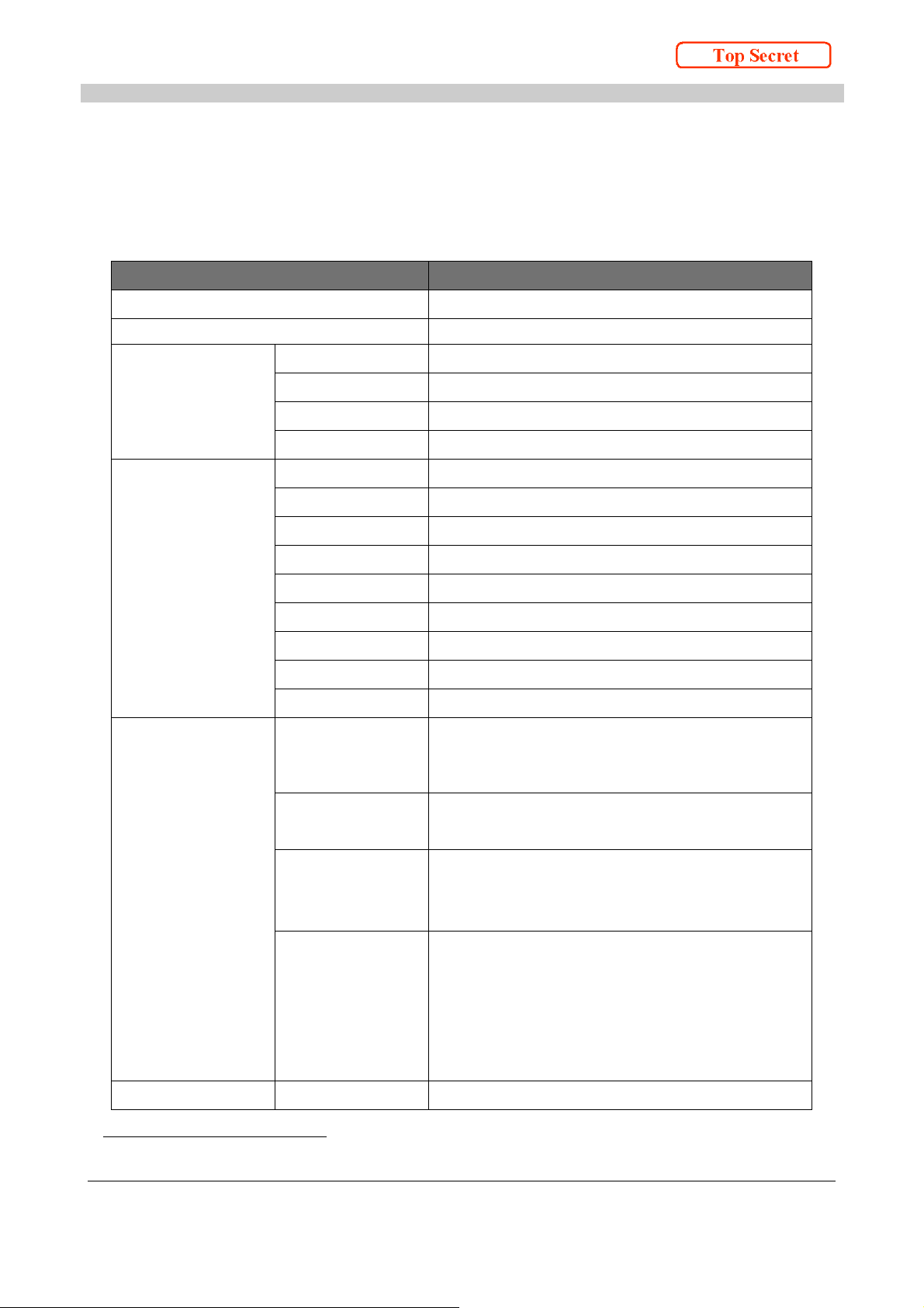
3. Specification
Parameter Description
Table 3-1 Specification
Model name
TR63036(E)
Function Contactless IC Card Reader/Writer
Host USB Interface1 Power supply
Compliant to
Baud rate
Connector
Host UART
Interface
1
Power supply
Method
Baud rate
Start bit
Data length
Stop bit
Parity
Bit order
Connector
RF Interface Type Designation /
Japan
USB bus powered / DC+5V / 250mA max
USB 2.0 Full Speed
12Mbps
USB MiniB / female
DC+5V / 250mA max
Full duplex Asynchronous
Up to 115.2kbps / Selective by Host
1bit
8bit
1bit
none
LSB first
SM05B-SRSS-GTBLFSN / JST
Contactless inductive communication unit
Model:TR63036(E)
Type # : AC-******
RF carrier
13.56MHz
frequency
RF bit rate
JIS X 6319-4:211.875kbps / 423.750kbps
ISO/IEC 14443:105.9375kbps
ISO15693:26.5kbps
Communication
range / Informative
FeliCa
Toppan Forms standard card: 50mm
Suica: 30mm
MIFARE: 50mm / DESfire: 30mm
Type B card: 20mm
I-Code SLI: 50mm
User interface LED
Green color LED
1
USB interface and UART interface cannot be used simultaneously.
[TR63036(E)User’sManual]
2
Page 13
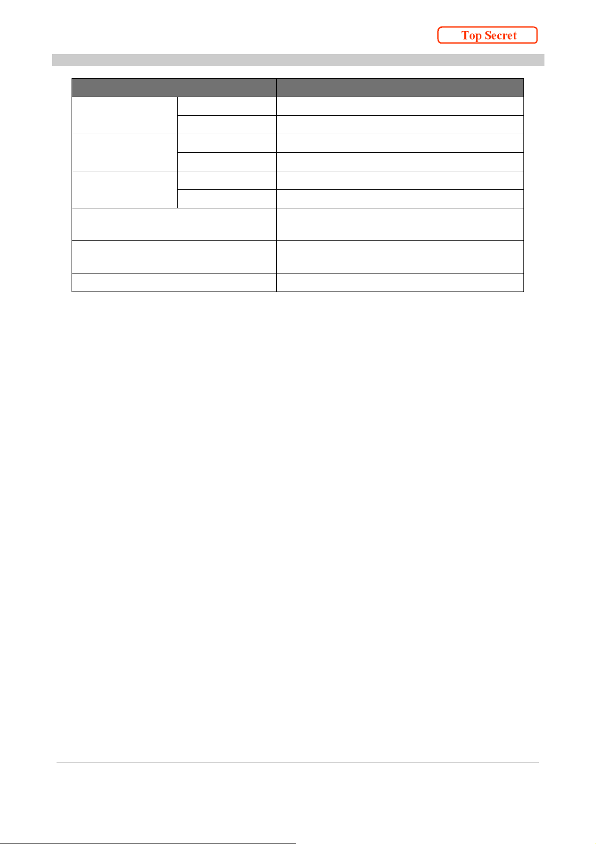
Parameter Description
Operation
environment
Storage
environment
Temp er at ur e
Humidity
Temp er at ur e
Humidity
Outline Size
Weight
FCC
-20 to +60 ℃
30 to 90 %RH / No dew condensation
-20 to +60 ℃
30 to 90 %RH / No dew condensation
5 × 48 × 71mm
10g
Part15 subpartC CFR15.225 compliant
Part15 subpartB ANSI C63.4-2003 compliant
CE
EN302 291-2 V1.1.1 compliant
EN301 489-3 V1.6.1 compliant
VCCI
VCCI Class B compliant
[TR63036(E)User’sManual]
3
Page 14
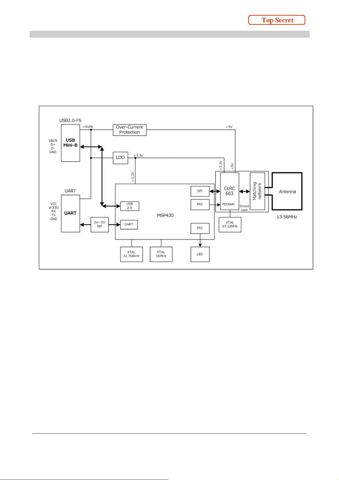
4. Block Diagram
Figure 4-1 Block Diagram
[TR63036(E)User’sManual]
4
Page 15
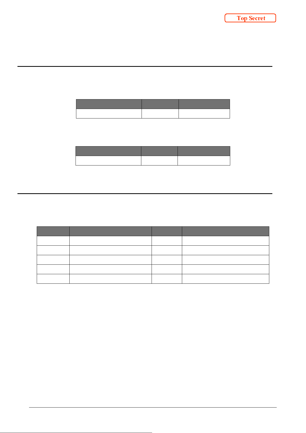
5. Host Interface
5.1. USB Connector
Table 5-1 Connector on board
Model # Maker Note
UX60SC-MB-5ST HIROSE
Model # Maker Note
USB mini B / male in general
5.2. USB pin assignment
pin # Signal Feature Note
1 VBUS POWER Power supply +5V
2 D- I/O USB-D-
3 D+ I/O USB-D+
TID:60001382
Table 5-2 Cable connector
Table 5-3 Pin assignment
4 (ID) NC No connection
5 GND GND Ground
[TR63036(E)User’sManual] 5
Page 16
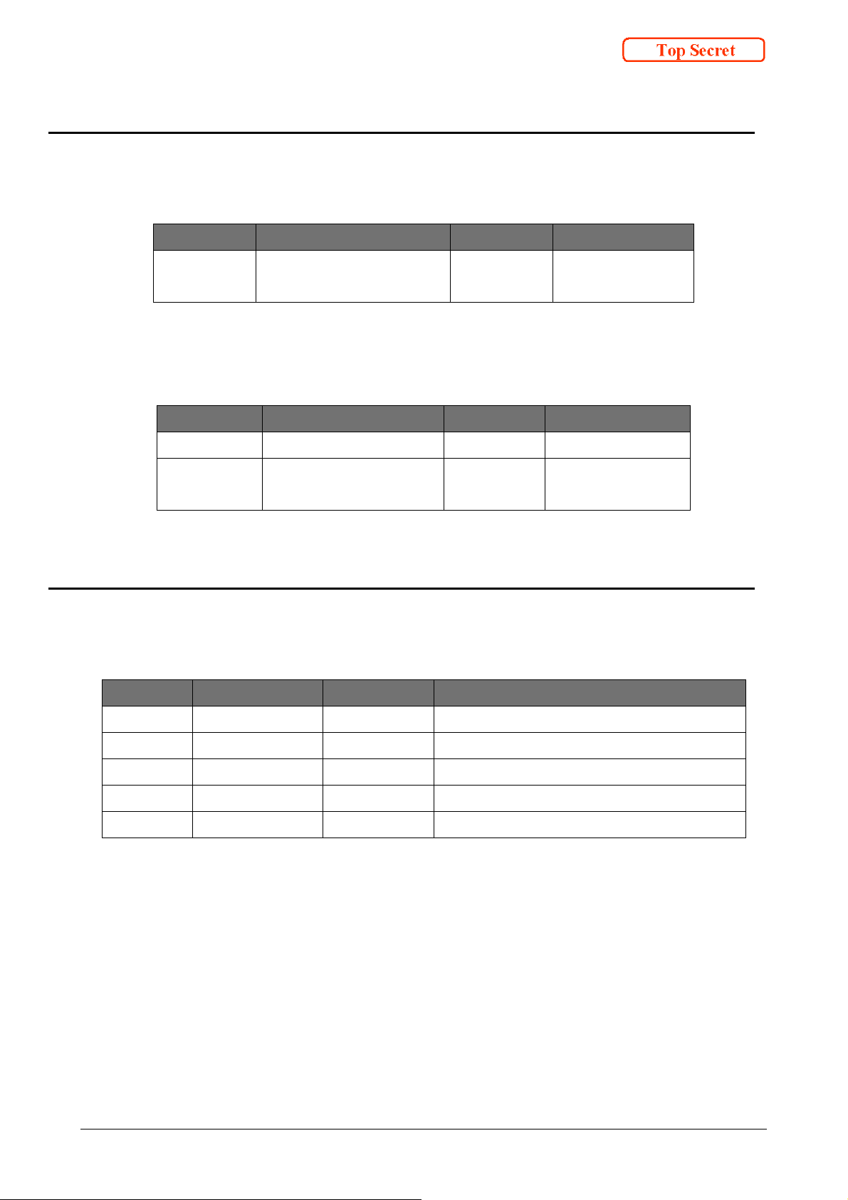
5.3. UART Connector
Table 5-4 Connector on board
Item
Connector SM05B-SRSS-GTBLFSN JST P=1.0 / Gold
Item
Socket SHR-05V-S-B JST
Contact SSH-003T-P0.2-H JST AWG32 to 28 /
5.4. UART Pin assignment
Model# Maker Note
plate
Table 5-5 Cable connector
Model# Maker Note
Gold plate
Table 5-6 Pin assignment
pin # Signal Feature Note
1 VCC POWER Power supply +5V
2 VCCIO IN TX,RX voltage level / Chip Select
3 RX IN Receive signal
4 TX OUT Transmit signal
5 GND GND Ground
[TR63036(E)User’sManual] 6
Page 17
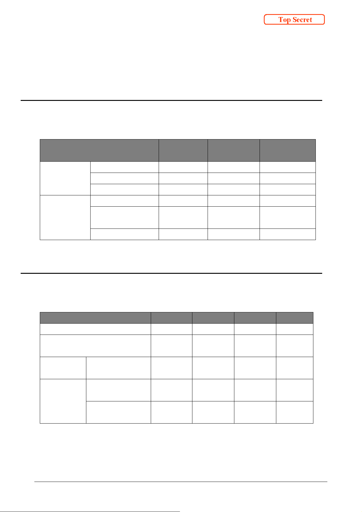
6. Electrical characteristics
6.1. Absolute maximum rating
Table 6-1 Absolute maximum rating
Parameter Symbol
USB Supply voltage VBUS 5.5 V
USB-D+ D+ 3.6 V
USB-D- D- 3.6 V
UART Supply voltage VCC 5.5 V
I/O Terminal
Vol ta ge
RX Voltage RX 5.5 V
6.2. Operating Environment
Table 6-2 Operating Environment
Parameter Symbol Min Max Unit
Limiting
Unit
value
VCCIO
5.5 V
Operating temperature range Top -20 +60
Operating humidity range /
No dew condensation
USB Recommended
voltage range
UART Recommended
voltage range
Recommended
voltage range
[TR63036(E)User’sManual] 7
RHop
30 90 %
VBUS 4.75 5.25 V
VCC
4.75 5.25 V
VCCIO
3.0 5.0 V
℃
Page 18
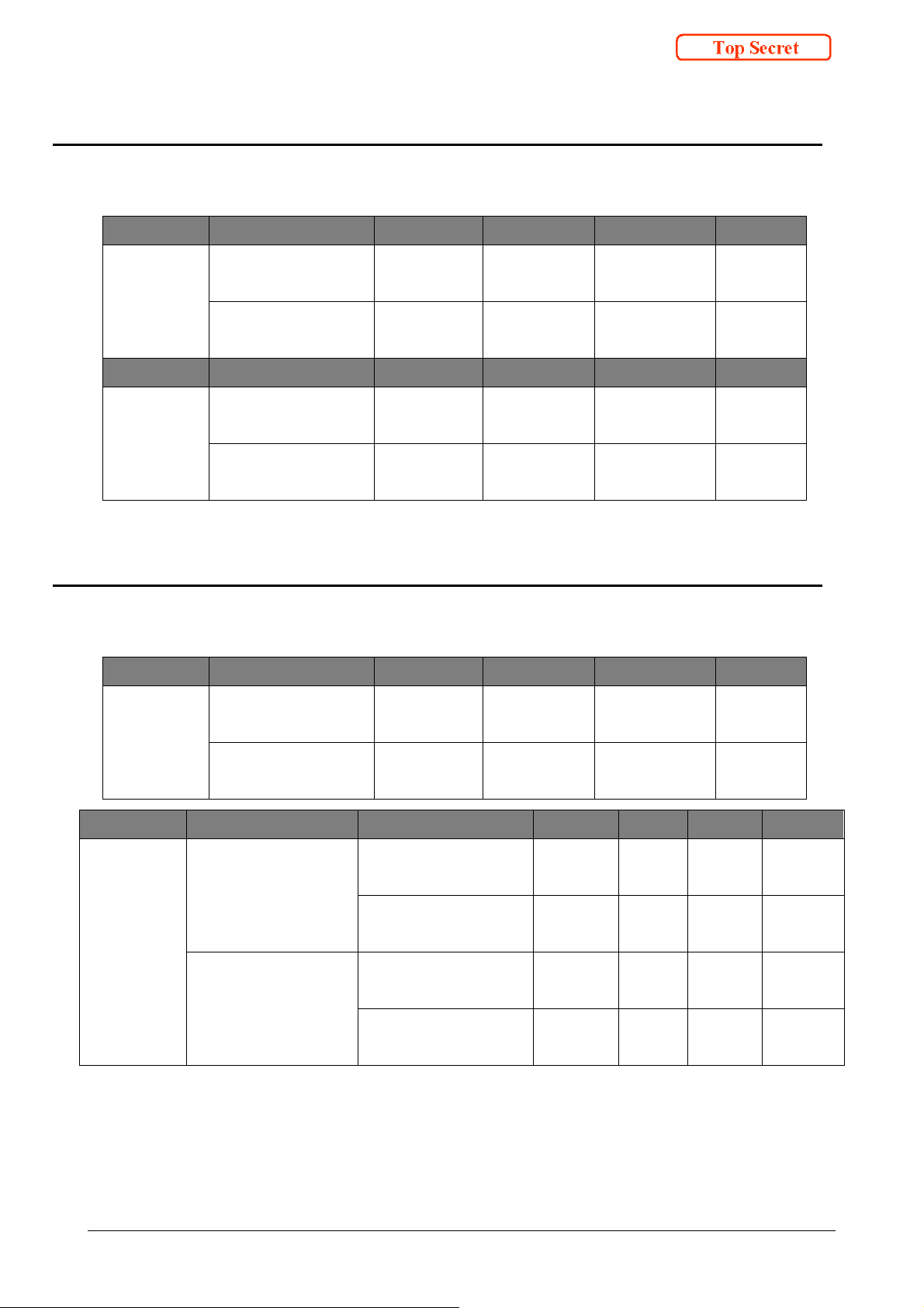
6.3. Input characteristics
Signal Parameter Symbol Min Max Unit
Table 6-3 Input characteristics
Low level input
USB
(D+,D-)
voltage
High level input
voltage
Signal Parameter Symbol Min Max Unit
Low level input
UART
(RX)
voltage
High level input
voltage
6.4. Output characteristics
Table 6-4 Output characteristics
Signal Parameter Symbol Min Max Unit
Low level
USB
output voltage
V
VIH
V
IL
VIH
V
OL
IL
- 0.8 V
V
2.0 -
- 0.8 V
V
2.0 -
0 0.3 V
(D+,D-)
High level
VOH
V
2.8 3.6
output voltage
Signal Condition Parameter Symbol Min Max Unit
3.0V ≦ VCCIO <
Low level output
V
OL
- 0.4 V
4.5V
Output current:
voltage
High level output
VOH
2.4 - V
UART
(TX)
5mA(max)
4.5V ≦ VCCIO ≦
voltage
Low level output
V
OL
- 0.55 V
5.0V
Output current:
voltage
High level output
VOH
3.8 -
5mA(max)
voltage
V
[TR63036(E)User’sManual] 8
Page 19
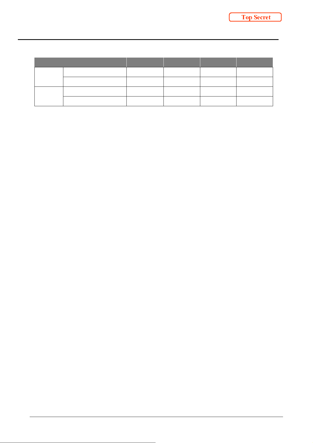
6.5. Current consumption
Parameter Simbol Typ Max Unit
Table 6-5 Current consumption
USB
UART
Supply current I
USB standby current I
Supply current I
VCCIO I
150 250 mA
VBIS
USB-STBY
VCC
VCCIO
2.2 2.5 mA
150 250 mA
5 10 mA
[TR63036(E)User’sManual] 9
Page 20
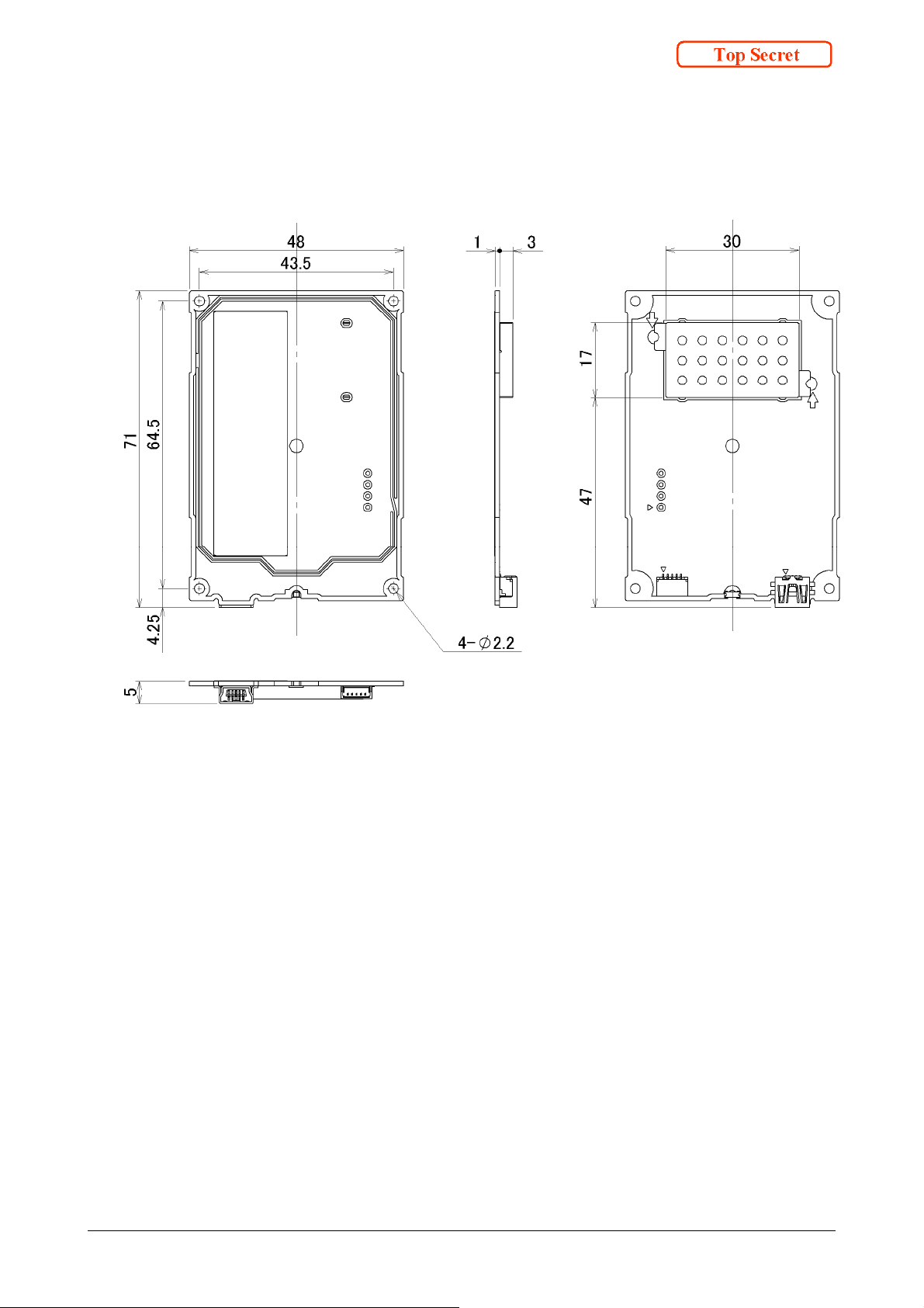
7. Module Outline
Figure 7-1 Module outline
【Unit:mm】
[TR63036(E)User’sManual] 10
Page 21
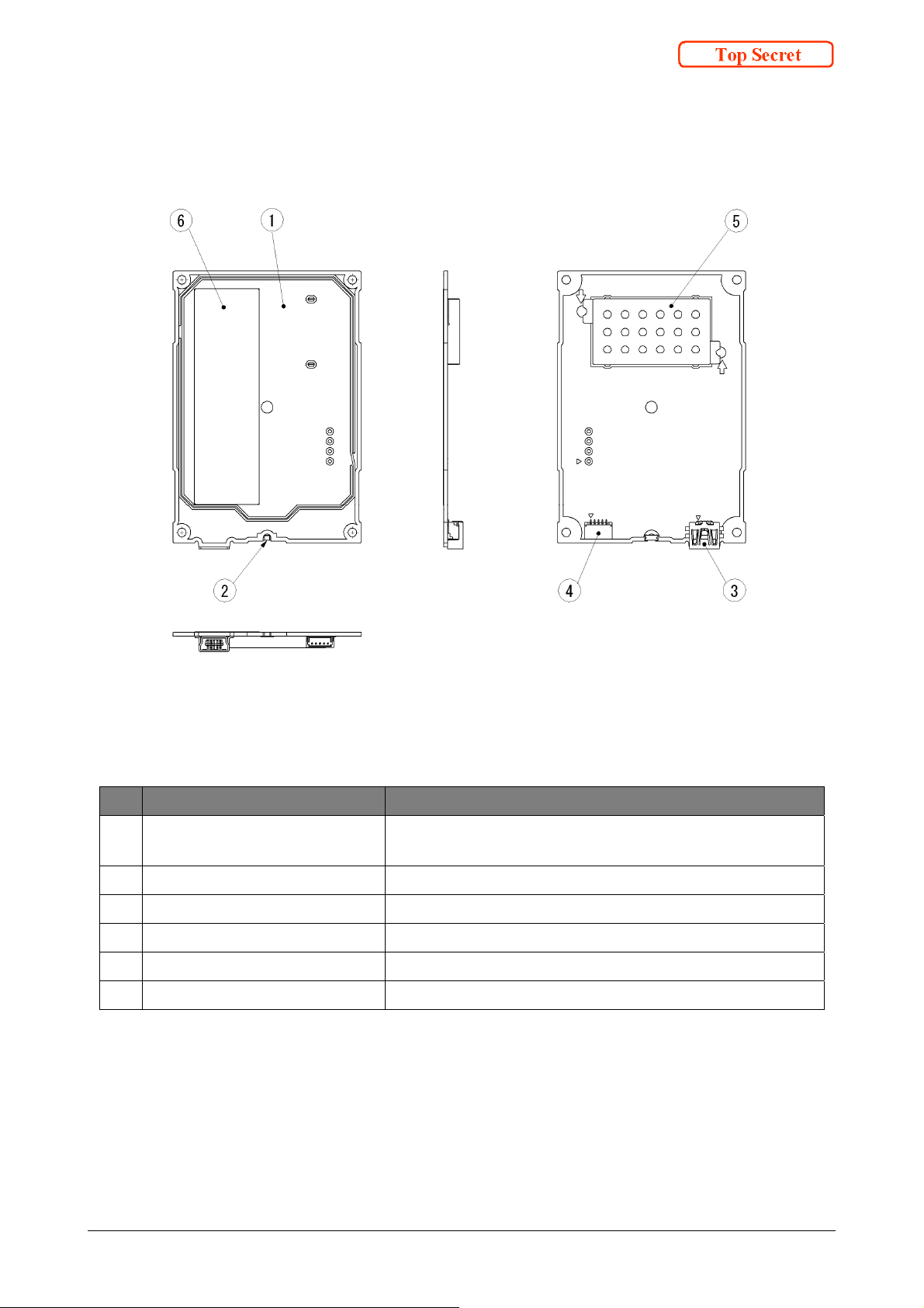
8. Module structure
No. Part
①
RF communication area
②
Monitor LED
③
USB interface connector USB interface connector for Host
④
UART interface connector UART interface connector for Host
⑤
Shielding case
⑥
Label
Figure 8-1 Module structure
Table 8-1 Description of module structure
Description
IC Card communication area, locate the card above this
area.
Monitor LED indicating Reader/Writer status
Shielding case for RF circuitry
Label for product information
[TR63036(E)User’sManual] 11
Page 22

9. Cautions
9.1. Handling care
Any changes or modifications on this product will void the compliance requirement of radio
regulation and user’s authority to operate. The operation of changed or modified product
will result the violation of raw and a penalty might be imposed.
Please avoid the static electricity be fed on this product.
Stress above the absolute maximum rating (limiting value) will permanently and
irreversibly affect the quality and reliability of the product. Please avoid high voltage or
spike noise be fed on any terminals of this product.
9.2. Operating environment
Operating performance of this product shall be confirmed in the exact location where the
product is installed in the user’s final applications.
Any electromagnetic field generated nearby this product or materials that intercept/reflect
the radio wave will interfere with the communication performance of this product.
Locating two or more contactless IC Card Reader or RFID Reader closely each other will
affect the communication performance between Reader and IC card/RFID tag.
This product is designed to be used in the stabile condition. If any vibration or shock on
this product is expected, full evaluation is required to confirm proper operation in prior to
the installation.
A USB hub connected between this product and the Host might cause a failure in
recognizing the Reader/Writer by host and a reduction of communication distance between
the Reader/Writer and an IC Card.
A USB extension cable might cause a failure in recognizing the Reader/Writer by host and
a reduction of communication distance between the Reader/Writer and an IC Card.
[TR63036(E)User’sManual] 12
Page 23

Contactless IC Card Reader/Writer
TR63036(E) User’s Manual
Ver sio n0 .9 1
2014/10/08
Toppan Forms Co., Ltd.
 Loading...