

INSTRUCTIONS FOR INSTALLATION AND USE
K140
AUTOMATION AND ELECTROMECHANICAL DRIVERS
FOR LINEAR SLIDING DOORS WITH ONE OR TWO PANELS
COD. 0P5501
EN
VER 0.0
REV 03.16
installer's manual/original instructions


EN
INDEX
3
EN
INSTRUCTIONS FOR INSTALLATION AND USE
K140
EN
1- GENERAL INFORMATION
1.1- General recommendations...............................................................................................................pag. 04
1.2- General safety rules ........................................................................................................................pag. 04
1.3- Installer.............................................................................................................................................pag. 04
1.4- User..................................................................................................................................................pag. 05
1.5- Servicing...........................................................................................................................................pag. 05
2- TECHNICAL DESCRIPTION
2.1- Rating place and “CE” marking .......................................................................................................pag. 05
2.2- Proper use .......................................................................................................................................pag. 05
2.3- Technical data .................................................................................................................................pag. 06
2.4- Packing ............................................................................................................................................pag. 06
2.5- Models..............................................................................................................................................pag. 07
2.6- Sliding doors with one panel ...........................................................................................................pag. 08
2.7- Description of parts and dimensions ...............................................................................................pag. 09
3- INSTALLATION
3.1- General recommendations...............................................................................................................pag. 11
3.2- Installing the crossbar ......................................................................................................................pag. 11
3.3- Installing the adapter and track........................................................................................................pag. 12
3.4- Installing the carriages on the door..................................................................................................pag. 13
3.5- Fastening and adjustment of the sliding panels...............................................................................pag. 14
3.6- Installing the motor module, belt transmission, belt,logline..............................................................pag. 16
3.7- Fastening the drive brackets on the door panel...............................................................................pag. 18
3.8- Installing the door block ...................................................................................................................pag. 20
3.9- Installing the casing .........................................................................................................................pag. 21
4- ELECTRICAL CONNECTION
4.1- General recommendations...............................................................................................................pag. 22
4.2- Electrical connection ........................................................................................................................pag. 22
4.3- Electronic circuit board.....................................................................................................................pag. 23
4.4- Pre-wired electrical connections ......................................................................................................pag. 24
4.5- Electrical wiring diagram (flow chart) ...............................................................................................pag. 25
4.6- Connection of detection sensors .....................................................................................................pag. 26
4.7- Program selection with MS1 knob....................................................................................................pag. 41
4.8- DS2 digital connection .....................................................................................................................pag. 41
4.9- Connection of key device.................................................................................................................pag. 42
4.10-Antipanic connection.......................................................................................................................pag. 42
4.11- Connetion of door block and pharmacy function ...........................................................................pag. 43
5- USE AND OPERATION
5.1- Technical description .......................................................................................................................pag. 44
5.2- Emergency battery ..........................................................................................................................pag. 44
5.3- First card start-up ............................................................................................................................pag. 44
5.4- Reset phase: learning .....................................................................................................................pag. 45
5.5- restart in case of power failure:zero (near).......................................................................................pag. 45
5.6- Programming parameters ...............................................................................................................pag. 46
5.7- List of errors and warning ................................................................................................................pag. 47
5.8- Self restore management of errors C-D-E-K-N-P-Q ........................................................................pag. 48
5.9- Self restore management of errors F-G-H-I-J .........................................................................pag. 49
5.10- Self restore management after anti panic alarm ..................................................................pag. 49
5.11- self restore management after ........................pag. 49 opening fire or an opening of emergency
5.12- Digital switch .................................................................................................................................pag. 50
6- APPENDICES
6.1- Maintenance.....................................................................................................................................pag. 51
6.2- Spare parts and optional accessories ..............................................................................................pag. 51
6.3- Demolition ........................................................................................................................................pag. 52
6.4- Troubleshooting................................................................................................................................pag. 52
7- EC DECLARATION OF INCORPORATION OF PARTLY COMPLETED MACHINERY ..........................pag. 53

IT
GENERAL INFORMATION
1
Before installing the automation the installer must read and understand all parts of this manual.
& This manual is an integral part of the automation unit and must be kept by the installer, with all the enclosed
documentation, for future reference.
& This manual provides all instructions necessary to ensure correct installation and maintenance of the automation:
TOPP srl is not liable for any damage to persons, animals and property caused by failure to follow these instructions.
& This manual was written by TOPP srl, which holds the copyright. No part of this manual may be reproduced or
published without the manufacturer's written authorization.
& TOPP srl reserves the right to amend or improve the manual and the products described therein at any time without
notice.
& The data contained in this manual were written and checked with the maximum care; TOPP srl is not liable for possible
errors due to omissions or printing errors, or errors in transcription.
1.1
GENERAL RECOMMENDATIONS
4
1.3
INSTALLER
1.2
GENERAL SAFETY RULES
& The personnel must be informed of the risks of accident, about the safety devices for the operators and about the
general rules for accident prevention foreseen by the international directives and laws in force in the country in which the
automation is installed. In any case, the personnel must comply scrupulously with the safety regulations for prevention of
accidents in force in the country in which the automation is installed.
& Any tampering with or unauthorized replacement of parts or components of the automation mechanisms and any use
of accessories or consumables other than the originals may represent a hazard and relieves the manufacturer of any civil
and penal liability.
& In order for the automation unit to operate correctly, we recommend carrying out periodical maintenance on it, as
indicated in par. 6.1 of this manual. Routine and extraordinary maintenance operations that require the automation unit to
be even partially disassembled should be carried out exclusively after the power supply to the same has been cut off.
& Cleaning and maintenance must not be carried out by unsupervised children.
& Do not remove or alter the plates and labels applied by the manufacturer on the automation and its accessories.
& Never try to oppose the movement of the door and work near the hinges or other mechanical moving parts in motion
(such as belts, carriages, etc.). The manufacturer is not liable for any damages caused by improper or unreasonable use
of the automation.
& When handling electric parts always wear grounded antistatic conductive bracelets as electrostatic charges can
damage the electronic parts on the circuits.
& The automation contains mobile mechanical parts, electrical connections and electronic circuits for control of door
movement; the automation must therefore be protected, along its entire length, by an aluminum casing.
& This device may be used by children no younger than 8 years of age, by people with reduced physical, sensory or
mental capacities and by inexperienced users, as long as they are supervised or as long as they have received
instructions on the safe use of the device.
& Children must not play with the device.
INSTRUCTIONS FOR INSTALLATION AND USE
EN
K140
& Installation of the automation must be done exclusively by qualified technical personnel in possession of the
professional requisites foreseen by the laws in the country of installation.
& The installer must verify compliance with the current directives and regulations on the safe use of motorized doors.
& The installer must be able to install the automation, start it and operate it with the power on in electrical cabinets or
shunt boxes, and must be qualified to perform all actions of an electrical and mechanical nature and any kind of
adjustment.
& After installing the automation, the installer must analyze the system for risks and verify that the sliding door
installation does not present risks of crushing or shearing, adopting adequate corrective measures, if necessary, and
applying the warning signs foreseen by the laws in force to identify hazardous zones.

5
Contact the installation technician or retailer for assistance.
1.5
SERVICING
IT
TECHNICAL DESCRIPTION
2
2.1
RATING PLATE AND “CE” MARKING
The “CE” marking certifies the conformity of the machine to the essential health and safety requisites foreseen by the
European product directives.
It is formed of an adhesive plate made from polyester, screen-printed black, with the following dimensions: W=50mm H=36mm.
It should be applied by the installation technician in a clearly visible position on the outside of the automation unit.
1.4
USER
The user must be able to operate the automation under normal conditions and perform simple operations or startup or
resetting the automation following any forced interruptions, using the devices provided (digital switch, analogue switch,
etc.).
The user must not open the casing or perform any operations restricted to maintenance personnel or specialized experts.
In case of breakdown or malfunction of the door, the user should simply switch off the circuit breaker and abstain from any
attempt to repair the system.
Use of the automation must be exclusively permitted to users who comply with the instructions in this manual and in the
manuals of the TOPP devices connected to it.
INSTRUCTIONS FOR INSTALLATION AND USE
EN
K140
& Every installer must provide visible annotation of the data identifying the drive system.
& The installer must also supply the owner with all information regarding automatic, manual and emergency function of
the automation.
& In order to assist installers in applying the European regulations and directives regarding the safety and use of the
motorized door, a special downloadable guide is available from our website www.topp.it.
& The installation technician shall accept full responsibility for any installation errors and for any failure to adhere to the
instructions provided in this manual. The installation technician shall therefore be exclusively liable for any damages
caused to users and/or third parties that may arise as a result of incorrect installation.
2.2
PROPER USE
The K200 automation mechanism was designed and produced exclusively to operate (open and close) linear sliding
doors in residential, public and industrial buildings.
It is strictly forbidden to use the automation for purposes other than those described herein, in order to guarantee at all
times the safety of the installer and user and the correct function of the automation.
The automation software is designed to perform automatic recovery in the instance where anomalous
events as described in chapters 5.8-5.10.
The automation in order to perform the above, if set in a mode other than "Closed", perform a reset called "Near"
that provides for the complete opening and closing of the doors at a low speed, before returning in the set state the
function selector.
The recovery action must be taken into account in applications where there are features that provide access
control with inputs different from those of the radar (example reader bedge) for which automation could not
ensure the operating mode set.
In case you want to exclude the auto recovery please contact support Topp Srl.

6
2.4
PACKING
Every standard product package (cardboard carton) contains:
% N.1 K140 automatic door (complete with motor unit and belt transmission preassembled on the crossbar, side caps,
casing, door stop limit switch, cable raceway, emergency battery,raceway, rubber cable sleeves);
% N.1 package of hardware consisting of , 2 self-tapping screws TC d6x70 and 2 nylon anchor bolts 10x60;
% N.2 Carriage units with relative hardware for fastening to the adapter;
% N.2 Supporting brackets on the crossbar;
% N.1 Adapter for framed door panels;
% N. 2 warning labels for moving wings that have to be sticked on the centre of the moving wings (refer to picture A);
Make sure the parts described above are in the package and that the automation has not undergone any damage in
shipment. If you find anything unusual, do not install the automation and request the service department of the local
retailer or the manufacturer.
The number of some of the parts described above may vary depending on the type of configuration (e.g. number of door
panels).If more parts are necessary, contact the manufacturer.
2.3
TECHNICAL DATA
Tab. 1 lists the technical data that characterize the K140 automation.
POWER SUPPLY
PROTECTION OF ELECTRIC DEVICES
WORKING TEMPERATURE
NUMBER OF DOOR PANELS
230V ~ 50Hz
24V 500mA max
0,32A
70W
Continuous
Adjustable 10 ÷ 80 cm/s
Adjustable 1 ÷ 5 cm/s
Adjustable 0 ÷ 60 s
IP X0
1 PANEL 2 PANELS
K140
MODEL
Tab.
1
PERIPHERAL POWER OUTPUT
POWER ABSORBED
ABSORPTION
OPENING/CLOSING SPEED
OPENING/CLOSING APPROACH SPEED
AUTOMATIC CLOSING TIME
TYPE OF USE
MAINS VOLTAGE FUSE 230V
OPENING/CLOSING ACCELERATION
Adjustable 1 ÷ 12
5 x 20 - T800 delayed
MAXIMUM CAPACITY
SIZE OF OPENING
140 kg
800÷2800 mm
70 + 70 kg
1000÷2800 mm
INSTRUCTIONS FOR INSTALLATION AND USE
EN
K140
-20°C
50°C
warning l a b e l
for moving wings
Rif.
A
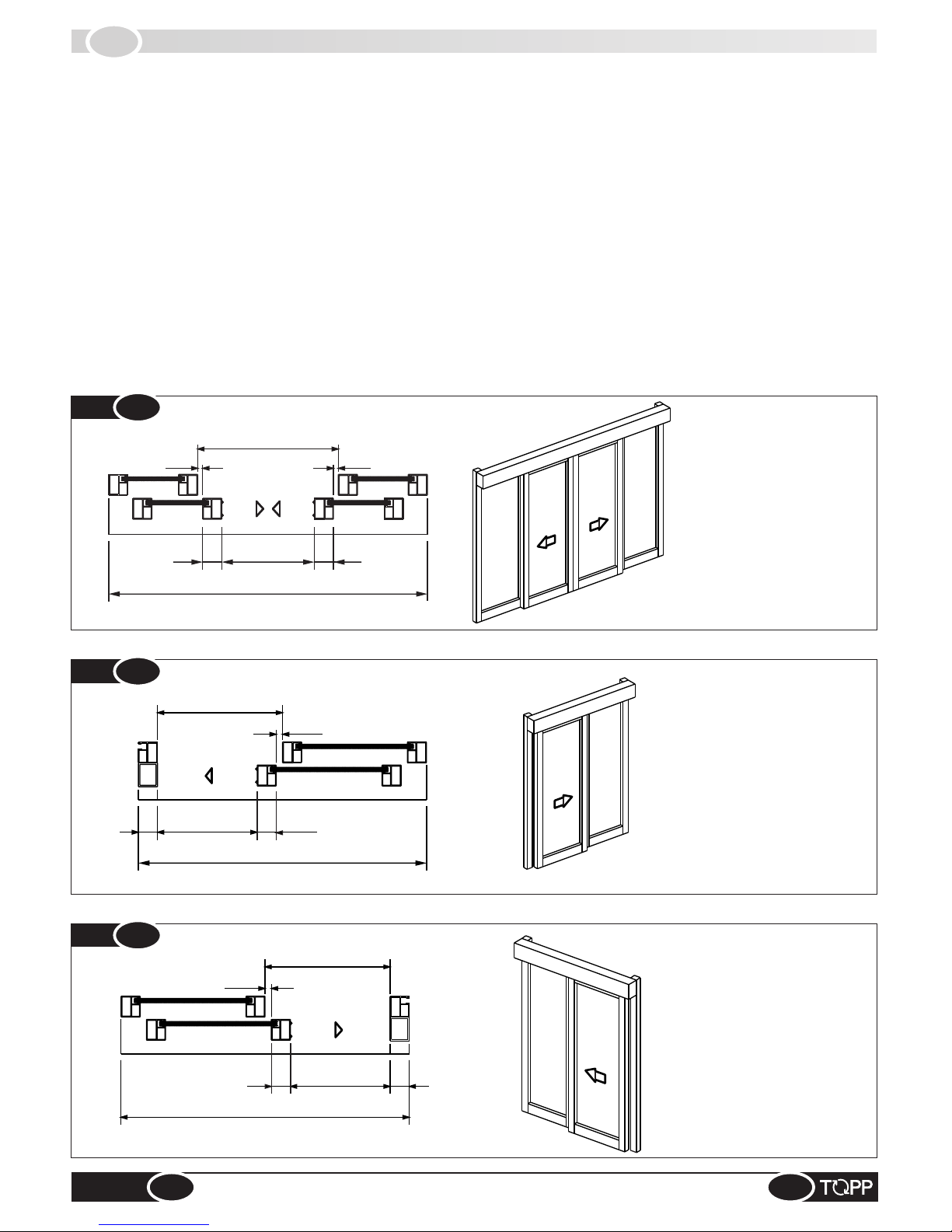
2.5
MODELS
Two models of automation are available:
% automation with 2 door panels (Fig.2) which allows a pair of door panels to glide simultaneously in opposite directions;
% automation with 1 door panels which allows a single door panel to glide in one direction; Fig.3 shows an application
with a single door that opens toward the right (seen from the front of the automation); Fig.4, shows a single door that
opens toward the left (seen from the front of the automation).
@ When order a single door panel application, always specify the direction of opening of the door, seen from the front
of the automation.
@ To comply with the safety regulations, the glide of the door panel VPA must be less than the door opening width VL.
The glide of the door panel VPA is equal to VL when the upright on the door does not have any roundings and/or
protrusions that could cause a shearing effect.
VPA*
VL
LT/LC
25 25
75
75
VPA*
VL
LT/LC
25
75
75
VPA*
LT/LC
25
75
75
LT/LC
LT/
LC
PC
BP
PC
BP
PC
PC
LT
/
LC
LT/
LC
PC
BP
BP
PC
Fig.
2
Fig.
3
Fig.
4
7
VPA = net doorway width
VL = gross opening
LT/LC = automation length /
casing length
BP = rail + runner on the floor
PC = electric wire raceway
1 RIGHT DOOR PANEL
1 LEFT DOOR PANEL
2 DOOR PANELS
VPA = net doorway width
VL = gross opening
LT/LC = automation length /
casing length
BP = rail + runner on the floor
PC = electric wire raceway
VPA = net doorway width
VL = gross opening
LT/LC = automation length /
casing length
BP = rail + runner on the floor
PC = electric wire raceway
INSTRUCTIONS FOR INSTALLATION AND USE
EN
K140
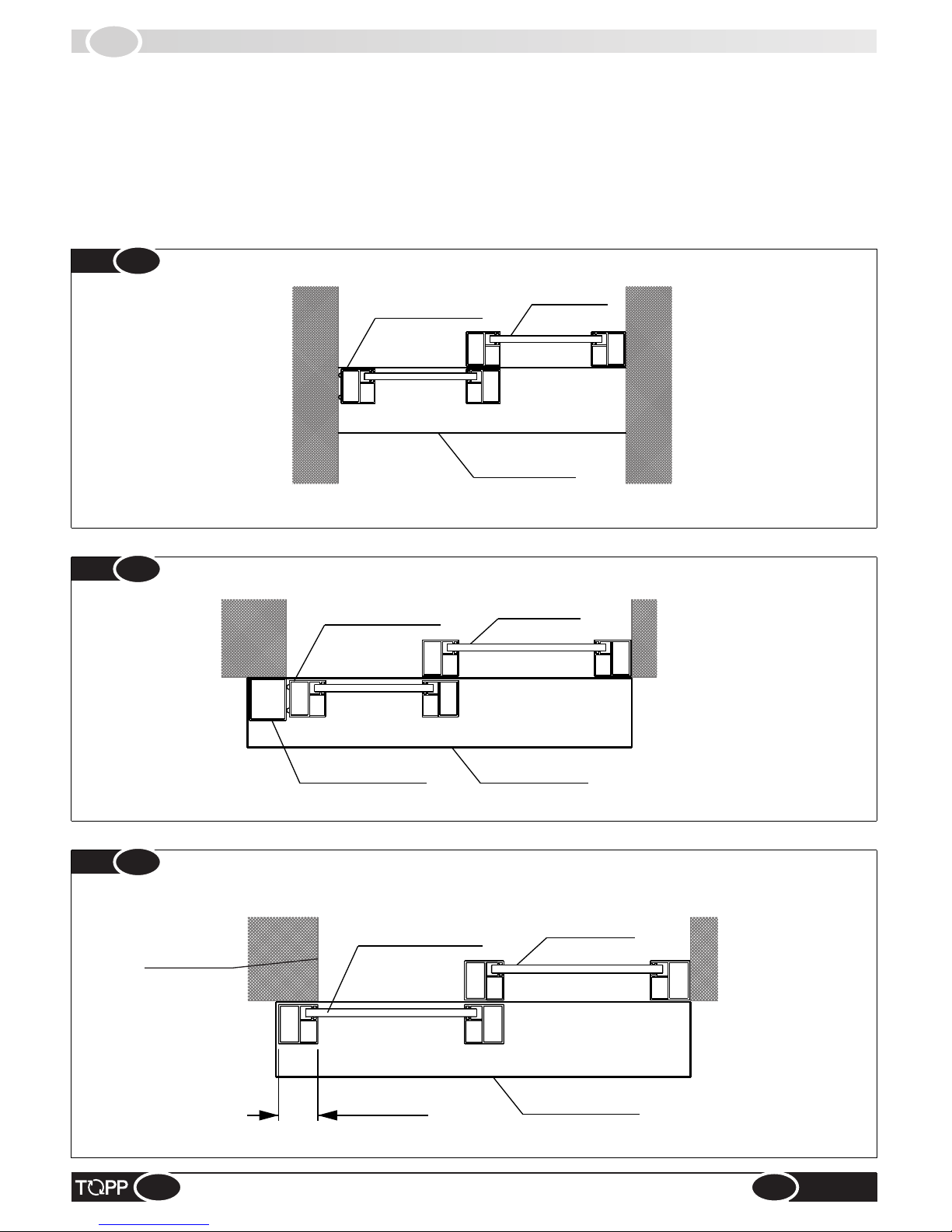
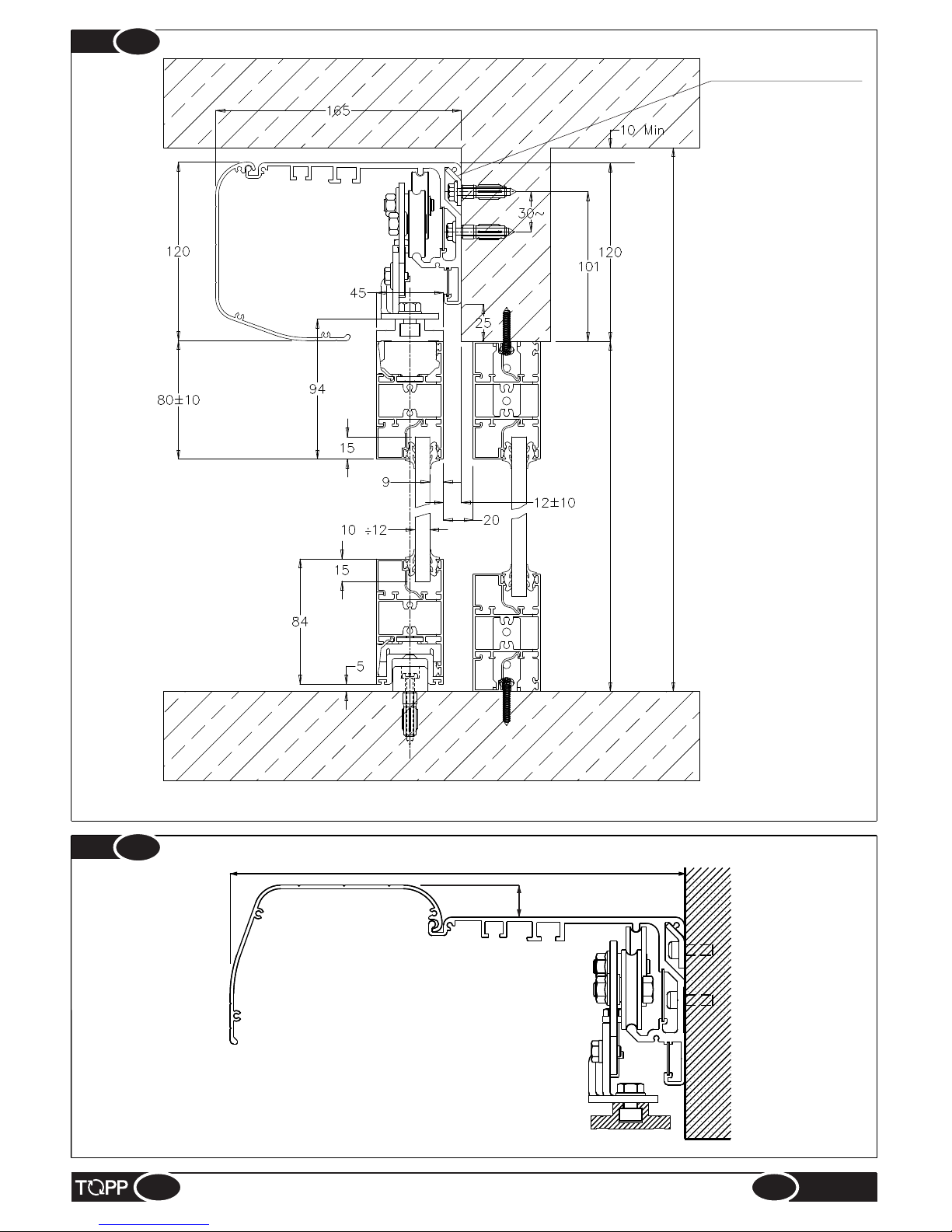
2.6
DESCRIPTION OF PARTS AND DIMENSIONS
To reduce the hazard of getting the fingers caught, we recommend the assembly type as shown in Fig.5a and Fig.5b,
where the wall and/or tubular frame act as a jamb and stop the door panel.
Alternatively, proceed as shown in Fig.6 overlapping the end of the wall (and/or closing upright) with the profile of the
sliding panel and moderating the closing speed and speed of approach of the door.
@ In some countries the laws forbid this type of assembly as there is a possible risk of getting the fingers caught.
Fixed door
panel
Sliding door panel
Automation
Fixed door panel
Sliding door panel
Tubular jamb
Automation
Fixed door panel
Sliding door panel
Overlap
Automation
Fig.
5a
Fig.
5b
Fig.
6
8
Wall end
INSTRUCTIONS FOR INSTALLATION AND USE
EN
K140
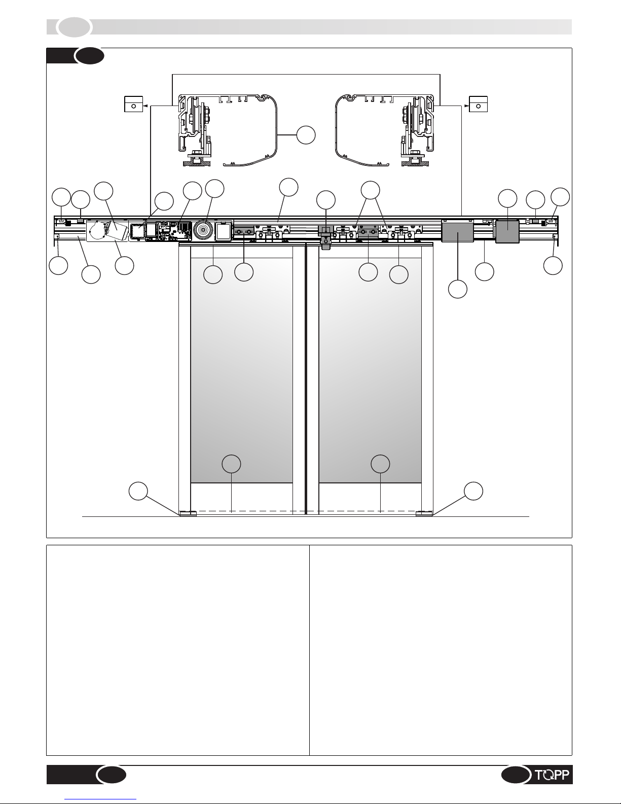
2.7
DESCRIPTION OF PARTS AND DIMENSIONS
1 -
2 -
3 -
4 -
5 -
6 -
7 -
Main crossbar
Carriage with double wheel
Adapter for door panel suspension
Casing
Toothed transmission belt
18 - Door stop
11 -
Door lock with manual release
12 -
13 -
Photocell control unit
14 -
15 -
Rail for door guide
16 -
Plastic runner on floor
17 -
Wire raceway
8 -
9 -
10 -
Door panel drive bracket
Belt transmission with pulley and encoder
Low voltage transformer
Electronic control circuit
Lateral case fastener
Emergency battery
Gearmotor
Metal motor module19 -
Crossbar supporting hooks
9
INSTRUCTIONS FOR INSTALLATION AND USE
5
Fig.
7
20 - Logline
15
15
16
16
13
4
4
9
6
7
6
3
19
3
2
18
18
12
11
8
10
14
1
20
EN
K140
17
17
255
20
Fig.
9
10
INSTRUCTIONS FOR INSTALLATION AND USE
EN
K140
Ceiling height
Opening door height
Fig.
8
Crossbar supporting
bracket

IT
INSTALLATION
3
3.1
GENERAL RECOMMENDATIONS
The automation must be installed exclusively by competent, qualified technical personnel in possession of the
technical requisites foreseen by the legislation in force in the country of installation.
& Do not install the automation on the external wall of the building, subject to atmospheric agents (rain, snow, etc.).
& Do not use the automation in environments with a potentially explosive atmosphere.
& The zones in which there may be a danger of crushing, shearing, conveyance or other risks are signaled and
protected by means of special electronic safety devices, safety stops or barriers. These devices must be installed
depending on the environment and type of use and operating logic of the product.
& The forces developed by the complete system during operation must respect the regulations in force in the country of
installation; if this is not possible, protect and signal by means of electronic safety devices the zones affected by those
forces.
& Before installing the automation, verify that the structure to be automated is stable, sturdy and able to withstand the
weight of the automation and, if necessary, take steps to ensure that it is. Topp srl is not liable for failure to comply with the
rules of good workmanship in the construction of the door panels to motorize, or for any distortions that may develop with
use of the device.
(Model with two panels) To install the crossbar, proceed as follows:
% Mark the surface where the automation will be fastened at the center of the opening VL that is also the center of the
crossbar;
% Decide the position of fastening the crossbar supporting brackets, referring to the measurements shown in Fig.8;
@ If the floor is not perfectly flat, decide the position of the supporting brackets referring to the highest point of the floor.
% Fasten the crossbar supporting brackets to the wall using self-drilling/sell-tapping screws type d5.5 or d6,3;
% Remove the cover on the casing;
% Install the crossbar and make sure it is aligned;
% Fasten the crossbar to the wall with 3 self-tapping screws type d6.3 for every meter of crossbar and paying careful
attention not to damage the gliding base of the carriages with the drill spindle. In case of damage it will be necessary to
replace the entire crossbar;
% After fastening the crossbar clean the glide zone soiled by drilling residues.
3.2
INSTALLING THE CROSSBAR
((Model with 1 panel) To install the crossbar, proceed as follows:
% Mark the surface where the automation will be fastened at the center of the crossbar that corresponds:
Ÿ to the line of the wall end on the left of the doorway for application of 1 door panel with the opening toward the left;
Ÿ to the line of the wall end on the left of the doorway for application of 1 door panel with the opening toward the right;
% Decide the position of fastening the crossbar supporting brackets, referring to the measurements shown in Fig.8;
@ If the floor is not perfectly flat, decide the position of the supporting brackets referring to the highest point of the floor.
% Remove the cover on the casing;
% Fasten the crossbar supporting brackets to the wall using self-drilling/sell-tapping screws type d5.5 or d6,3.
% Install the crossbar and make sure it is aligned;
% Fasten the crossbar to the wall with 3 self-tapping screws type d6.3 for every meter of crossbar and paying careful
attention not to damage the gliding base of the carriages with the drill spindle. In case of damage it will be necessary to
replace the entire crossbar.
% After fastening the crossbar clean the glide zone soiled by drilling residues.
11
INSTRUCTIONS FOR INSTALLATION AND USE
EN
K140
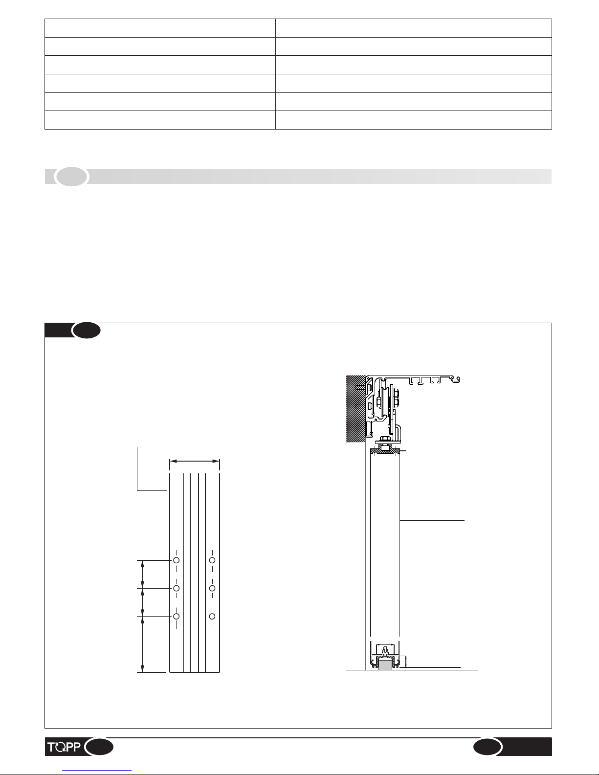
3.3
INSTALLING THE ADAPTER AND RAIL
70÷80
40
Door panel
40
45
Adapter
% Cut the adapter and rail to the measurement of the finished door width, removing another 2 mm from the jamb sider;
% Make sure the upper part of the panel crossbar is reinforced at the base (minimum thickness 3 mm);
% Drill the adapter and rail starting at about 70/80 mm from the end;
@ The number of fastening holes will depend on the size and weight of the door.
% Mark the fastening points on the door using the adapter and rail as a templat;
% Drill the door panel at the top and fasten the adapter using cylindrical M6 screws or cylindrical self-tapping d5.5 screws
depending on the type of material;
% Drill the door at the bottom and fasten the rail using flared self-tapping cylindrical screws diam. 4.8.
20
31
Rail
Fig.
10
12
IRON
2 mm (with lesser thickness use threaded rivets)
3 mm (with lesser thickness use threaded rivets)
100 mm
50 mm
Minimum thickness
Materials of the fastening surface
ALUMINUM
SOLID WOOD
REINFORCED CONCRETE
110 mm (with lesser thickness use chemical bolts)
PERFORATED CONCRETE
INSTRUCTIONS FOR INSTALLATION AND USE
EN
K140
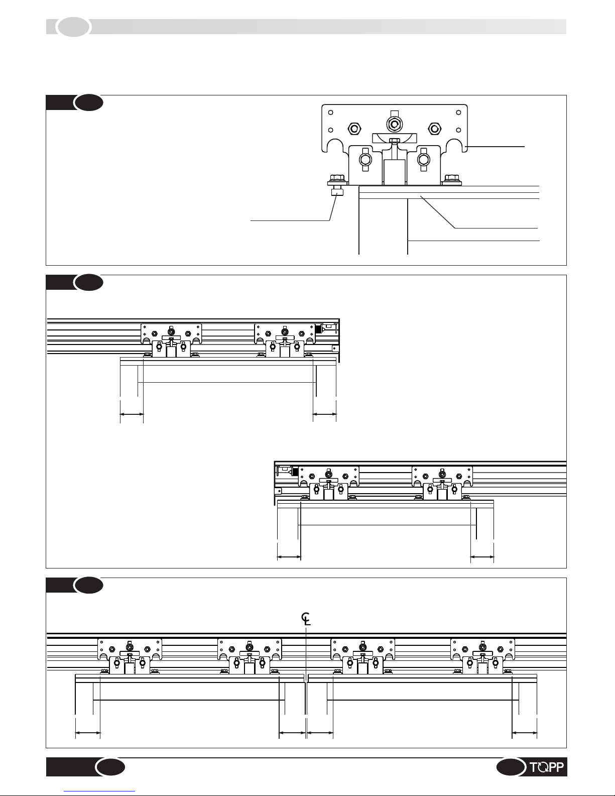
Install the carriages on the adapter as shown in the figure.
@ Make sure the carriages are installed correctly and are aligned with each other, with the adapter and with the
crossbar.
Standard adapter
Fastening nut
Carriage
70 70
7070
15÷70
70 70
15÷70
3.4
INSTALLING THE CARRIAGESON THE DOOR
Fig.
11
Installation by insertion
Fig.
12
Single door panel, opening toward the left
Single door panel, opening toward the right
Fig.
13
Double door panel, simultaneous opening toward the right and left
13
INSTRUCTIONS FOR INSTALLATION AND USE
EN
K140
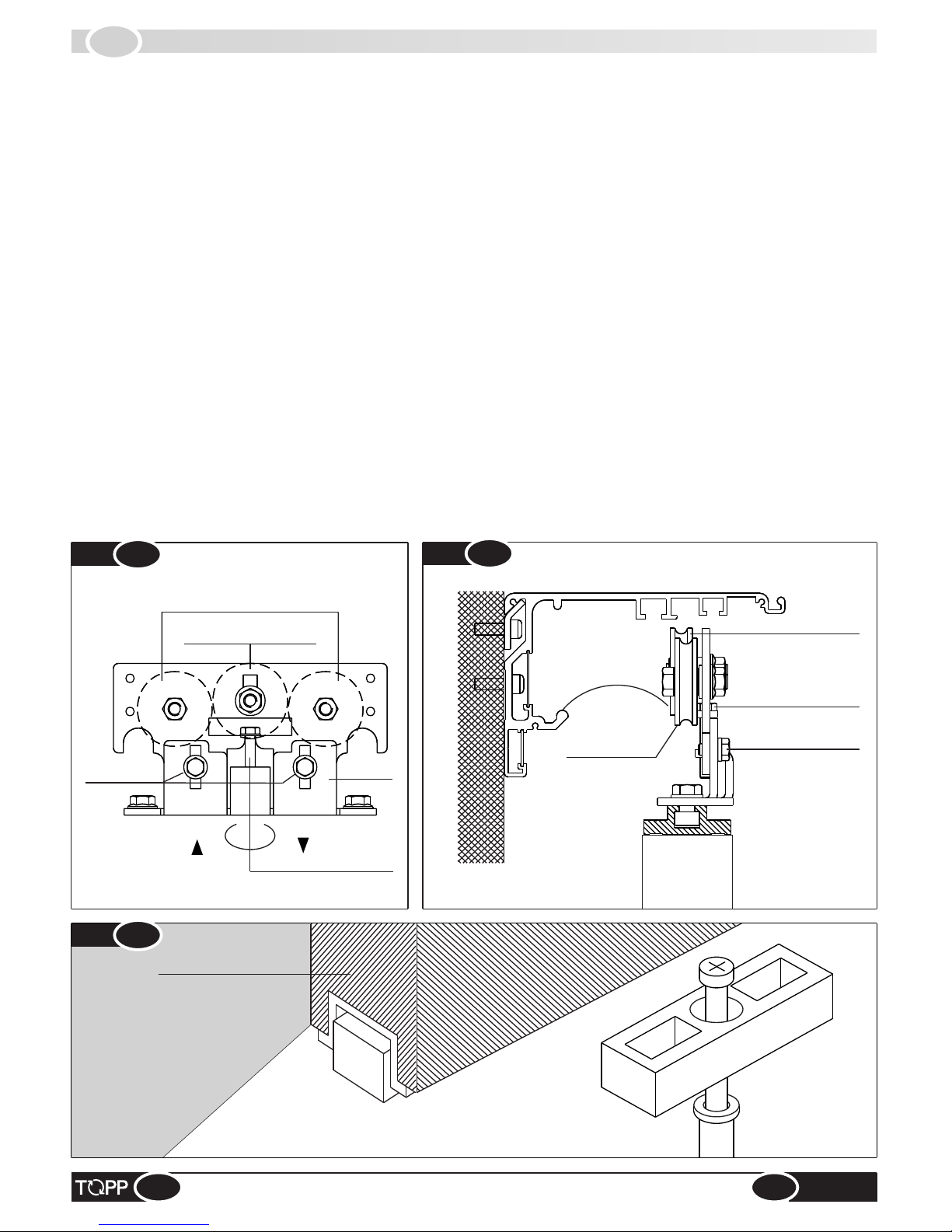
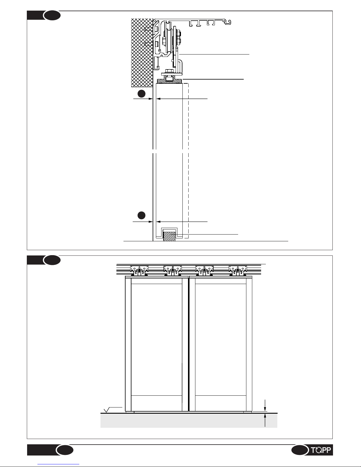
3.5
FASTENING AND ADJUSTMENT OF THE SLIDING PANELS
To fasten the sliding panels to the crossbar, proceed as follows:
% Lower the anti-derailing wheels of the carriages (Fig.14);
% Bring the panels to the crossbar and make sure the gliding base of the carriages is clean and free of any scraps;
% Fasten the door panel to the crossbar by raising it slightly and hooking it first on one side and then on the other, or both
sides at once (Fig.15);
% Loosen the fastening screws on the carriages and insert the no. 10 fixed wrench in the height adjustment screw on the
carriage and turn it to the left or right so that the door panel is about 5 mm off the floor (height for the standard runner);
% Determine the distance “A” for adjustment of the door panel (Fig. 17);
@ If an air seal brush must be installed between the sliding panel and the upright or wall, adjust the panel so that there is
a space of about 1 mm between it and the brush along the entire length;
% Fasten the runner to the floor at point “A” using the anchor bolt and self-tapping screw d 6x70 contained in the hardware
package (Fig.16).
% Adjust the distance “A” (Fig.17) by loosening the two screws that hold the lower bracket of the carriage to the adapter.
The holes on the brackets are in slot form to permit movement of the door by about 18 mm.
% Before tightening the screws make sure the carriages are aligned with each other and with the crossbar.
% Adjust the height of the sliding panels (Fig.18) using the special adjustment screws on the carriages (Fig.17). After
performing this operation, tighten the screws on the load-bearing wheels and raise the anti-derailing wheel.
@ Using the height adjustment screws on the carriages you can raise or lower the door by ±10mm (with the crossbar
installed on the basis of the measurements shown in Fig.8).
Load-bearing
wheels
Anti-derailing wheels
Height adjustment
Anti-derailing wheels
LEFT
Load-bearing wheels
Fastening screw
Adjustment screw
Carrello
RIGHT
Rear part of door panel
Fig.
15
Fig.
14
Fig.
16
14
Carriage Carriage
fastening screwfastening screw
Carriage
fastening screw
INSTRUCTIONS FOR INSTALLATION AND USE
EN
K140
Lower carriage bracket
Standard adapter
Runner on floor
A
A
Fig.
17
LPF
Fig.
18
5
15
INSTRUCTIONS FOR INSTALLATION AND USE
EN
K140
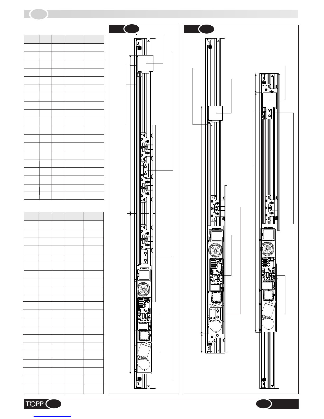
3.6
INSTALLING THE MOTOR MODULE, BELT TRANSMISSION, BELT,LOGLINE
2 DOOR PANELS
MOTOR MODULE
Lower belt bracket – front carriage – panel opening toward the right
Upper belt bracket – front carriage – panel opening toward the left
BELT TRANSMISSION
BELT TENSION ADJUSTMENT
MOTOR MODULE
1 RIGHT DOOR PANEL
Lower belt bracket – front carriage – panel opening toward the right
BELT TRANSMISSION
1 LEFT DOOR PANEL
MOTOR MODULE
Upper belt bracket – front carriage – panel opening toward the left
BELT TRANSMISSION
BELT TENSION ADJUSTMENT
BELT TENSION ADJUSTMENT
K140 - model with 2 door
panels (Fig.19)
K140 - model with
1 door panel (Fig.20)
16
INSTRUCTIONS FOR INSTALLATION AND USE
2700
1760
1760
2 x 3504
2800
1812 1812
2 x 3608
1000
876
876
2 x 1736
1100
928
928
2 x 1840
1200
980
980
2 x 1944
1300
1032
1032
2 x 2048
1400
1084
1084
2 x 2152
1500
1136
1136
2 x 2256
1600
1188
1188
2 x 2360
1700
1240
1240
2 x 2464
1800
1292 1292 2 x 2568
1900
1344
1344
2 x 2672
2000
1396
1396
2 x 2776
2100
1448
1448
2 x 2880
2200
1500
1500
2 x 2984
2300
1552
1552
2 x 3088
2400
1604
1604
2 x 3192
2500
1656
1656
2 x 3296
2600
1708
1708
2 x 3400
VPA
A
B
L Belt
L Logline
1700
120
1994
1 x 3976
1800
120
2098
1 x 4184
1900
120
2202
1 x 4392
2000
120
2306
1 x 4600
2100
120
2410
1 x 4808
2200
120
2514
1 x 5016
2300
120
2618
1 x 5224
2400
120
2722
1 x 5432
2500
120
2826
1 x 5640
2600
120
2930
1 x 5848
2700
120
3034
1 x 6056
2800
120
3138
1 x 6264
1000
120
1266
1 x 2520
1100
120
1370
1 x 2728
1200
120
1474
1 x 2936
1300
120
1578
1 x 3144
1400
120
1682
1 x 3352
1500
120
1786
1 x 3560
1600
120
1890
1 x 3768
VPA A
800
120
1058
1 x 2104
900 120
1162
1 x 2312
VPA
A
B
L Belt
L Logline
942
1046
1150
1254
1358
1462
1566
1670
1774
1878
1982
2086
2190
2294
2398
2502
2606
2710
2814
248
352
456
560
664
768
872
976
1080
1184
1288
1392
1496
1600
1704
1808
1912
2016
2120
2224
2328
C
L
B
B
A
A
B
Fig.
19
Fig.
20
A
EN
K140
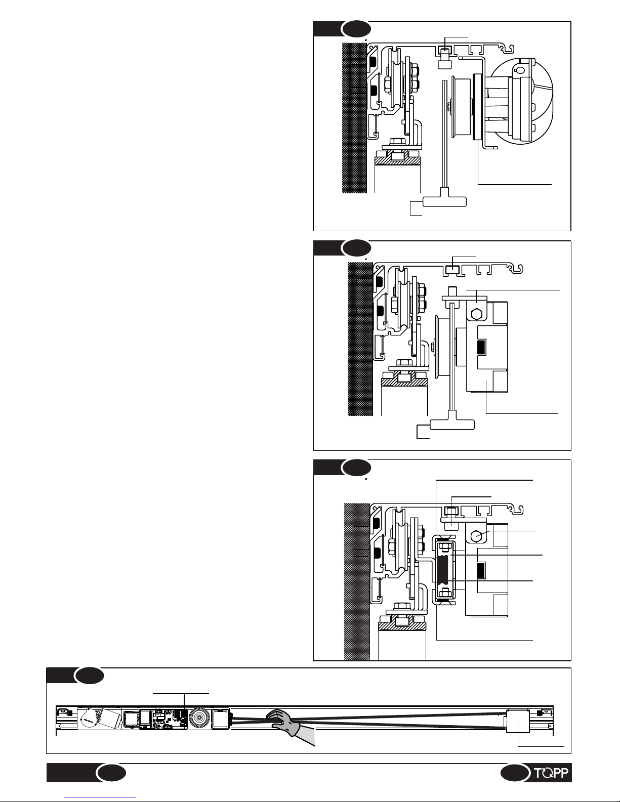
Before installing the motor module, belt transmission and
belt on the crossbar, prepare and install the wires
necessary for the electrical connections and make sure the
carriages, door panels and runners on the floor have been
fully adjusted and positioned.
Installing the motor module (Fig.21):
% Mark the reference measurements on the crossbar using
the tables on page 16;
% Loosen the two VTF screws on the crossbar for fastening
the motor module;
% Fit the motor module with the slots provided for fastening
in the VTF screws, check the reference mark on the
crossbar once more and tighten the VTF screws.
Installing the belt transmission (Fig.22):
% Mark the reference measurements on the crossbar using
the tables on page 16;
% Remove the two VTF screws on the crossbar for
fastening the belt transmission;
% Fit the transmission with the specific fastening holes in
the VTF screws and tighten them;
% Adjust the position of the belt tension adjustment on the
crossbar.
Installing the transmission belt (Fig.23):
% Install the transmission belt on the motor and
transmission pulley making sure the belt junction
brackets are positioned as shown in Fig.23. (Upper
bracket for door opening to the left, lower bracket for door
opening to the right).
% Slightly loosen screws “A” on the tension adjustment,
take the belt transmission to the end of its run and tighten
screws “A”.
% To tighten the belt, loosen screws “B” on the transmission
and turn screw “C” to obtain the proper belt tension.To
check the tension, with the handshake bring the two
edges of the belt as shown in Figure 23a.The tension is
enough if there is some resistance before the contact of
the two edges.
% Tighten screws “B” after checking that the transmission is
aligned with the crossbar.
No. 6 hexagonal wrench
Motor module
No. 6 hexagonal wrench
Belt transmission
Belt tension adjustment
A - B
Lower belt bracket
Belt
Upper belt bracket
Pulley
C
Fig.
23
17
INSTRUCTIONS FOR INSTALLATION AND USE
Fig.
23a
belt trasmission
Motor module
EN
K140
VTF
VTF
Fig.
21
Fig.
22

3.7
FASTENING DOOR DRIVE BRACKETSE
2 DOORS – simultaneous opening toward the right and left
DOOR OPENING TO RIGHT DOOR OPENING TO LEFT
M6x8 screws
M6x10 screws
Upper belt bracket
M6x8 screws
M6x10 screws
Upper belt bracket
Left front door carriage
Right front door carriage
Horizontal adjustment slots
Door drive bracket
Horizontal adjustment slots
Door drive bracket
C
L
Fig.
24
18
INSTRUCTIONS FOR INSTALLATION AND USE
EN
K140

1 LEFT DOOR – opening toward the left
1 RIGHT DOOR – opening toward the right
Front door carriage
Horizontal adjustment slots
Screws M6x8
Screws M6x10
Lower belt bracket
Door drive bracket
M6x8 screws
M6x10 screws
Upper belt bracket
Front door carriage
Horizontal adjustment slots
Door drive bracket
Fig.
25
Fig.
26
19
INSTRUCTIONS FOR INSTALLATION AND USE
EN
K140
EN
K140

3.8
INSTALLING THE DOOR BLOCK
Right door front carriage
Door block with manual
release incorporated
Front carriage
Front carriage
Door block with manual
release incorporated
Door block with manual
release incorporated
2 DOOR PANELS
1 RIGHT DOOR PANEL
1 LEFT DOOR PANEL
Carriage block fastener
Manual release
Carriage block fastener
Fastening screw
During installation, make sure that when the door is closed with the block on, it must be possible to open the door manually
by at least 2-3 mm. This tolerance is necessary to enable the block to be released without difficulty.
Fig.
27
Fig.
28
Fig.
29
Fig.
30
To release and open the door, push the manual release
lever under the casing forward and, at the same time, pull
the door with your hand until it opens.
Fig.
31
20
INSTRUCTIONS FOR INSTALLATION AND USE
EN
K140

3.9
INSTALLING THE CASING
21
INSTRUCTIONS FOR INSTALLATION AND USE
antivibration
felt
M3,5x9,5 screws for
fastening casing
A
Fig.
32
Fasten the lateral caps on the beam using 3 screws type TSP d3.5x9.5 for each cap, supplied in the hardware package.
Apply an antivibration felt strip every 300mm along the beam (Fig.32 Ref.1).
Fit the upper part of the casing in its housing on top of the beam, holding it in a tilted position at a 30° angle and insert it until
it is flush (Fig.32 Ref.2).
Fasten the casing to the beam using two more screws type TSP d3.5x9.5 (Fig.32 Ref.3).
If it should not be possible to fasten the casing from the side, proceed as follows:
% Drill symmetrical holes in the casing cover using a suitable drill with a Ø6.5 bit for aluminum, with the measurements
and position indicated in Fig.32 Ref.4
% Fasten the casing to the beam using the two screws type TCEI M5x10.
4
12mm
Ø6.5
1
2
3
M5x10 screws for
fastening casing
EN
K140
Rating place and “CE” marking

4.1
GENERAL RECOMMENDATIONS
IT
ELECTRICAL CONNECTION
4
Electrical connection of the automation must be made exclusively by qualified technical personnel in possession of
the professional requisites foreseen by the laws in the country of installation, who must issue the client a certificate
of conformity of the connection and/or installation made.
& Whatever type of electrical material is used for connection (plug, cord, terminals, etc.), it must be suitable for the use,
with the “CE” seal of approval and must comply with the requisites foreseen by the laws in force in the country of
installation. For the wiring, use cables with double insulation up to the immediate vicinity of the connectors.
& The electrical power line to which the control unit is connected must comply with the requisites foreseen by the laws in
force in the country of installation, and must comply with the technical requisites listed in table 1 and on the “CE” rating
plate.
& The mains to which the device will be connected must be equipped with a safety circuit breaker with contact opening
of at least 3mm. These devices must be installed in the power system in conformity with the requisites foreseen by the
legislation in force in the country of installation.
The installation must include a ground wire longer than the power cord so that, in case of traction, the ground wire is the
last to stretch.
& We recommend the following types of power cables: H05VV-F 3X0.75, H05RN-F 3X0.75.For the analogue switch
cable we recommend using a multipole 8 x 0.5 cable type LI-YY, and for the digital switch 4x0.5 LI-YY ( cable ‘shielding’
should only be used for cable lengths in excess of 20 meters).
& Before making electrical connection of the automation, make sure the power cord has not been damaged.
& The hole drilled on the profile for passage of the power cord must be made without any rough or sharp edges or sharp
corners that could damage the wire.
22
4.2
ELECTRICAL CONNECTION
INSTRUCTIONS FOR INSTALLATION AND USE
- Before fastening the door to the wall, drill a hole on the bottom of the crossbar (or more than one if you need to connect
accessories) where the power cables emerge from the wall. The holes should be 10 mm in diameter, fitted with the rubber
cable sleeves supplied.
- If the raceway has not already been installed, cut it to size in accordance with the tables in paragraph 3.6, and drill it as
shown on figure 1 by using an aluminium drill bit having diameter 6.5mm.
Then fasten it to the crossbar using the screws and nuts supplied, as shown in figure 2.
The spacing between nut and nut should be 400 mm.
- Make sure there is a switch with a contact opening of at least 3 mm between the automation and the mains, for omnipolar
disconnection of power.
- Thread the power cable through the cable sleeve as shown in figure 3.
Pass the cable towards the right along the track of the crossbeam, using the plates provided to keep the cables in their
housing. Make them come out near the right end-of-travel stop.
- Make sure the cables are securely fastened, possibly using special clamps to keep them in order.
- Pass the cables in the front section over the belt/encoder transmission, using the groove on the crossbar, and inside the
special raceway.
Insert the power supply cable into the dedicated band and secure it using the bolt provided. Connect it to the terminal after
having stripped the cable;
- Connect the cables of any accessories as described in the appropriate figures (see from fig. 35 to fig. 40)
Make sure that all the cables are inside the duct and that they cannot come into contact with moving parts once positioned.
During installation, make sure that the conductor cables are secured by an additional attachment near the terminals or
electrical connections, i.e. using bands.
Make sure that the cables are stripped near the terminals.
EN
K140

4.3
ELECTRONIC CIRCUIT BOARD
1. Infrared sensor input,
microwave sensors,
photocells, door opening
safety guard
2. Input for program selector
input with knob
3. Input for lateral guards,
antipanic device and test
sensors
4. Digital switch input
5. Input for air curtain, lamp,
key switch, emergency key,
smoke detectors
6. Emergency battery system
input
7. Gearmotor input
8. Door block 1 input
9. Door block 2 input
(pharmacy)
10. Transformer input
11. Lighted display
12. Encoder cord input
13. DOWN key
14. ENTER key
Fig.
33
23
INSTRUCTIONS FOR INSTALLATION AND USE
Figure 3
Figure 2
Hole ø 10 mm
with rubber cable
sleeves
Fig.
33
EN
K140
Figure 1
Screw M6x20
M6 Nut
Raceway
Spring
Ds2
Ds3
Ds4
10
9
8
5
3
1
2
4
12
PC
don’t touch
14
1
1
13
6
7
Ø6.5
30mm
400mm
400mm
400mm
400mm
30mm

4.4
PRE-WIRED ELECTRIC CONNECTIONS
TransformerTransformerTransformer
Fig.
34
24
INSTRUCTIONS FOR INSTALLATION AND USE
Circuit
Red
Blue
Black
BEL
T
TRANSMISSION
ENCODER
MOTOR
BATTER
Y
EN
K140
Red
1. SMOKE
FIRE SYSTEM
2. EMERGENCY
3. CLOSURE
KEY
4. OPENING
KEY
5. LAMP
6. AIR
CURTAINS
7. GND
8. 24V*
17. INTERNAL
SECURITY
18. INTERNAL
RADAR
19. GND
20. GND
21. EXTERNAL
SECURITY
22. EXTERNAL
RADAR
23. GND
24. 24V
Ÿ 24V
Ÿ GND
Ÿ SIGNAL A
Ÿ GND (shield)
Ÿ SIGNAL B
* Unregolated
25. RESET (NEAR)
26. OPEN
27. PARTIAL
28. EXIT ONLY
29. ENTER ONLY
30. CLOSED
31. GND
32. 24V
9. TEST+
10. TEST+
11. GND
12. ANTIPANIC
DEVICE
13. LATERAL
SAFETY 2
14. LATERAL
SAFETY 1
15. GND
16. 24V
F
N
1 9 17 25
2 10 18 26
3 11 19 27
4 12 20 28
5 13 21 29
6 14 22 30
7 15 23 31
8 16 24 32

START
2 Sensors
activation
1 Activation/Safety
Sensor
+1 Activation Sensor
+ Photocells
2 Activation/Safety
sensors
+1 Lateral sensor
1 Activation/Safety
sensor
+1 Activation Sensor
+ 2 Lateral sensors
+ Photocells
2 Activation/Safety
sensors
+ 2 Lateral sensors
WITHOUT IS5
LATERAL
2 Activation sensors
+
1 Lateral sensor
+ Photocells
2 Activation sensors
+ 2 Lateral sensor
+ Photocells
2 Sensors on
passenger cab
+
1 Lateral sensor
2 Sensors on
passenger cab
2 Sensors on
passenger cab
+
2 Lateral sensor
1 Activation/Safety
sensor
+1 Activation Sensor
+
1 Lateral sensor
+ Photocells
ONLY ACTIVATION
WITH IS5
LATERAL
ACTIVATION WITH
SAFETY SENSORS
ACTIVATION WITH SAFETY
SENSORS MONITORED
2 Activation/Safety
Sensors
2 Activation/Safety
Sensors +Photocells
A
M
C
D
E
G
I
F H
N
25
IT
K140
25
EN
K140
ELECTRICAL WIRING DIAGRAM (FLOW CHART)
4.5
Fig.
35
B
L
O
INSTRUCTIONS FOR INSTALLATION AND USE
Optex
Hotron
Mo Mh
Optex
Hotron
No Nh
Optex
Hotron
Oo Oh

4.6
CONNECTION OF DETECTION SENSORS
26
EN
K140
INSTRUCTIONS FOR INSTALLATION AND USE
¬Dig i tal pr o gra m s witc h m enu: PAR A METE RS> OT H ER
PARAMETERS> SAFETY SENSOR LOGIC: N.C. WITHOUT TEST
Or program parameter 9 with the dot
N.C. SIC
COM. SIC
NO ATT.
COM. ATT.
GND
+24V
N.C. SIC
COM. SIC
NO ATT.
COM. ATT.
GND
+24V
green/blackgreen/blackgreen/black
white/blackwhite/blackwhite/black
yellowyellowyellow
whitewhitewhite
greygreygrey
greygreygrey
Fig.
B
17
18
19
12 20
13 21
14 22
15 23
24
17
18
17
18
19
12 20
13 21
14 22
15 23
24
GND
+24V
greygreygrey
greygreygrey
whitewhitewhite
yellowyellowyellow
greygreygrey
greygreygrey
18
20
23
24
24 23
20
22
ACTIVATION
N.O.
GND
+24V
COM
Fig.
ACTIVATION
N.O.
COM
whitewhitewhite
yellowyellowyellow
A
19
19
20
20
21
22
23
23
24
24
¬Digital program switch menu: PARAMETERS> OTHER PARAMETERS>
SAFETY SENSOR LOGIC: N.C. WITHOUT TEST
Or program parameter 9 with the dot
IS2 INTERNAL ACTIVATION/SAFETY
SENSOR
IS2 EXTERNAL ACTIVATION/SAFETY
SENSOR
Is1 INTERNAL ACTIVATION/SAFETY
SENSOR
IS1 EXTERNAL ACTIVATION
SENSOR
green/blackgreen/blackgreen/black
white/blackwhite/blackwhite/black
yellowyellowyellow
whitewhitewhite
greygreygrey
greygreygrey

27
EN
K140
INSTRUCTIONS FOR INSTALLATION AND USE
¬Digital program switch menu:
PARAMETERS>OTHER PARAMETERS>
SAFETY SENSOR LOGIC: N.C. WITH TEST
Or program parameter 9 without the dot
F1-F2
PHOTOCELLS
CIRCUIT
RX1 - TX1 = First beam
RX2 - TX2 = Second beam
9
18
19
20
21
22
15 23
24
RX1RX1RX1
COM RXCOM RXCOM RX
RX2RX2RX2
TEST -TEST -TEST -
TEST +TEST +TEST +
TX1TX1TX1
COM TXCOM TXCOM TX
OUTOUTOUT
OUTOUTOUT
RX1RX1RX1
COM RXCOM RXCOM RX
RX2RX2RX2
TX1TX1TX1
RX1RX1RX1 RX2RX2RX2
TX1TX1TX1 TX2TX2TX2
redredred
whitewhitewhite
whitewhitewhite
TEST +TEST +TEST +
OUTOUTOUT
GNDGNDGND
TEST -TEST -TEST -
OUTOUTOUT
COM TXCOM TXCOM TX
redredred
Tx2Tx2Tx2
24V24V24V
ACTIVATION
GND
+24V
N.O.
COM
ACTIVATION
GND
+24V
N.O.
COM
yellowyellowyellow
whitewhitewhite
greygreygrey
greygreygrey
Fig.
C
TEST-TEST-TEST-
TEST+TEST+TEST+
24V24V24V
GNDGNDGND
OUTOUTOUT
OUTOUTOUT
18
20
23
24
23
24
20
22
9
24
15
23
19
21
18
20
22
23
21
19
yellowyellowyellow
whitewhitewhite
greygreygrey
greygreygrey
IS1 EXTERNAL ACTIVATION
SENSOR
IS1 INTERNAL ACTIVATION
SENSOR

28
EN
K140
INSTRUCTIONS FOR INSTALLATION AND USE
¬Digital program switch menu:
PARAMETERS>OTHER PARAMETERS>
SAFETY SENSOR LOGIC: N.C. WITHOUT TEST
Or program parameter 9 with the dot
F1-F2
PHOTOCELLS
CIRCUIT
RX1 - TX1 = First beam
RX2 - TX2 = Second beam
IS1 EXTERNAL ACTIVATION
SENSOR
17
18
19
12 20
13 21
14 22
15 23
24
RX1RX1RX1
COM RXCOM RXCOM RX
RX2RX2RX2
TEST -TEST -TEST -
TEST +TEST +TEST +
TX1TX1TX1
COM TXCOM TXCOM TX
OUTOUTOUT
OUTOUTOUT
RX1RX1RX1
COM RXCOM RXCOM RX
RX2RX2RX2
TX1TX1TX1
RX1RX1RX1 RX2RX2RX2
TX1TX1TX1 TX2TX2TX2
redredred
whitewhitewhite
TEST +TEST +TEST +
OUTOUTOUT
GNDGNDGND
TEST -TEST -TEST -
COM TXCOM TXCOM TX
redredred
Tx2Tx2Tx2
24V24V24V
GND
+24V
COM
N.C.
GND
+24V
N.O.
COM
N.O.
COM
ACT.
SIC.
ACT.
green/blackgreen/blackgreen/black
yellowyellowyellow
white/blackwhite/blackwhite/black
whitewhitewhite
whitewhitewhite
yellowyellowyellow
greygreygrey
greygreygrey
greygreygrey
24V24V24V
GNDGNDGND
OUTOUTOUT
OUTOUTOUT
OUTOUTOUT
whitewhitewhite
Fig.
D
17
19
18
20
20
23
22
24
23
24
greygreygrey
21
19
24
IS2 INTERNAL ACTIVATION/SAFETY
SENSOR

29
EN
K140
INSTRUCTIONS FOR INSTALLATION AND USE
17
18
11 19
12 20
13 21
14 22
15 23
16 24
GND
+24V
COM
N.C.
GND
+24V
N.O.
COM
N.O.
COM
ACT.
SIC.
ACT.
green/blackgreen/blackgreen/black
yellowyellowyellow
white/blackwhite/blackwhite/black
whitewhitewhite
whitewhitewhite
yellowyellowyellow
greygreygrey
greygreygrey
greygreygrey
TEST -TEST -TEST -
TX1TX1TX1
RX1RX1RX1
COM RXCOM RXCOM RX
RX2RX2RX2
TX1TX1TX1
RX1RX1RX1 RX2RX2RX2
TX1TX1TX1 TX2TX2TX2
TEST +TEST +TEST +
GNDGNDGND
TEST -TEST -TEST -
OUTOUTOUT
COM TXCOM TXCOM TX
redredred
Tx2Tx2Tx2
24V24V24V
GNDGNDGND
24V24V24V
OUTOUTOUT
OUTOUTOUT
+24V
GND
COM
+24V
GND
N.C.
COM
Fig.
E
OUTOUTOUT
redredred
whitewhitewhite
whitewhitewhite
24
24
23
23
22
20
20
greygreygrey
18
19
17
16
15
13
14
14
24
23
19
21
15
16
15
15
16
13
N.C.
F1-F2
PHOTOCELLS
CIRCUIT
Is5 LATERAL SENSOR 2 IS5 LATERAL SENSOR 1
RX1 - TX1 = First beam
Rx2 - TX2 = Second beam
IS1 EXTERNAL ACTIVATION
SENSOR
IS2 INTERNAL ACTIVATION/SAFETY
SENSOR
¬Digital program switch menu:
PARAMETERS>OTHER PARAMETERS> SAFETY SENSOR LOGIC: N.C. WITHOUT TEST
Or program parameter 9 with the dot

30
IT
K140
30
EN
K140
IS5 LATERAL SENSOR
INSTRUCTIONS FOR INSTALLATION AND USE
¬Digital program switch menu:
PARAMETERS>OTHER PARAMETERS>
SAFETY SENSOR LOGIC: N.C. WITHOUT TEST
Or program parameter 9 with the dot
IS2 EXTERNAL ACTIVATION/SAFETY
SENSOR
IS2 INTERNAL ACTIVATION/SAFETY
SENSOR
17
18
11 19
12 20
13 21
14 22
15 23
16 24
N.C.N.C.N.C.
24V24V24V
GNDGNDGND
Fig.
F
24V
GND
N.C.
COM
14
15
16
N.C. SIC
COM. SIC
NO ATT.
COM. ATT.
GND
+24V
N.C. SIC
COM. SIC
NO ATT.
COM. ATT.
GND
+24V
green/blackgreen/blackgreen/black
white/blackwhite/blackwhite/black
yellowyellowyellow
whitewhitewhite
greygreygrey
greygreygrey
17
18
19
19
20
20
21
22
23
23
24
24
green/blackgreen/blackgreen/black
white/blackwhite/blackwhite/black
yellowyellowyellow
whitewhitewhite
greygreygrey
greygreygrey

18
11 19
12 20
13 21
14 22
15 23
16 24
RX1RX1RX1
COM RXCOM RXCOM RX
RX2RX2RX2
TEST -TEST -TEST -
TEST +TEST +TEST +
TX1TX1TX1
COM TXCOM TXCOM TX
OUTOUTOUT
OUTOUTOUT
PHOTOCELLS
CIRCUIT
F1 - F2
RX1RX1RX1
COM RXCOM RXCOM RX
RX2RX2RX2
TX1TX1TX1
RX1RX1RX1 RX2RX2RX2
TX1TX1TX1 TX2TX2TX2
RX1 - TX1 = First beam
Rx2 - TX2 = Second Beam
whitewhitewhite
whitewhitewhite
TEST +TEST +TEST +
OUTOUTOUT
GNDGNDGND
TEST -TEST -TEST -
OUTOUTOUT
COM TXCOM TXCOM TX
redredred
Tx2Tx2Tx2
24V24V24V
ACTIVATION
GND
+24V
N.O.
COM
ACTIVATION
GND
+24V
N.O.
COM
¬ Digital program switch menu:
PARAMETERS>OTHER PARAMETERS>
SAFETY SENSOR LOGIC: N.C. WITHOUT TEST
Or program parameter 9 with the dot
yellowyellowyellow
whitewhitewhite
greygreygrey
greygreygrey
yellowyellowyellow
whitewhitewhite
greygreygrey
greygreygrey
24V
GND
N.C.
COM
Is5 LATERAL S.
Fig.
G
24V24V24V
GNDGNDGND
N.C.N.C.N.C.
Is1 INTERNAL ACTIVATION
SENSOR
Is1 EXTERNAL ACTIVATION
SENSOR
redredred
31
EN
K140
18
19
20
21
22
23
23
23
24
24
24
20
14
15
16
INSTRUCTIONS FOR INSTALLATION AND USE

17
18
11 19
12 20
13 21
14 22
15 23
16 24
¬ Digital program switch menu:
PARAMETERS>OTHER PARAMETERS>
SAFETY SENSOR LOGIC: N.C. WITHOUT TEST
Or program parameter 9 with the dot
24V
GND
N.C.
COM
24V
GND
N.C.
COM
IS5 S. LATERAL S. 2
IS5 LATERAL S. 1
Fig.
H
32
EN
K140
N.C. SIC
COM. SIC
NO ACT.
COM. ACT.
GND
+24V
N.C. SIC
COM. SIC
NO ACT.
COM. ACT.
GND
+24V
green/blackgreen/blackgreen/black
white/blackwhite/blackwhite/black
yellowyellowyellow
whitewhitewhite
greygreygrey
greygreygrey
IS2 INTERNAL ACTIVATION/SAFETY S.
IS2 EXTERNAL ACTIVATION/SAFETY S.
17
18
19
19
20
20
21
22
23
23
24
24
14
15
16
13
15
16
INSTRUCTIONS FOR INSTALLATION AND USE
green/blackgreen/blackgreen/black
white/blackwhite/blackwhite/black
yellowyellowyellow
whitewhitewhite
greygreygrey
greygreygrey

17
18
11 19
12 20
13 21
14 22
15 23
16 24
OUTOUTOUT
OUTOUTOUT
PHOTOCELLS
CIRCUIT
F1 - F2
RX1RX1RX1 RX2RX2RX2
TX1TX1TX1 TX2TX2TX2
RX1 - TX1 = First beam
Rx2 - TX2 = Second bam
TEST +TEST +TEST +
TEST -TEST -TEST -
OUTOUTOUT
COM TXCOM TXCOM TX
redredred
Tx2Tx2Tx2
24V24V24V
GNDGNDGND
24V24V24V
¬ Digital program switch menu:
PARAMETERS>OTHER PARAMETERS>SAFETY SENSOR LOGIC: N.C. WITHOUT TEST
Or program parameter 9 with the dot
24V
GND
N.C.
COM
IS5 LATERAL S.
Fig.
I
24V24V24V
GNDGNDGND
N.C.N.C.N.C.
33
EN
K140
redredred
whitewhitewhite
whitewhitewhite
GND
+24V
COM
N.C.
GND
+24V
N.O.
COM
N.O.
COM
ACT.
SIC.
ATT.
green/blackgreen/blackgreen/black
yellowyellowyellow
wite/blackwite/blackwite/black
whitewhitewhite
whitewhitewhite
yellowyellowyellow
greygreygrey
greygreygrey
greygreygrey
IS2 INTERNAL ACTIVATION/SAFETY S.
IS1 EXTERNAL ACTIVATION SENSOR
24
24
23
23
22
20
20
greygreygrey
18
19
17
14 15 16
OUTOUTOUT
19
21
2324
GNDGNDGND
RX1RX1RX1
COM RXCOM RXCOM RX
RX2RX2RX2
TX1TX1TX1
INSTRUCTIONS FOR INSTALLATION AND USE

18
11 19
12 20
13 21
14 22
15 23
16 24
RX1RX1RX1
COM RXCOM RXCOM RX
RX2RX2RX2
TEST -TEST -TEST -
TEST +TEST +TEST +
TX1TX1TX1
COM TXCOM TXCOM TX
OUTOUTOUT
OUTOUTOUT
SCHEDA
FOTOCELLULE
F1 - F2
TX1TX1TX1
RX1RX1RX1 RX2RX2RX2
TX1TX1TX1 TX2TX2TX2
RX1 - TX1 = First beam
Rx2 - TX2 = Second beam
whitewhitewhite
whitewhitewhite
TEST +TEST +TEST +
OUTOUTOUT
GNDGNDGND
TEST -TEST -TEST -
OUTOUTOUT
COM TXCOM TXCOM TX
redredred
Tx2Tx2Tx2
24V24V24V
ACTIVATION
GND
+24V
N.O.
COM
ACTIVATION
GND
+24V
N.O.
COM
¬ Digital program switch menu:
PARAMETERS>OTHER PARAMETERS>
SAFETY SENSOR LOGIC: N.C. WITHOUT TEST
Or program parameter 9 with the dot
yellowyellowyellow
whitewhitewhite
greygreygrey
greygreygrey
yellowyellowyellow
whitewhitewhite
greygreygrey
greygreygrey
24V
GND
N.C.
COM
IS5 LATERAL SENSOR
24V
GND
N.C.
COM
IS5 LATERAL SENSOR
Fig.
L
IS1 EXTERNAL ACTIVATION
SENSOR
IS1 INTERNAL ACTIVATION
SENSOR
redredred
34
EN
K140
24
23
21
19
RX1RX1RX1
COM RXCOM RXCOM RX
RX2RX2RX2
182022
23
24
23
24
22
20
18
20
13
16
16
15
14
INSTRUCTIONS FOR INSTALLATION AND USE

9 17
10 18
19
20
21
22
23
24
35
EN
K140
TST+
TST-
SECURITY
ACTIVATION
GND
+24V
TEST
+
-
ACTIVATION
GND
+24V
TEST
SECURITY
IS2 INTERNAL ACTIVATION/SAFETY
SENSOR MONITORED
N.C.
COM
COM
N.O.
TST-
TST+
N.C.
COM
COM
N.O.
¬ Digital program switch menu:
PARAMETERS>OTHER PARAMETERS> SAFETY SENSOR LOGIC:
N.C. WITH TEST
Or program parameter 9 without the dot
blackblackblack
redredred
rose rose rose
blueblueblue
yellowyellowyellow
greengreengreen
whitewhitewhite
brownbrownbrown
blackblackblack
redredred
roseroserose
blueblueblue
yellowyellowyellow
greengreengreen
whitewhitewhite
brownbrownbrown
Fig.
Mo
IS2 EXTERNAL ACTIVATION/SAFETY
SENSOR MONITORED
ELECTRICAL WIRING DIAGRAM FOR USING OPTEX
ACTIVATION/SAFETY SENSOR MONITORED
9
10
17
18
19
19
20
21
22
23
24
20
20
23
24
20
INSTRUCTIONS FOR INSTALLATION AND USE

¬ Digital program switch menu:
¬ PARAMETERS>OTHER PARAMETERS> SAFETY SENSOR LOGIC: N.C. WITH TEST
¬ Or program parameter 9 without the dot
Fig.
Mh
ELECTRICAL WIRING DIAGRAM FOR USING HOTRON
ACTIVATION/SAFETY SENSOR MONITORED
36
EN
K140
9 17
10 18
19
20
21
22
23
24
TST+
TST-
SECURITY
ACTIVATION
GND
+24V
TEST
+
-
ACTIVATION
GND
+24V
TEST
SECURITY
IS2 INTERNAL ACTIVATION/SAFETY
SENSOR MONITORED
N.C.
COM
COM
N.O.
TSTTST+
N.C.
COM
COM
N.O.
brownbrownbrown
greygreygrey
yellowyellowyellow
blueblueblue
greengreengreen
whitewhitewhite
blackblackblack
redredred
IS2 EXTERNAL ACTIVATION/SAFETY
SENSOR MONITORED
9
10
17
18
19
19
20
21
22
23
24
20
20
23
24
20
brownbrownbrown
greygreygrey
yellowyellowyellow
blueblueblue
greengreengreen
whitewhitewhite
blackblackblack
redredred
INSTRUCTIONS FOR INSTALLATION AND USE

9 17
10 18
11 19
20
13 21
22
15 23
16 24
¬ Digital program switch menu:
PARAMETERS>OTHER PARAMETERS> SAFETY SENSOR
LOGIC: N.C. WITH TEST
Or program parameter 9 without the dot
24V
GND
TST +
TST -
N.C.
COM
greengreengreen
redredred
blueblueblue
brownbrownbrown
whitewhitewhite
IS5 LATERAL S.
Fig.
No
SELECTRICAL WIRING DIAGRAM FOR USING OPTEX
ACTIVATION/SAFETY SENSOR MONITORED
37
EN
K140
TST+
TST-
SECURITY
ACTIVATION
GND
+24V
TEST
+
-
ACTIVATION
TEST
SECURITY
IS2 INTERNAL ACTIVATION/SAFETY
SENSOR MONITORED
N.C.
COM
COM
N.O.
blackblackblack
redredred
roseroserose
blueblueblue
yellowyellowyellow
greengreengreen
whitewhitewhite
brownbrownbrown
blackblackblack
redredred
roseroserose
blueblueblue
yellowyellowyellow
greengreengreen
whitewhitewhite
brownbrownbrown
IS2 EXTERNAL ACTIVATION/SAFETY
SENSOR MONITORED
9
10
17
18
19
19
20
21
22
23
24
20
20
23
24
20
orangeorangeorange
15 16 15 13 11
10
TST+
TST-
GND
+24V
N.C.
COM
COM
N.O.
INSTRUCTIONS FOR INSTALLATION AND USE

¬ Digital program switch menu:
PARAMETERS>OTHER PARAMETERS> SAFETY SENSOR
LOGIC: N.C. WITH TEST
Or program parameter 9 without the dot
Fig.
Nh
38
INSTRUCTIONS FOR INSTALLATION AND USE
EN
K140
9 17
10 18
11 19
20
13 21
22
15 23
16 24
24V
GND
TST +
TST -
N.C.
COM
IS5 LATERAL S.
TST+
TST-
SECURITY
ACTIVATION
GND
+24V
TEST
+
-
ACTIVATION
GND
+24V
TEST
SECURITY
IS2 INTERNAL ACTIVATION/SAFETY
SENSOR MONITORED
N.C.
COM
COM
N.O.
TSTTST+
N.C.
COM
COM
N.O.
IS2 EXTERNAL ACTIVATION/SAFETY
SENSOR MONITORED
9
10
17
18
19
19
20
21
22
23
24
20
20
23
24
20
15 16 15 13 11 10
brownbrownbrown
greygreygrey
yellowyellowyellow
blueblueblue
greengreengreen
whitewhitewhite
blackblackblack
redredred
brownbrownbrown
greygreygrey
yellowyellowyellow
blueblueblue
greengreengreen
whitewhitewhite
blackblackblack
redredred
greengreengreen
redredred
blueblueblue
brownbrownbrown
whitewhitewhite
orangeorangeorange
ELECTRICAL WIRING DIAGRAM FOR USING HOTRON
ACTIVATION/SAFETY SENSOR MONITORED

9 17
10 18
11 19
20
13 21
14 22
15 23
16 24
¬ Digital program switch menu:
PARAMETERS>
OTHER PARAMETERS>
SAFETY SENSOR LOGIC:
N.C. WITH TEST
Or program
parameter 9 without the dot
+24V
GND
TST +
TST -
N.C.
COM
+24V
GND
TST +
TST -
N.C.
COM
brownbrownbrown
orangeorangeorange
blueblueblue
whitewhitewhite
redredred
greengreengreen
IS5 LATERAL S. 1 IS5 LATERAL S. 2
Fig.
Oo
ELECTRICAL WIRING
DIAGRAM FOR
USING OPTEX
ACTIVATION/SAFETY
SENSOR MONITORED
EN
K140
39
10
11
10
11
13
11
14
15
16
15
16
15
TST+
TST-
SECURITY
ACTIVATION
GND
+24V
TEST
+
-
ACTIVATION
GND
+24V
TEST
SECURITY
Is2 EXTERNAL ACTIVATION/SAFETY
SENSOR MONITORED
N.C.
COM
COM
N.O.
TST-
TST+
N.C.
COM
COM
N.O.
blackblackblack
roseroserose
blueblueblue
yellowyellowyellow
greengreengreen
whitewhitewhite
brownbrownbrown
10
17
18
19
20
21
22
23
24
20
20
23
24
20
9
19
redredred
Is2 INTERNAL ACTIVATION/SAFETY
SENSOR MONITORED
blackblackblack
roseroserose
blueblueblue
yellowyellowyellow
greengreengreen
whitewhitewhite
brownbrownbrown
redredred
brownbrownbrown
orangeorangeorange
blueblueblue
whitewhitewhite
redredred
greengreengreen
INSTRUCTIONS FOR INSTALLATION AND USE

¬ Digital program switch menu:
PARAMETERS>
OTHER PARAMETERS>
SAFETY SENSOR LOGIC:
N.C. WITH TEST
Or program
parameter 9 without the dot
Fig.
Oh
40
EN
K140
9 17
10 18
11 19
20
13 21
14 22
15 23
16 24
+24V
GND
TST +
TST -
N.C.
COM
+24V
GND
TST +
TST -
N.C.
COM
10
11
10
11
13
11
14
15
16
15
16
15
TST+
TST-
SECURITY
ACTIVATION
GND
+24V
TEST
+
-
ACTIVATION
GND
+24V
TEST
SECURITY
Is2 EXTERNAL ACTIVATION/SAFETY
SENSOR MONITORED
N.C.
COM
COM
N.O.
TST-
TST+
N.C.
COM
COM
N.O.
brownbrownbrown
yellowyellowyellow
blueblueblue
greengreengreen
whitewhitewhite
blackblackblack
redredred
10
17
18
19
20
21
22
23
24
20
20
23
24
20
9
19
greygreygrey
Is2 INTERNAL ACTIVATION/SAFETY
SENSOR MONITORED
INSTRUCTIONS FOR INSTALLATION AND USE
ELECTRICAL WIRING
DIAGRAM FOR
USING HOTRON
ACTIVATION/SAFETY
SENSOR MONITORED
brownbrownbrown
orangeorangeorange
blueblueblue
whitewhitewhite
redredred
greengreengreen
brownbrownbrown
orangeorangeorange
blueblueblue
whitewhitewhite
redredred
greengreengreen
IS5 LATERAL S. 1 Is5 LATERAL S. 2
brownbrownbrown
yellowyellowyellow
blueblueblue
greengreengreen
whitewhitewhite
blackblackblack
redredred
greygreygrey

25
26
27
28
29
30
31
32
4.7
PROGRAM SELECTION WITH MS1 KNOB/KS1
Fig.
36
111222333
444
555
666
777
888
KS1/MS1 SELECTION
KNOB CIRCUIT
RESETRESETRESET
OPENOPENOPEN
GNDGNDGND
CLOSEDCLOSEDCLOSED
ENTRANCEENTRANCEENTRANCE
EXITEXITEXIT
PARTIALPARTIALPARTIAL
32
+24V+24V+24V
25
26
27
28
29
30
31
4.8
DS2 DIGITAL CONNECTION
Fig.
37
+24V
Serial B
GND
Serial A
Shielding*
DS2 DIGITAL
SELECTOR CIRCUIT
Cable ‘shielding’ should only be used for cable lengths
in excess of 20 meters. For shorter cables cut the wire
at the level of the sheath
1
2
3
4
5
1
2
3
4
5
1 2 3 4 5
*
EN
K140
41
INSTRUCTIONS FOR INSTALLATION AND USE

9
11
12
15
16
ANTIPANIC CONNECTION
4.10
RX1RX1RX1
COM RXCOM RXCOM RX
TEST +TEST +TEST +
TX1TX1TX1
COM TXCOM TXCOM TX
OUTOUTOUT
OUTOUTOUT
PHOTOCELLS
CIRCUIT
F1 - F2
GNDGNDGND
24V24V24V
TEST +TEST +TEST +
OUTOUTOUT
OUTOUTOUT
¬ Digital program switch menu:
PARAMETERS>
OTHER PARAMETERS>
SAFETY SENSOR LOGIC:N.C. WITH
TEST
Or program parameter 9 without the dot
diagram of c on nection for us e co mb in ed w it h
monitored sensors
RX1RX1RX1
Tx1Tx1Tx1
RX1 - TX1 = First Beam
whitewhitewhite
redredred
TX1TX1TX1
RX1RX1RX1
COM RXCOM RXCOM RX
COM TXCOM TXCOM TX
42
EN
K140
Fig.
39
15
15
TEST -TEST -TEST -
9
11
12
16
1
2
3
4
5
6
7
8
4.9
KEY DEVICE CONNECTION
EMERGENCY
KEY
CLOSURE
KEY
GND
SINGLE
OPENING
KEY
KEY DEVICE
LAMP
Fig.
38
30V - 0.5A
EXIT OPENCOLLECTOR
AIR CURTAINS
+24v+24v+24v
CONNECTION FOR SMOKE
FIRE SYSTEM
8 6
5
7 3 7 4
7
1
2
INSTRUCTIONS FOR INSTALLATION AND USE

¬ Digital program switch menu:
PARAMETERS>
OTHER PARAMETERS>
SAFETY SENSOR LOGIC:
N.C. WITHOUT TEST
Or program parameter 9 with the dot
diagram of connection for use
combined with not monitored sensors
43
EN
K140
Fig.
40
Door block with
manual release
incorporated 1
Door block with
manual release
incorporated 2
pharmacy function
CONNETION OF DOOR BLOCK AND PHARMACY FUNCTION
4.11
11
12
15
16
RX1RX1RX1
COM RXCOM RXCOM RX
TEST +TEST +TEST +
TX1TX1TX1
COM TXCOM TXCOM TX
OUTOUTOUT
OUTOUTOUT
PHOTOCELLS
CIRCUIT
F1 - F2
GNDGNDGND
24V24V24V
TEST +TEST +TEST +
OUTOUTOUT
OUTOUTOUT
RX1RX1RX1
TX1TX1TX1
RX1 - TX1 = First Beam
whitewhitewhite
redredred
TX1TX1TX1
RX1RX1RX1
COM RXCOM RXCOM RX
COM TXCOM TXCOM TX
15
TEST -TEST -TEST -
16
11 12
INSTRUCTIONS FOR INSTALLATION AND USE

IT
USE AND OPERATION
5
5.1
TECHNICAL DESCRIPTION
The automation is electromechanical, without clutch or brakes, to prevent possible blockage of a continuous nature due to
damages or breakage of the structure.
The power supply is 230V~ 50/60 Hz with low voltage transformer 22V AC ~ 150VA.
The main section bar/crossbar of the automation is made of high resistance anodized extruded aluminum. The
gearmotor, toothed belt and electronic control circuit are incorporated in a covered casing in anodized extruded
aluminum, fastened by fitting for more rapid, simple access in case of maintenance.
The carriages supporting the door are made of sheet steel, and are equipped with high-density plastic wheels with lifetime
lubrication of the bearings, on a rail inside the main section bar/crossbar. The transmission and movement via gearmotor
function at 24V 45W on a wormscrew with lifetime lubrication and a toothed belt in anti-static rubber material with steel
cable strands that are long-lasting and wear-resistant.
The electronic control circuit is a microprocessor type with keys for adjustment of the parameters such as speed of
opening and closure, slowing space, low approach speed, automatic reclosing time and mode of operation.
The movement, position and speed of the door are managed by the electronic control circuit via a reading device and
optical encoder installed on the belt transmission.
Safety anti-crushing device on both closure and opening, that enables the door to reverse its movement if it meets an
obstacle.
5.2
EMERGENCY BATTERY
Automatic emergency opening or closure: The automation is equipped with a rechargeable emergency battery
that, in case of power outage on the 230V mains, automatically opens or closes the doors. After performing the
maneuver, the doors remain in this position until power is restored on the mains at 230V.
The automation will resume functioning in accordance with the program setting by the selection knob, after power has
been restored. Emergency opening or closure depends on the function entered in the program setting of the electronic
circuit board.
Supervision and automatic testing of the emergency battery: The emergency battery function is kept under constant
control by the electronic microprocessor control circuit. This supervision and test constantly verifies the efficiency of the
battery that, in case of malfunction, blocks the door and thereby signals the malfunction. Emergency opening or closure
depends on the function entered in the program setting of the electronic circuit board.
Manual emergency opening: When it is required that the emergency opening not be performed automatically in case of
power outage on the 230V mains, it is possible to install a key for management of this function.
When the key is installed, the emergency battery will not act in case of power outage, until the key is pressed.
Contact a qualified technician in the event that the battery requires replacement;
In the event that the battery is fully discharged, the time required to fully recharge it is 10 hours.
44
EN
K140
INSTRUCTIONS FOR INSTALLATION AND USE
5.3
FIRST CARD START-UP
The first start-up function serves to return the card to the original factory settings.
Instructions for performing this procedure:
Ÿ Remove 230V power and disconnect the battery from the circuit board;
Ÿ Simultaneously press the two buttons "ENTER" and "DOWN" on the electronic board (see Figure 8);
Ÿ Connect the battery 24V and return power to the circuit board 230 by continuing to hold the two keys "ENTER" and
"DOWN";
Ÿ After 4 seconds, the card is placed in the "FIRST START" and the 7-segment display the letter "A" flashing.
Ÿ At this point, the card will wait to be reset (see para. 5.4).
This procedure will delete all the previous settings, except:
Ÿ Error history;
Ÿ Counters;
Ÿ Cycles and expiry dates of the maintenance menù.

45
EN
K140
INSTRUCTIONS FOR INSTALLATION AND USE
5.4
RESET PHASE: LEARNING
The first time the card is switched on it pauses, awaiting the learning procedure. The letter “A” flashes intermittently on the
Screen. On the digital controller, set the number of doors INFO->MAINTENANCE->No. of DOORS.
This procedure can be activated either by pressing and holding both the DOWN and ENTER keys for at least five
seconds, or using the relative item in the menu PARAMETERS->RESET on the DS2 digital controller. After starting the
learning procedure and reset, they cannot be halted except by switching off the door. These procedures consist of a
complete cycle and a brief acceleration on open, and are necessary to learn the parameters necessary to operate the
door.
Sensors monitored: If you want to connect the sensors equipped with test input will need to select the use by the digital
switch or the 7-segment display (point 9 Sec. 5.4). In the reset phase is detected the presence of security sensors (max 2 on
the passage, no. 2 and no. 1 lateral panic). Learned sensors can be displayed on digital switch in "state" in the submenu
'PARAMETERS> RESET' or the 7-segment display by a rapid flashing of the segment corresponding to the sensor learned,
as shown below:
During the reset phase, the sensors must not be engaged by any person / obstacle.
In the case of failure of one or more sensors during the learning phase or reset them may not be learned; then verify it has
been tripped or check water apprendimente.
Once the procedure the card goes to the normal operating condition, the yellow LED should flash, the green LED should be
solid and the red LED must be off.
The door is then opened in safe mode (the installer will still occur, if necessary impacts with the tool). E 'can subsequently
increase performance by 3 setting set directly from the card or vary independently and more accurately the various
parameters through digital switch DS2.
5.5
RESTART IN CASE OF POWER FAILURE: ZERO (NEAR)
On restart of operation following power failure and subsequent discharge of the emergency battery is performed the
reset procedure (near) which consists of an opening and closing of the automation at reduced speed. If the transit
space is different from the transit area stored on the 7-segment display will show the error B.
During the zeroing phase (near) the safety sensors are active, and if:
Ÿ During the slow closing, the employment of safety sensors of the transit space commands a reopening slow.
Ÿ During the slow opening in the preceding paragraph, the occupation of the side sensors causes a slow reclosing
Ÿ During the movement, the contemporary employment of at least one safety sensor side and a sensor safety
compartment passage controls the stop of the door.
Once freed sensors the reset (near) resumes automatically. Throughout the zeroing phase (near) the automation will
move at a reduced speed.
If the power failure and subsequent discharge of the battery is done until it is set to the "CLOSED" by DS2 digital or
analog selector switch MS1, automation will not perform any reset (near) as long as this mode will not be changed or
if the request will be 'opening to boost key or emergency opening / fire. Once changed how automation will perform
the reset (near) as shown above.
External sensor
Anti panic
Lateral sensor 1Lateral sensor 2
Internal sensor

It is possible to enter the basic parameters using the 7 segment display (detail 11 fig.33 ) and
the <ENTER> and <DOWN> keys.
Press and hold <ENTER> for 5 sec to enter the configuration menu.
Press <DOWN> to pass from a parameter to another, press <ENTER> to enable/disable the
function.
The presence on the display of a dot next to a parameter code indicates that the function is
enabled.
5.6
PROGRAMMING PARAMETERS ON THE K140
ENTER
DOWN
Code Description
Parameters set from digital switch or PC
Presence of electric lock ( without dot=electric lock not present )
Presence of battery ( without dot=battery present)
Partial opening (without dot=disabled =70%, with dot=enabled =40%)
Seal on closure ( without dot=disabled=0; with dot=enabled=Level 2 )
Automatic and partial reclosing time ( without dot=disabled=5 ; with dot=enabled=0 )
WITHOUT DOT-monitored sensors (with test) type Optex OA-Axist T or
Hotron HR100_CT
WITH DOT-not monitored sensors (without test connection)
Opening speed adjustment at 45cm/s and closure at 25cm/s
Opening/closing speed increase at 45cm/s
Opening speed increase at 65cm/s and closure at 35cm/s
Safety logic:
46
EN
K140
INSTRUCTIONS FOR INSTALLATION AND USE
Press and hold 'DOWN' for 5 sec. to enter radio programming and enable remote controls.
Holding down the button later 'DOWN' for 15 sec. you smemorizzano all remotes connected.
To program the radio control devices (up to 8): press the “DOWN” key and hold for 10 seconds.
The sequence of characters “Radio” appears; at this point:
- If you have the remote control kit Topp TS2 press the smooth side of the first key (function open) until, one letter at a time,
the word RADIO flash on the 7-segment display.
- If the Topp TS1 4-channel remote control kit is available, press the second key (Close Function).
ATTENTION:
The automation software is designed to perform automatic recovery in the instance where anomalous
events as described in chapters 5.8-5.10.
The automation in order to perform the above, if set in a mode other than "Closed", perform a reset called "Near" that
provides for the complete opening and closing of the doors at a low speed, before returning in the set state the function
selector.
The recovery action must be taken into account in applications where there are features that provide access
control with inputs different from those of the radar (example reader bedge) for which automation could not
ensure the operating mode set.
In case you want to exclude the auto recovery please contact support Topp Srl.

5.7
LIST OF ERRORS AND WARNING
Display
code 7
segments
Malfunction of the motor driver.
The encoder is not functioning properly.
Battery malfunction.
Safety external sensor malfunction.
Safety internal sensor malfunction.
Lateral sensor 1 malfunction.
Lateral sensor 2 malfunction.
Antipanic sensor malfunction.
Motor poles inverted. Reverse the cables.
First startup signal. The learning/reset procedure is necessary.
Description
Bus voltage low.
Obstacle not removed. Check for obstacles or friction.
Code-error list
( switch)
A
B
C
D
E
F
G
h
I
J
K
L
Doors free.
M
n
Bus voltage high.
P
Motor bridge voltage high.
Time out (120s) during the learning/reset procedure.
o
47
EN
K140
INSTRUCTIONS FOR INSTALLATION AND USE

Warnings are displayed every five seconds for one second.
Every error is reset during the reset/learning stage or by switching off the equipment.
Battery not installed. Check connector.
Description
Motor prevented by obstacle from opening. Check for obstacles or friction.
Motor prevented by obstacle from closing. Check for obstacles or friction.
Warning list
7
segments
display
S
t
U
V
W
Clock malfunction/not adjust. Set the exact time.
Motor bridge voltage low.
Motor bridge voltage high.
Code ( digital
program switch )
Q
R
Inside warning. Check for any short cirtuiti peripherals.
Antipanic alarm actived
Internal safety.
X
Z
48
EN
K140
INSTRUCTIONS FOR INSTALLATION AND USE
5.8
SELF RESTORE MANAGEMENT OF ERRORS C-D-E-K-N-P-Q
Errors C-D-K-N-P-Q cause a momentary arrest of automation, pending the launch of the procedure for restoring
normal operation.
The procedure involves the automatic execution of a reset command (near) and will be carried out as follows:
Ÿ Zeroing (near) is successful -> automation continues to work properly;
Ÿ Zeroing (near) fails order -> automation performs a new attempt to reset (near) that is repeated for the number 5
consecutive times;
Ÿ The 5 attempts are successful -> automation opens and remains stationary in the open for 5 minutes and then
repeated two more attempts to reset at intervals of 5 minutes;
Ÿ Additional 2 resets not complete successfully -> automation finally stops in error and you will need the intervention
of a qualified technician.
During the zeroing phase (near) the safety sensors are active, and if:
Ÿ During the slow closing, the employment of safety sensors of the transit space commands a reopening slow.
Ÿ During the slow opening in the preceding paragraph, the occupation of the side sensors causes a slow reclosing
Ÿ During the movement, the contemporary employment of at least one safety sensor side and a sensor safety
compartment passage controls the stop of the door.

49
EN
K140
INSTRUCTIONS FOR INSTALLATION AND USE
Should errors F, G, h, I or J occur, the automation will automatically perform the sensors resetting operation.
If the first resetting operation is positive, the automation will start working properly again though storing the error in
the error history file.
Should the first reset fail, the automation will make an attempt every 30 sec for max 24 hours. If the error is not
solved within 24 hours, the automation will eventually stop working and the intervention of a professional will become
necessary.
SELF RESTORE MANAGEMENT OF ERRORS F-G-h-I-J
Following the collapsing of the leaves, only for model with pre-panic, automation stops waiting for the manual
repositioning of the doors themselves. Subsequent to closing the automation will remain stationary in the position
taken before the breakthrough for a time equal to 20 seconds, after which it will perform a reset (near).
If the doors are smashed until the automation mode is closed and subsequently repositioned does not run no
movement reset.
For proper operation of the automated system with panic mounted photocells TOPP F3.
SELF RESTORE MANAGEMENT AFTER ANTI PANIC ALARM
5.9
5.10
The opening of emergency or fire causes the immediate opening of the automation, but in case where the sensors
side are occupied. As long as the contact remains active automation remains open, once the contact is deactivated
automation will return to the operation previously set by digital switch DS2 or analog selector Ms1.
The emergency opening or opening fire is manageable via a control unit or an emergency button connected to the
card (see page 24).The setting of the logic of contact on the card type is NO (normally open). The logic of contact it
can be varied only by the digital switch DS2 in the PARAMETERS MENÙ -> PAR. VARIOUS -> LOGIC EMER. for the
logic of emergency contact and PARAMETERS -> PAR. VARIOUS -> LOGIC ANTINC. for logic fire.
SELF RESTORE MANAGEMENT AFTER OPENING FIRE OR AN OPENING OF EMERGENCY
5.11
Once freed sensors the reset (near) resumes automatically. Throughout the zeroing phase (near) the automation will
move at a reduced speed.
If there is one of the errors mentioned above as long as it is set to the "CLOSED" by DS2 digital or analog selector
switch MS1, automation will not perform any reset (near) as long as this mode will not be changed, or if it will request
the opening of impulse key or emergency opening / fire. Once changed how automation will perform the reset (near)
as shown above.

5.12
DIGITAL PROGRAM SWITCH
This will allow you to scroll the menu upward.
This allows you to increase the value of the function selected
This allows you to confirm the function selected and change mode .
In case of error, if you press this key for 3sec, it will reset to zero
(near).
This allows you to scroll the menu downward. Hold for 4 sec to enter
the menu
TOTAL ENTRY/EXIT - The external/internal sensors are enabled, the door block is off and the automatic opening of
the door is total.
PARTIAL ENTRY/EXIT - The external/internal sensors are enabled, the door block is off and the automatic opening
of the door is reduced.
OPEN - The door opens automatically from whatever position it is in, and remains blocked with the door open.
PHARMACY - The door has a reduced opening for safe exchange of goods, all sensors are disabled. Requires an
additional electric lost. Opening is activated via remote control or key impulse.
CLOSED - The door closes automatically from whatever position it is in, all the sensors are disabled and the door
block is on.
ENTER ONLY - The internal exit sensor is disabled, the external entry sensor is enabled and the door block is on.
EXIT ONLY - The external entry sensor is disabled, the internal exit sensor is enabled and the door block is on.
LIST OF MODES
The switch with digital keys. model DS2, for surface installation, serves to select different operating modes of
the door using the keys. The program function selected is signaled on the luminous display.
100
14.5
77.5
This allows you to decrease the value of the function selected and
return to the previous menu
50
EN
K140
INSTRUCTIONS FOR INSTALLATION AND USE
INTERBLOCK - You enable the interlock function of a pair of doors (eg. 1/2 and 3/4). The interlock provides the
combined operation of two doors operated by a single switch that can be set in DS2: single output, single entry and
automatic. Here's an example:
Door 1 open -> door 2 does not open as long as the door 1 is open
Door 2 opening -> door 1 does not open as long as the door 2 is open.
To enable interlock enter the menu PARAMETERS -> INTERLOCK -> YES.

IT
APPENDIX
6
6.1
MAINTENANCE
In order for the automation unit to operate correctly, we recommend that the user carries out periodical maintenance on
the same. This maintenance activity may be carried out either by TOPP, in accordance with a specific agreement made
with the user, or by the installation technician or by other competent and qualified technical personnel in possession of all
legal requirements.
At the end of the cycles or data entered manually by the maintenance personnel, the 'hex wrench' symbol will appear on
the display to indicate that maintenance is needed. This 'alarm' can be reset by the maintenance personnel.
The recommended maintenance activities should in any case involve the periodical execution of at least the following
operations:
Every 6 months (the words “Check/cleaning” will appear on the digital switch):
% clean the glide surface of the carriages and wheels, using a cloth lightly moistened with solvent;
% clean the sensors and photocells with non-abrasive detergents;
% make sure there are no uncovered areas in the vicinity of the mobile doors that are not detected by the sensors;
% verify the correct operation of the photocells, if any, the blocking system and their fastenings;
% check the belt tension, the stability of the automation and the tension of all the screws;
% check the correct alignment of the doors and position of the door on the jamb when closed;
% check the connections and electric wiring;
% with the automation powered, check the stability of the door ensuring that the movement is regular without friction;
disconnect the power supply and check that the emergency battery system opens the doors in the entirety of the
passageway;
% if worn, replace the central gaskets and brushes on the doors.
Every 24 months (the words “Battery replacement” will appear on the digital switch):
% replace the emergency battery system (after disconnecting the power supply).
@ The duration of the battery pack is affected by the environmental and functional conditions of the automation.
Every 250,000 cycles or 1 year (the words “Rubber replacement” appear on the digital switch):/guides
% replace the rubber stops and guides on the floor of the trolleys
Every 1,000,000 cycles (the words “Belt replacement” appear on the digital switch):
% replace the glide belt.
The words “Wheel replacement” appear on the digital switch:
% replace the carriage wheels
Model K140
Single wing door up to 70kg – Double wing door up to 140kg: Every 1,000,000 cycles
Single wing door from 70 to 100kg : Every500.000 cycles
Single wing door from 100 to 140kg : Every 300.000 cycles
Model K280
Single wing door up to 120kg -Double wing door up 240Kkg: Every 1.000.000 cycles
Single wing door from120 to 240kg - Double wing door up 280kg: Every500.000 cycles
Single wing door from 240 to 280kg : Every 300.000 cycles
Every 500,000 cycles or 10 years (the words “gear motor/electr. ” appear on the digital switch):
% replace the gearmotor and electronics
6.2
ACCESSORIES AND SPARE PARTS ON REQUEST
Do not use spare parts and accessories that are not original as this could affect the safety and efficiency of the automation.
Original spare parts and accessories must be requested exclusively from the authorized retailer or directly from the
factory, communicating the type, model, serial number and year of construction of the automation:
% N.2 Infrared sensors (mod. IS1 and IS2);
% N.2 Microwave sensors (mod. WS1);
% N.1 Digital program selector (mod. Ds2);
% N.1 Program selection knob (mod. MS1);
% N.1 Program selection knob (mod. KC1);
% N.1 Electromechanical door block;
% N.2 Miniaturized photocells (mod. F1 and mod F2);
% N.2 Ultra flat wall button;
% Antipanic door opener (simple or complete);
% System for glass door;
% Lateral sensors.
Should arise the need to use accessories other than those mentioned, the installer can apply directly to our technical
support service.
51
EN
K140
INSTRUCTIONS FOR INSTALLATION AND USE

When the green led DS1 lights up the
electronic control board does not switch on
Check the mains voltage 230V, the contacts on the electronic
control circuit, transformer voltage, fuse.
When the yellow led DS3 lights up the
electronic control board blinks and the door
does not move
Check the 24V supply voltage of the peripherals, photocell
contacts and NO-NC logic, safety devices, antipanic device, door
opening and lateral guards. After amending the input logic of the
safety devices, perform a reset.
After opening, the door stays in the open
position
Check the photocells and their contacts, the radars and their
contacts, check for possible friction in the glide, battery
discharged
During closure, the door reopens by itself
repeatedly
The door bangs against the stop when
opening or closing, without slowing
During opening or closing the door is
excessively noisy
With functions set by the switch the door does
not open
The door does not function and the display of
the control circuit shows symbols or letters
Check the position or sensitivity of the radar, alignment of the
photocells, possible friction in the glide
Check the encoder connection.
Check that there are no scraps on the glide rail, check carriage
alignment, glide wheels, runners on the floor.
Check the radar contacts, electromechanical block, switch
contacts
Check the malfunction signal consulting the list of messages and
alarms
PROBLEM
REMEDY
6.4
TROUBLESHOOTING
Demolition of the automation must be handled in respect of the legislation in force on the subject of environmental
safeguards. This means that the parts of the automation must be separated by type of material.
The emergency battery should be removed from the device before disposal (remember to cut off the power supply); it
must be disposed of safely because it contains hazardous substances.
6.3
DEMOLITION
52
EN
K140
INSTRUCTIONS FOR INSTALLATION AND USE

IT
EC DECLARATION OF INCORPORATION OF PARTLY COMPLETED MACHINERY
7
53
EN
K140
INSTRUCTIONS FOR INSTALLATION AND USE
The undersigned, in the name of and behalf of the following company
Topp S.r.l.
Via Galvani, 59
36066 Sandrigo (VI)
Italia
herewith declares
that the person authorised to compile the technical file is
Name: Bettiati Roberto - Topp S.r.l.
Address: via Galvani,59 36066 Sandrigo (VI)
and
that to the partly completed machinery
ELECTROMECHANICAL AUTOMATION FOR LINEAR SLIDING
DOORS WITH ONE OR TWO LEAFS
Type: K140
Serial number and year of construction: from no.1603TB01112 to no. 16120PF1999
the following essential requirements of the following EC directive
(including all applicable amendments)
2006/42/EC Machinery Directive (Italian adoption DLgs 27 jan. 2010, n.17)
have been applied and fulfilled:
Enclosure I:1.1.2 a)-b)-c)-e), 1.1.3, 1.1.5, 1.2.1, 1.2.3, 1.2.5, 1.2.6, 1.3.1, 1.3.2,
1.3.3, 1.3.4, 1.3.7, 1.5.1, 1.5.2, 1.5.4, 1.5.5, 1.5.6, 1.5.8, 1.5.10, 1.5.11, 1.5.13,
1.6.1, 1.6.2, 1.6.3, 1.7.4;
and that the relevant technical documentation is compiled in accordance with part B of Annex
VII of the above mentioned Machinery Directive.
The above identified partly completed machinery is also in conformity with the all the relevant
provisions of the following EC directives (including all applicable amendments)
2014/30/EU EMC Directive
2011/65/EU ROHS II Directive
2014/53/EU R&TTE Directive
The following harmonised standards have been applied:
EN 16005 EN 61000-6-2 EN 61000-6-3
EN 50581 EN 62233
EN 60335-1 Applicable parts of EN 60335-2-103
The undersigned also undertakes the obligation, in response to a duly reasoned request by the
national market surveillance authorities, to transmit to the a.m. authorities, in electronic or
paper format, the relevant technical documentation on the partly completed machinery.
The above identified partly completed machinery must not be put into service until the final
machinery into which it is to be incorporated has been declared in conformity with the
provisions of the above mentioned Machinery Directive.
This declaration of conformity is issued under the sole responsibility of the manufacturer.
Date: Sandrigo, 01/03/2016 Signature: Matteo Cavalcante
Administrator ............................................................
ORIGINAL

54
EN
K140
INSTRUCTIONS FOR INSTALLATION AND USE


TOPP S.r.l.
Società a Socio Unico soggetta a direzione e coordinamento di 2 Plus 3 Holding S.p.a.
Via Galvani, 59 - 36066 Sandrigo (VI) - Italia
Tel. +39 0444 656700 - Fax +39 0444 656701
Info@topp.it - www.topp.it
 Loading...