

EN
AUTOMATION AND ELECTROMECHANICAL DRIVERS
FOR LINEAR SLIDING DOORS WITH ONE OR TWO PANELS
INSTRUCTIONS FOR INSTALLATION AND USE
DUEVILLE
original instructions
COD. 0P5541
VER 0.0
REV 08.19


IT
EN
1- GENERAL INFORMATION
1.1- General recommendations..................................................................................................................... pag. 04
1.2- General safety rules...............................................................................................................................pag. 04
1.3- Installer...................................................................................................................................................pag. 04
1.4- User........................................................................................................................................................pag. 05
1.5- Servicing.................................................................................................................................................pag. 05
2- TECHNICAL DESCRIPTION
2.1- TRating place and “CE” marking............................................................................................................. pag. 05
2.2- Proper use..............................................................................................................................................pag. 05
2.3- Technical data.........................................................................................................................................pag. 06
2.4- Description of components.......................................................................................................................pag. 07
2.5- Models.....................................................................................................................................................pag. 08
2.6- Sliding doors with one panel.....................................................................................................................pag. 09
3- INSTALLATION
3.1- Installation contents................................................................................................................................pag. 10
4- ELECTRICAL CONNECTION
4.1- General recommendations.....................................................................................................................pag. 20
4.2- Electronic circuit board...........................................................................................................................pag. 20
4.3- Pre-wired electrical connections.............................................................................................................pag. 21
4.4- Electrical wiring diagram (flow chart)......................................................................................................pag. 22
4.5- Connection of detection sensors.............................................................................................................pag. 23
4.6- Connection of program switch to MS1 knob............................................................................................pag. 38
4.7- DS2 digital connection.............................................................................................................................pag. 38
4.8- Connection of key device........................................................................................................................pag. 39
4.9- Antipanic connection...............................................................................................................................pag. 39
4.10- Connetion of door block and pharmacy function.................................................................................. pag. 40
INDICE
.
5- USE AND OPERATION
5.1- Technical description.............................................................................................................................pag. 41
5.2- Emergency battery.................................................................................................................................pag. 41
5.3- First card Start-up..................................................................................................................................pag. 41
5.4- Reset phase: Learning...........................................................................................................................pag. 42
5.5- Restart in case of power failure: ZERO(NEAR).....................................................................................pag. 42
5.6- Programming Parameters on the Dueville ............................................................................................pag. 43
5.7- List of Errors and Warning.....................................................................................................................pag. 44
5.8- Self restore management of Errors C-D-E-K-N-P-Q .............................................................................pag. 45
5.9- Self restore management of errors F-G-H-I-J ........................................................................................pag. 46
5.10- Self restore management after anti panic alarm ..................................................................................pag. 46
5.11- Self restore management after opening fire or an opening of emergency............................................pag. 46
5.12- Digital Program Switch..........................................................................................................................pag. 47
6- APPENDICES
6.1- Maintenance...........................................................................................................................................pag. 48
6.2- Spare parts and optional accessories.....................................................................................................pag. 48
6.3- Demolition .................................................................................................. ............................................pag. 49
6.4- Troubleshooting ......................................................................................... ............................................ pag. 49
7- EC DECLARATION OF INCORPORATION OF PARTLY COMPLETED MACHINERY...............................pag. 50
EU DECLARATION OF CONFORMITY........................................................................................................pag. 50
8- RECEIVER AND REMOTE CONTROL INSTRUCTIONS...... ...................... ............................................pag. 51
EN
INSTRUCTIONS FOR INSTALLATION AND USE
3
DUEVILLE

IT
1
GENERAL INFORMATION
1.1
Before installing the automation the installer must read and understand all parts of this manual.
& This manual is an integral part of the automation unit and must be kept by the installer, with all the enclosed
documentation, for future reference.
& This manual provides all instructions necessary to ensure correct installation and maintenance of the automation: TOPP
srl is not liable for any damage to persons, animals and property caused by failure to follow these instructions.
& This manual was written by TOPP srl, which holds the copyright. No part of this manual may be reproduced or published
without the manufacturer's written authorization.
& TOPP srl reserves the right to amend or improve the manual and the products described therein at any time without
notice.
& The data contained in this manual were written and checked with the maximum care; TOPP srl is not liable for possible
errors due to omissions or printing errors, or errors in transcription.
1.2
& The personnel must be informed of the risks of accident, about the safety devices for the operators and about the general
rules for accident prevention foreseen by the international directives and laws in force in the country in which the automation
is installed. In any case, the personnel must comply scrupulously with the safety regulations for prevention of accidents in
force in the country in which the automation is installed.
& IMPORTANT! – During handling and installation of the parts, the personnel shall be equipped with suitable personal
protection equipment (PPE) so as to perform the works required under safe conditions.
& IMPORTANT! – To prevent injury and risks for the health of the workers, the maximum limits shall be applied for manual
handling of loads, as provided in standard ISO 11228-1.
& Any tampering with or unauthorized replacement of parts or components of the automation mechanisms and any use of
accessories or consumables other than the originals may represent a hazard and relieves the manufacturer of any civil and
penal liability.
& In order for the automation unit to operate correctly, should be carried out a periodical maintenance on it, as indicated in
par. 6.1 of this manual. Routine and extraordinary maintenance operations that require the automation unit to be even
partially disassembled should be carried out exclusively after the power supply to the same has been cut off.
& Do not remove or alter the plates and labels applied by the manufacturer on the automation and its accessories.
& Never try to oppose the movement of the door and work near the hinges or other mechanical moving parts in motion (such
as belts, carriages, etc.). The manufacturer is not liable for any damages caused by improper or unreasonable use of the
automation.
& When handling electric parts always wear grounded antistatic conductive bracelets as electrostatic charges can damage
the electronic parts on the circuits.
& The automation contains mobile mechanical parts, electrical connections and electronic circuits for control of door
movement; the automation must therefore be protected, along its entire length, by an aluminum casing.
& This device may be used by children no younger than 8 years of age, by people with reduced physical, sensory or mental
capacities and by inexperienced users, as long as they are supervised or as long as they have received instructions on the
1.3
GENERAL RECOMMENDATIONS
GENERAL SAFETY RULES
INSTALLER
& Installation of the automation must be done exclusively by qualified technical personnel in possession of the professional
requisites foreseen by the laws in the country of installation.
& The installer must verify compliance with the current directives and regulations on the safe use of motorized doors.
& The installer must be able to install the automation, start it and operate it with the power on in electrical cabinets or shunt
boxes, and must be qualified to perform all actions of an electrical and mechanical nature and any kind of adjustment.
& After installing the automation, the installer must analyze the system for risks and verify that the sliding door installation
does not present risks of crushing or shearing, adopting adequate corrective measures, if necessary, and applying the
warning signs foreseen by the laws in force to identify hazardous zones.
& Every installer must provide visible annotation of the data identifying the drive system.
& The installer must also supply the owner with all information regarding automatic, manual and emergency function of the
automation and deliver the instructions for use contained in this manual to the user.
& The installation technician shall accept full responsibility for any installation errors and for any failure to adhere to the
instructions provided in this manual. The installation technician shall therefore be exclusively liable for any damages caused to
users and/or third parties that may arise as a result of incorrect installation.
DUEVILLE
4
INSTRUCTIONS FOR INSTALLATION AND USE
EN

1.4
The user must be able to operate the automation under normal conditions and perform simple operations or startup or
resetting the automation following any forced interruptions, using the devices provided (digital switch, analogue switch, etc.).
The user must not open the casing or perform any operations restricted to maintenance personnel or specialized experts. In
case of breakdown or malfunction of the door, the user should simply switch off the circuit breaker and abstain from any
attempt to repair the system.
Use of the automation must be exclusively permitted to users who comply with the instructions in this manual and in the
manuals of the TOPP devices connected to it.
USER
1.5
Contact the installation technician or retailer for assistance.
IT
2
2.1
The “CE” marking certifies the conformity of the machine to the essential health and safety requisites foreseen by the
European product directives.
It is formed of an adhesive plate made from polyester, screen-printed black, with the following dimensions: W=50mm H=36mm.
It should be applied by the installation technician in a clearly visible position on the outside of the automation unit.
2.2
The DUEVILLE automation mechanism was designed and produced exclusively to operate (open and close) linear sliding
doors in residential, public and industrial buildings.
It is strictly forbidden to use the automation for purposes other than those described herein, in order to guarantee at all times
the safety of the installer and user and the correct function of the automation.
The door may be used in escape routes only if equipped with anti-panic break-through systems. It must be possible to break
through in the direction of escape no matter what the position of the door.
The automation software is designed to perform automatic recovery in the instance where anomalous
events as described in chapters 5.7-5.10.
The automation in order to perform the above, if set in a mode other than "Closed", perform a reset called "Near" that provides
for the complete opening and closing of the doors at a low speed, before returning in the set state the function selector.
In case you want to exclude the auto recovery please contact support Topp Srl.
SERVICING
TECHNICAL DESCRIPTION
RATING PLATE AND “CE” MARKING
PROPER USE
The recovery action must be taken into account in applications where there are features that provide access
control with inputs different from those of the radar (example reader bedge) for which automation could not
ensure the operating mode set.
EN
INSTRUCTIONS FOR INSTALLATION AND USE
5
DUEVILLE

2.3
Tab. 1 lists the technical data that characterize the DUEVILLE automation.
TECHNICAL DATA
MODEL
POWER SUPPLY
PERIPHERAL POWER OUTPUT
TOTAL ABSORPTION
TOTAL POWER ABSORBED
TYPE OF USE
OPENING/CLOSING SPEED
OPENING/CLOSING APPROACH SPEED
OPENING/CLOSING ACCELERATION
AUTOMATIC CLOSING TIME
MAINS VOLTAGE FUSE 230V
PROTECTION OF ELECTRIC DEVICES
WORKING TEMPERATURE
Tab.
DUEVILLE
230V ~ 50Hz
24V 500mA max
1,31A*
286W*
Continuous
Adjustable 10 ÷ 80 cm/s
Adjustable 1 ÷ 5 cm/s
Adjustable 1 ÷ 12
Adjustable 0 ÷ 60 s
5 x 20 - T 800 delayer
IP X0
+50°C
-20°C
1
NUMBER OF DOOR PANELS
MAXIMUM CAPACITY
SIZE OF OPENING
*Data reported for an automation of length 6m.
To calculate the absorbed power on doors of shorter length, use the following formula: P=90+(16)+(24xL),
where L is the length of the automation.
LED STRIP
POWER SUPPLY
POWER ABSORBED
COLOR
LED SPOT
POWER SUPPLY
POWER ABSORBED
COLOR
1 PANEL
140 kg
800÷2800 mm
16W (8+8)
2 PANELS
100 + 100 kg
1000÷2800 mm
12V
24W/m
6000 K
12V
2800 K
DUEVILLE
6
INSTRUCTIONS FOR INSTALLATION AND USE
EN
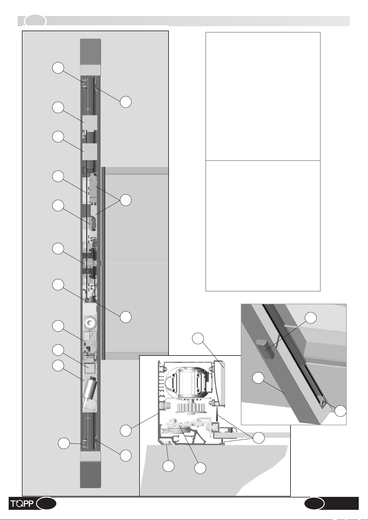
2.4
DESCRIPTION OF COMPONENTS
11
10
5 678
15
13
Power supply and lighting control board
Connector, lighting power supply
Brushes
Door panel stops
11 -
12 -
13 -
Gearmotor unit
Main crossbar
1 -
Electronic board assembly
2 -
3 -
Connector, general power supply
14 -
15 -
Carriage with double wheel
Door panel drive bracket
4 -
5 -
Connectors, side lamp
16 -
Belt pulley and encoder
6 -
Ceiling lamp18 -
17 - Cover casing
Toothed transmission belt
Door lock with manual release
7 -
8 -
Internal sensor
Wall brackets
19 - Side spotlight
20 -
21 -
Emergency battery
Photocell control unit
9 -
10 -
14 16
20
18
9
2 3
17
19
1
11
12
16
21
4
EN
INSTRUCTIONS FOR INSTALLATION AND USE
7
DUEVILLE
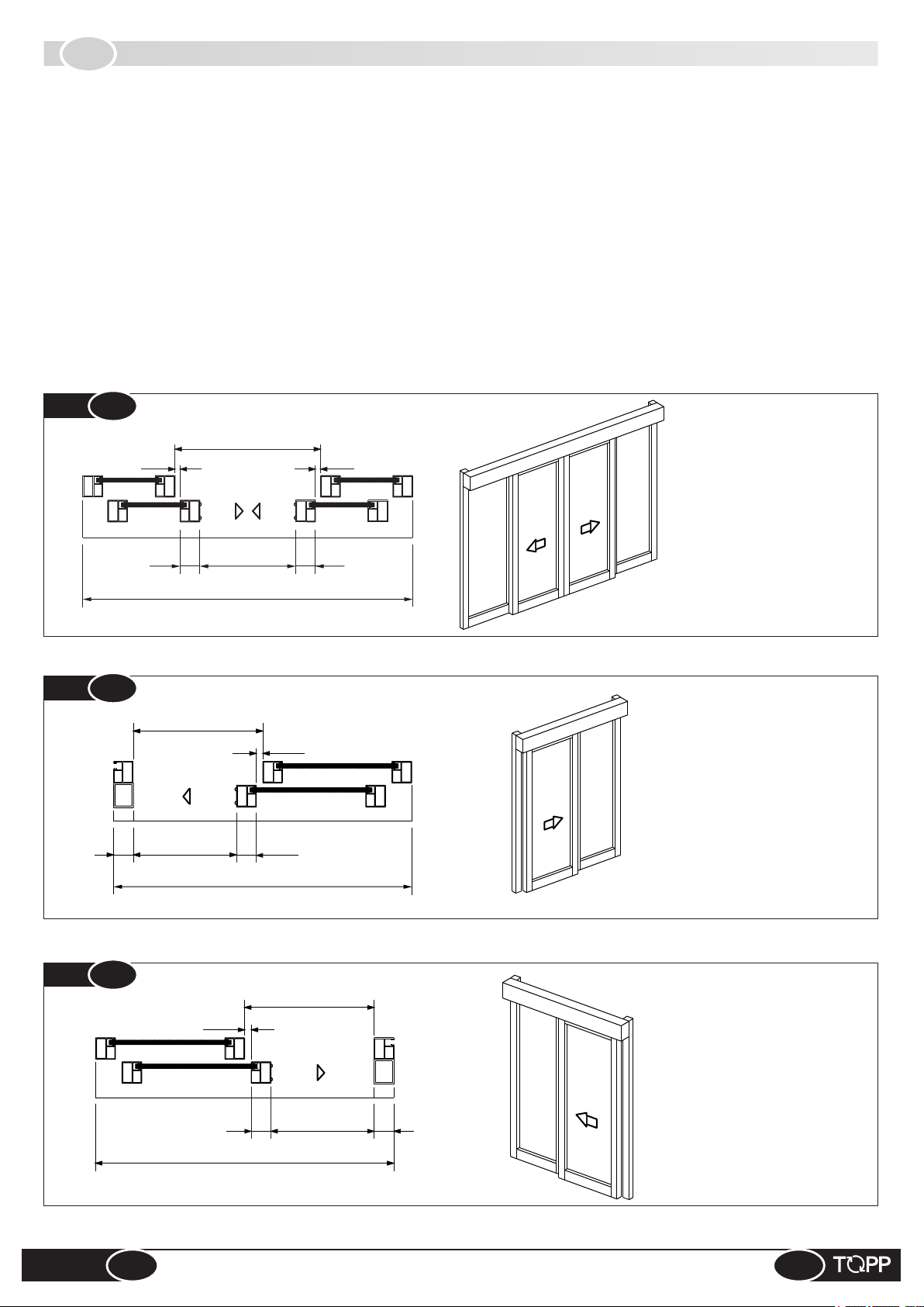
2.5
Two models of automation are available:
- automation with 2 door panels (Fig.2) which allows a pair of door panels to glide simultaneously in opposite directions;
- automation with 1 door panels which allows a single door panel to glide in one direction; Fig.3 shows an application with a
single door that opens toward the right (seen from the front of the automation); Fig.4, shows a single door that opens
toward the left (seen from the front of the automation).
@ When order a single door panel application, always specify the direction of opening of the door, seen from the front of the
automation.
@ To comply with the safety regulations, the glide of the door panel VPA must be less than the door opening width VL.
The glide of the door panel VPA is equal to VL when the upright on the door does not have any roundings and/or protrusions
that could cause a shearing effect.
MODELS
Fig.
Fig.
75
2
2 DOOR PANELS
VL
25 25
75
VPA*
LT/LC
3
1 RIGHT DOOR PANEL
VL
VPA*
75
25
75
PC
C
T/L
L
C
P
P
B
C
/L
T
LT
/
LC
L
PC
BP
C
P
VPA = net doorway width
VL = gross opening
LT/LC = lautomation length/
casing length
BP = rail + runner on the
floor
PC = electric wire raceway
VPA = net doorway width
VL = gross opening
LT/LC = lautomation length/
casing length
BP = rail + runner on the
floor
PC = electric wire raceway
Fig.
DUEVILLE
4
1 LEFT DOOR PANEL
25
75
LT/LC
8
LT/LC
VPA*
75
P
C
BP
BP
L
T
/LC
PC
INSTRUCTIONS FOR INSTALLATION AND USE
VPA = net doorway width
VL = gross opening
LT/LC = lautomation length/
casing length
BP = rail + runner on the
floor
PC = electric wire raceway
EN
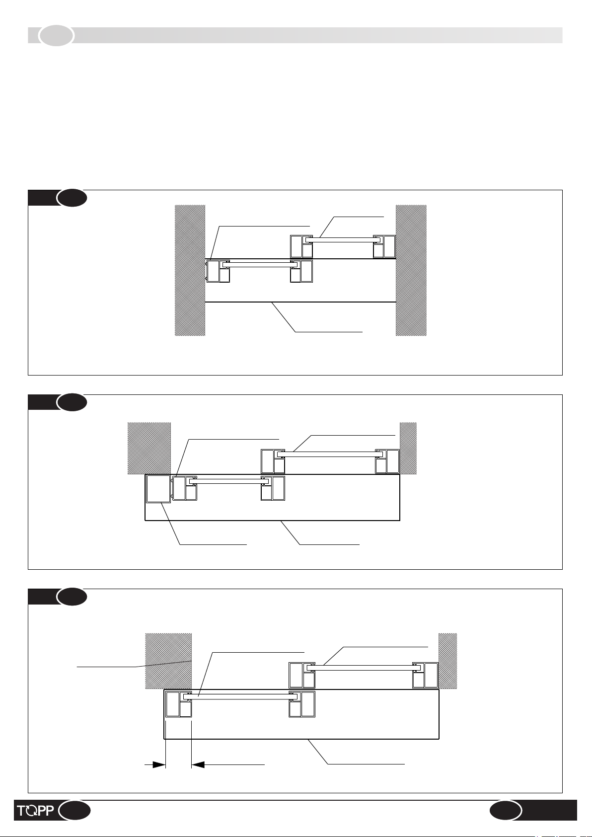
2.6
To reduce the hazard of getting the fingers caught, we recommend the assembly type as shown in Fig.5a and Fig.5b, where
the wall and/or tubular frame act as a jamb and stop the door panel.
Alternatively, proceed as shown in Fig.6 overlapping the end of the wall (and/or closing upright) with the profile of the sliding
panel and moderating the closing speed and speed of approach of the door.
@ In some countries the laws forbid this type of assembly as there is a possible risk of getting the fingers caught.
SLIDING DOORS WITH ONE PANEL
Fig.
Fig.
5a
5b
Sliding door panel
Sliding door panel
Fixed door
panel
Automation
Fixed door panel
Fig.
6
EN
Wall end
Tubular jamb
Sliding door panel
Overlap
Automation
Fixed door panel
Automation
INSTRUCTIONS FOR INSTALLATION AND USE
9
DUEVILLE

IT
3
INSTALLATION
3.1
3.2 - GENERAL WARNING
3.3 - PACKING
3.4 - PRE-INSTALLATION PREPARATION
3.5 - FITTING WALL BRACKETS
3.6 - FITTING AUTOMATION MOUNTING BOLTS
3.7 - RUNNING THE CABLES
3.8 - FITTING GLIDE RUNNERS
3.9 - FITTING DOOR PANEL DRIVE BRACKETS
3.10 - FITTING ELECTRONIC BOARD AND CEILING LIGHT ASSEMBLY
3.11 - FITTING COVERS AND INTERNAL SENSOR
3.2
INSTALLATION MANUAL CONTENTS
GENERAL RECOMMENDATIONS
The automation must be installed exclusively by competent, qualified technical personnel in possession of the technical
requisites foreseen by the legislation in force in the country of installation.
&
Do not install the automation on the external wall of the building, subject to atmospheric agents (rain, snow, etc.).
&
Do not use the automation in environments with a potentially explosive atmosphere.
&
The glass for door panels shall comply with the provisions of the Standard (EN 16005 4.4.2 - Materials: tempered glass in
accordance with EN 12150_1; stratified glass in accordance with EN ISO 12543-1 and EN ISO 12543-2).
&
During installation of the door, take care to avoid any risks during the movement of closure and/or opening the door, and to
protect against risks in accordance with the provisions of standard EN 16005 at item 4.6.21 for the door opening movement
and item 4.6.2.2 for door closure. Protection of the primary closing edge should take account of the types of users of the door
(see EN 16005, 4.6.2.2).
&
The forces developed by the complete system during operation must respect the regulations in force in the country of
installation; if this is not possible, protect and signal by means of electronic safety devices the zones affected by those forces.
&
Before installing the automation, verify that the structure to be automated is stable, sturdy and able to withstand the weight
of the automation and, if necessary, take steps to ensure that it is. Topp spa is not liable for failure to comply with the rules of
good workmanship in the construction of the door panels to motorize, or for any distortions that may develop with use of the
device.
3.3
PACKING
Every standard product package (cardboard carton) contains:
% N.1 DUEVILLE automatic door (complete with motor unit and belt transmission preassembled on the crossbar, side caps,
casing, cable raceway);
% N.2 Carriage units with relative hardware for fastening to the adapter;
% N.2 Supporting brackets on the crossbar;
% N. 2 Warning labels for moving wings that have to be sticked on the centre of the moving wings (refer to picture A);
% N.1 Internal sensor;
% N.2 Brackets belt-cart with relative hardware;
% N.2 brackets belt with relative hardware;
Make sure the parts described above are in the package and that the automation has not undergone any damage in shipment.
If you find anything unusual, do not install the automation and request the service department of the local retailer or the
manufacturer.
@ The number of some of the parts described above
Ref.
may vary depending on the type of configuration
(e.g. number of door panels). If more parts are
necessary, contact the manufacturer.
Warning labels
for moving wings
DUEVILLE
10
INSTRUCTIONS FOR INSTALLATION AND USE
EN

1
3.4
PRE-INSTALLATION PREPARATION
3
1
3
2
2
2
bolt
connector
bolt
bolt
bolt
bolt
bolt
bolt
bolt
bolt
bolt
3
connector
1. Remove the central cover (2 no. bolts).
2. Remove the casing covers (follow the numerical order).
3. Remove the ceiling lamp (unscrew 10 no. screws and disconnect 3 no. connectors).
EN
INSTRUCTIONS FOR INSTALLATION AND USE
connector
11
DUEVILLE

Do not remove
4
Ch.6
5
STANDARD COMPONENTS
RUNN ER
WALL
BRAC KETS
GLID E
RUNN ER
BELT
BRAC KET
M6 x 12
BRAC KET
BELT
SENS OR
12 X 6 X 1.6
Do not damage the glide
runner guide
M8 x 16
16 X 8 X 1.6
M8
M6 x 8
M4 x 10
4. Remove electronic board assembly (unscrew 2 no. bolts).
5. Remove the automation from the packaging.
DUEVILLE
12
INSTRUCTIONS FOR INSTALLATION AND USE
EN
6
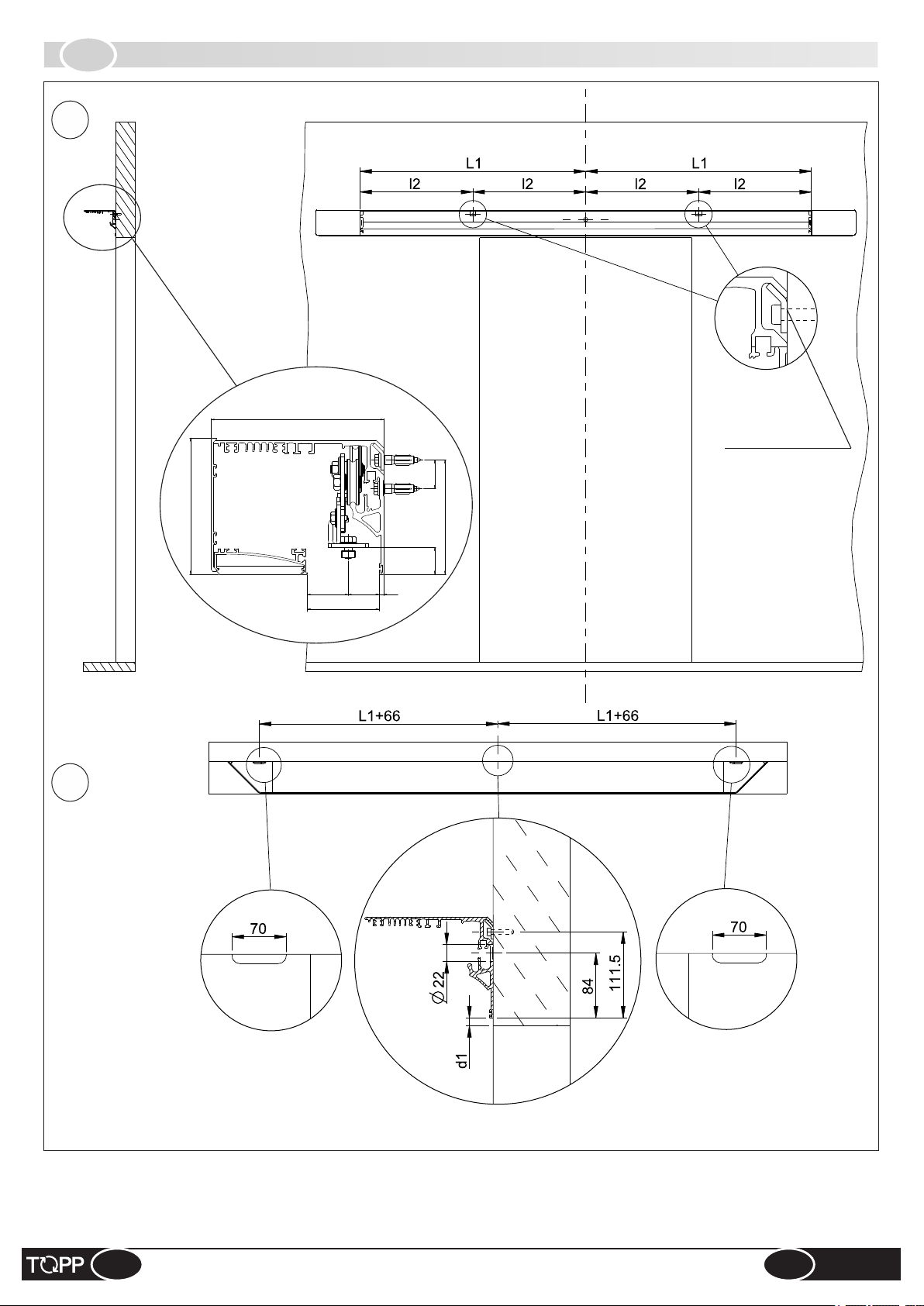
3.5
FITTING WALL BRACKETS
168.5
Wall bracket
28~
133
112
CENTRE LINE OF DOORWAY
26±10
40±9
30±9
70
4.5
7
6. Fit 2 no. wall brackets (use 2 no. suitable Ø6 mm screws, not supplied).
7. Provide cable outlet on wall (3 no. possible cable entry points on automation).
EN
INSTRUCTIONS FOR INSTALLATION AND USE
13
DUEVILLE
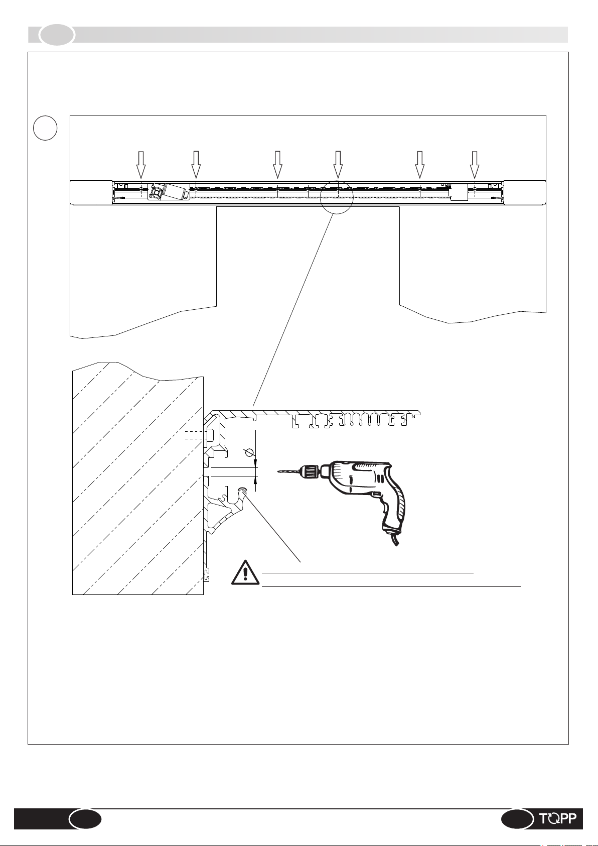
8
3.6
FITTING AUTOMATION MOUNTING BOLTS
hole
hole
6.5
hole
hole
hole
hole
Do not damage the surface of the crossbar.
Carefully clean drilling residues from the sliding area.
8. Drill the wall in line with the holes on the automation and fix it with suitable Ø6 mm screws (not supplied),
using all the available holes.
DUEVILLE
14
INSTRUCTIONS FOR INSTALLATION AND USE
EN
9
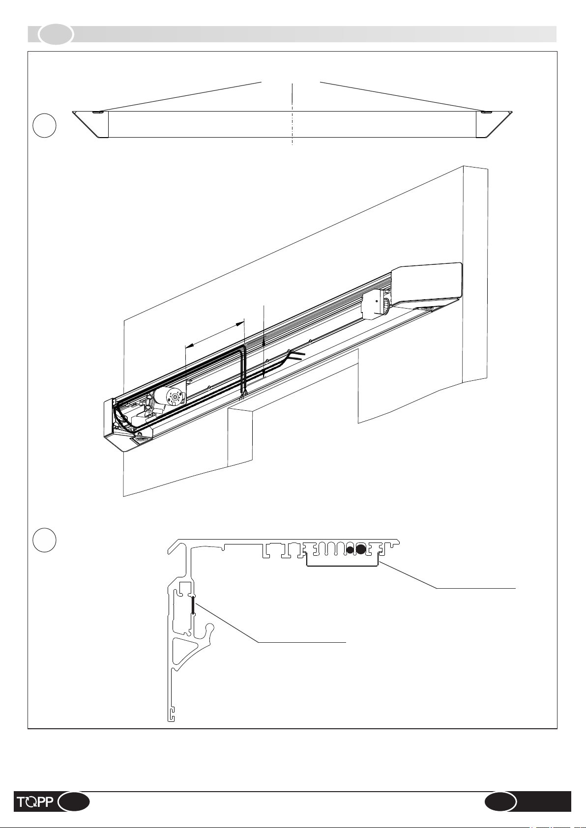
3.7
RUNNING THE CABLES
CABLE ENTRY
150
530
10
Raceway cover seal
9. Cable raceway (supply cable and sensor cable): maintain the indicated lengths.
10. Fit the raceway cover seal and the cable clamp plate (2 no. screws).
EN
INSTRUCTIONS FOR INSTALLATION AND USE
Cable clamp plate
15
DUEVILLE
11
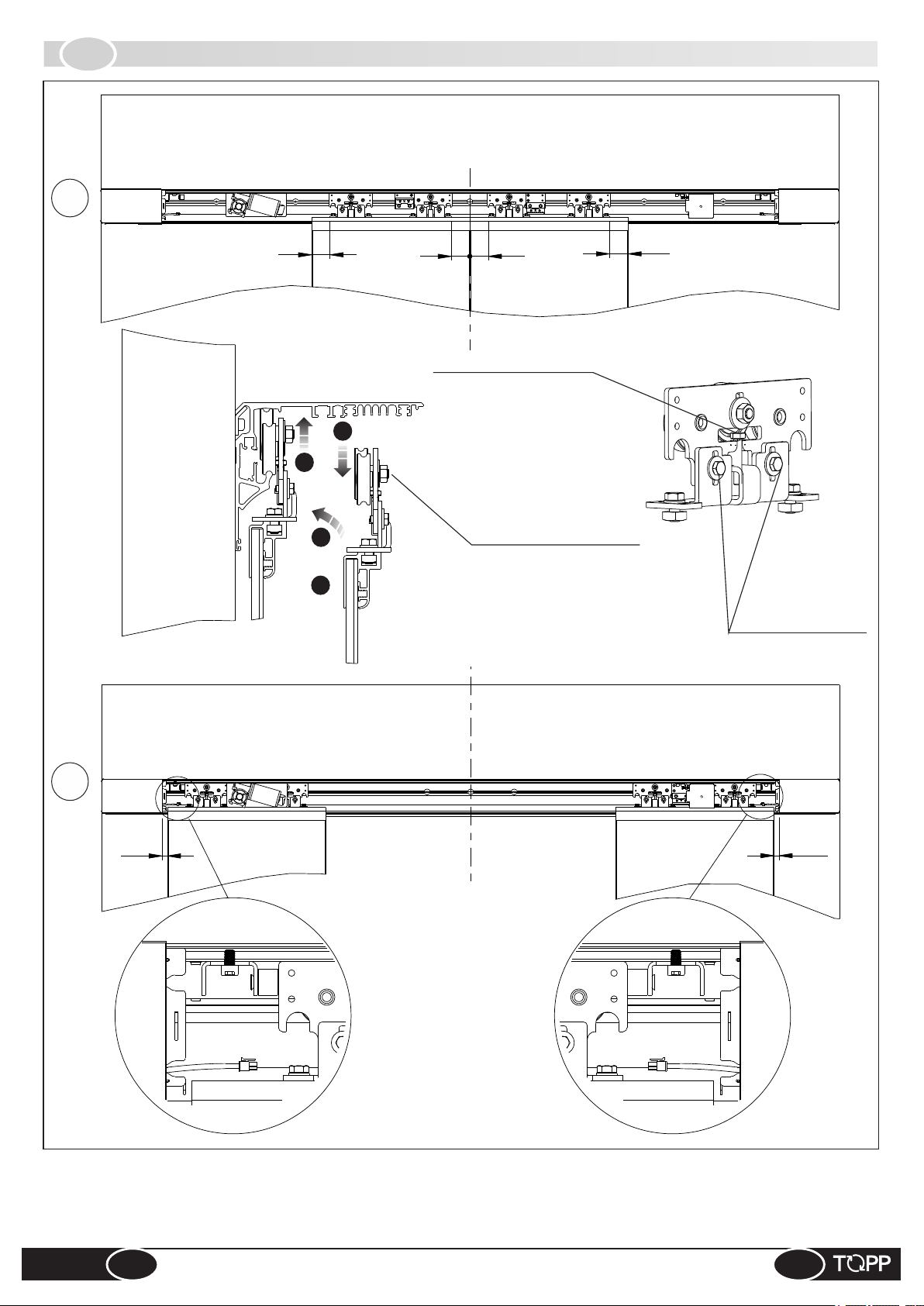
3.8
FITTING GLIDE RUNNERS
70
70
Height adjusting bolt
2
4
3
1
70
Height adjusting bolt,
anti-derailment wheel
70
Runner height
fixing bolts
12
20
11. Fit the runners onto the door panel, lower the anti-derailment wheel, hook the glide runners onto the
crossbar, return the anti-derailment wheel to the higher position. Adjust the height of the glide runner.
12. Adjust both the door panel stops.
20
DUEVILLE
16
INSTRUCTIONS FOR INSTALLATION AND USE
EN
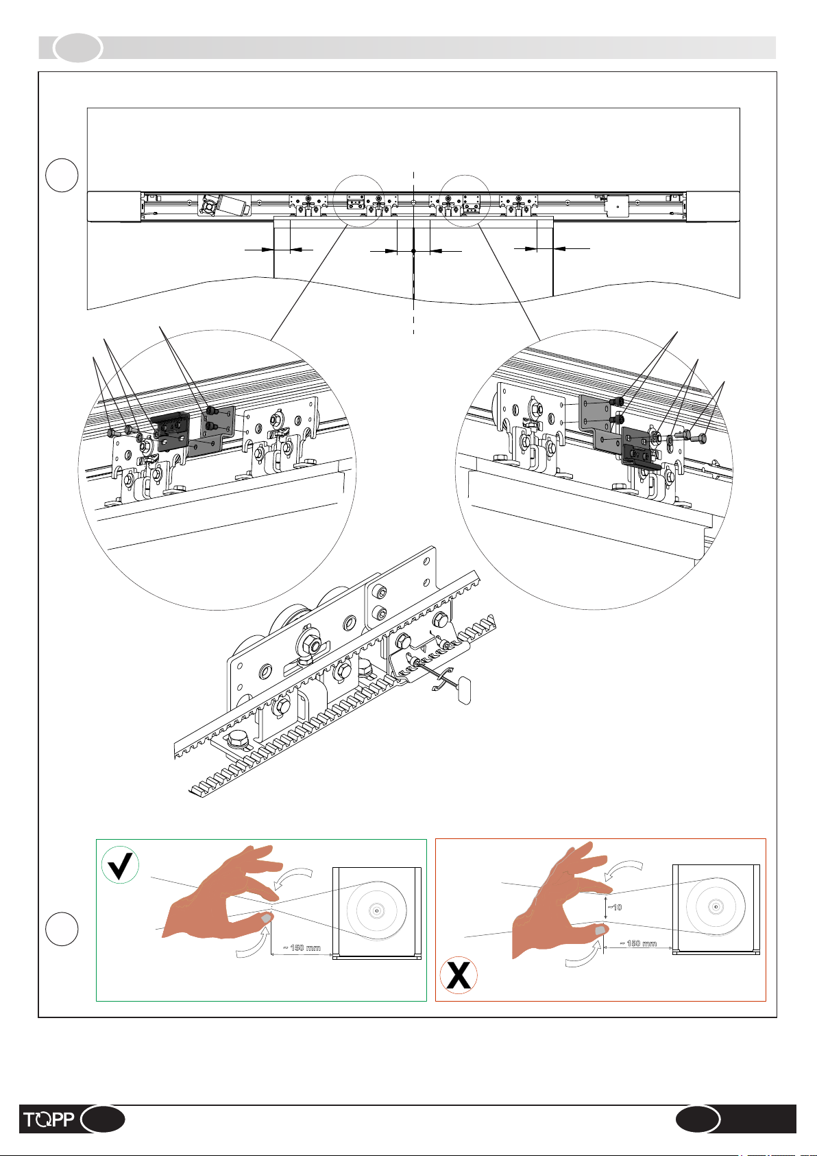
13
3.9
FITTING DOOR PANEL DRIVE BRACKETS
Washer Ø12
Bolt M6x12
Bolt M6x8
70
70
70
70
Bolt M6x8
Washer Ø12
Bolt M6x12
14
It should be easy to pinch together
with thumb and finger.
13. Fit the door panel drive brackets and the transmission belt;
14. Check the belt tension.
Ch3
If it is difficult, adjust.
EN
INSTRUCTIONS FOR INSTALLATION AND USE
17
DUEVILLE
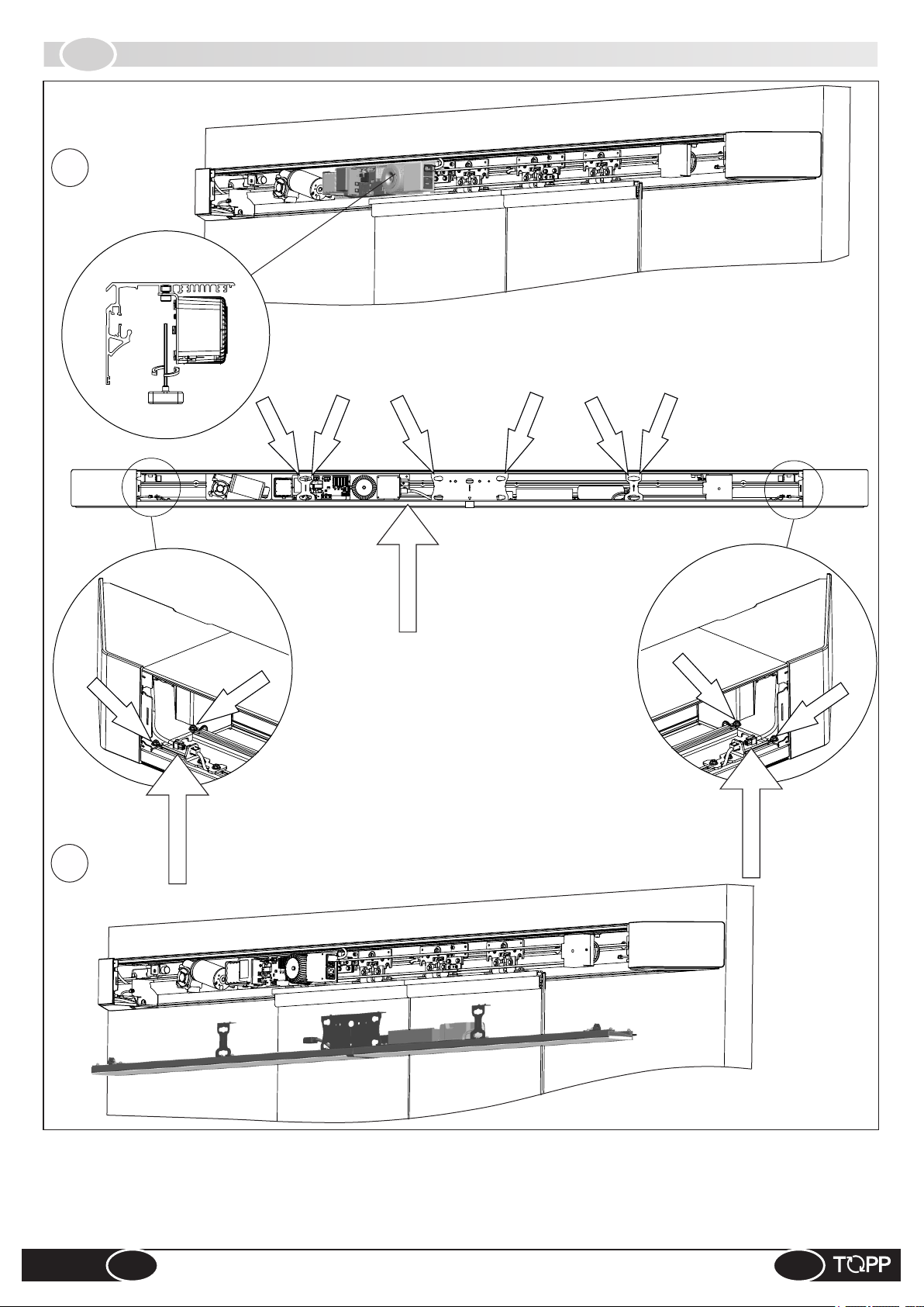
3.10
15
FITTING ELECTRONIC BOARD AND CEILING LIGHT ASSEMBLY
bolt
Ch.6
bolt
bolt
bolt
bolt
connector
bolt
bolt
bolt
bolt
bolt
17
connector
connector
15. Fit the electronic board assembly (2 no. screws).
16. ATTENTION: before moving on to the next step, carry out the electrical wiring (chapter 4)
and the operational test of the entire automation, mounting the internal sensor
provisionally.
17. Fit the ceiling lamp (10 no. screws and connect 3 no. connectors).
DUEVILLE
18
INSTRUCTIONS FOR INSTALLATION AND USE
EN

3.11
FITTING COVERS AND INTERNAL SENSOR
18
19
1
1
2
2
Bolt M4x10
20
18. Refit the casing covers (follow the numerical order).
19. Fit the internal sensor to the central cover (2 no. screws).
20. Connect the internal sensor and fix the central cover (2 no. screws).
EN
INSTRUCTIONS FOR INSTALLATION AND USE
19
DUEVILLE

IT
4
ELECTRICAL CONNECTION
4.1
& Whatever type of electrical material is used for connection (plug, cord, terminals, etc.), it must be suitable for the use, with
the “CE” seal of approval and must comply with the requisites foreseen by the laws in force in the country of installation. For
the wiring, use cables with double insulation up to the immediate vicinity of the connectors.
& The electrical power line to which the control unit is connected must comply with the requisites foreseen by the laws in force
in the country of installation, and must comply with the technical requisites listed in table 1 and on the “CE” rating plate .
& The power supply system to which the equipment is connected shall be provided with an omnipolar magneto-thermal
differential 30mA switch with aperture of at least 3 mm between the contacts. This device shall be installed in the power supply
system in accordance with the requisites contemplated in the legislation in force in the country of installation.
& The installation must include a ground wire longer than the power cord so that, in case of traction, the ground wire is the last
to stretch.
& We recommend the following types of power cables: H05VV-F 3X0.75, H05RN-F 3X0.75.For the analogue switch cable
we recommend using a multipole 8 x 0.5 cable type LI-YY, and for the digital switch 4x0.5 LI-YY. (Cable ‘shielding’ should only
be used for cable lengths in excess of 20 meters).
& Before making electrical connection of the automation, make sure the power cord has not been damaged.
& The hole drilled on the profile for passage of the power cord must be made without any rough or sharp edges or sharp
corners that could damage the wire.
GENERAL RECOMMENDATIONS
Electrical connection of the automation must be made exclusively by qualified technical personnel in possession o fthe
professional requisites foreseen by the laws in the country of installation, who must issue the client a certificat eof
conformity of the connection and/or installation made.
Fig.
4.2
ELECTRONIC CIRCUIT BOARD
8
9
6
10
1. Infrared sensor input,
microwave sensors,
photocells, door opening
safety guard
2. Input for program selector
8
3
5
2
1
PC
4
12
Ds2
Ds3
Ds4
14
1
1
don’t touch
13
input with knob
3. Input for lateral guards,
antipanic device and test
sensors
4. Digital switch input
5. Input for air curtain, lamp,
key switch, emergency key,
smoke detectors
6. Emergency battery system
input
7. Gearmotor input
8. Door block 1 input
9. Door block 2 input
(pharmacy)
10. Transformer input
11. Lighted display
12. Encoder cord input
13. DOWN key
14. ENTER key
DUEVILLE
20
7
INSTRUCTIONS FOR INSTALLATION AND USE
EN

4.3
PRE-WIRED ELECTRIC CONNECTIONS
Fig.
9
M
OT
O
R
Red
Black
BATTE
R
Y
Black
Red
N
CI
RC
U
IT
B
EN
ELT TR
COD
ER
A
NSM
I
S
S
I
O
TRA
NS
F
O
RME
R
1 9 17 25
2 10 18 26
3 11 19 27
4 12 20 28
5 13 21 29
6 14 22 30
7 15 23 31
8 16 24 32
1. SMOKE FIRE
SYSTEM
2. EMERGENCY
3. CLOSURE
KEY
4. OPENING KEY
5. LAMP
6. AIR CURTAINS
7. GND
8. 24V*
Ÿ 24v
Ÿ GND
Ÿ SIGNAL A
Ÿ GND (shield)
Ÿ SIGNAL B
F
POWER SUPPLY
9. TEST+
10. TEST+
11. GND
12. ANTIPANIC
DEVICE
13. LATERAL
SAFETY 2
14. LATERAL
SAFETY 1
15. GND
16. 24V
17. INTERNAL
SECURITY
18. INTERNAL
RADAR
19. GND
20. GND
21. EXTERNAL
SECURITY
22. EXTERNAL
RADAR
23. GND
24. 24V
25. RESET
(NEAR)
26. OPEN
27. PARTIAL
28. EXIT ONLY
29. ENTER
ONLY
30. CLOSED
31. GND
32. 24V
EN
* Unregolated
INSTRUCTIONS FOR INSTALLATION AND USE
21
DUEVILLE

4.4
ELECTRICAL WIRING DIAGRAM (FLOW CHART)
Fig.
10
L
+ 2 Lateral sensor
2 Activation sensors
+ Photocells
I
1 Activation/Safety
+
sensor
+ Photocells
1 Lateral sensor
+1 Activation Sensor
O
2 Sensors on
Hotron
+
passenger cab
2 Lateral sensor
Optex
Oo Oh
Hotron
N
SENSORS MONITORED
ACTIVATION WITH SAFETY
M
+
2 Sensors on
passenger cab
1 Lateral sensor
No Nh
Optex
Hotron
sensors
2 Activation/Safety
+ 2 Lateral sensors
CON LATERALI
G
+
+ Photocells
1 Lateral sensor
2 Activation sensors
2 Sensors on
passenger cab
Mo Mh
Optex
START
ACTIVATION WITH
SAFETY SENSORS
F H
2 Activation/Safety
sensors
+1 Lateral sensor
E
sensor
+ Photocells
1 Activation/Safety
+ 2 Lateral sensors
+1 Activation Sensor
D
Sensor
+ Photocells
1 Activation/Safety
+1 Activation Sensor
DUEVILLE
22
A
activation
2 Sensors
ONLY ACTIVATION
INSTRUCTIONS FOR INSTALLATION AND USE
LATERAL
WITHOUT IS5
C
2 Activation/Safety
Sensors +Photocells
B
2 Activation/Safety
Sensors
EN

4.5
CONNECTION OF DETECTION SENSORS
Fig.
A
¬ Digital program switch menu: PARAMETERS> OTHER PARAMETERS>
SAFETY SENSOR LOGIC: N.C. WITHOUT TEST
Or program parameter 9 with the dot
17
18
19
12 20
13 21
14 22
15 23
24
24 23
18
20
20
22
23
24
whitewhitewhite
yellowyellowyellow
greygreygrey
greygreygrey
whitewhitewhite
yellowyellowyellow
ACTI VATION
COM
N.O.
SENSOR
GND
+24V
IS1 EXTERNAL ACTIVATION
ACTI VATION
COM
N.O.
Fig.
B
¬ Digital program switch menu: PARAMETERS> OTHER PARAMETERS>
SAFETY SENSOR LOGIC: N.C. WITHOUT TEST
Or program parameter 9 with the dot
17
18
19
12 20
13 21
14 22
15 23
24
21
green/blackgreen/blackgreen/black
white/blackwhite/blackwhite/black
19
22
20
23
24
greygreygrey
greygreygrey
yellowyellowyellow
whitewhitewhite
greygreygrey
greygreygrey
GND
+24V
N.C.SEC
COM.SEC
NO ACT.
COM. ACT.
GND
+24V
SENSOR
IS1 INTERNAL ACTIVATION
SENSOR
IS2 IS2 EXTERNAL ACT./SAFETY
EN
17
green/blackgreen/blackgreen/black
19
18
20
23
24
INSTRUCTIONS FOR INSTALLATION AND USE
white/blackwhite/blackwhite/black
yellowyellowyellow
whitewhitewhite
greygreygrey
greygreygrey
N.C. SAF
COM. SAF
NO ACT.
COM. ACT.
GND
+24V
DUEVILLE
23
SENSOR
IS2 IS2 INTERNAL ACT./SAFETY

Fig.
C
¬ Digital program switch menu:
PARAMETERS>OTHER PARAMETERS>
SAFETY SENSOR LOGIC: N.C. WITH TEST
Or program parameter 9 without the dot
GNDGNDGND
24
15
19
23
F1 - F2
CIRCUIT
PHOTOCELLS
24V24V24V
RX1RX1RX1
COM RXCOM RXCOM RX
RX2RX2RX2
TEST -TEST -TEST -
TEST +TEST +TEST +
TX1TX1TX1
COM TXCOM TXCOM TX
OUTOUTOUT
RX1RX1RX1
COM RXCOM RXCOM RX
GNDGNDGND
9
21
RX2RX2RX2
TX1TX1TX1
TEST +TEST +TEST +
TEST -TEST -TEST -
COM TXCOM TXCOM TX
redredred
Tx2Tx2Tx2
OUTOUTOUT
21
redredred
OUTOUTOUT
OUTOUTOUT
19
24V24V24V
TEST+TEST+TEST+
TEST-TEST-TEST-
9
18
19
20
21
22
15 23
24
OUTOUTOUT
OUTOUTOUT
23
22
20
18
TX1TX1TX1 TX2TX2TX2
whitewhitewhite
whitewhitewhite
RX1RX1RX1 RX2RX2RX2
RX1 - TX1 = First beam
RX2 - TX2 = Second beam
ACTIVATION
22
20
23
24
yellowyellowyellow
whitewhitewhite
greygreygrey
greygreygrey
N.O.
COM
GND
+24V
SENSOR
DUEVILLE
24
greygreygrey
18
20
23
24
INSTRUCTIONS FOR INSTALLATION AND USE
yellowyellowyellow
whitewhitewhite
greygreygrey
greygreygrey
IS1 EXTERNAL ACTIVATION
ACTIVATION
N.O.
COM
SENSOR
GND
+24V
IS1 INTERNAL ACTIVATION
EN

Fig.
D
¬ Digital program switch menu:
PARAMETERS>OTHER PARAMETERS>
SAFETY SENSOR LOGIC: N.C. WITHOUT TEST
Or program parameter 9 with the dot
F1-F2
CIRCUIT
PHOTOCELLS
24V24V24V
RX1RX1RX1
COM RXCOM RXCOM RX
RX2RX2RX2
TEST -TEST -TEST -
TEST +TEST +TEST +
TX1TX1TX1
COM TXCOM TXCOM TX
OUTOUTOUT
RX1RX1RX1
COM RXCOM RXCOM RX
GNDGNDGND
RX2RX2RX2
TX1TX1TX1
TEST +TEST +TEST +
TEST -TEST -TEST -
COM TXCOM TXCOM TX
redredred
Tx2Tx2Tx2
redredred
21
OUTOUTOUT
OUTOUTOUT
OUTOUTOUT
19
OUTOUTOUT
OUTOUTOUT
24V24V24V
17
18
19
12 20
13 21
14 22
15 23
24
24
GNDGNDGND
whitewhitewhite
whitewhitewhite
RX1RX1RX1 RX2RX2RX2
TX1TX1TX1 TX2TX2TX2
22
20
23
24
RX1 - TX1 = First beam
RX2 - TX2 = Second beam
yellowyellowyellow
whitewhitewhite
greygreygrey
greygreygrey
N.O.
COM
GND
+24V
ACT.
SENSOR
IS1 EXTERNAL ACTIVATION
EN
17
green/blackgreen/blackgreen/black
19
white/blackwhite/blackwhite/black
18
20
23
24
INSTRUCTIONS FOR INSTALLATION AND USE
yellowyellowyellow
whitewhitewhite
greygreygrey
greygreygrey
N.C.
COM
N.O.
COM
GND
+24V
25
SEC.
ACT.
SENSOR
IS2 INTERNAL ACTIVATION/SAFETY
DUEVILLE

Fig.
E
¬ Digital program switch menu:
PARAMETERS>OTHER PARAMETERS> SAFETY SENSOR LOGIC: N.C. WITHOUT
TEST
Or program parameter 9 with the dot
23
F1 - F2
CIRCUIT
14
N.C.
COM
PHOTOCELLS
24V24V24V
RX1RX1RX1
GNDGNDGND
COM RXCOM RXCOM RX
24
RX2RX2RX2
GNDGNDGND
TEST -TEST -TEST -
TX1TX1TX1
TX1TX1TX1
TEST +TEST +TEST +
TEST -TEST -TEST -
COM TXCOM TXCOM TX
Tx2Tx2Tx2
21
OUTOUTOUT
OUTOUTOUT
redredred
redredred
TX1TX1TX1 TX2TX2TX2
whitewhitewhite
whitewhitewhite
RX1RX1RX1 RX2RX2RX2
RX1 - TX1 = First beam
19
OUTOUTOUT
OUTOUTOUT
RX2 - TX2 = Second beam
16
15
16
13
15
15
16
GND
+24V
N.C.
COM
GND
+24V
IS5 LATERAL SENSOR 1
Is5 LATERAL SENSOR 2
24V24V24V
17
18
11 19
12 20
13 21
14 22
15 23
16 24
15
14
13
22
20
23
24
17
green/blackgreen/blackgreen/black
white/blackwhite/blackwhite/black
19
18
20
yellowyellowyellow
whitewhitewhite
greygreygrey
greygreygrey
yellowyellowyellow
whitewhitewhite
N.O.
COM
GND
+24V
N.C.
COM
N.O.
COM
ACT.
IS1 SENSORE ATTIV. ESTERNO
SEC.
ACT.
DUEVILLE
26
23
24
INSTRUCTIONS FOR INSTALLATION AND USE
greygreygrey
greygreygrey
GND
+24V
IS2 SENSORE ATTIV./SIC. INTERNO
EN

Fig.
F
¬ Digital program switch menu:
PARAMETERS>OTHER PARAMETERS>
SAFETY SENSOR LOGIC: N.C. WITHOUT TEST
Or program parameter 9 with the dot
IS2 EXTERNAL ACTIVATION/SAFETY
SENSOR
N.C.SEC
green/blackgreen/blackgreen/black
21
NO ACT.
COM.ACT.
COM.SEC
GND
greygreygrey
whitewhitewhite
yellowyellowyellow
white/blackwhite/blackwhite/black
19
22
20
23
+24V
greygreygrey
24
IS2 INTERNAL ACTIVATION/SAFETY
SENSOR
N.C.SEC
green/blackgreen/blackgreen/black
17
NO ACT.
COM.SEC
GND
COM.ACT.
whitewhitewhite
yellowyellowyellow
greygreygrey
white/blackwhite/blackwhite/black
19
18
20
23
+24V
greygreygrey
24
18
12 20
13 21
15 23
17
11 19
16 24
14 22
N.C.N.C.N.C.
24V24V24V
IS5 LATERAL S.
N.C.
14
COM
GND
15
24V
16
EN
GNDGNDGND
INSTRUCTIONS FOR INSTALLATION AND USE
27
DUEVILLE

Fig.
G
¬ Digital program switch menu:
PARAMETERS>OTHER PARAMETERS>
SAFETY SENSOR LOGIC: N.C. WITHOUT TEST
Or program parameter 9 with the dot
24
21
F1 - F2
CIRCUIT
PHOTOCELLS
24V24V24V
RX1RX1RX1
COM RXCOM RXCOM RX
RX2RX2RX2
TEST -TEST -TEST -
TEST +TEST +TEST +
TX1TX1TX1
COM TXCOM TXCOM TX
OUTOUTOUT
RX1RX1RX1
COM RXCOM RXCOM RX
GNDGNDGND
RX2RX2RX2
TX1TX1TX1
TEST +TEST +TEST +
TEST -TEST -TEST -
COM TXCOM TXCOM TX
Tx2Tx2Tx2
OUTOUTOUT
OUTOUTOUT
OUTOUTOUT
GNDGNDGND
24V24V24V
17
18
11 19
12 20
13 21
14 22
15 23
16 24
N.C.N.C.N.C.
19
23
18
20
22
2424
23
whitewhitewhite
RX1RX1RX1 RX2RX2RX2
TX1TX1TX1 TX2TX2TX2
whitewhitewhite
22
20
23
redredred
redredred
RX1 - TX1 = First beam
RX2 - TX2 = Second beam
ACTIVATION
yellowyellowyellow
whitewhitewhite
greygreygrey
N.O.
COM
GND
SENSOR
DUEVILLE
14
15
16
28
24
N.C.
COM
18
GND
24V
IS5 LATERAL S.
20
23
24
INSTRUCTIONS FOR INSTALLATION AND USE
greygreygrey
yellowyellowyellow
whitewhitewhite
greygreygrey
greygreygrey
+24V
ACTIVATION
N.O.
COM
GND
+24V
EN
IS1 EXTERNAL ACTIVATION
SENSOR
IS1 SINTERNAL ACTIVATION

Fig.
H
¬ Digital program switch menu:
PARAMETERS>OTHE R PA RAMETER S> S AF ETY SENSOR
LOGIC: N.C. WITHOUT TEST
¬ Or program parameter 9 with the dot
17
18
11 19
12 20
13 21
14 22
15 23
16 24
21
green/blackgreen/blackgreen/black
white/blackwhite/blackwhite/black
19
22
20
23
24
green/blackgreen/blackgreen/black
17
19
white/blackwhite/blackwhite/black
18
20
23
24
yellowyellowyellow
whitewhitewhite
greygreygrey
greygreygrey
yellowyellowyellow
whitewhitewhite
greygreygrey
greygreygrey
N.C.SEC
COM.SEC
NO ACT.
COM. ACT.
GND
+24V
IS2 EXTERNAL ACTIVATION/SAFETY S.
N.C.SEC
COM.SEC
NO ACT.
COM. ACT.
GND
+24V
IS2 INTERNAL ACTIVATION/SAFETY S.
14
15
16
13
15
16
N.C.
COM
GND
24V
N.C.
COM
GND
24V
IS5 LATERAL S. 1
IS5 LATERAL S. 2
EN
INSTRUCTIONS FOR INSTALLATION AND USE
29
DUEVILLE

Fig.
I
¬ Digital program switch menu:
PARAMETERS>OTHER PARAMETERS>SAFETY SENSOR LOGIC: N.C. WITHOUT TEST
Or program parameter 9 with the dot
PHOTOCELLS
F1 - F2
CIRCUIT
24V24V24V
GNDGNDGND
RX1RX1RX1
TEST +TEST +TEST +
TEST -TEST -TEST -
COM RXCOM RXCOM RX
RX2RX2RX2
TX1TX1TX1
OUTOUTOUT
OUTOUTOUT
Tx2Tx2Tx2
OUTOUTOUT
OUTOUTOUT
COM TXCOM TXCOM TX
N.C.
redredred
redredred
TX1TX1TX1 TX2TX2TX2
COM
GND
24V24V24V
GNDGNDGND
24V
whitewhitewhite
whitewhitewhite
RX1RX1RX1 RX2RX2RX2
RX1 - TX1 = First beam
RX2 - TX2 = Second beam
14 15 16
2324
21
19
IS5 LATERAL S.
N.C.N.C.N.C.
24V24V24V
GNDGNDGND
17
18
11 19
12 20
13 21
14 22
15 23
16 24
22
20
23
24
17
green/blackgreen/blackgreen/black
white/blackwhite/blackwhite/black
19
18
20
23
24
yellowyellowyellow
whitewhitewhite
greygreygrey
greygreygrey
yellowyellowyellow
whitewhitewhite
greygreygrey
greygreygrey
N.O.
COM
GND
+24V
N.C.
COM
N.O.
COM
GND
+24V
ACT.
IS1 EXTERNAL ACTIVATION SENSOR
SEC.
ACT.
IS2 INTERNAL ACTIVATION/SAFETY S
DUEVILLE
30
INSTRUCTIONS FOR INSTALLATION AND USE
EN

Fig.
¬ Digital program switch menu:
Or program parameter 9 with the dot
L
PARAMETERS>OTHER PARAMETERS>
SAFETY SENSOR LOGIC: N.C. WITHOUT TEST
24
23
21
F1 - F2
CIRCUIT
PHOTOCELLS
24V24V24V
RX1RX1RX1
COM RXCOM RXCOM RX
RX2RX2RX2
TEST -TEST -TEST -
TEST +TEST +TEST +
TX1TX1TX1
COM TXCOM TXCOM TX
OUTOUTOUT
Tx2Tx2Tx2
OUTOUTOUT
OUTOUTOUT
OUTOUTOUT
TX1TX1TX1
GNDGNDGND
RX1RX1RX1
COM RXCOM RXCOM RX
TEST +TEST +TEST +
TEST -TEST -TEST -
RX2RX2RX2
COM TXCOM TXCOM TX
18
11 19
12 20
13 21
14 22
15 23
16 24
14
N.C.
19
whitewhitewhite
RX1RX1RX1 RX2RX2RX2
182022
redredred
whitewhitewhite
TX1TX1TX1 TX2TX2TX2
RX1 - TX1 = First beam
RX2 - TX2 = Second beam
22
yellowyellowyellow
whitewhitewhite
20
redredred
ACTIVATION
N.O.
COM
EN
15
16
13
16
COM
23
24
GND
24V
N.C.
COM
GND
24V
IS5 S. LATERALE 1
18
20
23
24
IS5 S. LATERALE 2
INSTRUCTIONS FOR INSTALLATION AND USE
greygreygrey
greygreygrey
yellowyellowyellow
whitewhitewhite
greygreygrey
greygreygrey
GND
+24V
ACTIVATION
N.O.
COM
GND
+24V
31
SENSOR
IS1 EXTERNAL ACTIVATION
SENSOR
IS1 INTERNAL ACTIVATION
DUEVILLE

Fig.
Mo
¬ Digital program switch menu:
PARAMETERS>OTHER PARAMETERS> SAFETY SENSOR LOGIC:
N.C. WITH TEST
Or program parameter 9 without the dot
ELECTRICAL WIRING DIAGRAM FOR USING OPTEX
ACTIVATION/SAFETY SENSOR MONITORED
9 17
10 18
19
20
21
22
23
24
19
9
21
19
20
22
23
24
blackblackblack
redredred
pinkpinkpink
blueblueblue
yellowyellowyellow
greengreengreen
whitewhitewhite
brownbrownbrown
TSTTST+
N.C.
+
SECURITY
-
COM
COM
ACTIVATION
N.O.
GND
+24V
TEST
SENSOR MONITORED
IS2 EXTERNAL ACTIVATION/SAFETY
DUEVILLE
32
20
blackblackblack
10
17
20
20
18
23
24
redredred
pinkpinkpink
blueblueblue
yellowyellowyellow
greengreengreen
whitewhitewhite
brownbrownbrown
INSTRUCTIONS FOR INSTALLATION AND USE
TST-
TEST
TST+
N.C.
SECURITY
COM
COM
ACTIVATION
N.O.
GND
+24V
SENSOR MONITORED
IS2 INTERNAL ACTIVATION/SAFETY
EN

Fig.
Mh
¬ Digital program switch menu:
PARAMETERS>OTHER PARAMETERS> SAFETY SENSOR LOGIC:
N.C. WITH TEST
Or program parameter 9 without the dot
ELECTRICAL WIRING DIAGRAM FOR USING HOTRON
ACTIVATION/SAFETY SENSOR MONITORED
9 17
10 18
19
20
21
22
23
24
19
9
21
19
20
22
23
24
brownbrownbrown
greygreygrey
yellowyellowyellow
blueblueblue
greengreengreen
whitewhitewhite
blackblackblack
redredred
TST-
TST+
N.C.
+
SECURITY
-
COM
COM
ACTIVATION
N.O.
GND
+24V
TEST
SENSOR MONITORED
IS2 EXTERNAL ACTIVATION/SAFETY
EN
20
brownbrownbrown
10
17
20
20
18
23
24
greygreygrey
yellowyellowyellow
blueblueblue
greengreengreen
whitewhitewhite
blackblackblack
redredred
INSTRUCTIONS FOR INSTALLATION AND USE
TSTTST+
N.C.
TEST
SECURITY
COM
COM
ACTIVATION
N.O.
GND
+24V
33
SENSOR MONITORED
IS2 INTERNAL ACTIVATION/SAFETY
DUEVILLE

Fig.
No
¬ Digital program switch menu:
PARAMETERS>OTHER PARAMETERS> SAFETY SENSOR LOGIC:
N.C. WITH TEST
Or program parameter 9 without the dot
ELECTRICAL WIRING DIAGRAM FOR USING OPTEX
ACTIVATION/SAFETY SENSOR MONITORED
9 17
10 18
11 19
20
13 21
22
15 23
16 24
19
9
21
19
20
22
23
24
blackblackblack
redredred
pinkpinkpink
blueblueblue
yellowyellowyellow
greengreengreen
whitewhitewhite
brownbrownbrown
TST-
TST+
N.C.
+
SECURITY
-
COM
COM
ACTIVATION
N.O.
GND
+24V
TEST
SENSOR MONITORED
IS2 EXTERNAL ACTIVATION/SAFETY
11
15 16 15 13
greengreengreen
GND
whitewhitewhite
redredred
COM
24V
blueblueblue
N.C.
10
orangeorangeorange
TST -
IS5 LATERALE S.
brownbrownbrown
TST +
20
10
17
20
20
18
23
24
blackblackblack
redredred
pinkpinkpink
blueblueblue
yellowyellowyellow
greengreengreen
whitewhitewhite
brownbrownbrown
TSTTST+
TEST
N.C.
SECURITY
COM
COM
ACTIVATION
N.O.
GND
+24V
SENSOR MONITORED
IS2 INTERNAL ACTIVATION/SAFETY
DUEVILLE
34
INSTRUCTIONS FOR INSTALLATION AND USE
EN

Fig.
Nh
¬ Digital program switch menu:
PARAMETERS>OTHER PARAMETERS> SAFETY SENSOR LOGIC:
N.C. WITH TEST
Or program parameter 9 without the dot
ELECTRICAL WIRING DIAGRAM FOR USING HOTRON
ACTIVATION/SAFETY SENSOR MONITORED
9 17
10 18
11 19
20
13 21
22
15 23
16 24
19
9
21
19
20
22
23
24
brownbrownbrown
greygreygrey
yellowyellowyellow
blueblueblue
greengreengreen
whitewhitewhite
blackblackblack
redredred
TSTTST+
N.C.
+
SECURITY
-
COM
COM
ACTIVATION
N.O.
GND
+24V
TEST
SENSOR MONITORED
IS2 EXTERNAL ACTIVATION/SAFETY
15 16 15 13 11
blackblackblack
GND
redredred
24V
COM
blueblueblue
yellowyellowyellow
N.C.
TST -
Is5 HOTRON
LATERAL S.
10
brownbrownbrown
greygreygrey
TST +
20
10
17
20
20
18
23
24
brownbrownbrown
greygreygrey
yellowyellowyellow
blueblueblue
greengreengreen
whitewhitewhite
blackblackblack
redredred
TSTTST+
N.C.
TEST
SECURUTY
COM
COM
ACTIVATION
N.O.
GND
+24V
SENSOR MONITORED
IS2 NTERNAL ACTIVATION/SAFETY
EN
INSTRUCTIONS FOR INSTALLATION AND USE
35
DUEVILLE

Fig.
Oo
IS2 EXTERNAL ACTIVATION/SAFETY
SENSOR MONITORED
IS2 INTERNAL ACTIVATION/SAFETY
SENSOR MONITORED
¬ Digital program switch menu:
PARAMETERS>OTHER
PARAMETERS> SAFETY
SENSOR LOGIC: N.C. WITH
TEST
Or program parameter 9 without the
dot
ELECTRICAL WIRING
DIAGRAM FOR USING
OPTEX
ACTIVATION/SAFETY
SENSOR MONITORED
TEST
TST-
blackblackblack
19
TST+
redredred
9
SECURITY
N.C.
-
+
pinkpinkpink
21
COM
blueblueblue
19
ACTIVATION
COM
N.O.
greengreengreen
yellowyellowyellow
22
20
GND
+24V
whitewhitewhite
brownbrownbrown
24
23
TEST
TST-
TST+
redredred
blackblackblack
10
20
SECURITY
N.C.
pinkpinkpink
17
20
COM
blueblueblue
ACTIVATION
N.O.
COM
greengreengreen
yellowyellowyellow
18
20
GND
+24V
whitewhitewhite
brownbrownbrown
23
24
10
11
orangeorangeorange
brownbrownbrown
13 21
20
14 22
15 23
10 18
9 17
11 19
14
blueblueblue
15
16
whitewhitewhite
redredred
16 24
15
greengreengreen
10
11
orangeorangeorange
brownbrownbrown
13
blueblueblue
11
16
whitewhitewhite
redredred
15
greengreengreen
DUEVILLE
36
TST +
N.C.
TST -
COM
+24V
GND
TST +
TST -
IS5 LATERAL S. 1 IS5 LATERAL S. 2
INSTRUCTIONS FOR INSTALLATION AND USE
N.C.
COM
+24V
GND
EN

Fig.
Oh
IS2 EXTERNAL ACTIVATION/SAFETY
SENSOR MONITORED
IS2 INTERNAL ACTIVATION/SAFETY
SENSOR MONITORED
¬ Digital program switch menu:
P A R A M E T E R S > O T H E R
P A R A M E T E R S > S A F E T Y
SENSOR LOGIC: N.C. WITH TEST
Or program parameter 9 without the
dot
ELECTRICAL WIRING
DIAGRAM FOR USING
HOTRON
ACTIVATION/SAFETY
SENSOR MONITORED
TEST
TST+
TST-
greygreygrey
brownbrownbrown
9
19
SECURITY
COM
N.C.
-
+
blueblueblue
yellowyellowyellow
21
19
COM
N.O.
ACTIVATION
whitewhitewhite
greengreengreen
22
20
GND
+24V
redredred
blackblackblack
23
24
TEST
TST-
TST+
greygreygrey
brownbrownbrown
10
20
SECURITY
N.C.
COM
blueblueblue
yellowyellowyellow
17
20
N.O.
COM
ACTIVATION
whitewhitewhite
greengreengreen
18
20
GND
+24V
redredred
blackblackblack
24
23
10
greygreygrey
20
10 18
9 17
11
14
brownbrownbrown
yellowyellowyellow
13 21
11 19
14 22
15
16
blueblueblue
redredred
15 23
16 24
15
blackblackblack
10
greygreygrey
11
brownbrownbrown
13
11
yellowyellowyellow
blueblueblue
16
redredred
15
blackblackblack
EN
N.C.
TST +
TST -
COM
Is5 HOTRON
LATERAL S. 1
+24V
GND
TST +
TST -
Is5 HOTRON
LATERAL S. 2
INSTRUCTIONS FOR INSTALLATION AND USE
N.C.
COM
+24V
GND
37
DUEVILLE

4.6
PROGRAM SELECTION WITH MS1 KNOB
Fig.
4.7
36
25
26
27
28
29
30
31
32
DS2 DIGITAL CONNECTION
31
30
29
28
27
26
25
32
CLOSEDCLOSEDCLOSED
ENTRANCEENTRANCEENTRANCE
PARTIALPARTIALPARTIAL
GNDGNDGND
EXITEXITEXIT
OPENOPENOPEN
RESETRESETRESET
+24V+24V+24V
111222333
444
555
666
777
888
MS1 SELECTION
KNOB CIRCUIT
Fig.
37
+24V ( 12V power supply)
1
GND
2
Serial A
3
Shielding*
4
5
Serial B
Cable ‘shielding’ should only be used for cable lengths
in excess of 20 meters. For shorter cables cut the wire
*
at the level of the sheath
1
2
3
4
5
DUEVILLE
38
1 2 3 4 5
DS2 DIGITAL
SELECTOR CIRCUIT
INSTRUCTIONS FOR INSTALLATION AND USE
EN

4.8
KEY DEVICE CONNECTION
Fig.
38
30V - 0.5A
EXIT OPENCOLLECTOR
AIR CURTAINS
8 6
5
LAMP
+24v+24v+24v
1
2
3
4
5
6
7
8
CONNECTION FOR SMOKE
1
GND
7 3 7 4
CLOSURE
KEY
KEY DEVICE
FIRE SYSTEM
7
2
SINGLE
OPENING
KEY
EMERGENCY
KEY
4.9
Fig.
ANTIPANIC CONNECTION
39
diagram of connection for use combined with
monitored sensors
¬ Digital program switch menu:
PARAMETERS>
OTHER PARAMETERS>
SAFETY SENSOR LOGIC:N.C. WITH
TEST
Or program parameter 9 without the dot
9
11
12
15
16
15
15
9
16
F1 - F2
CIRCUIT
PHOTOCELLS
24V24V24V
RX1RX1RX1
COM RXCOM RXCOM RX
RX2RX2RX2
TEST +TEST +TEST +
TX1TX1TX1
COM TXCOM TXCOM TX
OUTOUTOUT
GNDGNDGND
RX1RX1RX1
COM RXCOM RXCOM RX
whitewhitewhite
TEST +TEST +TEST +
RX2RX2RX2
TEST -TEST -TEST -
Tx1Tx1Tx1 Tx2Tx2Tx2
whitewhitewhite
TX1TX1TX1
redredred
COM TXCOM TXCOM TX
Tx2Tx2Tx2
11
redredred
OUTOUTOUT
OUTOUTOUT
OUTOUTOUT
12
EN
RX1 - TX1 = First beam
RX2 - TX2 = Second beam
RX1RX1RX1 RX2RX2RX2
INSTRUCTIONS FOR INSTALLATION AND USE
39
DUEVILLE

Fig.
40
diagram of connection for use combined with
not monitored sensors
¬ Digital program switch menu:
PARAMETERS>
OTHER PARAMETERS>
SAFETY SENSOR LOGIC:
N.C. WITHOUT TEST
Or program parameter 9 with the dot
15
F1 - F2
CIRCUIT
PHOTOCELLS
24V24V24V
RX1RX1RX1
COM RXCOM RXCOM RX
RX2RX2RX2
TEST +TEST +TEST +
TX1TX1TX1
COM TXCOM TXCOM TX
OUTOUTOUT
GNDGNDGND
RX1RX1RX1
COM RXCOM RXCOM RX
TEST +TEST +TEST +
RX2RX2RX2
TX1TX1TX1
TEST -TEST -TEST -
COM TXCOM TXCOM TX
Tx2Tx2Tx2
OUTOUTOUT
OUTOUTOUT
OUTOUTOUT
4.10
16
11
12
15
16
RX1RX1RX1 RX2RX2RX2
whitewhitewhite
whitewhitewhite
TX1TX1TX1 TX2TX2TX2
CONNETION OF DOOR BLOCK AND PHARMACY FUNCTION
11 12
redredred
redredred
RX1 - TX1 = First beam
RX2 - TX2 = Second beam
DUEVILLE
40
Door block with manual
release incorporated 2
pharmacy function
INSTRUCTIONS FOR INSTALLATION AND USE
Door block with manual
release incorporated 1
EN

IT
5
USE AND OPERATION
5.1
The automation is electromechanical, without clutch or brakes, to prevent possible blockage of a continuous nature due to
damages or breakage of the structure.
The power supply is 230V~ 50/60 Hz with low voltage transformer 22V AC ~ 150 VA.
The main section bar/crossbar of the automation is made of high resistance anodized extruded aluminum. The gearmotor,
toothed belt and electronic control circuit are incorporated in a covered casing in anodized extruded aluminum, fastened by
fitting for more rapid, simple access in case of maintenance.
The carriages supporting the door are made of sheet steel, and are equipped with high-density plastic wheels with lifetime
lubrication of the bearings, on a rail inside the main section bar/crossbar. The transmission and movement via gearmotor
function at 24V 45W on a wormscrew with lifetime lubrication and a toothed belt in anti-static rubber material with steel cable
strands that are long-lasting and wear-resistant.
The electronic control circuit is a microprocessor type with keys for adjustment of the parameters such as speed of opening
and closure, slowing space, low approach speed, automatic reclosing time and mode of operation.
The movement, position and speed of the door are managed by the electronic control circuit via a reading device and optical
encoder installed on belt transmission.
Safety anti-crushing device on both closure and opening, that enables the door to reverse its movement if it meets an
obstacle.
5.2
Door operation in emergency case: The automation equipped with an emergency battery, will perform, in case of
power failure, the “default battery operation mode”: the “continuous operation mode” and will continue to operate as set
as in the selector program. The "battery operation mode" can be changed in other modes, using the Topp DS2 digital
program switch. Emergency opening or closing can be set. In the case has been selected a different mode operation
than the standard one, the automation will resume to function as the program set by the selector after restoring the 230V
mains.
Supervision and automatic testing of the emergency battery: The emergency battery function is kept under constant
control by the electronic microprocessor control circuit. This supervision and test constantly verifies the efficiency of the
battery that, in case of malfunction, blocks the door and thereby signals the malfunction. Emergency opening or closure
depends on the function entered in the program setting of the electronic circuit board.
Manual emergency opening: When it is required that the emergency opening not be performed automatically in case of
power outage on the 230V mains, it is possible to install a key for management of this function.
When the key is installed, the emergency battery will not act in case of power outage, until the key is pressed.
Contact a qualified technician in the event that the battery requires replacement;
In the event that the battery is fully discharged, the time required to fully recharge it is 10 hours.
Emergency battery performance: To ensure the maximum performance of the emergency batteries and prevent their
deterioration, the batteries should be recharged every 3 months in case of disuse or for products in storage.
To recharge the battery, proceed as follows:
1) Switch on automation / electronic unit;
2) Enter the programming function, see Chap.5.6 Programming parameters;
3) Set “parameter 5: Emergency battery”, without a dot (no dot after the 5 on the display);
4) Exit the programming function. Disconnect power to the automation/electronic unit from the 230V mains (see Chap.4.4
Electrical connections);
5) Disconnect the emergency battery wire;
6) Switch off the automation / electronic unit;
7) Connect the wire to the emergency battery again;
8) Plug into the 230V mains;
9) Charge the battery for 24 hours.
TECHNICAL DESCRIPTION
EMERGENCY BATTERY
5.3
The first start-up function serves to return the card to the original factory settings.
Instructions for performing this procedure:
Ÿ Remove 230V power and disconnect the battery from the circuit board;
Ÿ Simultaneously press the two buttons "ENTER" and "DOWN" on the electronic board (see Figure 8);
Ÿ Connect the battery 24V and return power to the circuit board 230 by continuing to hold the two keys "ENTER" and
"DOWN";
Ÿ After 4 seconds, the card is placed in the "FIRST START" and the 7-segment display the letter "A" flashing.
Ÿ At this point, the card will wait to be reset (see para. 5.4).
This procedure will delete all the previous settings, except:
Ÿ Error history; Counters; Cycles and expiry dates of the maintenance menù.
FIRST CARD START-UP
EN
INSTRUCTIONS FOR INSTALLATION AND USE
41
DUEVILLE

5.4
The first time the card is switched on it pauses, awaiting the learning procedure. The letter “A” flashes intermittently on the
Screen. On the digital controller, set the number of doors INFO->MAINTENANCE->No. of DOORS.
This procedure can be activated either by pressing and holding both the DOWN and ENTER keys for at least five seconds, or
using the relative item in the menu PARAMETERS->RESET on the DS2 digital controller. After starting the learning
procedure and reset, they cannot be halted except by switching off the door. These procedures consist of a complete cycle and
a brief acceleration on open, and are necessary to learn the parameters necessary to operate the door.
Sensors monitored: If you want to connect the sensors equipped with test input will need to select the use by the digital
switch or the 7-segment display (point 9 - Sec. 5.6). In the reset phase is detected the presence of security sensors (max 2 on
the passage, no. 2 and no. 1 lateral panic). Learned sensors can be displayed on digital switch in "state" in the submenu
'PARAMETERS> RESET' or the 7-segment display by a rapid flashing of the segment corresponding to the sensor learned,
as shown below:
RESET PHASE: LEARNING
External sensor
Anti panic
Lateral sensor 1Lateral sensor 2
Internal sensor
Once the procedure the card goes to the normal operating condition, the yellow LED should flash, the green LED should be
solid and the red LED must be off.
The door is then opened in safe mode (the installer will still occur, if necessary impacts with the tool). E 'can subsequently
increase performance by 3 setting set directly from the card or vary independently and more accurately the various
parameters through digital switch DS2.
5.5
On restart of operation following power failure and subsequent discharge of the emergency battery is performed the reset
procedure (near) which consists of an opening and closing of the automation at reduced speed. If the transit space is
different from the transit area stored on the 7-segment display will show error.
During the zeroing phase (near) the safety sensors are active, and if:
Ÿ During the slow closing, the employment of safety sensors of the transit space commands a reopening slow.
Ÿ During the slow opening in the preceding paragraph, the occupation of the side sensors causes a slow reclosing
Ÿ During the movement, the contemporary employment of at least one safety sensor side and a sensor safety
compartment passage controls the stop of the door.
RESTART IN CASE OF POWER FAILURE: ZERO (NEAR)
Once freed sensors the reset (near) resumes automatically. Throughout the zeroing phase (near) the automation will
move at a reduced speed.
If the power failure and subsequent discharge of the battery is done until it is set to the "CLOSED" by DS2 digital or
analog selector switch MS1, automation will not perform any reset (near) as long as this mode will not be changed or if
the request will be 'opening to boost key or emergency opening / fire. Once changed how automation will perform the
reset (near) as shown above.
DUEVILLE
42
INSTRUCTIONS FOR INSTALLATION AND USE
EN

5.6
It is possible to enter the basic parameters using the 7 segment display (see fig.8 ) and the
<ENTER> and <DOWN> keys.
Press and hold <ENTER> for 5 sec to enter the configuration menu.
Press <DOWN> to pass from a parameter to another, press <ENTER> to enable/disable the
function.
The presence on the display of a dot next to a parameter code indicates that the function is enabled.
PROGRAMMING PARAMETERS ON THE DUEVILLE
Code Description
Parameters set from digital switch
Opening speed adjustment at 45cm/s and closure at 25cm/s
Opening/closing speed increase at 45cm/s
Opening speed increase at 65cm/s and closure at 35cm/s
Presence of electric lock ( without dot=electric lock not present )
Presence of battery ( without dot=battery present)
DOWN
ENTER
Partial opening (without dot=disabled =70%, with dot=enabled =40%)
Seal on closure ( without dot=disabled=0; with dot=enabled=Level 2 )
Tautomatic and partial reclosing time ( without dot=disabled=5 ; with dot=enabled=0 )
WITHOUT DOT-monitored sensors (with test) type Optex OA-Axist T or
Safety logic:
Hotron HR100_CT
WITH DOT-NC not monitored sensors (without test connection)
Non utilizzare
Changes the operating mode of the buttons for TS1, TS2 and MS1 for ”WINGS FREE”
operation mode ( with dot=enabled ; without dot=disabled )
(Allows the use of "Wings free", if the automation board is set up for the "Wings free", function)
Description of behavior / y parameter = with dot
If the TS2 remote control is available, pressing the button “Enter only” ,“Wings Free” is activated.
If the MS1 program selection knob is available, selecting “Enter only” , “Wings Free” is activated.
If the TS1 remote control is available, pressing the button “Open” , “Wings Free” operation mode is activated.
Pressing the button “Open” for more than 10 seconds, the “Open” operation mode activates.
To program the radio control devices (up to 8):
1. Press the “DOWN” key and hold for 5 seconds. The sequence of characters “Radio” appears on the 7-segment display.
2. If you have the Topp remote control TS2 press the smooth side of the first key (open function).
If the Topp TS1 4-channel remote control is available, press the second key (Close Function).
To confirm that the remote control has been memorized, the "Radio" character sequence will no longer be displayed.
To deactivate all radio control devices:
1. Press the “DOWN” key and hold for 5 seconds, then release it. The sequence of characters “Radio” appears on the 7segment display.
2. Press the “DOWN” key and hold for a further 5 seconds, all remote controls connected to the electronic board will be
deactivated.
To confirm that all programmed remote controls have been deactivated, the sequence of characters "Radio" will no longer
be displayed.
EN
INSTRUCTIONS FOR INSTALLATION AND USE
43
DUEVILLE

5.7
LIST OF ERRORS AND WARNING
Display
code 7
segments
Code-error list
(switch)
A
B
C
D
E
F
G
Description
First startup signal. The learning/reset procedure is necessary.
Time out (120s) during the learning/reset procedure.
Malfunction of the motor driver.
The encoder is not functioning properly.
Battery malfunction.
Safety external sensor malfunction.
Safety internal sensor malfunction.
h
I
J
K
L
M
n
o
Lateral sensor 1 malfunction.
Lateral sensor 2 malfunction.
Antipanic sensor malfunction.
Obstacle not removed. Check for obstacles or friction.
Motor poles inverted. Reverse the cables.
Doors free.
Bus voltage low.
Bus voltage high.
DUEVILLE
44
P
Motor bridge voltage high.
INSTRUCTIONS FOR INSTALLATION AND USE
EN

Warning list
7
segments
display
Code (digital
program switch)
Q
R
S
t
U
V
Description
Inside warning. Check for any short cirtuiti peripherals.
Antipanic alarm actived
Battery not installed. Check connector.
Motor prevented by obstacle from opening. Check for obstacles or friction.
Motor prevented by obstacle from closing. Check for obstacles or friction.
Clock malfunction/not adjust. Set the exact time.
Motor bridge voltage low.
W
X
Z
Warnings are displayed every five seconds for one second.
Every error is reset during the reset/learning stage or by switching off the equipment.
5.8
Errors C-D-E-K-N-P-Q cause a momentary arrest of automation, pending the launch of the procedure for restoring normal
operation.
The procedure involves the automatic execution of a reset command (near) and will be carried out as follows:
Ÿ Zeroing (near) is successful -> automation continues to work properly;
Ÿ Zeroing (near) fails order -> automation performs a new attempt to reset (near) that is repeated for the number 5
consecutive times;
Ÿ The 5 attempts are successful -> automation opens and remains stationary in the open for 5 minutes and then repeated
two more attempts to reset at intervals of 5 minutes;
Ÿ Additional 2 resets not complete successfully -> automation finally stops in error and you will need the intervention of a
qualified technician.
SELF RESTORE MANAGEMENT OF ERRORS C-D-E-K-N-P-Q
Motor bridge voltage high.
Internal safety.
During the zeroing phase (near) the safety sensors are active, and if:
Ÿ During the slow closing, the employment of safety sensors of the transit space commands a reopening slow.
Ÿ During the slow opening in the preceding paragraph, the occupation of the side sensors causes a slow reclosing
Ÿ During the movement, the contemporary employment of at least one safety sensor side and a sensor safety
compartment passage controls the stop of the door.
EN
INSTRUCTIONS FOR INSTALLATION AND USE
45
DUEVILLE

Once freed sensors the reset (near) resumes automatically. Throughout the zeroing phase (near) the automation will
move at a reduced speed.
If there is one of the errors mentioned above as long as it is set to the "CLOSED" by DS2 digital or analog selector switch
MS1, automation will not perform any reset (near) as long as this mode will not be changed, or if it will request the
opening of impulse key or emergency opening / fire. Once changed how automation will perform the reset (near) as
shown above.
5.9
Should errors F, G, h, I or J occur, the automation will automatically perform the sensors resetting operation.
If the first resetting operation is positive, the automation will start working properly again though storing the error in the
error history file.
Should the first reset fail, the automation will make an attempt every 30 sec for max 24 hours. If the error is not solved
within 24 hours, the automation will eventually stop working and the intervention of a professional will become
necessary.
5.10
Following the collapsing of the leaves, only for model with pre-panic, automation stops waiting for the manual
repositioning of the doors themselves. Subsequent to closing the automation will remain stationary in the position taken
before the breakthrough for a time equal to 20 seconds, after which it will perform a reset (near).
If the doors are smashed until the automation mode is closed and subsequently repositioned does not run no movement
reset.
For proper operation of the automated system with panic mounted photocells TOPP F3.
SELF RESTORE MANAGEMENT OF ERRORS F-G-h-I-J
SELF RESTORE MANAGEMENT AFTER ANTI PANIC ALARM
5.11
The opening of emergency or fire causes the immediate opening of the automation, but in case where the sensors side are
occupied. As long as the contact remains active automation remains open, once the contact is deactivated automation will
return to the operation previously set by digital switch DS2 or analog selector Ms1.
The emergency opening or opening fire is manageable via a control unit or an emergency button connected to the card (see
page 24).The setting of the logic of contact on the card type is NO (normally open). The logic of contact it can be varied only by
the digital switch DS2 in the PARAMETERS MENÙ -> PAR. VARIOUS -> LOGIC EMER. for the logic of emergency contact
and PARAMETERS -> PAR. VARIOUS -> LOGIC ANTINC. for logic fire.
SELF RESTORE MANAGEMENT AFTER OPENING FIRE OR AN OPENING OF EMERGENCY
DUEVILLE
46
INSTRUCTIONS FOR INSTALLATION AND USE
EN

5.12
The switch with digital keys. model DS2, for surface installation, serves to select different operating modes of the door using
the keys. The program function selected is signaled on the luminous display.
DIGITAL PROGRAM SWITCH
LIST OF MODES
TOTAL ENTRY/EXIT - The external/internal sensors are enabled, the door block is off and the
automatic opening of the door is total.
PARTIAL ENTRY/EXIT - The external/internal sensors are enabled, the door block is off and the
automatic opening of the door is reduced.
OPEN - The door opens automatically from whatever position it is in, and remains blocked with the
door open.
PHARMACY - The door has a reduced opening for safe exchange of goods, all sensors are
disabled. Requires an additional electric lost. Opening is activated via remote control or key
impulse.
CLOSED - The door closes automatically from whatever position it is in, all the sensors are
disabled and the door block is on.
ENTER ONLY - The internal exit sensor is disabled, the external entry sensor is enabled and the
door block is on.
EXIT ONLY - The external entry sensor is disabled, the internal exit sensor is enabled and the door
block is on.
INTERBLOCK - You enable the interlock function of a pair of doors (eg. 1/2 and 3/4). The interlock
provides the combined operation of two doors operated by a single switch that can DS2
essereimpostate in: single output, single entry and automatic. Here's an example:
Door 1 open -> door 2 does not open as long as the door 1 is open
Door 2 opening -> door 1 does not open as long as the door 2 is open.
To enable interlock enter the menu PARAMETERS -> INTERLOCK -> YES.
WINGS FREE - – The door stops, all sensors and inputs are disabled. The panel locking system
disconnects (if any). Panels are free. The door can be opened or closed manually.
This will allow you to scroll the menu upward
14.5
EN
77.5
This allows you to increase the value of the function selected
This allows you to confirm the function selected and change mode.
In case of error, if you press this key for 3sec, it will reset to zero
100
(near).
This allows you to decrease the value of the function selected and
return to the previous menu
This allows you to scroll the menu downward. Hold for 4 sec to
enter the menu
INSTRUCTIONS FOR INSTALLATION AND USE
47
DUEVILLE

IT
6
APPENDIX
6.1
MAINTENANCE
In order for the automation unit to operate correctly, should be carried out periodical maintenance on the same. This
maintenance activity may be carried out either by TOPP, in accordance with a specific agreement made with the user, or by the
installation technician or by other competent and qualified technical personnel in possession of all legal requirements.
IMPORTANT! – During maintenance operations, the personnel shall be equipped with suitable personal protection equipment
(PPE) so as to perform the works required under safe conditions.
At the end of the cycles or data entered manually by the maintenance personnel, the 'hex wrench' symbol will appear on the
display to indicate that maintenance is needed. This 'alarm' can be reset by the maintenance personnel.
The recommended maintenance activities should in any case involve the periodical execution of at least the following
operations:
Every 6 months (the words “Check/cleaning” will appear on the digital switch):
% clean the glide surface of the carriages and wheels, using a cloth lightly moistened with solvent;
% clean the glasses of the activation and safety sensors with a cotton cloth slightly moistened with water. Do not use solvents
or other aggressive products;
% verify the correct operation of the sensors;
% make sure there are no uncovered areas in the vicinity of the mobile doors that are not detected by the sensors;
% verify the correct operation of the photocells, if any, the blocking system and their fastenings;
% check the belt tension, the stability of the automation and the tension of all the screws;
% check the correct alignment of the doors and position of the door on the jamb when closed;
% check the connections and electric wiring;
% with the automation powered, check the stability of the door ensuring that the movement is regular without friction;
disconnect the power supply and check that the emergency battery system opens the doors in the entirety of the
passageway;
% if worn, replace the central gaskets and brushes on the doors.
Every 24 months (the words “Battery replacement” will appear on the digital switch):
% replace the emergency battery system (after disconnecting the power supply).
@ The duration of the battery pack is affected by the environmental and functional conditions of the automation.
Every 250,000 cycles or 1 year (the words “Rubber replacement” appear on the digital switch):/guides
% replace the rubber stops and guides on the floor of the trolleys
Every 1,000,000 cycles (the words “Belt replacement ” appear on the digital switch):
% replace the glide belt.
The words “Wheel replacement” appear on the digital switch:
% replace the carriage wheels
Model K200 DUEVILLE
Single wing door up to 70kg – Double wing door up to 140kg: Every 1,000,000 cycles
Single wing door from 70 to 100kg - Double wing door up 200kg: Every500.000 cycles
Single wing door from 100 to 140kg : Every 300.000 cycles
Model K280 DUEVILLE
Single wing door up to 120kg -Double wing door up 240kg: Every 1.000.000 cycles
Single wing door from120 to 240kg - Double wing door up 280kg: Every500.000 cycles
Single wing door from 240 to 280kg : Every 300.000 cycles
Every 500,000 cycles or 10 years (the words “gear motor/electr.” appear on the digital switch):
% replace the gearmotor and electronics.
6.2
ACCESSORIES AND SPARE PARTS ON REQUEST
Do not use spare parts and accessories that are not original as this could affect the safety and efficiency of the automation.
Original spare parts and accessories must be requested exclusively from the authorized retailer or directly from the factory,
communicating the type, model, serial number and year of construction of the automation:
% N.2 Infrared sensors (mod. IS1 and IS2);
% N.2 Microwave sensors (mod. WS1);
% N.1 Digital program selector (mod. DS2);
% N.1 Program selection knob (mod. MS1);
% N.1 Program selection knob (mod. KC1);
% N.1 Electromechanical door block;
% N.2 Miniaturized photocells (mod. F1 and mod F2);
% N.2 Ultra flat wall button;
% Antipanic door opener (simple or complete);
% System for glass door;
% Lateral sensors.
Should arise the need to use accessories other than those mentioned, the installer can apply directly to our technical support
service.
DUEVILLE
48
INSTRUCTIONS FOR INSTALLATION AND USE
EN

6.3
Demolition of the automation must be handled in respect of the legislation in force on the subject of environmental safeguards.
This means that the parts of the automation must be separated by type of material.
The emergency battery should be removed from the device before disposal (remember to cut off the power supply); it must be
disposed of safely because it contains hazardous substances.
DEMOLITION
6.4
PROBLEM
When the green led DS1 lights up the
electronic control board does not switch on control circuit, transformer voltage, fuse.
When the yellow led DS3 lights up the
electronic control board blinks and the door
does not move
After opening, the door stays in the open
position
During closure, the door reopens by itself
repeatedly
TROUBLESHOOTING
REMEDY
Check the mains voltage 230V, the contacts on the electronic
Check the 24V supply voltage of the peripherals, photocell
contacts and NO-NC logic, safety devices, antipanic device, door
opening and lateral guards. After amending the input logic of the
safety devices, perform a reset.
Check the photocells and their contacts, the radars and their
contacts, check for possible friction in the glide, battery discharged
Check the position or sensitivity of the radar, alignment of the
photocells, possible friction in the glide
The door bangs against the stop when
opening or closing, without slowing
During opening or closing the door is
excessively noisy
With functions set by the switch the door does
not open
The door does not function and the display of
the control circuit shows symbols or letters
Check the encoder connection.
Check that there are no scraps on the glide rail, check carriage
alignment, glide wheels, runners on the floor.
Check the radar contacts, electromechanical block, switch
contacts
Check the malfunction signal consulting the list of messages and
alarms
EN
INSTRUCTIONS FOR INSTALLATION AND USE
49
DUEVILLE

IT
7
EC DECLARATION OF INCORPORATION OF PARTLY COMPLETED MACHINERY
The undersigned, in the name of and behalf
ORIGINAL
of the following company
Topp S.r.l.
Via Galvani, 59
36066 Sandrigo (VI)
Italia
herewith declares that the person authorised to compile the technical file is
Name: Plaza Trinidad- Topp S.r.l.
Address: via Galvani,59 36066 Sandrigo (VI)
and that to the partly completed machinery
ELECTROMECHANICAL AUTOMATION FOR LINEAR SLIDING
Variants: K140-K140E- K200-K200E-K280-K280E-K200T-K280T-DUEVILLE
Type: K
Variants: K140-K140E- K200-K200E-K280-K280E-K200T-K280T-DUEVILLE
the following essential requisites of the
2006/42/EC Machinery Directive (including all applicable amendments)
have been applied and fulfilled, in terms of their applicability, only for the above-described partly completed
machinery:
Enclosure I: 1.1.2 a)-b)-c)-e), 1.1.3, 1.1.5, 1.2.5, 1.2.6, 1.3.1, 1.3.2, 1.3.3, 1.3.4, 1.3.7, 1.5.1, 1.5.2, 1.5.4,
1.5.5, 1.5.6, 1.5.8, 1.5.10, 1.5.11, 1.5.13, 1.6.1, 1.6.2, 1.6.3, 1.7.3, 1.7.4;
that the relevant technical documentation is compiled in accordance with part B of Annex VII of the above
mentioned Machinery Directive.
The following harmonised standards have been applied:
EN 16005:2012 (applicable parts)
EN 60335-2-103:2015 (applicable parts)
The undersigned also undertakes the obligation, in response to a duly reasoned request by the national
market surveillance authorities, to transmit to the a.m. authorities, in electronic or paper format, the relevant
technical documentation on the partly completed machinery.
The above identified partly completed machinery must not be put into service until the final machinery into
which it is to be incorporated has been declared in conformity with the provisions of the above mentioned
Machinery Directive.
This declaration of conformity is issued under the sole responsibility of the manufacturer.
Date: 31/10/2018 Signature: Sandrigo, Matteo Cavalcante
Administrator ................................................
EU DECLARATION OF CONFORMITY
ORIGINAL
The undersigned, in the name of and behalf of
the following company
Topp S.r.l.
Via Galvani, 59
36066 Sandrigo (VI)
Italia
herewith declares that the product
ELECTROMECHANICAL AUTOMATION FOR LINEAR SLIDING
Variants: K140-K140E- K200-K200E-K280-K280E-K200T-K280T-DUEVILLE
Type: K
Variants: K140-K140E- K200-K200E-K280-K280E-K200T-K280T-DUEVILLE
is in compliance with the following directives (including all applicable amendments):
RED Directive 2014/53/EU
RoHS II Directive 2011/65/EU
and that the following harmonised standards have been applied:
EN 300 220-2 V3.1.1
EN 50581:2012
and the following technical documents:
EN 301 489-3 V1.6.1
EN 62233:2008
EN 61000-6-2:2005
EN 61000-6-3:2007 + A1:2011 + AC:2012
This declaration of conformity is issued under the sole responsibility of the manufacturer.
Date: 31/10/2018 Signature: Sandrigo, Matteo Cavalcante
........................................................... Administrator
DUEVILLE
50
INSTRUCTIONS FOR INSTALLATION AND USE
EN

IT
8
RECEIVER AND REMOTE CONTROL INSTRUCTIONS
IT - Specifiche tecniche
FR - Spécifications techniques
Alimentazione - Power supply - Alimentation - Stromversorgung
Uscite - Output - Sorties - Ausgänge
Potenza massima per uscita - Max power for each output
Puissance maximale par sortie
Temperatura di funzionamento - Operating temperature range
Température de fonctionnement
Sezione cavi in ingresso (carico massimo) - Section of input cable (maximum load)
Section des câbles pour entrée (charge maximale)
IT - I cavi di collegamento devono avere una sezione adeguata al carico massimo applicato in uscita, e ai dispositivi
supplementari collegati agli ingressi.
EN - The connection cables must have a section suitable to the maximum load applied to the output, and to the
additional devices connected to the input.
FR - Les câbles de connexion doivent avoir une section appropriée à la charge maximale appliquée en sortie et aux
dispositifs supplémentaires connectés aux entrées.
DE - Die Verbindungskabel müssen einen Durchschnitt haben der angemessen ist für die maximale Ausgangslast
und für die weiteren Geräte die an den Eingängen angeschlossen sind.
Frequenza ricezione - Reception frequency
Fréquence de réception - Empfangsfrequenz
Capacità memoria radio (trasmettitori) - Radio memory capatibility (transmitters)
Capacité mémoire radio (émetteurs) 42- Speicherbare Sender
EN - Technical specifications
DE - Technische Daten
- Max. Leistung für Ausgänge
- Umgebungstemperatur im Betrieb
- Kabelquerschnitte (Eingang)
12Vdc - 24Vdc
4
4A
(50W - 12Vdc)
(100W - 24Vdc)
-20°C +50°C
2,5 mm2
868.3 MHz (TVSTRD868DI24G)
916 MHz (TVSTRD916DI24G)
Grado di protezione - Protection rating - Degré de protection - Schutzart
IT - Nell’ottica di un continuo sviluppo dei propri prodotti, il produttore si riserva il diritto di apportare modifiche a dati tecnici e prestazioni senza preavviso.
FR - Dans l’optique d’un développement continu de ses produits, le constructeur se réserve le droit d’apporter sans préavis des modifications aux données techniques et aux prestations.
DE - Im Zuge einer kontinuierlichen Weiterentwicklung der Produkte behält sich der Hersteller das Recht vor technische Daten und Funktionen ohne vorherige Ankündigung zu ändern.
EN - In the view of a constant development of their products, the manufacturer reserves the right for changing technical data and features without prior notice.
IP20
EN
INSTRUCTIONS FOR INSTALLATION AND USE
51
DUEVILLE

DUEVILLE
52
INSTRUCTIONS FOR INSTALLATION AND USE
EN

EN
INSTRUCTIONS FOR INSTALLATION AND USE
53
DUEVILLE

DUEVILLE
54
INSTRUCTIONS FOR INSTALLATION AND USE
EN

EN
INSTRUCTIONS FOR INSTALLATION AND USE
55
DUEVILLE

DUEVILLE
56
INSTRUCTIONS FOR INSTALLATION AND USE
EN

EN
INSTRUCTIONS FOR INSTALLATION AND USE
57
DUEVILLE

DUEVILLE
58
INSTRUCTIONS FOR INSTALLATION AND USE
EN

EN
INSTRUCTIONS FOR INSTALLATION AND USE
59
DUEVILLE

TOPP S.r.l.
Società a Socio Unico soggetta a direzione e coordinamento di 2 Plus 3 Holding S.p.a.
Via Galvani, 59 - 36066 Sandrigo (VI) - Italia
Tel. +39 0444 656700 - Fax +39 0444 656701
Info@topp.it - www.topp.it
 Loading...